

Emerson Neotecha NTB, Neotecha NTC, NEOTECHA SNB Series, NEOTECHA SNC Series Installation And Maintenance Instructions Manual
Page 1
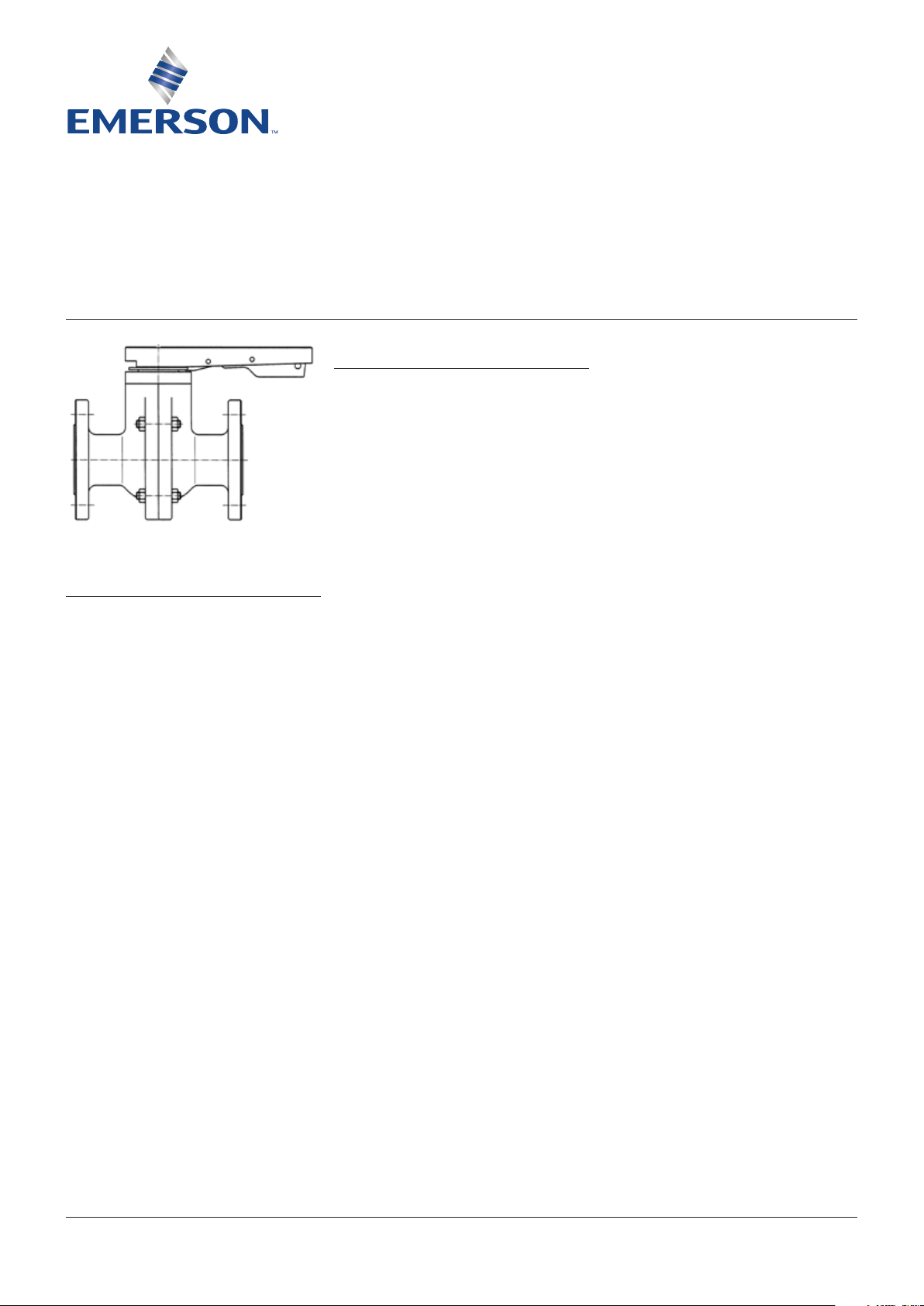
NEOTECHA NTB-NTC BALL VALVES
INSTALLATION AND MAINTENANCE INSTRUCTIONS
Before installation these instructions must be fully read and understood
2 SAFETY
Please also read through these notes carefully.
2.1 General potential danger due to:
a. Failure to observe the instructions
b. Improper use
c. Insufficiently qualified personnel
2.2 Correct use
2.2.1 Area of application
Ball valves are bubble-tight shut-off industrial
1 GENERAL INFORMATION ON THE
INSTALLATION AND MAINTENANCE
INSTRUCTIONS
These instructions contain information on
how the valve should be safely installed and
operated in the prescribed manner. If any
problems are encountered during installation
or operation which cannot be resolved with
the aid of the installation and maintenance
instructions, please contact the supplier or
manufacturer for more information.
These installation and maintenance
instructions comply with the applicable
ENsafety standards.
When installing the fitting, the operator or
the person responsible for the design of
the installation must ensure that applicable
national regulations are complied with.
The manufacturer reserves all rights to
maketechnical changes and improvements
atany time.
The use of these installation and maintenance
instructions assumes that the user is qualified
to “Qualified Personnel” level. Operating staff
must be given appropriate training in the
operating and maintenance instructions.
valves that can be used for the isolation,
throttling and regulation of corrosive gases,
liquids, pastes and powder products in
pipelines, vessels, apparatus etc.
The surfaces of the of the body parts, together
with the ball or C-core that are in contact
with the medium are coated with PFA. Ball
seats and control orifice plates are available
in various material types and can be used to
suitthe medium.
2.2.2 Performance data
Nominal diameter range:
DIN-PN 16 and JIS10K
DN15 / 20 / 25 / 40 / 50 / 65 / 80 / 100 / 150
(ANSI 6” face-to-face with extension)
ANSI 150lbs½”, ¾”, 1”, 1½”, 2”, 2½”
(DIN face-to-face), 3”, 4”, 6”
Pressure range:
16bar (0.1 mbar vacuum)
Test pressure = 1.5 x PN = 24bar
Temperature range:
-40°C to 180°C
Emerson.com/FinalControl © 2017 Emerson. All Rights Reserved. VCIOM-01973-EN 15/02
Page 2
NEOTECHA NTB-NTC BALL VALVES
INSTALLATION AND MAINTENANCE INSTRUCTIONS
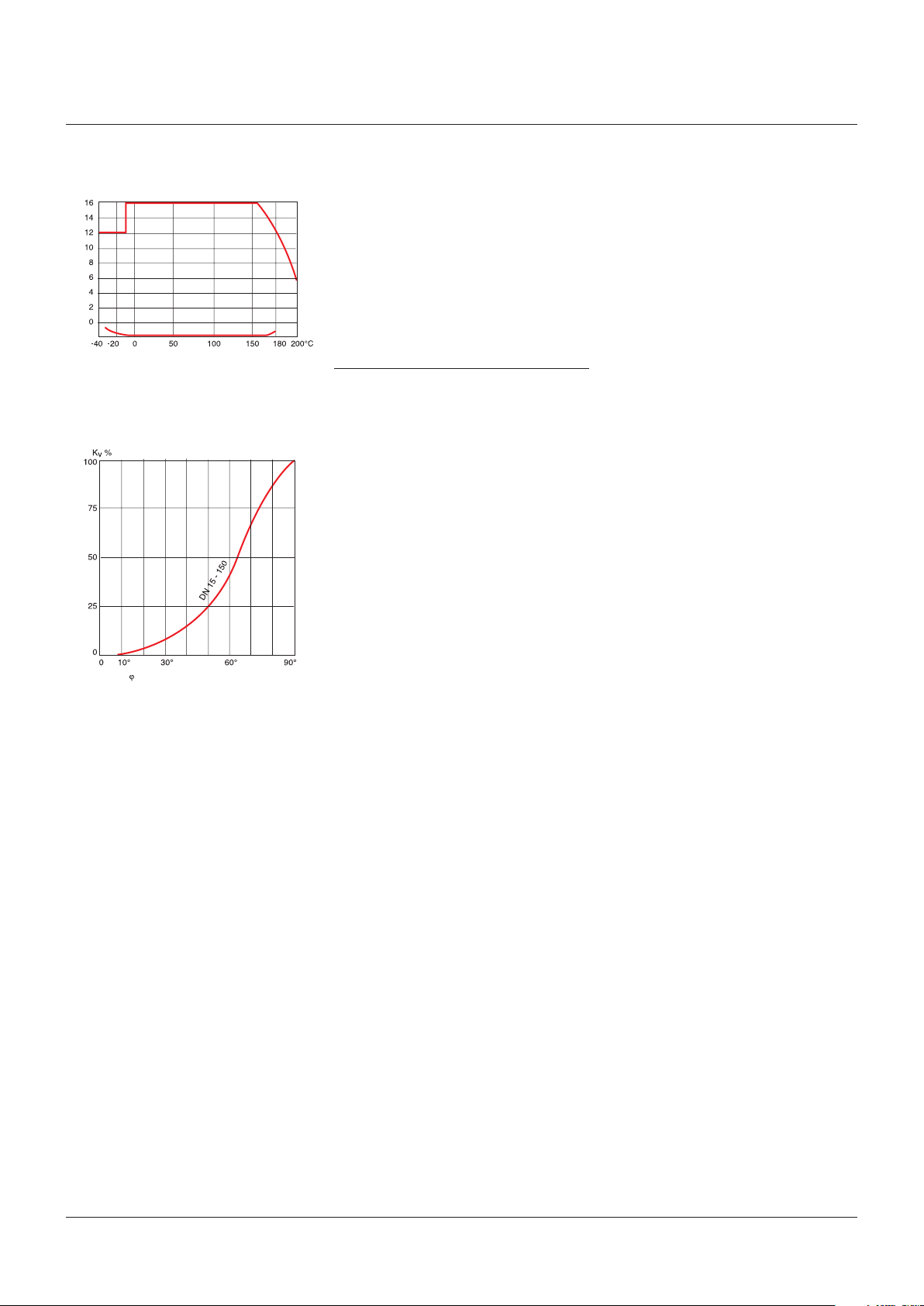
2.2.3 Pressure-temperature diagram for
NTB-NTC ball valves
bar
Vacuum
0.1 mbar
2.2.4 Flow characteristic for NTC control valves
(without control orifice plate)
Angular
position
2.2.5 Usage restrictions
Before the valve is installed, a check should be
made on the extent to which the coating of the
surfaces is resistant to the intended medium.
The same applies to stainless steel valves with
no additional coating. Refer to appropriate
literature or consult the manufacturer or
distributor for advice on this.
2.2.6 Modification prohibition
Mechanical modifications to the valves or the
use of other manufacturer’s parts for repair
purposes are not permissible, as otherwise
safety is no longer guaranteed. Repair work
must only be carried out by the manufacturer’s
trained personnel. The manufacturer and
supplier will accept no liability in the event
ofmisuse.
2.2.7 Warning about foreseeable misuse
Valves and their accessories (e.g. operating
elements) must not be misused as
climbingaids.
2.2.8 Duty to comply with the instructions
foroperation, maintenance and servicing
These instructions form part of the delivery
package and must be easily accessible to the
user. They should be protected from soiling
andkept in a suitable place.
3 SOURCES OF DANGER
3.1 External chemical effects
The valve body is either made of stainless steel
or is coated with a 2-part polyester paint. The
coating can be attacked externally by strong
solvents, leading to corrosion of the body.
If damage of this nature occurs, the effects
on the environment should be investigated
and the damage to the coating made good
in accordance with the manufacturer’s data.
Stainless steel valve bodies are not suitable
foruse with chlorine gas.
3.2 Mechanical
When using hand levers and handwheels,
it should be ensured that there is sufficient
clearance everywhere for the operator’s
hands,so that there is no risk of trapping.
3.3 Electrical
If static charges can lead to explosions,
the valve must be earthed by means of
the appropriate earthing accessory. As an
alternative, valves with electrically conductive
linings are available. For more information,
please contact the supplier or manufacturer.
3.4 Thermal
The operating temperature of the valve can
be up to a maximum of 200°C. Suitable
precautions should be taken to protect against
burns due to high or freezing temperatures.
In particular, insulated gloves should be worn
when using the hand lever, for example. In case
of fire, the mechanical strength of the PTFE
seals is no longer guaranteed above 200°C.
2
Page 3
NEOTECHA NTB-NTC BALL VALVES
INSTALLATION AND MAINTENANCE INSTRUCTIONS
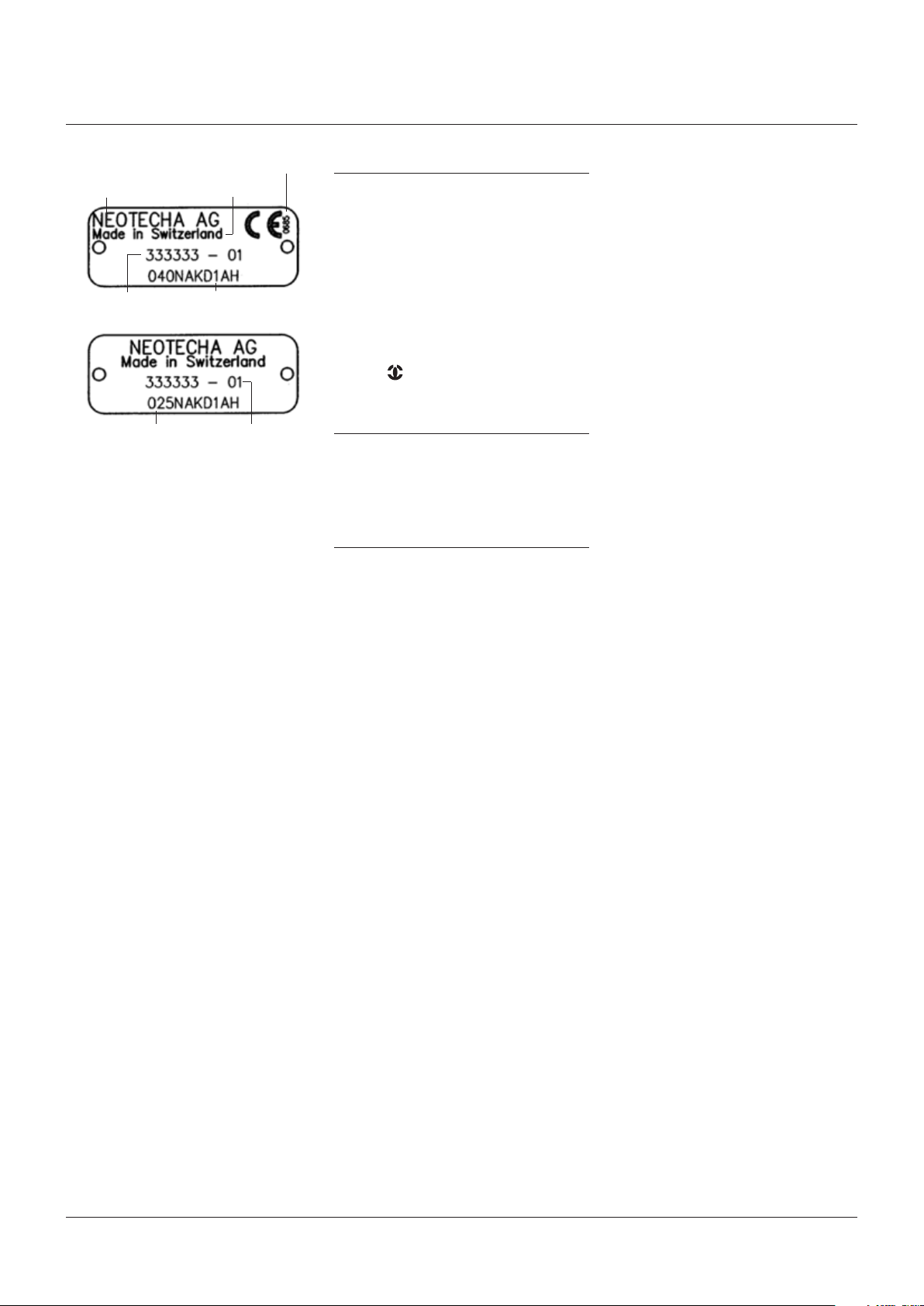
Number of the
notified body
Manufacturer Origin
Serial number Manufacturer’s code
Ball valve type
3.5 Requirements for the operator
This means people who are familiar with the
erection, installation, commissioning, operation
and maintenance of the product and have
appropriate qualifications relating to their
activities and functions, such as e.g.:
- Instruction in and duty to comply with all
installation-related, regional and internal
works regulations and requirements.
- Training or instruction in accordance with the
Safety Standards for personal care and use of
appropriate safety equipment and protective
workgear, like e.g. personal protection
equipment (insulated gloves or similar),
suitable for the operating conditions.
Furthermore, these people must have read
andunderstood these instructions.
3.6 Transport/storage
The valve is delivered with protective covers
which should protect against soiling and
mechanical effects. For this reason, the
protective covers should only be removed
immediately prior to installation.
The ball valve is shipped in the closed position.
3.7 Transport and storage conditions
- Transport and storage temperature
-20°C to +65°C.
- Protect against external force(impact,
shock,vibration).
- Do not damage the coating.
- In damp storage areas, a drying agent
or heating is required to protect against
condensation.
- Store the ball valve in a slightly open position.
3.8 Handling prior to installation
- On versions with protective covers,
only remove these immediately prior
toinstallation!
- Protect against the effects of weather,
e.g.dampness (or else use a drying agent).
- Proper treatment prevents damage.
Year of manufacture
4 IDENTIFICATION
Each ball valve is fitted with a rating plate giving
information on valve type and origin. When
ordering spare parts this information should
becarefully noted down each time.
Ball valves in the size range DN 15 to DN 25
have a standard rating plate with no CE mark.
Ball valves in the size range DN 40 to DN 150
are provided with a rating plate with a CE mark.
Additional identification on the valve in
accordance with DIN19, such as: DN, PN,
manufacturer’s logos of the Neotecha AG
company . The identification of the valve
body material is cast onto the valve.
5 DIMENSIONS AND WEIGHTS
Please refer to the product documentation
for any dimensions that are not contained in
the installation and maintenance instructions
andfor ball valve weights.
6 INSTALLATION
6.1 Installation in the pipeline
Fit the ball valve in the pipeline, ensuring that
the sealing surfaces on the faces of the flanges
are not damaged. The NTB ball valve can be
installed independently of the direction of
flow. On the other hand, the NTC can only be
installed in one direction, i.e. the arrow on the
side of the valve must point in the direction of
flow. Adequate clearance should be ensured
around the ball valve, so that it can be operated
and maintained easily.
The mounting flanges of the pipeline in which
the valve is to be installed must be aligned
axially and laterally, in order to prevent the
valve body being subjected to additional
stresses. Fit suitable flange packings, provided
that they are called for: then the fixing bolts
are inserted. Tightening the bolts in stages is
essential for an equal distribution of the of the
initial stress force of the clamping bolts.
The specified tightening torques must not
beexceeded.
The flanges must meet the following
requirements: cleaned and undamaged
matingsurface.
Flange packings are not required with flanges
with flat sealing surfaces. Additional packings
may possibly be required with rubberized
flanges.
3
Page 4

NEOTECHA NTB-NTC BALL VALVES
INSTALLATION AND MAINTENANCE INSTRUCTIONS
6.2 Dimensions of the mounting flanges for NTB-NTC ball and C valves DIN-PN 16
DIMENSIONS
DN D Tk n x d
mm inches mm mm mm
15 ½” 95 65 4 x 14
20 ¾” 105 75 4 x 14
25 1” 115 85 4 x 14
40 1½” 150 110 4 x 18
50 2” 165 125 4 x 18
65 2½” 185 145 4 x 18
80 3” 200 160 8 x 18
100 4” 220 180 8 x 18
150* 6” 279 241 8 x 22
* DN150 ball valve only as ANSI 6” version available
6.3 Dimensions of the mounting flanges for NTB-NTC valves ANSI B 16.10class150 (lbs)
DIMENSIONS
DN D Tk n x d
mm inches mm mm mm
15 ½” 89 60.3 4 x 16
20 ¾” 98 70.0 4 x 16
25 1” 108 79.5 4 x 16
40 1½” 127 98.5 4 x 16
50 2” 152 120.5 4 x 19
65 2½” 185 145.0 4 x 19
80 3” 190 152.5 4 x 19
100 4” 229 190.5 8 x 19
- 6” 279 241.0 8 x 22
6.4 Dimensions of the mounting flanges for NTB-NTC ball and C valves JIS-10K
6.5 Installation options
Ball valves can be equipped with various means
of operation e.g. with hand lever, handwheel,
electrical, pneumatic or hydraulic drive, or with
a drive linked to a position controller for NTC
control valves. The hand levers are supplied
complete with a notched plate which allows the
lever to be latched either in the end positions
only (version ZE) or in the end positions and
additionally in various intermediate positions
(version Z). In addition, the hand lever can be
provided with limit switches which indicate
“open” or “closed”.
For installation in exposed places, shaft
extensions in various lengths are available
forall sizes.
6.6 Bolted joints in the pipeline
All flange bolts must be used, even on
low-pressure systems. The specified tightening
toques for the bolts must always be adhered to.
6.7 Body variants
NTB and NTC ball valves have the same body
dimensions. The face-to-face and mounting
flange dimensions of the ball valve bodies
varyaccording to the various standards.
When used as an end of the line valve, it must
be secured in such a way that access to the
isolating valve is restricted when in service.
It should also be noted that when a valve is
used as the end valve of a pressurized system,
a dummy flange must be assembled.
DIMENSIONS
DN D Tk n x d
mm inches mm mm mm
15 ½” 95 70 4 x 15
20 ¾” 100 75 4 x 15
25 1” 125 90 4 x 19
40 1½” 140 105 4 x 19
50 2” 155 120 4 x 19
65 2½” 175 140 4 x 19
80 3” 185 150 8 x 19
100 4” 210 175 8 x 19
- 6” 279 241 8 x 22
* Ball valves DN150 only as ANSI 6” version available
4
Page 5

NEOTECHA NTB-NTC BALL VALVES
INSTALLATION AND MAINTENANCE INSTRUCTIONS
6.7.1 Face-to-face body dimensions for NTB-NTC ball valves
FACE-TO-FACE BODY DIMENSIONS
DN DIN-PN 16 ANSI-150lbs JIS-10K
mm inches mm mm mm
15 ½” 130 108 130
20 ¾” 150 117 150
25 1” 160 127 160
40 1½” 200 165 200
50 2” 230 178 230
65 2½” 290 290 (DIN dimension) 290
80 3” 310 203 310
100 4” 350 229 350
150 6” 480
ANSI-dim. 229
withextension
6.8 Step-by-step valve installation
1. Check that the distance between flanges matches the face-to-face dimension of the ball valve.
Before installing the valve, spread the mounting flanges apart sufficiently using a suitable tool.
2. Remove the protective caps and position the ball valve in the pipeline. When installing a
Cvalve, check that the arrow points in the direction of flow.
3. Insert the fixing bolts.
4. Tighten the flange bolts hand-tight as the tool holding the flanges apart is gradually removed.
Make sure that the flanges remaincorrectly aligned.
5. Tighten all flange bolts in opposite pair sequence. Refer to following table for tightening
torques.
267 480
ANSI-dim. 229
withextension
6.9 Recommended tightening torques for mounting flange bolts
6.9.1 Recommended tightening torques for NTB-NTC ball valves DIN-PN 16 and JIS-10K
RECOMMENDED TORQUES
DN
mm inches Nm
15 ½” 4 x M12 A2-70 10
20 ¾” 4 x M12 A2-70 15
25 1” 4 x M12 A2-70 20
40 1½” 4 x M16 A2-70 27
50 2” 4 x M16 A2-70 45
65 - 4 x M16 A2-70 60
80 3” 8 x M16 A2-70 60
100 4” 8 x M16 A2-70 45
- 6” 8 x M20 A2-70 85
Bolts
metric Class
Torque
6.9.2 Recommended tightening torques for NTB-NTC ball valves ANSI B 16.10class150 (lbs)
RECOMMENDED TORQUES
DN
mm inches
15 ½” ½” B7 9
20 ¾” ½” B7 13
25 1” ½” B7 18
40 1½” ½” B7 21
50 2” ⅝” B7 41
65 - ⅝” B7 52
80 3” ⅝” B7 52
100 4” ⅝” B7 38
- 6” ¾” B7 68
Bolts
UNC lbf·ft
Class
Torque
5
Page 6

NEOTECHA NTB-NTC BALL VALVES
INSTALLATION AND MAINTENANCE INSTRUCTIONS
6.10 Final checks
- Checking the ball position as far as the
fullyopen position.
- Cleaning and flushing the pipeline before
thefirst closure.
- Repeated opening and closing of the ball
valve, to ensure unrestricted movement
ofball and control shaft.
7 NOTES ON DANGERS DURING
INSTALLATION, OPERATION
ANDMAINTENANCE
Safe operation of the valve is only guaranteed
ifit has been correctly installed, commissioned
and maintained by qualified personnel
(see“Qualified Personnel”), taking into account
the warning information of these installation
and maintenance instructions.
In addition, compliance with the general
installation and safety regulations for the
pipeline or plant construction, together
with the correct use of tools and protective
equipment, must be ensured. The installation
and maintenance instructions must be
strictly followed when any work is carried
out on the valve or when handling the valve.
Non-observance can result in injuries or
damage to property. When the valve is used
as a final termination, a safety measure e.g.
a blank or dummy flange is recommended
when carrying out maintenance work. When
the valve is installed as an end of line valve,
theinformation given in DIN EN294 point 5
must be observed.
9 USE
9.1 Operation - general
NTB series ball valves should only be used
in the fully open or fully closed position, as
they are not designed for flow regulation.
Intermediate settings can result in turbulence,
leading to vibrations in the pipeline system
which then generates noise. If the flow has to
be regulated, an NTC series C valve should
be used. This type can also be fitted with
various control orifice plates. Refer to the flow
characteristic diagram for NTC control valves.
Operating:
Clockwise to close.
Counter clockwise to open.
9.2 Operation with hand lever
Neotecha ball valves and C valves are
supplied with a hand lever as standard, unless
anything different has been provided (except
DN150-6” -too high a torque). The hand lever
should always be fitted on the ball valve and
only removed when necessary for maintenance
purposes. When the hand lever points in the
direction of the pipeline, the ball valve is fully
open; when the hand lever is at right angles
to the pipeline, the valve is fully closed. The
hand lever should be turned clockwise to
closethevalve.
Nominal diameters 15 to 100 (½” to 4”)
Hand lever with notched plate with 10°
divisions, range 90°
Operating element: detent lever
8 COMMISSIONING
8.1 General commissioning
Before commissioning, the information relating
to material, pressure and temperature should
be compared with the installation diagram of
the pipeline system.
Tools for increasing the lever or handwheel
torque are not allowed.
Any debris left in the pipeline and valves
(dirt,welding beads, etc.) will inevitably
leadtoleakage.
Before each commissioning of a new system or
re-commissioning of a system after repair or
modification, it must be ensured that:
- All installation and assembly work has
been completed in accordance with the
regulations.
- Commissioning is only undertaken by
“Qualified Personnel”.
- The valve is in the correct operating position.
- New protective equipment is installed or
existing protective equipment repaired.
The hand lever and detent lever must not be
modified. The locking function is otherwise
adversely affected. Damaged hand levers
shouldbe exchanged.
9.3 Operation with drive
Thanks to its modular method of construction,
the NTB-NTC ball valve can be converted to
anautomatic drive at any time. In this case
it may be necessary to remove the ball valve
fromthe pipeline.
When drives or gear units are used, the
instructions of the particular manufacturer
areapplicable.
6
Page 7

NEOTECHA NTB-NTC BALL VALVES
INSTALLATION AND MAINTENANCE INSTRUCTIONS
10 SERVICING AND MAINTENANCE
No routine maintenance or lubrication is
required. However, for systems with high
temperatures, an inspection for leakage at
the flanges should be carried out shortly after
installation. The large difference between
the temperature related expansions of PTFE
and some metals can result in cold flow.
Tightening the bolts once again will eliminate
this problem. This process may possibly have to
be repeated several times. We recommend that
the valve is operated at least once a month.
11 CAUSE AND REMEDY OF OPERATING
FAULTS
If the valve function or operating action is
faulty, a check should be made to ensure that
the assembly and installation work has been
carried out and completed in accordance with
the installation and maintenance instructions.
The information relating to material, pressure,
temperature and direction of flow should be
compared with the installation diagram of the
pipeline system. Furthermore, a check should
be made on whether the installation conditions
correspond to the technical data given in the
data sheet or on the rating plate.
The safety regulations must always
beobservedwhen troubleshooting.
Repair work must only be carried out by
themanufacturer’s trained personnel.
ATTENTION!
Check that the pipe is depressurized and drained.
With corrosive, inflammable, aggressive or toxic
media, ventilate the pipeline system.
- Only allow assembly work to be carried out
byqualified personnel.
- Almost fully close the valve (note position
ofthe flat sections of the control shaft).
- Loosen all flange bolts and withdraw
themuntil the valve can be removed.
- Spread the flanges apart using a suitable
tooland withdraw the valve.
13 SPARE PARTS
Always provide the information in accordance
with the rating plate fitted on the mounting
flange when ordering seals and other
spareparts.
14 DISPOSAL
Hand in the correctly cleaned valve to the
scrapmaterial recycling plant.
Badly cleaned valves can cause severe burning
ofthe hands and other parts of the body.
If the valve is passed on to a third party, the
manufacturer no longer guarantees the valve.
12 DECOMMISSIONING
Removal of the valve for repair or servicing is
often carried out carelessly, as the valve has to
be repaired or replaced in any case. However, it
is recommended that the valve is removed with
care, without damaging the PTFE, so that the
possible cause of damage can be determined
after removal.
7
Page 8

Neither Emerson, Emerson Automation Solutions, nor any of their affiliated entities assumes responsibility for the selection, use or maintenance of any product.
Responsibility for proper selection, use, and maintenance of any product remains solely with the purchaser and end user.
Neotecha is a mark owned by one of the companies in the Emerson Automation Solutions business unit of Emerson Electric Co. Emerson Automation Solutions, Emerson
and the Emerson logo are trademarks and service marks of Emerson Electric Co. All other marks are the property of their respective owners.
The contents of this publication are presented for informational purposes only, and while every effort has been made to ensure their accuracy, they are not to be
construed as warranties or guarantees, express or implied, regarding the products or services described herein or their use or applicability. All sales are governed by
our terms and conditions, which are available upon request. We reserve the right to modify or improve the designs or specifications of such products at any time without
notice.
Emerson.com/FinalControl
 Loading...