

Page 1
Reference Manual
IP2013, Rev BA
February 2012
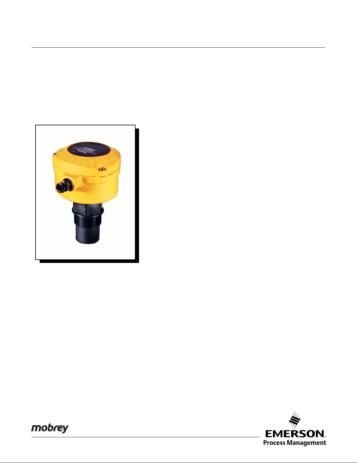
Mobrey MSP422
Ultrasonic Liquid Level Transmitter
Mobrey MSP422
www.mobrey.com
Page 2

Page 3
Reference Manual
NOTICE
Rev BA , Rev BA
February 2012
Mobrey MSP422
Mobrey MSP422 Ultrasonic
Liquid Level Transmitter
Read this manual before working with the product. For personal and system safety, and for
optimum product performance, make sure you thoroughly understand the contents before
installing, using, or maintaining this product.
The products described in this document are NOT designed for nuclear-qualified
applications.
This device complies with part 15 of the FCC rules. Operation is subject to the following two
conditions: (1) This device may not cause harmful interference, and (2) this device must
accept any interference received, including interference that may cause undesired
operation.
www.mobrey.com
Page 4

Page 5

Reference Manual
Rev BA , Rev BA
February 2012
Mobrey MSP422
Table of Contents
SECTION 1
Introduction
SECTION 2
Transmitter Overview
SECTION 3
Installation
Safety Messages. . . . . . . . . . . . . . . . . . . . . . . . . . . . . . . . . . . . . . . . . 1-1
Manual Overview. . . . . . . . . . . . . . . . . . . . . . . . . . . . . . . . . . . . . . . . . 1-2
Customer Support . . . . . . . . . . . . . . . . . . . . . . . . . . . . . . . . . . . . . . . . 1-2
Product Recycling/Disposal. . . . . . . . . . . . . . . . . . . . . . . . . . . . . . . . . 1-2
Theory of Operation. . . . . . . . . . . . . . . . . . . . . . . . . . . . . . . . . . . . . . . 2-1
Components of the Transmitter . . . . . . . . . . . . . . . . . . . . . . . . . . . . . . 2-2
Safety Messages. . . . . . . . . . . . . . . . . . . . . . . . . . . . . . . . . . . . . . . . . 3-1
Before You Install . . . . . . . . . . . . . . . . . . . . . . . . . . . . . . . . . . . . . . . . 3-2
General Considerations . . . . . . . . . . . . . . . . . . . . . . . . . . . . . . . . . 3-2
Mechanical Installation . . . . . . . . . . . . . . . . . . . . . . . . . . . . . . . . . . . . 3-3
Mounting Considerations . . . . . . . . . . . . . . . . . . . . . . . . . . . . . . . . 3-3
Liquid Surface Conditions. . . . . . . . . . . . . . . . . . . . . . . . . . . . . . . . 3-4
In-tank Effects. . . . . . . . . . . . . . . . . . . . . . . . . . . . . . . . . . . . . . . . . 3-4
Mounting the Transmitter Above the Liquid Surface . . . . . . . . . . . 3-5
Electrical Installation . . . . . . . . . . . . . . . . . . . . . . . . . . . . . . . . . . . . . . 3-7
Cabling the Transmitter . . . . . . . . . . . . . . . . . . . . . . . . . . . . . . . . . 3-7
After Completing the Wiring . . . . . . . . . . . . . . . . . . . . . . . . . . . . . . 3-7
Lightning / Surge Protection and Other Loop Devices . . . . . . . . . . 3-8
SECTION 4
Starting up
Safety Messages. . . . . . . . . . . . . . . . . . . . . . . . . . . . . . . . . . . . . . . . . 4-1
Overview . . . . . . . . . . . . . . . . . . . . . . . . . . . . . . . . . . . . . . . . . . . . . . . 4-2
Power Up . . . . . . . . . . . . . . . . . . . . . . . . . . . . . . . . . . . . . . . . . . . . 4-2
Before Programming . . . . . . . . . . . . . . . . . . . . . . . . . . . . . . . . . . . 4-2
MSP422 Menu Map . . . . . . . . . . . . . . . . . . . . . . . . . . . . . . . . . . . . 4-3
Programming The MSP422. . . . . . . . . . . . . . . . . . . . . . . . . . . . . . . . . 4-4
Display Units. . . . . . . . . . . . . . . . . . . . . . . . . . . . . . . . . . . . . . . . . . 4-4
First Measurements . . . . . . . . . . . . . . . . . . . . . . . . . . . . . . . . . . . . 4-5
Setting the Bottom Reference . . . . . . . . . . . . . . . . . . . . . . . . . . . . 4-6
Setting 4 mA and 20 mA Levels . . . . . . . . . . . . . . . . . . . . . . . . . . . 4-6
Setting the Output Damping. . . . . . . . . . . . . . . . . . . . . . . . . . . . . . 4-7
Selecting the Action on Alarm Condition . . . . . . . . . . . . . . . . . . . . 4-8
Setting 4 mA and 20 mA Levels Using Ranging. . . . . . . . . . . . . . . 4-9
Learn About Echoes From False Targets. . . . . . . . . . . . . . . . . . . 4-10
Final Checks . . . . . . . . . . . . . . . . . . . . . . . . . . . . . . . . . . . . . . . . . . . 4-11
Power Failure. . . . . . . . . . . . . . . . . . . . . . . . . . . . . . . . . . . . . . . . . . . 4-11
www.mobrey.com
Page 6

Mobrey MSP422
Reference Manual
IP2013, Rev BA
February 2012
SECTION 5
Service and
Troubleshooting
APPENDIX A
Reference Data
APPENDIX B
Product Certifications
Safety Messages. . . . . . . . . . . . . . . . . . . . . . . . . . . . . . . . . . . . . . . . . 5-1
Servicing . . . . . . . . . . . . . . . . . . . . . . . . . . . . . . . . . . . . . . . . . . . . . . . 5-2
Diagnostics for The MSP422. . . . . . . . . . . . . . . . . . . . . . . . . . . . . . . . 5-2
General Troubleshooting . . . . . . . . . . . . . . . . . . . . . . . . . . . . . . . . 5-2
Error Messages . . . . . . . . . . . . . . . . . . . . . . . . . . . . . . . . . . . . . . . 5-2
Specifications. . . . . . . . . . . . . . . . . . . . . . . . . . . . . . . . . . . . . . . . . . . .A-1
Temperature and Pressure Ratings. . . . . . . . . . . . . . . . . . . . . . . . . . .A-2
Load Limitations. . . . . . . . . . . . . . . . . . . . . . . . . . . . . . . . . . . . . . . . . .A-2
Dimension Drawings . . . . . . . . . . . . . . . . . . . . . . . . . . . . . . . . . . . . . .A-3
Safety Messages. . . . . . . . . . . . . . . . . . . . . . . . . . . . . . . . . . . . . . . . .B-1
Manufacturing Location . . . . . . . . . . . . . . . . . . . . . . . . . . . . . . . . . . . .B-2
European Union Directive Information. . . . . . . . . . . . . . . . . . . . . . . . .B-2
Non-hazardous Location Certifications . . . . . . . . . . . . . . . . . . . . . . . .B-2
American and Canadian Certifications. . . . . . . . . . . . . . . . . . . . . .B-2
TOC--2
Page 7

Reference Manual
IP2013, Rev BA
February 2012
Mobrey MSP422
Section 1 Introduction
Safety Messages . . . . . . . . . . . . . . . . . . . . . . . . . . . . . . . . . page 1-1
Manual Overview . . . . . . . . . . . . . . . . . . . . . . . . . . . . . . . . page 1-2
Customer Support . . . . . . . . . . . . . . . . . . . . . . . . . . . . . . . page 1-2
SAFETY MESSAGES Procedures and instructions in this manual may require special precautions to
ensure the safety of the personnel performing the operations. Infor mation that
raises potential safety issues is indicated by a warning symbol ( ). Refer to
the safety messages listed at the beginning of each section before performing
an operation preceded by this symbol.
Failure to follow these installation guidelines could result in death or serious
injury.
• Make sure only qualified personnel perform the installation.
• Use the equipment only as specified in this manual. Failure to do so may
impair the protection provided by the equipment.
Explosions could result in death or serious injury.
• The Mobrey MSP422 is only for use in a non-hazardous location
Electrical shock could cause death or serious injury.
• Use extreme caution when making contact with the leads and terminals.
Any substitution of non-recognized parts may jeopardize safety. Rep air, e.g. substitution
of components etc., may also jeopardize safety and is under no circumstances allowed.
www.mobrey.com
Page 8

Reference Manual
IP2013, Rev BA
Mobrey MSP422
February 2012
MANUAL OVERVIEW This manual provides installation, configur ation, and maintenance info rmation
for the Mobrey MSP422 ultrasonic level transmitter.
Section 2: Transmitter Overview
Section 3: Installation
Section 4: Starting up
Section 5: Service and Troubleshooting
Appendix A: Reference Data
Appendix B: Product Certifications
CUSTOMER SUPPORT For the latest customer support information, visit www.mobrey.com, and then
click on the quick links Mobrey Service or Product Support.
Individuals who handle products exposed to a hazardous substance can avoid injury if they
are informed of, and understand, the hazard. If the product being returned was exposed to a
hazardous substance as defined by OSHA, a copy of the required Material Safety Data
Sheet (MSDS) for each hazardous substance identified must be included with the returned
goods.
PRODUCT
RECYCLING/DISPOSAL
Recycling of equipment and packaging should be taken into consideration.
The product and packaging should be disposed of in accordance with local
and national legislation.
1-2
Page 9
Reference Manual
Distance
Level
Bottom Reference
IP2013, Rev BA
February 2012
Mobrey MSP422
Section 2 Transmitter Overview
Theory of Operation . . . . . . . . . . . . . . . . . . . . . . . . . . . . . .page 2-1
Components of the Transmitter . . . . . . . . . . . . . . . . . . . . page 2-2
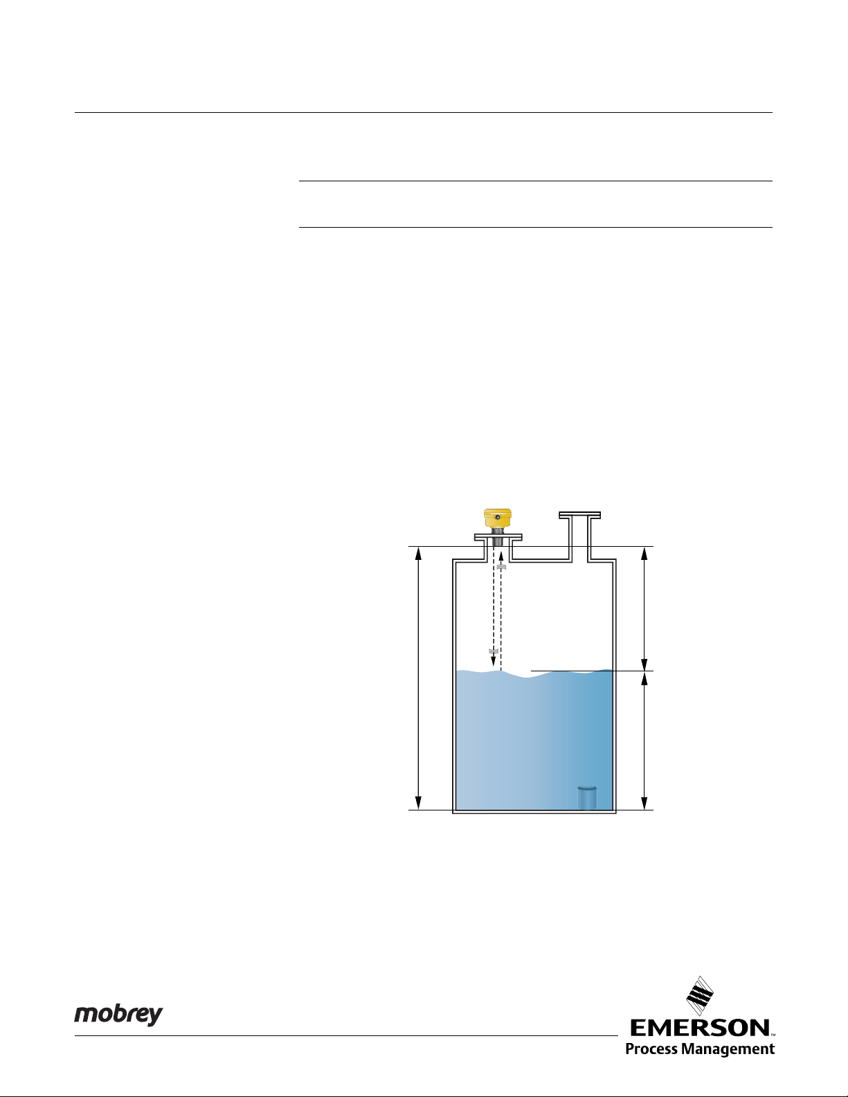
THEORY OF OPERATION The Mobrey MSP422 ultrasonic level transmitter is designed to be mounted
above a liquid and uses ultrasonic pulses to continuously measure the
distance to the liquid surface. The microprocessor-controlled electronics
measures the time delay between the transmitting and the receiving of the
reflected signals to calculate the distance (Figure 2-1).
When programmed with the bottom reference of the application – usually the
bottom of a tank – the MSP422 computes the liquid depth (level) and outputs
a 4–20 mA signal proportional to that level.
An LCD screen inside the enclosure displays the selected measurement.
Programming of the MSP422 is achieved using the integral push-buttons
inside the enclosure and the menu system shown on the LCD screen.
Figure 2-1. Typical Applica tio n
Using a Mobrey MSP422
Transmitter
The MSP422 may be mounted in a non-hazardous areas only.
www.mobrey.com
Page 10
Mobrey MSP422
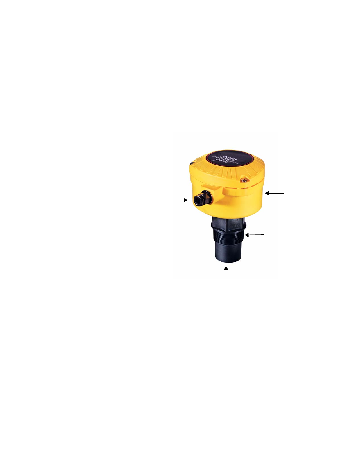
M20
Conduit
Thread
Transmitter Face
2-in. Mounting
Thread
Electronics
Housing
MSP422 FEATURES
Supplied With:
1 x Cable Gland and Dust Cap
Reference Manual
IP2013, Rev BA
February 2012
COMPONENTS OF THE
TRANSMITTER
Figure 2-2. The Mobrey MSP
Series Transmitters
The Mobrey MSP422 has a housing containing advanced electronics for
signal processing, and terminals for connecting the external power supply.
The electronics produces an ultrasonic signal from the transmitter face.
It is a two-wire, loop-powered transmitter; the two wires are used for both
24 Vdc power supply connections and the 4–20 mA an alo g outpu t si gn a l.
A two-core, shielded/screened cable is required (not supplied).
A comprehensive specification for the Mobrey MSP422 is in the section
“Specifications” on page A-1.
2-2
Page 11
Reference Manual
IP2013, Rev BA
February 2012
Mobrey MSP422
Section 3 Installation
Safety Messages . . . . . . . . . . . . . . . . . . . . . . . . . . . . . . . . . page 3-1
Before Yo u Install . . . . . . . . . . . . . . . . . . . . . . . . . . . . . . . .page 3-2
Mechanical Installation . . . . . . . . . . . . . . . . . . . . . . . . . . .page 3-3
Electrical Installation . . . . . . . . . . . . . . . . . . . . . . . . . . . . . page 3-7
SAFETY MESSAGES Procedures and instructions in this section may require special precautions to
ensure the safety of the personnel performing the operations. Infor mation that
raises potential safety issues is indicated by a warning symbol ( ). Please
refer to the following safety messages before performing an operation
preceded by this symbol.
Explosions could result in death or serious injury:
• The Mobrey MSP422 is only for use in a non-hazardous location
Failure to follow safe installation and servicing guidelines could result in death or
serious injury:
Make sure only qualified personnel perform the installation.
Use the equipment only as specified in this manual. Failure to do so may impair the
protection provided by the equipment.
Do not perform any service other than those contained in this manual unless you are
qualified.
Process leaks could result in death or serious injury.
Make sure that the transmitter is handled carefully.
High voltage that may be present on leads could cause electrical shock:
Avoid contact with leads and terminals.
Make sure the main power to the Mobrey MSP422 transmitter is off and the lines to any
other external power source are disconnected or not powered while wiring.
www.mobrey.com
Page 12

Mobrey MSP422
BEFORE YOU INSTALL The MSP422 is used for level measurement.
The transmitter must be installed in a location where it is protected from
ultraviolet radiation to prevent long term degradation of the plastics used
e.g. shrouded from direct sunlight.
It is important to correctly position the transmitter for reliable ultrasonic level
measurement. For maximum accuracy and stability of the level measurement
reading, the transmitter should always be shrouded from direct sunlight and
radiated heat.
The transmitter may be site-tuned to deal with most application conditions, but
it is recommended that the following guidelines be adopted where relevant.
NOTE:
The Mobrey MSP422 is designed to be mounted in a non-metallic fitting or
flange. The use of metallic fittings/flanges is not recommended.
General Considerations Guidelines:
a) Installation must be carried out by suitably trained personnel in
accordance with the applicable code of practice.
Reference Manual
IP2013, Rev BA
February 2012
b) If the equipment is likely to come into contact with aggressive substances,
it is the responsibility of the user to take suitable precautions that prevent
it from being adversely affected, thus ensuring that the type of protection
is not compromised.
Aggressive Substances are acidic liquids or gases that may attack met als
or solvents that may affect polymeric materials.
Suitable Precautions are regular checks as part of routine inspections, or
establishing, from the material's datasheet, that it is resistant to specific
chemicals.
c) The equipment must only be cleaned with a damp cloth.
d) The equipment is not intended to be repaired by the user and is to be
replaced by an equivalent unit. Repairs should only be carried out by the
manufacturer or approved repairer.
e) The transmitter is Double Insulated, and therefore Protective Earthing is
not required.
f) To maintain protection against the possible spread of fire, the supply to
the equipment must be limited to 3.75 Amps by a fuse or other mean s
g) Note that if the equipment is used in a manner not specified by the
manufacturer, the protection afforded by the equipment may be impaired.
h) The transmitter complies with the European Directive for Electro Magnetic
Compatibility (EMC) Class B. To ensure electro-magnetic compatibility in
any member state, it should not be installed in a reside ntial area.
3-2
NOTE:
It is not advisable to mount the transmitter in close proximity to a source of
electrical noise such as a variable-speed drive, or other high-powered
electrical device.
Page 13

Reference Manual
IP2013, Rev BA
February 2012
MECHANICAL
INSTALLATION
Mobrey MSP422
Mounting
Considerations
Guidelines:
a) The transmitter should be mounted above the liquid surface using the
2-inch thread provided, but not closer than 12 in. (0,3 m) to the surface.
The transmitter does not detect any liquid surface closer than
12 in. (0,3 m) to the transmitter face. (See "Mounting the Transmitter
Above the Liquid Surface" on page 3-5).
Optional flanges and bracket kits are available to help mounting.
b) The transmitter should be mounted vertically to ensure a good echo from
the liquid surface. The beam half angle of the transmitter is 6 degrees.
(See Figure 3-1 on page 3-4).
c) Obstructions in the tank, or well, may generate echoes which can be
confused with the real liquid surface echo. Obstructions within the beam
angle generate strong false echoes. Wherever possible, the transmitter
should be positioned to avoid false echoes.
d) To avoid detecting unwanted objects in the tank or well , it is advisable to
maintain a distance of at least 1.3 in. from the ce nter line of the transmitter
for every foot (11 cm per meter) range to the obstruction.
e) No false echoes are generated if the transmitter is located near the side of
the tank or well, and the wall is smooth and free of protrusions. However,
there will still be a reduction in the echo size. It is recommended that the
transmitter be mounted no closer than 12 in . (0,3 m ) to the wall to avoid a
large reduction in the echo size.
f) If the transmitter is mounted in an enclosed tank with a domed top, avoid
mounting the transmitter in the center of the tank roof because this could
act as a parabolic reflector and create unwanted echoes.
g) Avoid applications where heavy condensation could fo rm on the
transmitter face.
h) If the transmitter is mounted in a stand-off or nozzle, the transmitter face
should protrude at least 0.2 in. (5 mm) into the tank. If this is not possible,
see "Mounting the Transmitter Above the Liquid Surface" on page 3-5).
i) If the transmitter is used in environments where direct sunlight can cause
high surface temperatures on exposed instruments, a sun-shade is
recommended.
3-3
Page 14

Mobrey MSP422
Max. 3°
C
Use Non-metallic
Fitting / Flange
C =1.3 in./ft. (11 cm/m)
C Min. = 12 in. (0,3 m)
6° Beam
Half Angle
Figure 3-1. Min And Max
Distances From Tank Wall
Reference Manual
IP2013, Rev BA
February 2012
Liquid Surface
Conditions
Guidelines:
a) Foaming liquids can reduce the size of the returned echo beca use foam is
a poor ultrasonic reflector. Mount an ultrasonic tran smitter ove r an area of
clear liquid, such as near the inlet to a tank or well. In extreme conditions,
or where this is not possible, the transmitter may be mounted in a vented
stilling tube provided that the inside measurement of the stilling tube is at
least 4 in. (100 mm) and is smooth and free from joints or protrusions. It is
important that the bottom of the stilling tube stays covered to prevent the
ingress of foams.
b) Avoid mounting the transmitter directly over any inlet stream.
In-tank Effects Guidelines:
a) Stirrers or agit ators can cause a vortex. Moun t the transmitter of f-center of
any vortex to maximize the return echo.
b) If stirrer blades become uncovered, they create echoes as they pass
through the ultrasonic beam. The transmitter can learn to ignore these
false echoes (see "Learn About Echoes From False Targets" on
page 4-10).
c) In tanks with rounded or conical bottoms, mount the transmitter off-center .
If needed, a perforated reflector plate can be installed on the tank bottom
directly under the transmitter center line to ensure a satisfactory return
echo.
d) Avoid detecting pump casings, as the liquid falls away, by not mounting
the transmitter directly above pumps. If this is not possible, fine-tuning of
the transmitter on-site may be required.
3-4
Page 15

Reference Manual
IP2013, Rev BA
February 2012
Mobrey MSP422
Mounting the Transmitter
Above the Liquid Surface
A 2-in. thread is provided to mount the transmitter. The thread form is either
2-in. BSPT or 2-in. NPT, and is clearly marked on the hexagon of the
transmitter body.
NOTE:
The Mobrey MSP422 is designed to be mounted in a non-metallic fitting or
flange. The use of metallic fittings/flanges is not recommended.
To help installation, flange accessories and bracket kits are available from
Mobrey.
Procedure:
1. Ensure that the transmitter is perpendicular to the liquid surface to
maximize the return echo size.
2. Check that the maximum liquid level will not enter the 12-in. (0,3 m)
blanking zone of the transmitter.
3. When installing in a tank with a nozzle or stand-off
(Figure 3-2 on page 3-6):
a) Use PTFE tape on the screw thread (Figure 3-2 on page 3-6).
b) Lower transmitter into the tank through the process connection.
c) Turn the transmitter until it is properly secured in the process
connection (Figure 3-2 on page 3-6).
d) Tighten to a torque of 1.5 lbf.ft (2 Nm) using the hexagon. Do not use
the transmitter housing to tighten.
NOTE:
If the transmitter face does not protrude into the vessel, note the dimensions
in Table 3-1 for Figure 3-2, and ensure that the nozzle/vessel weld is smooth
and free from internal weld beads or other projections.
4. When installing using a bracket kit (Figure 3-3 on page 3-6):
a) Attach bracket to the disc using the 3 screws provided.
b) Attach bracket and disc to a support. The combined weight of bracket
and disc is 16 oz (0,5 kg). For transmitter weight, see "Specifications"
on page A-1.
c) Use PTFE tape on the screw thread of the transmitter
(Figure 3-2 on page 3-6).
d) Insert the transmitter into the disc.
e) Tighten to a torque of 1.5 lbf.ft (2 Nm) using the hexagon. Do not use
the transmitter housing to tighten.
NOTE:
The bracket kit contains a stainless steel angle bracket and PVC threaded
disc, which may be used to mount the transmitter on a support over the liquid
surface. The bracket and disc dimensions are in Figure A-4 on page A-4.
3-5
Page 16

Mobrey MSP422
PTFE
L
D
Tighten To A To rqu e Of 1 .5 lb f.ft (2 Nm)
Using The Hexagon. Do Not Use The
Housing To Tighten
Use Non-metallic
Fitting / Flange
No. 4X 13 Long Self Tap
Screw (3 Positions)
Carbon Steel (Zinc Plated)
PVC Disc
Stainless Steel Bracket
Note: Combined weight of bracket
and disc is 16 oz (0,5 kg)
Figure 3-2.
Mounting The Mobrey MSP422
Using A Nozzle/Stand-off
Reference Manual
IP2013, Rev BA
February 2012
NOTE:
If the transmitter face does not protrude into the vessel, note the dimensions
in Table 3-1 for Figure 3-2, and always ensure that the nozzle/vessel weld is
smooth and free from internal weld beads or other projections.
Table 3-1. Nozzle Diameter
Size (D) and Max Length (L)
Figure 3-3.
Mounting the Mobrey MSP422
Using a Bracket Kit
Nozzle Diameter Size (D) Maximum Nozzle Length (L)
DN50 (2 in.) 4 in. (100 mm)
DN80 (3 in.) 6.3 in. (160 mm)
DN100 (4 in.) 6.3 in. (160 mm)
DN125 (5 in.) 11.8 in. (300 mm)
3-6
Page 17

Reference Manual
Min. 12 Vdc
0.15 to 0.31 in.
(Ø4 to 8 mm)
Twisted-pair, Screened
Min. 0.22 mm
2
(24 SWG / 23 AWG)
Max. 1.5 mm
2
(16 SWG / 18 AWG)
+12 to 30 Vdc
0 Vdc
Max. 3000 m (9750 ft.)
T1: 24 Vdc
T2: 0 Vdc
IP2013, Rev BA
February 2012
Mobrey MSP422
ELECTRICAL
INSTALLATION
NOTE!
The MSP422 is not intrinsically safe certified, and is therefore for use in
non-hazardous (Ordinary Location) installations only.
Cabling the Transmitter The Mobrey MSP422 is a two-wire, loop-powered transmitter requiring an
external 24 Vdc power supply. There is one M20x1.5 cable entry. A suitable
conduit system or cable gland must be used to keep the weather-proof rating.
To cable the transmitter:
1. Make sure that the power supply is switched off.
2. Remove the cover of the transmitter housing.
3. Pull the cable through the cable gland /conduit.
4. Wire the transmitter as shown in Figure 3-4.
5. Connect the cable screen (shield) to ground at one end only.
6. Replace the cover, tighten the cable gland.
Figure 3-4. MSP422 Wiring
After Completing the
Wiring
To maintain the weather-proof rating and hazardous area protection of the
transmitter, ensure all cable glands, blanking plugs, and seals are in good
condition.
Check that the cover seal is in good condition, and not twisted or misaligned
in the seal location groove. When replacing the cover, tighten the three cover
screws evenly to exert uniform pressure on the cover seal.
3-7
Page 18

Mobrey MSP422
Reference Manual
IP2013, Rev BA
February 2012
Lightning / Surge
Protection and Other
Loop Devices
If the area is prone to lightning strike s or vo ltage surges, a suppressor device
may be installed between the transmitter and the control unit.
If an additional loop-powered device or sepa rately powered device is included
in the two-wire loop, the transmitter must receive a minimum voltage of
12 Vdc at 21 mA loop current. (See "Load Limitations" on pag e A-2).
3-8
Page 19

Reference Manual
IP2013, Rev BA
February 2012
Mobrey MSP422
Section 4 Starting up
Safety Messages . . . . . . . . . . . . . . . . . . . . . . . . . . . . . . . . . page 4-1
Overview . . . . . . . . . . . . . . . . . . . . . . . . . . . . . . . . . . . . . . .page 4-2
Programming The MSP422 . . . . . . . . . . . . . . . . . . . . . . . . page 4-4
Final Checks . . . . . . . . . . . . . . . . . . . . . . . . . . . . . . . . . . . .page 4-11
Power Failure . . . . . . . . . . . . . . . . . . . . . . . . . . . . . . . . . . . page 4-11
SAFETY MESSAGES Procedures and instructions in this section may require special precautions to
ensure the safety of the personnel performing the operations. Infor mation that
raises potential safety issues is indicated by a warning symbol ( ). Refer to
the safety messages listed at the beginning of each section before performing
an operation preceded by this symbol.
Explosions could result in death or serious injury:
• The Mobrey MSP422 is only for use in a non-hazardous location
Failure to follow safe installation and servicing guidelines could result in death or
serious injury:
Make sure only qualified personnel perform the installation.
Use the equipment only as specified in this manual. Failure to do so may impair the
protection provided by the equipment.
Do not perform any service other than those contained in this manual unless you are
qualified.
www.mobrey.com
Page 20

Reference Manual
IP2013, Rev BA
Mobrey MSP422
February 2012
OVERVIEW The Mobrey MSP422 ultrasonic level transmitter is operated from a menu of
parameters, each held in a specific memory location within the transmitter.
The memory locations may be pictured as a matrix, and navigated for
programming the instrument using
The Integral Display Menu structure is shown in Figure 4-1 on pag e4-3.
The transmitter is pre-programmed at the factory with a value in each
parameter location so that when the power is first applied, the transmitter
gives a sensible reading.
This section details the local programming using the push-buttons provided
inside the transmitter.
and steps.
Power Up When the power is turned on, the transmitter takes several seconds to
initialize. The display will run a set-up routine, first illuminating all display
characters, and then showing the software revision number. Finally, a full set
of zeros is displayed while the microprocessor identifies the correct return
echo. After these checks are complete, the display indicates the live
measurement based upon the factory default values in memory.
On a new instrument aimed at a good targ et, the transmitter calcul ates a level
reading based upon the default value for the bottom reference.
The transmitter is now ready to be set-up with details of the application.
The transmitter may be programmed prior to, or after, installation. All
programmed data is retained in the transmitter memory after the power is
turned off.
Before Programming Important notes to help you program the transmitter:
a) Do not allow rain, or water , to enter the transmitter dur ing programming or
the circuit boards may be damaged.
b) See the instructions below on how to use the push-buttons to navigate
through the programming menu and select or enter application data.
c) Push the buttons firmly, but not too hard, to avoid damaging the circuit
boards. Also, to avoid entering incorrect data, do not push the buttons too
fast.
d) Holding down the green button
e) Pressing the red button
the previous level in the menu (see Figure 4-1 on page 4-3).
Note, however , if the red button
has been made or new data has been entered (i.e. stop ped flashi ng), this
option selection / new data will automatically be saved (see Figure 4-1).
at certain locations in the menu returns you to
scrolls through any option list.
is pressed after a menu option selection
4-2
Page 21

Reference Manual
IP2013, Rev BA
February 2012
MSP422 Menu Map
Figure 4-1. MSP422 Menu Map
Mobrey MSP422
4-3
Page 22

Mobrey MSP422
Reference Manual
IP2013, Rev BA
February 2012
PROGRAMMING
THE MSP422
Refer the Integral Display menu on a card tucked between the housing and
body, and in Figure 4-1 on page 4-3.
Display Units The display units are indicated by the position of the decimal point in the
displayed PV value:
Units Display
m 8.000
ft. 26.24
in. 314.9
Default values are as follows:
MSP422-B28: m
MSP422-N28: ft.
NOTE:
See Figure 4-1 on page 4-3 for a map of the programming menu structure
showing how to access all the menu options and return to the PV display.
To change the display units:
a) Start from the PV display (see the note above.)
b) Hold down the blue button
c) The display units will then change according to the following sequence:
MSP422-B28: Metres to Feet, Feet to Inches, and Inches to Metres.
MSP422-N28: Feet to Inches, Inches to Metres, and Metres to Feet.
d) Continue to hold down the blue button
unit in the above sequence after every three seconds.
e) Confirm the display units by releasing the blue button
The same units must be used when programming in the bottom reference and
the 4 and 20 mA points.
for 10 seconds, but do not release it yet.
to change to the next display
.
4-4
The 4–20 mA output may be set to operate over all or just a part of the total
measuring range. There is no limit on the minimum span o f the current output,
although a span below 4 in. (100 mm) is not recommended.
The 4 mA level may be set above or below the 20 mA level to suit the
monitoring or control equipment.
NOTE:
The MSP422 measures and calculates in metres. The display units are
derived as a last operation using a pre-programmed conversion factor.
Page 23

Reference Manual
Distance-to-target
Depth (Level)
Bottom Reference
IP2013, Rev BA
February 2012
Mobrey MSP422
First Measurements With the transmitter installed and display units selected, the display will show
what the instrument calculates as the liquid depth (level). This value is
calculated by the microprocessor as being the difference between the
distance-to-target being measured and the default value for the datum or
bottom reference (b.rEF).
Figure 4-2. Bottom Reference
Before changing any of the default values, press the blue button
to change
the PV display to indicate distance-to-target, as measured by the transmitter
from the transmitter face. This value is shown alternately with the text “diSt”
to indicate the display is in distance mode. The calculation can be checked
against a manual measurement if required.
NOTE:
A useful feature at this stage is that the transmitter can be used as an
electronic tape measure. With an empty tank or vessel, the transmitter will
read the distance to the bottom of the tank. This distance can be noted and
later used when setting b.rEF.
Press the blue button
again to get to the echo size. This is a scale of 0 to
100. (It is possible to record a value greater than 100). With the display in this
mode, the central “:” cursor will flash once for every echo received, which
under normal circumstances will be once per second.
NOTE:
It is useful at this point to check that the maximum echo size available is be ing
received. Adjust the position of the instrument until the highest echo size is
continually shown. In most applications, the signal strength will vary over a
wide range: 20 to 80.
Press the blue button
again to return to the original level reading and start
the calibration routine.
NOTE:
The output of the transmitter will vary during programming, as the various
default values are changed. The display will automatically revert to the level
or distance reading from any other display after a period of four minutes.
4-5
Page 24

Mobrey MSP422
Reference Manual
IP2013, Rev BA
February 2012
Setting the Bottom
Reference
Screen display: b.rEF
Defaults: 8.000 (m), 26.24 (ft.), 314.9 (in.)
NOTE:
See Figure 4-1 on page 4-3 for a map of the programming menu structure and
how to access all the menu options.
To change the bottom reference (b.rEF) setting:
a) If entering the menu system from the PV display, press the green button
to indicate the “b.rEF” menu option (see above note.)
b) Press the blue button
indicates the present b.rEF value.
c) If this value is correct, press the red button
button
d) Press the blue button
can be edited.
e) Press the green button
f) Press the blue button
indicate it can be edited.
g) Repeat steps (e) and (f) until the last digit is flashing, and edited as
required.
h) Press the blue button
digits should now be flashing.
i) If the new value is correct, press the red button
changes to the next menu option.
j) If the new value is incorrect, press the blue button
The “b.rEF” re-appears; re-start at step (b) or press
to get to the next menu option.
to enter the menu for b.rEF. The display
, and then press the green
to start editing. The first digit flashes to indicate it
repeatedly to edit the flashing digit.
to move to the next digit. The digit flashes to
to confirm the new b.rEF value. None of the
to save. The display
to exit to the menu.
for the next menu.
Setting 4 mA and 20 mA
Levels
Screen display: 4 and 20
4mA level defaults: 0.000 (m), 00.00 (ft.), 000.0 (in.)
20mA level defaults: 7.500 (m), 24.60 (ft.), 295.2 (in.)
The 4 mA level may be set above, or below, the 20 mA level to suit the
monitoring or control equipment.
NOTE:
To set the 4 and 20 mA levels by ranging the transmitter to a fixed target, such
as the level in the tank at any particular time, skip these menu options by
pressing the green button twice to get to the next menu option.
NOTE:
See Figure 4-1 on page 4-3 for a map of the programming menu structure and
how to access all the menu options.
To change the 4 mA value:
a) If entering the menu system from the PV display, press the green button
repeatedly until the “4” menu option is indicated (see above note.)
b) Press the blue button
indicates the present value of the 4 mA level.
to enter the menu for the 4 mA level. The display
4-6
Page 25

Reference Manual
IP2013, Rev BA
February 2012
Mobrey MSP422
c) If this value is correct, press the red button , and th en pre ss the green
button
d) Press the blue button
it can be edited.
e) Press the green button
f) Press the blue button
indicate it can be edited.
g) Repeat steps (e) and (f) until the last digit is flashing, and edited as
required.
h) Press the blue button
should now be flashing.
i) If the new value is correct, press the red button
changes to the next menu option.
j) If the new value is incorrect, press the blue button
The “4” re-appears; re-start at step (b) or press
NOTE:
See Figure 4-1 on page 4-3 for a map of the programming menu structure and
how to access all the menu options.
to get to the next menu option.
to start editing. The first digit will flash to indicate
repeatedly to edit the flashing digit.
to move to the next digit. The digit flashes to
to confirm the new 4 mA level. None of the digits
to save. The display
to exit to the menu.
for the next menu.
Setting the Output
Damping
To change the 20 mA value:
a) If entering the menu system from the PV display, press the green button
repeatedly until the “20” menu option is indicated (see above note.)
b) Press the blue button
to enter the menu for the 20 mA level. The
display indicates the present value of the 20 mA level.
c) If this value is correct, press the red button
button
d) Press the blue button
to get to the next menu option.
to start editing. The first digit flashes to indicate it
, and then press the green
can be edited.
e) Press the green button
f) Press the blue button
repeatedly to edit the flashing digit.
to move to the next digit. The digit flashes to
indicate it can be edited.
g) Repeat steps (e) and (f) until the last digit is flashing, and edited as
required.
h) Press the blue button
to confirm the new 20 mA level. None of the digits
should now be flashing.
i) If the new value is correct, press the red button
to save. The display
changes to the next menu option.
j) If the new value is incorrect, press the blue button
The “20” re-appears; re-start at step (b) or press
to exit to the menu.
for the next menu.
Screen display: d
Default: 10
The damping value is a time constant in seconds, and is applie d as smoothing
to the level reading and the output current. A new value may be entered up to
999 seconds. A larger value will have the effect of smoothing out rapid
changes of level, and smooth out the effects of turbulence and ripples on the
liquid surface. (It would be unusual to select a value greater than 30 seconds).
A value of zero may be edited, in which case no smoothing is applied to the
Current Output and transmitter readings immediately change the output.
4-7
Page 26

Mobrey MSP422
Reference Manual
IP2013, Rev BA
February 2012
NOTE:
The MSP422 transmits nominally at once per second. Therefore, a damping
time of zero will not necessarily give an immediate response.
NOTE:
See Figure 4-1 on page 4-3 for a map of the programming menu structure and
how to access all the menu options.
To change the output damping:
a) If entering the menu system from the PV display, press the green button
repeatedly until the “d” menu option is indicated (see above note.)
b) Press the blue button
present damping value.
c) If this value is correct, press the red button
get to the next menu option.
d) Press the blue button
can be edited.
e) Press the green button
f) Press the blue button
indicate it can be edited.
g) Repeat steps (e) and (f) until the last digit is flashing, and edited as
required.
h) Press the blue button
digits should now be flashing.
i) If the new value is correct, press the red button
changes to the next menu option.
j) If the new value is incorrect, press the blue button
The “d” re-appears; re-start at step (b) or press
to enter the menu “d”. The display indicates the
and then the green button to
to start editing. The first digit flashes to indicate it
repeatedly to edit the flashing digit.
to select the next digit. The digit flashes to
to confirm the new damping value. None of the
to save. The display
to exit to the menu.
for the next menu.
Selecting the Action on
Alarm Condition
4-8
Screen display: AL
Default: Hold
The transmitter signals an alarm condition if the target echo is lost for more
than 10 seconds.
There are three options for an alarm condition:
Hi The current on the two-wire loop will increase to 21 mA and remain
there until a correct target echo is recovered. The display flashes
alternately “LE” and the alarm action.
Hold The current will freeze at the value it was last reading and remain
there until a correct target echo is recovered. The display flashes
alternately “LE” and the last valid reading.
Lo The current on the two wire loop will decrease to 3.6 mA and remain
there until a correct target echo is recovered. The display flashes
alternately “LE” and the alarm action.
NOTE:
See Figure 4-1 on page 4-3 for a map of the programming menu structure and
how to access all the menu options.
Page 27

Reference Manual
IP2013, Rev BA
February 2012
Mobrey MSP422
To change from the default action of Hold:
a) If entering the menu system from the PV display, press the green button
repeatedly until the “AL” menu option is indicated (see above note.)
b) Press the blue button
present action setting.
c) If this action is correct, press the red button
get to the next menu option.
d) Press the blue button
can be edited.
e) Press the green button
f) Press the blue button
g) If the new action is correct, press the red button
changes to the next menu option.
h) If the new action is incorrect, press the blue button
The “AL” re-appears; re-start at step (b) or press
to enter the menu “AL”. The display indicate s the
and then the green button to
to start editing. The action flashes to indicate it
repeatedly to scroll through the actions.
to confirm an action. The flashing then stops.
to save. The display
to exit to the menu.
for the next menu.
Setting 4 mA and 20 mA
Levels Using Ranging
Screen display: S--4 and S-20
NOTE:
If the 4 and 20 mA levels are programmed as described above, th is menu can
be skipped; it overwrites previously entered data for them. Press the
green button to get to the final menu option, “Lrn”.
This is for setting the 4 mA or 20 mA levels by ranging the instrument to a
known target, e.g. the present level in a vessel.
NOTE:
See Figure 4-1 on page 4-3 for a map of the programming menu structure and
how to access all the menu options.
To change the 4 mA level:
a) If entering the menu system from the PV display, press the green button
repeatedly until the “S--4” menu option is indicated (see above note.)
b) Ensure the target is the 4 mA level and, with the display indicating that
level, press the blue button
.
c) The display indicates the present 4 mA level setting, not the new level
reading. If this setting is correct, press the red button
and then the green
button to get to the next menu option.
d) Press the blue button
to start editing. The display flashes alternately “4”
and the new level reading.
e) Press the blue button
to confirm the new level reading is the new 4 mA
level.
f) If the new 4 mA level is correct, press the red button
to save. The
display changes to the next menu option.
g) If the new 4 mA level is incorrect, press the blue button
to exit to the
menu. The menu option “S--4” re-appears; re-start at step (b) or press
for the next menu option.
4-9
Page 28

Mobrey MSP422
Reference Manual
IP2013, Rev BA
February 2012
NOTE:
See Figure 4-1 on page 4-3 for a map of the programming menu structure and
how to access all the menu options.
To change the 20 mA level:
a) If entering the menu system from the PV display, press the green button
repeatedly until the “S-20” menu option is indicated (see above note.)
b) Ensure the target is the 20 mA level and, with the display indicating that
level, press the blue button
c) The display indicates the present 20 mA level setting, not the new level
reading. If this value is correct, press the red button
button to get to the next menu option.
d) Press the blue button
“20” and the new level reading.
e) Press the blue button
20 mA level.
f) If the new 20 mA level is correct, press the red button
display changes to the next menu option.
g) If the new 20 mA level is incorrect, press the blue button
menu. The menu option “S-20” re-appears; re-start at step (b) or press
for the next menu option.
.
and then the green
to start editing. The display flashes alternately
to confirm the new level reading is the new
to save. The
to exit to the
Learn About Echoes
From False Targets
The MSP422 has an easy-to-use “Lrn” (Learn) routine that allows the
instrument to learn up to two false echoes, which can then be ignored in
future operations.
If the application is simple and there are no false echoes, press the green
button
to exit the integral display menu and return the instrument to
indicating the level reading on the display.
If an echo other than the true liquid surface echo is detected and an incorrect
level reading is indicated, the instrument can learn to ignore this false echo.
The “Lrn” routine may be used at any time, either during or af ter setting- up or
if a problem occurs later.
NOTE:
See Figure 4-1 on page 4-3 for a map of the programming menu structure and
how to access all the menu options.
To store a false target echo:
a) If entering the menu system from the PV display, press the green button
repeatedly until the “Lrn” menu option is indicated (see above note.)
b) Press the blue button
to enter the “Lrn” menu. The display indicates
“LrnX” where “X” (0, 1 or 2) is the number of stored false target echoes.
c) To exit to the menu at this stage, press the red button
and then the
green button to get to the next menu option.
d) To store a new false echo, hold the blue button down
for five seconds.
e) The display now alternately flashes “Lrn” and the false target position.
After four seconds, the false echo targ et position is stored and the disp lay
re-indicates “LrnX” alternating with the distance to the stored echo.
4-10
Page 29

Reference Manual
IP2013, Rev BA
February 2012
Mobrey MSP422
f) Press the red button to save this false echo and exit to the menu.
However , if this false echo shouldn't be saved, press the blue bu tto n
exit to the menu.
g) To store another false target echo, re-start from step (b).
h) Press the green button
NOTE:
If there are two false echoes stored (“Lrn2”), the transmitter will not allow
another echo to be stored until the memory is cleared (see next procedure.)
NOTE:
When a false echo is stored, the transmitter sets up a 'window' around the
false target and ignores any echo from that window, unless the echo received
from the liquid surface is larger than the stored false echo. There may be no
change in the transmitter output current while the liquid level moves through
this window, which is equivalent to a distance of 8 in. (20 cm).
to exit the menu and return to the PV display.
to
NOTE:
See Figure 4-1 on page 4-3 for a map of the programming menu structure and
how to access all the menu options.
To clear all the stored false echoes:
a) If entering the menu system from the PV display, press the green button
repeatedly until the “Lrn” menu option is indicated (see above note.)
b) Press the blue button
c) With the display indicating “LrnX”, press and hold the gree n bu tt on
ten seconds to clear the memory. The display then indicates “Lrn0”.
d) Press the red button
e) Press the green button
PV display .
FINAL CHECKS Final checks:
a) Check the display is reading correctly.
b) You may wish to check echo size again before re-fitting the enclosure lid.
c) Check that the cover seal is in place in the cover, and is good condition. It
should not be twisted or kinked in any way.
d) Carefully set the cover on the transmitter, and tighten the three cover
screws equally to seal the instrument.
e) Check that the cable gland is securely tightened and check sealing on the
cable sheath.
to enter the “Lrn” menu.
for
to exit to the menu.
to exit the menu system and change to the
POWER FAILURE All parameters are held in EPROM memory. In the event of a power failure, or
disconnection from the power supply, the transmitter will remember all of it's
last parameter values and will resume correct operation once power is
restored.
4-11
Page 30

Reference Manual
IP2013, Rev BA
February 2012
Mobrey MSP422
4-12
Page 31

Reference Manual
IP2013, Rev BA
February 2012
Mobrey MSP422
Section 5 Service and Troubleshooting
Safety Messages . . . . . . . . . . . . . . . . . . . . . . . . . . . . . . . . . page 5-1
Servicing . . . . . . . . . . . . . . . . . . . . . . . . . . . . . . . . . . . . . . .page 5-2
Diagnostics for The MSP422 . . . . . . . . . . . . . . . . . . . . . . .page 5-2
SAFETY MESSAGES Procedures and instructions in this section may require special precautions to
ensure the safety of the personnel performing the operations. Infor mation that
raises potential safety issues is indicated by a warning symbol ( ). Please
refer to the following safety messages before performing an operation
preceded by this symbol.
.
Explosions could result in death or serious injury.
• The Mobrey MSP422 is only for use in a non-hazardous location
Failure to follow safe installation and servicing guidelines could result in death or
serious injury.
Make sure only qualified personnel perform the installation.
Use the equipment only as specified in this manual. Failure to do so may impair the
protection provided by the equipment.
Do not perform any service other than those contained in this manual unless you are
qualified.
High voltage that may be present on leads could cause electrical shock.
Avoid contact with leads and terminals.
Make sure the main power to the Mobrey MSP422 transmitter is off, and the lines to any
other external power source are disconnected or not powered while wiring
the transmitter.
www.mobrey.com
Page 32

Reference Manual
IP2013, Rev BA
Mobrey MSP422
February 2012
SERVICING The only maintenance required is to occasionally check the transmitter face to
ensure it remains clean and check that the cover seal, wiring, and cable
glands are in good condition.
There are no spare parts for the Mobrey MSP422. If a problem persists,
contact Mobrey Measurement for advice.
DIAGNOSTICS FOR
THE MSP422
General
Troubleshooting
No Display
Check the power supply. Ensure there is a minimum of 12 Vdc at the
instrument terminals. Check that the cable insulation is not preventing contact
at the terminal block.
No Level Reading
Check that the instrument is ticking about once per second. If there is no
ticking, the instrument should be replaced.
Error Messages Flashing “LE” With “0000”
The transmitter is not receiving a return echo, which could mean the liquid
surface is poor or that it is beyond the range of 26 ft. (8 m) of the instrument.
Change the position of the transmitter or contact Mobrey Measurement for
information on longer range instruments
This means that the transmitter is not receiving a return echo, possibly
because the liquid surface is poor or beyond the range (26 ft./8 m) of the
instrument. Re-locate the instrument or contact Mobrey Measurement for
details of longer range instruments.
Flashing “LE” With Level Reading
This means that the transmitter is no longer receiving satisfactory echoes
from the liquid surface. This may be because of one of a variety of reasons,
for example, excessive foaming, turbulence, or ullage vapors.
5-2
First, check that the transmitter face is free from contamination and
condensation. The transmitter will operate with some condensation on the
face, but excessive condensation may cause operational problems. If the
vessel cannot be adequately vented to prevent condensatio n forming, cont act
Mobrey Measurement for alternative solutions.
Second, check that the instrument is still vertically aligned above the liquid
surface and check the echo received size. If the echo size is small (<3),
re-position the transmitter or modify the vessel for the transmitter to operate
above a more acceptable area of the liquid surface.
Lost echo (LE) is signalled when there has been no return echo for 10
seconds. Within the 10 seconds, the output will remain fixed. If, after the 10
seconds, no satisfactory has been received, the output will increase to the
current selected level and the display flashes alternately “LE” and the last
valid level reading.
If a satisfactory echo is received within the 10 seconds, a new output is
established and the LE timer is re-set.
Page 33

Reference Manual
IP2013, Rev BA
February 2012
Appendix A Reference Data
Specifications . . . . . . . . . . . . . . . . . . . . . . . . . . . . . . . . . . . page A-1
Temperature and Pressure Ratings . . . . . . . . . . . . . . . . . page A-2
Load Limitations . . . . . . . . . . . . . . . . . . . . . . . . . . . . . . . . . page A-2
Dimension Drawings . . . . . . . . . . . . . . . . . . . . . . . . . . . . . page A-3
SPECIFICATIONS
General
Product Mobrey MSP Series Ultrasonic Level Transmitters:
Level and Distance measurement
Measurement Principle Ultrasonic, time-of-flight
Measuring Performance
Measurement Range 1 to 26 ft. (0,3 to 8 m)
Level Resolution Better than 0.06 in. (1 mm)
Level Accuracy
Under Reference Conditions
Blanking Distance (Dead Zone) 12 in. (0,3 m)
Update Interval
Display / Configuration
Integral Display 4 digit display for live measurement and for configuration purposes
Display Units m, ft, or in,
Output Level
Output Units Set by Display Units selection
Configuration Tools Standard integral push-buttons with LCD
Electrical
External Power Supply 12 to 30 Vdc Loop-powered (two-wire)
Earthing None required
Current Output Analog 4–20 mA
Signal On Alarm
Saturation Levels
Cable Entry M20 x 1.5 conduit entry for a cable gland
Output Cabling Single twisted-pair and shielded, min. 0,22 mm
Materials of Construction
Wet-side Material PVDF
Body And Cover Material Glass-filled Nylon
Cover Seal Silicone rubber
Cover Screws 316 Stainless Steel
Transducer Body Seal EPDM
Mechanical
Mounting Thread Size 2-in. NPT, or 2-in. BSP. Optional flange accessories available
Weight of Transmitter 2.0 lb (0,9 kg)
Measuring
Temperature Compensation
(1)
± 0.2 in. (5 mm) for < 3.3 ft. (1 m),
± 0.5% of measured distance for > 3.3 ft. (1 m)
Display: 500 ms; Current Output: 200 ms
Low = 3.6 mA. High = 21 mA
Low = 3.8 mA. High = 20.5 mA
Automatic Integral temperature compensation
2
(24 AWG), max. 1,5 mm2 (15 AWG)
Mobrey MSP422
www.mobrey.com
Page 34

Mobrey MSP422
Pressure
psi (bar)
158
°F
(70
°C)
-4
°F (-20 °C)
-4 psi
(-0,25 bar)
44 psi
(3 bar)
OPERATIN G RANGE
The final rating may be limited by
flange selection
Temperature
°F (°C)
U (V)
R (Ohms)
0
30
1244
800
400
12 20
24
533
0
NOTE
R = Maximum Load Resistance
U = External Power Supply Voltage
Environment
Ambient Temperature
Process Temperature –4 to 158 °F (–20 to 70 °C)
Process Pressure –4 to 44 psi (–0,25 to 3,0 bar)
Ingress Protection IP 66
Electromagnetic Compatibility EN61326 (Class B)
Certifications CE-mark
(1) T emperature: 68 °F (20 °C), Pressure: 1013 mbar (atmospheric pressure), and Relative Humidity: 50%.
(2) See page A-2 onwards for approval temperature ranges.
(2)
–4 to 158 °F (–20 to 70 °C)
Reference Manual
IP2013, Rev BA
February 2012
TEMPERATURE AND
PRESSURE RATINGS
The process temperature/pressure rating depends on the design of the
transmitter in combination with the flange materials.
Figure A-1.
Process Temperature and
Pressure Diagram
LOAD LIMITATIONS The maximum load resistance can be determined from Figure A-2.
Figure A-2. Load Limitations
A-2
Page 35

Reference Manual
Note: Dimensions are in inches (mm)
Ø5.7 (Ø144)
5.3
(135)
2.6
(65)
2-in. Thread
2.36 (60) A/F Hexagon
M20 x 1.5
Cable Entry
MSP422
IP2013, Rev BA
February 2012
DIMENSION DRAWINGS
Figure A-3. Transmitter Dimensions (Nylon-filled Glass Housing)
Mobrey MSP422
A-3
Page 36

Mobrey MSP422
0.51
(13)
4.33
(110)
2.95
(75)
0.35
(9)
Ø
1
.0
2
(Ø
2
6)
0.26
(6
,
5)
TYP.
2.26
(57)
4.02
(102)
2.24
(57)
1.5
(38)
Note: Dimensions are in inches (mm)
SIDE VIEW
END VIEW
ACTUAL VIEW WITH
TRANSMITTER MOUNTED
2-in. NPT/BSPT
Threaded PVC Disc
No. 4X 13 Long Self Tap
Screw (3 Positions)
Carbon Steel (Zinc Plated)
Stainless Steel Bracket
Note: The combined weight of
bracket and disc is 16 oz. (0,5 kg)
Figure A-4. The 2-in. NPT/BSPT mounting bracket
Reference Manual
IP2013, Rev BA
February 2012
A-4
Page 37

Reference Manual
IP2013, Rev BA
February 2012
Mobrey MSP422
Appendix B Product Certifications
Safety Messages . . . . . . . . . . . . . . . . . . . . . . . . . . . . . . . . . page B-1
Manufacturing Location . . . . . . . . . . . . . . . . . . . . . . . . . . . page B-2
European Union Directive Information . . . . . . . . . . . . . . . page B-2
Non-hazardous Location Certifications . . . . . . . . . . . . . . page B-2
SAFETY MESSAGES Procedures and instructions in this section may require special precautions to
ensure the safety of the personnel performing the operations. Infor mation that
raises potential safety issues is indicated by a warning symbol ( ). Please
refer to the following safety messages before performing an operation
preceded by this symbol.
Explosions could result in death or serious injury:
The Mobrey MSP422 is only for use in a non-hazardous location
Failure to follow safe installation and servicing guidelines could result in death or
serious injury:
Make sure the transmitter is installed by qualified personnel and in accordance with
applicable code of practice.
Use the equipment only as specified in this manual. Failure to do so may impair the
protection provided by the equipment.
Do not perform any service other than those contained in this manual unless you are
qualified.
High voltage that may be present on leads could cause electrical shock:
Avoid contact with leads and terminals.
Make sure the main power to the transmitter is off and the lines to any other external
power source are disconnected or not powered while wiring the transmitter.
www.mobrey.com
Page 38

Mobrey MSP422
Reference Manual
IP2013, Rev BA
February 2012
MANUFACTURING
LOCATION
EUROPEAN UNION
DIRECTIVE
INFORMATION
NON-HAZARDOUS
LOCATION
CERTIFICATIONS
American and Canadian
Certifications
Mobrey Limited – Slough, Berkshire, United Kingdom
NOTE:
Refer to the housing label to identify the approv als for yo ur tran sm itt er. The
EC declaration of conformity for all applicable European directives for this
product can be obtained by contacting our local sales representative.
Pressure Equipment Directive (PED) (97/23/EC)
• The MSP422 is outside the scope of the PED Directive
Electro Magnetic Compatibility (EMC) (2004/108/EC)
• EN 61326-1:2006
NOTE:
Refer to the housing label to identify the approv als for yo ur tran sm itt er.
Factory Mutual (FM) Ordinary Location Certification
The transmitter has been examined and tested to determine that the design
meets basic electrical, mechanical, and fire protection requirements by FM, a
nationally recognized testing laboratory (NRTL) as accredited by the Federal
Occupational Safety and Health Administration (OSHA).
Canadian Standards As sociation (CSA) Ordinary Location Certification
The transmitter has been examined and tested to determine that the design
meets basic electrical, mechanical, and fire protection requirements by CSA,
a nationally recognized testing laboratory as accredited by the Standards
Council of Canada (SCC).
B-2
Page 39

Page 40

Reference Manual
IP2013, Rev BA
February 2012
Mobrey MSP422
The Emerson logo is a trade mark and service mark of Emerson Electric Co.
Rosemount is a registered trademark of Rosemount Inc.
Mobrey is a registered trademark of Mobrey Ltd.
All other marks are the property of their respective
We reserve the right to modify or improve the designs or specifications of product and services at any time without notice.
© 2012 Mobrey Ltd. All rights reserved.
International:
Emerson Process Management
Mobrey Ltd.
158 Edinburgh Avenue
Slough, Berks, SL1 4UE, UK
T +44 (0)1753 756600
F +44 (0)1753 823589
www.mobrey.com
IP2013 Rev BA 02/12
Americas:
Emerson Process Management
Rosemount Measurement
8200 Market Boulevard
Chanhassen MN 55317 USA
Tel (USA) 1 800 999 9307
Tel (International) +1 952 906 8888
Fax +1 952 906 8889
owners.
 Loading...