

Page 1
Mobrey MSP400RH and MSP900GH
Ultrasonic Liquid Level Transmitters
Reference Manual
IP2048/RM, Rev AA
February 2015
Page 2

Page 3

Reference Manual
IP2048/RM, Rev AA
Title Page
February 2015
Mobrey MSP400RH and MSP900GH
Ultrasonic Liquid Level Transmitters
Read this manual before working with the product. For personal and system safety, and for
optimum product performance, make sure you thoroughly understand the contents before
installing, using, or maintaining this product.
The products described in this document are NOT designed for nuclear-qualified
applications.
Using non-nuclear qualified products in applications that require nuclear-qualified
hardware or products may cause inaccurate readings.
For information on nuclear-qualified products, contact your local Rosemount Measurement
sales representative.
This device complies with part 15 of the FCC rules. Operation is subject to the following two
conditions: (1) This device may not cause harmful interference, and (2) this device must
accept any interference received, including interference that may cause undesired
operation.
Page 4

Page 5

Reference Manual
IP2048/RM, Rev AA
Table of Contents
1Section 1: Introduction
1.1 Safety messages. . . . . . . . . . . . . . . . . . . . . . . . . . . . . . . . . . . . . . . . . . . . . . . . . . . . . . . .1
1.2 Manual overview . . . . . . . . . . . . . . . . . . . . . . . . . . . . . . . . . . . . . . . . . . . . . . . . . . . . . . .2
1.3 Service and product support . . . . . . . . . . . . . . . . . . . . . . . . . . . . . . . . . . . . . . . . . . . . .2
1.4 Product recycling/disposal . . . . . . . . . . . . . . . . . . . . . . . . . . . . . . . . . . . . . . . . . . . . . . .2
2Section 2: Transmitter Overview
2.1 Introduction to the transmitters . . . . . . . . . . . . . . . . . . . . . . . . . . . . . . . . . . . . . . . . . .3
2.2 Theory of operation . . . . . . . . . . . . . . . . . . . . . . . . . . . . . . . . . . . . . . . . . . . . . . . . . . . . .3
2.3 Components of the transmitter . . . . . . . . . . . . . . . . . . . . . . . . . . . . . . . . . . . . . . . . . .4
2.4 System architecture. . . . . . . . . . . . . . . . . . . . . . . . . . . . . . . . . . . . . . . . . . . . . . . . . . . . .4
Table of Contents
February 2015
3Section 3: Installation
3.1 Safety messages. . . . . . . . . . . . . . . . . . . . . . . . . . . . . . . . . . . . . . . . . . . . . . . . . . . . . . . .7
3.2 Considerations before installation . . . . . . . . . . . . . . . . . . . . . . . . . . . . . . . . . . . . . . . .8
3.2.1 Safety considerations . . . . . . . . . . . . . . . . . . . . . . . . . . . . . . . . . . . . . . . . . . . . 8
3.3 Mechanical installation . . . . . . . . . . . . . . . . . . . . . . . . . . . . . . . . . . . . . . . . . . . . . . . . . .9
3.3.1 Consider the liquid surface conditions. . . . . . . . . . . . . . . . . . . . . . . . . . . . .10
3.3.2 In-tank effects. . . . . . . . . . . . . . . . . . . . . . . . . . . . . . . . . . . . . . . . . . . . . . . . . .10
3.3.3 Mounting the transmitter above the liquid surface. . . . . . . . . . . . . . . . . .11
3.3.4 Open channel flow installations . . . . . . . . . . . . . . . . . . . . . . . . . . . . . . . . . .13
3.4 Electrical installation . . . . . . . . . . . . . . . . . . . . . . . . . . . . . . . . . . . . . . . . . . . . . . . . . . 16
3.4.1 Connecting the cable(s) to the transmitter . . . . . . . . . . . . . . . . . . . . . . . .16
3.4.2 Connecting the cable wires to the MSP400RH. . . . . . . . . . . . . . . . . . . . . .17
3.4.3 Connecting the cable wires to the MSP900GH. . . . . . . . . . . . . . . . . . . . . .18
3.4.4 Remote temperature sensor . . . . . . . . . . . . . . . . . . . . . . . . . . . . . . . . . . . . .19
3.4.5 Wiring to allow HART communications. . . . . . . . . . . . . . . . . . . . . . . . . . . .19
3.4.6 Lightning / Surge protection and other loop devices . . . . . . . . . . . . . . . .20
4Section 4: Starting up
Tab le of C ontents
4.1 Overview . . . . . . . . . . . . . . . . . . . . . . . . . . . . . . . . . . . . . . . . . . . . . . . . . . . . . . . . . . . . 21
4.1.1 Display and push-buttons. . . . . . . . . . . . . . . . . . . . . . . . . . . . . . . . . . . . . . . .21
4.1.2 Power up . . . . . . . . . . . . . . . . . . . . . . . . . . . . . . . . . . . . . . . . . . . . . . . . . . . . . .22
4.1.3 Before programming. . . . . . . . . . . . . . . . . . . . . . . . . . . . . . . . . . . . . . . . . . . .23
TOC-1
Page 6

Table of Contents
February 2015
Reference Manual
IP2048/RM, Rev AA
4.2 Programming . . . . . . . . . . . . . . . . . . . . . . . . . . . . . . . . . . . . . . . . . . . . . . . . . . . . . . . . 23
4.2.1 Overview . . . . . . . . . . . . . . . . . . . . . . . . . . . . . . . . . . . . . . . . . . . . . . . . . . . . . .23
4.2.2 Selecting the duty . . . . . . . . . . . . . . . . . . . . . . . . . . . . . . . . . . . . . . . . . . . . . .24
4.2.3 Selecting the units of measurement . . . . . . . . . . . . . . . . . . . . . . . . . . . . . .25
4.2.4 Setting the correct bottom reference . . . . . . . . . . . . . . . . . . . . . . . . . . . . .26
4.2.5 Selecting a profile . . . . . . . . . . . . . . . . . . . . . . . . . . . . . . . . . . . . . . . . . . . . . .27
4.2.6 Power Factor for the Flow Law. . . . . . . . . . . . . . . . . . . . . . . . . . . . . . . . . . . .31
4.2.7 K-factor for the flow law . . . . . . . . . . . . . . . . . . . . . . . . . . . . . . . . . . . . . . . . .32
4.2.8 Maximum level entry. . . . . . . . . . . . . . . . . . . . . . . . . . . . . . . . . . . . . . . . . . . .33
4.2.9 Maximum flow entry . . . . . . . . . . . . . . . . . . . . . . . . . . . . . . . . . . . . . . . . . . . .34
4.2.10 Maximum contents (volume) entry . . . . . . . . . . . . . . . . . . . . . . . . . . . . . . .35
4.2.11 Setting the 4 mA point . . . . . . . . . . . . . . . . . . . . . . . . . . . . . . . . . . . . . . . . . .36
4.2.12 Setting the 20 mA point . . . . . . . . . . . . . . . . . . . . . . . . . . . . . . . . . . . . . . . . .37
4.2.13 Setting the output damping . . . . . . . . . . . . . . . . . . . . . . . . . . . . . . . . . . . . .38
4.2.14 Selecting the alarm condition action . . . . . . . . . . . . . . . . . . . . . . . . . . . . . .39
4.2.15 Setting the relay on and off points (MSP400RH) . . . . . . . . . . . . . . . . . . . .40
4.2.16 Setting the 4 and 20 mA levels using ranging. . . . . . . . . . . . . . . . . . . . . . .41
4.3 Final checks . . . . . . . . . . . . . . . . . . . . . . . . . . . . . . . . . . . . . . . . . . . . . . . . . . . . . . . . . . 43
4.4 Power failure . . . . . . . . . . . . . . . . . . . . . . . . . . . . . . . . . . . . . . . . . . . . . . . . . . . . . . . . . 43
5Section 5: Service and Troubleshooting
5.1 Safety messages. . . . . . . . . . . . . . . . . . . . . . . . . . . . . . . . . . . . . . . . . . . . . . . . . . . . . . 45
5.2 Servicing . . . . . . . . . . . . . . . . . . . . . . . . . . . . . . . . . . . . . . . . . . . . . . . . . . . . . . . . . . . . 46
5.3 Diagnostics . . . . . . . . . . . . . . . . . . . . . . . . . . . . . . . . . . . . . . . . . . . . . . . . . . . . . . . . . . 46
5.3.1 General troubleshooting . . . . . . . . . . . . . . . . . . . . . . . . . . . . . . . . . . . . . . . .46
5.3.2 Diagnostic data . . . . . . . . . . . . . . . . . . . . . . . . . . . . . . . . . . . . . . . . . . . . . . . .46
5.3.3 Loop test . . . . . . . . . . . . . . . . . . . . . . . . . . . . . . . . . . . . . . . . . . . . . . . . . . . . . .47
5.4 Engineering menu . . . . . . . . . . . . . . . . . . . . . . . . . . . . . . . . . . . . . . . . . . . . . . . . . . . . 49
5.4.1 Accessing the engineering menu . . . . . . . . . . . . . . . . . . . . . . . . . . . . . . . . .49
5.4.2 Setting the threshold . . . . . . . . . . . . . . . . . . . . . . . . . . . . . . . . . . . . . . . . . . .49
5.4.3 Setting lost echo time. . . . . . . . . . . . . . . . . . . . . . . . . . . . . . . . . . . . . . . . . . .50
5.4.4 Setting the dead band. . . . . . . . . . . . . . . . . . . . . . . . . . . . . . . . . . . . . . . . . . .51
TOC-2
5.4.5 Setting the frequency . . . . . . . . . . . . . . . . . . . . . . . . . . . . . . . . . . . . . . . . . . .52
5.4.6 Setting the pulse repetition frequency . . . . . . . . . . . . . . . . . . . . . . . . . . . .53
5.4.7 Setting valid echo count. . . . . . . . . . . . . . . . . . . . . . . . . . . . . . . . . . . . . . . . .54
5.4.8 Setting Spike Rejection. . . . . . . . . . . . . . . . . . . . . . . . . . . . . . . . . . . . . . . . . .55
5.4.9 Learn about echoes from false targets. . . . . . . . . . . . . . . . . . . . . . . . . . . . .56
5.4.10 Setting the ambient temperature. . . . . . . . . . . . . . . . . . . . . . . . . . . . . . . . .57
Table of Contents
Page 7

Reference Manual
IP2048/RM, Rev AA
6Section A: Reference Data
Table of Contents
February 2015
5.4.11 Temperature calibration. . . . . . . . . . . . . . . . . . . . . . . . . . . . . . . . . . . . . . . . .58
5.4.12 Loading factory default values. . . . . . . . . . . . . . . . . . . . . . . . . . . . . . . . . . . .59
5.4.13 Changing the base units . . . . . . . . . . . . . . . . . . . . . . . . . . . . . . . . . . . . . . . . .60
5.5 False echoes under certain ambient operating conditions. . . . . . . . . . . . . . . . . . 61
A.1 Specifications . . . . . . . . . . . . . . . . . . . . . . . . . . . . . . . . . . . . . . . . . . . . . . . . . . . . . . . . 63
A.1.1 General . . . . . . . . . . . . . . . . . . . . . . . . . . . . . . . . . . . . . . . . . . . . . . . . . . . . . . .63
A.1.2 Measuring performance . . . . . . . . . . . . . . . . . . . . . . . . . . . . . . . . . . . . . . . . .63
A.1.3 Display and configuration . . . . . . . . . . . . . . . . . . . . . . . . . . . . . . . . . . . . . . .63
A.1.4 Electrical . . . . . . . . . . . . . . . . . . . . . . . . . . . . . . . . . . . . . . . . . . . . . . . . . . . . . .64
A.1.5 Physical specifications. . . . . . . . . . . . . . . . . . . . . . . . . . . . . . . . . . . . . . . . . . .65
A.1.6 Mechanical . . . . . . . . . . . . . . . . . . . . . . . . . . . . . . . . . . . . . . . . . . . . . . . . . . . .65
A.1.7 Measuring . . . . . . . . . . . . . . . . . . . . . . . . . . . . . . . . . . . . . . . . . . . . . . . . . . . . .65
A.1.8 Environment . . . . . . . . . . . . . . . . . . . . . . . . . . . . . . . . . . . . . . . . . . . . . . . . . . .66
A.2 Dimension drawings . . . . . . . . . . . . . . . . . . . . . . . . . . . . . . . . . . . . . . . . . . . . . . . . . . 68
7Section B: Product Certifications
B.1 Safety messages. . . . . . . . . . . . . . . . . . . . . . . . . . . . . . . . . . . . . . . . . . . . . . . . . . . . . . 71
B.2 Approved manufacturing location . . . . . . . . . . . . . . . . . . . . . . . . . . . . . . . . . . . . . . 71
B.3 European directive information. . . . . . . . . . . . . . . . . . . . . . . . . . . . . . . . . . . . . . . . . 72
B.4 Ordinary locations certification (MSP400RH only). . . . . . . . . . . . . . . . . . . . . . . . . 72
B.4.1 American certification. . . . . . . . . . . . . . . . . . . . . . . . . . . . . . . . . . . . . . . . . . .72
B.5 Hazardous locations certifications (MSP900GH only). . . . . . . . . . . . . . . . . . . . . . 72
B.5.1 European certification. . . . . . . . . . . . . . . . . . . . . . . . . . . . . . . . . . . . . . . . . . .72
8Section C: Integrated Display Menus
C.1 Main menu map . . . . . . . . . . . . . . . . . . . . . . . . . . . . . . . . . . . . . . . . . . . . . . . . . . . . . . 76
C.2 Diagnostics menu map . . . . . . . . . . . . . . . . . . . . . . . . . . . . . . . . . . . . . . . . . . . . . . . . 78
C.3 Engineering menu map. . . . . . . . . . . . . . . . . . . . . . . . . . . . . . . . . . . . . . . . . . . . . . . . 79
AAppendix D: Mobrey MCU900 Series
D.1 Introduction . . . . . . . . . . . . . . . . . . . . . . . . . . . . . . . . . . . . . . . . . . . . . . . . . . . . . . . . . 81
Tab le of C ontents
9Appendix E: Field Communicator
E.1 Introduction . . . . . . . . . . . . . . . . . . . . . . . . . . . . . . . . . . . . . . . . . . . . . . . . . . . . . . . . . 85
E.2 Safety messages. . . . . . . . . . . . . . . . . . . . . . . . . . . . . . . . . . . . . . . . . . . . . . . . . . . . . . 85
TOC-3
Page 8

Table of Contents
February 2015
Reference Manual
IP2048/RM, Rev AA
10Appendix F: Configuring Using HART
F. 1 Overview . . . . . . . . . . . . . . . . . . . . . . . . . . . . . . . . . . . . . . . . . . . . . . . . . . . . . . . . . . . . 89
F. 2 Command parameters . . . . . . . . . . . . . . . . . . . . . . . . . . . . . . . . . . . . . . . . . . . . . . . . 90
F. 2 .1 Base units . . . . . . . . . . . . . . . . . . . . . . . . . . . . . . . . . . . . . . . . . . . . . . . . . . . . .90
F. 2 .2 Set as empty . . . . . . . . . . . . . . . . . . . . . . . . . . . . . . . . . . . . . . . . . . . . . . . . . . .91
F. 2 .3 Present depth . . . . . . . . . . . . . . . . . . . . . . . . . . . . . . . . . . . . . . . . . . . . . . . . . .92
F. 2 .4 Learn false echo . . . . . . . . . . . . . . . . . . . . . . . . . . . . . . . . . . . . . . . . . . . . . . . .93
F. 2 .5 Auto tank map . . . . . . . . . . . . . . . . . . . . . . . . . . . . . . . . . . . . . . . . . . . . . . . . .94
F. 2 .6 Simulation of PV. . . . . . . . . . . . . . . . . . . . . . . . . . . . . . . . . . . . . . . . . . . . . . . .95
F. 2 .7 Restart device. . . . . . . . . . . . . . . . . . . . . . . . . . . . . . . . . . . . . . . . . . . . . . . . . .96
F. 2 .8 Load defaults . . . . . . . . . . . . . . . . . . . . . . . . . . . . . . . . . . . . . . . . . . . . . . . . . .97
F. 2 .9 Simulate current output. . . . . . . . . . . . . . . . . . . . . . . . . . . . . . . . . . . . . . . . .98
F.2.10 Trim 4 mA / Trim 20 mA . . . . . . . . . . . . . . . . . . . . . . . . . . . . . . . . . . . . . . . . .99
F. 3 Configuration parameters . . . . . . . . . . . . . . . . . . . . . . . . . . . . . . . . . . . . . . . . . . . . 101
F. 3 .1 Message (P000) . . . . . . . . . . . . . . . . . . . . . . . . . . . . . . . . . . . . . . . . . . . . . . 101
F. 3 .2 Tag (P001). . . . . . . . . . . . . . . . . . . . . . . . . . . . . . . . . . . . . . . . . . . . . . . . . . . 102
F. 3 .3 Descriptor (P002). . . . . . . . . . . . . . . . . . . . . . . . . . . . . . . . . . . . . . . . . . . . . 102
F. 3 .4 Final assembly number (P004) . . . . . . . . . . . . . . . . . . . . . . . . . . . . . . . . . 103
F. 3 .5 Serial number (P005) . . . . . . . . . . . . . . . . . . . . . . . . . . . . . . . . . . . . . . . . . 104
F. 3 .6 Bottom reference (P010) . . . . . . . . . . . . . . . . . . . . . . . . . . . . . . . . . . . . . . 105
F. 3 .7 Upper blanking (P023) . . . . . . . . . . . . . . . . . . . . . . . . . . . . . . . . . . . . . . . . 107
F. 3 .8 Lower blanking (P063) . . . . . . . . . . . . . . . . . . . . . . . . . . . . . . . . . . . . . . . . 108
F. 3 .9 Distance offset (P060). . . . . . . . . . . . . . . . . . . . . . . . . . . . . . . . . . . . . . . . . 109
F.3.10 Level offset (P069). . . . . . . . . . . . . . . . . . . . . . . . . . . . . . . . . . . . . . . . . . . . 110
F.3.11 Tank shape / non-linear profile (P011). . . . . . . . . . . . . . . . . . . . . . . . . . . 111
F.3.12 Contents (volume) measurement . . . . . . . . . . . . . . . . . . . . . . . . . . . . . . 112
F.3.13 Flow measurement . . . . . . . . . . . . . . . . . . . . . . . . . . . . . . . . . . . . . . . . . . . 116
F.3.14 Primary variable units (P012). . . . . . . . . . . . . . . . . . . . . . . . . . . . . . . . . . . 120
F.3.15 Scale Factor / K-Factor (P013) . . . . . . . . . . . . . . . . . . . . . . . . . . . . . . . . . . 121
F.3.16 Profile height / Power factor (P014) . . . . . . . . . . . . . . . . . . . . . . . . . . . . . 122
F.3.17 Profile points 1 to 10 (P030 to P039) . . . . . . . . . . . . . . . . . . . . . . . . . . . . 124
F.3.18 Upper range value (P015). . . . . . . . . . . . . . . . . . . . . . . . . . . . . . . . . . . . . . 125
F.3.19 Lower range value (P016). . . . . . . . . . . . . . . . . . . . . . . . . . . . . . . . . . . . . . 126
F.3.20 Damping (P020). . . . . . . . . . . . . . . . . . . . . . . . . . . . . . . . . . . . . . . . . . . . . . 127
F.3.21 Setting-up relays on the MSP400RH . . . . . . . . . . . . . . . . . . . . . . . . . . . . 128
F.3.22 Relay 1 (P070 to P072) . . . . . . . . . . . . . . . . . . . . . . . . . . . . . . . . . . . . . . . . 128
TOC-4
F.3.23 Relay 2 (P073 to P075) . . . . . . . . . . . . . . . . . . . . . . . . . . . . . . . . . . . . . . . . 128
Table of Contents
Page 9

Reference Manual
IP2048/RM, Rev AA
Table of Contents
February 2015
F.3.24 Lost echo delay (P021) . . . . . . . . . . . . . . . . . . . . . . . . . . . . . . . . . . . . . . . . 128
F.3.25 Lost echo action (P022) . . . . . . . . . . . . . . . . . . . . . . . . . . . . . . . . . . . . . . . 130
F.3.26 Speed of sound (P024) . . . . . . . . . . . . . . . . . . . . . . . . . . . . . . . . . . . . . . . . 131
F.3.27 Temperature (P025) . . . . . . . . . . . . . . . . . . . . . . . . . . . . . . . . . . . . . . . . . . 132
F.3.28 Set threshold (P026) . . . . . . . . . . . . . . . . . . . . . . . . . . . . . . . . . . . . . . . . . . 133
F.3.29 Transmit power control (P040) . . . . . . . . . . . . . . . . . . . . . . . . . . . . . . . . . 135
F.3.30 Pulse repeat (P041) . . . . . . . . . . . . . . . . . . . . . . . . . . . . . . . . . . . . . . . . . . . 136
F.3.31 Echoes needed (P042) . . . . . . . . . . . . . . . . . . . . . . . . . . . . . . . . . . . . . . . . 136
F.3.32 Threshold 1 time (P043). . . . . . . . . . . . . . . . . . . . . . . . . . . . . . . . . . . . . . . 137
F.3.33 Threshold 1 size (P048). . . . . . . . . . . . . . . . . . . . . . . . . . . . . . . . . . . . . . . . 138
F.3.34 Target pulses (P044) . . . . . . . . . . . . . . . . . . . . . . . . . . . . . . . . . . . . . . . . . . 139
F.3.35 Target frequency (P045). . . . . . . . . . . . . . . . . . . . . . . . . . . . . . . . . . . . . . . 140
F.3.36 Spike rejection (P049). . . . . . . . . . . . . . . . . . . . . . . . . . . . . . . . . . . . . . . . . 141
F.3.37 False echo data (P081 to P088). . . . . . . . . . . . . . . . . . . . . . . . . . . . . . . . . 142
F.3.38 Clear false echoes (P089) . . . . . . . . . . . . . . . . . . . . . . . . . . . . . . . . . . . . . . 143
F.3.39 Transducer material (P970) . . . . . . . . . . . . . . . . . . . . . . . . . . . . . . . . . . . . 144
F.3.40 Poll address (D951) . . . . . . . . . . . . . . . . . . . . . . . . . . . . . . . . . . . . . . . . . . . 144
F.3.41 Maximum temperature (P046) . . . . . . . . . . . . . . . . . . . . . . . . . . . . . . . . . 145
F.3.42 Minimum temperature (P047) . . . . . . . . . . . . . . . . . . . . . . . . . . . . . . . . . 146
F.3.43 Date (P003). . . . . . . . . . . . . . . . . . . . . . . . . . . . . . . . . . . . . . . . . . . . . . . . . . 146
F. 4 Monitoring and diagnostic parameters . . . . . . . . . . . . . . . . . . . . . . . . . . . . . . . . . 147
F. 4 .1 Process value / Primary variable (PV) (D900) . . . . . . . . . . . . . . . . . . . . . 147
F. 4 .2 Level / Secondary variable (SV) (D901) . . . . . . . . . . . . . . . . . . . . . . . . . . 148
F. 4 .3 Distance / Tertiary variable (TV) (D902) . . . . . . . . . . . . . . . . . . . . . . . . . 149
F. 4 .4 Temperature / Fourth variable (FV) (D903). . . . . . . . . . . . . . . . . . . . . . . 150
F. 4 .5 % of output current (D905) . . . . . . . . . . . . . . . . . . . . . . . . . . . . . . . . . . . . 151
F. 4 .6 Current output (D906) . . . . . . . . . . . . . . . . . . . . . . . . . . . . . . . . . . . . . . . . 152
F. 4 .7 Distance (D910) . . . . . . . . . . . . . . . . . . . . . . . . . . . . . . . . . . . . . . . . . . . . . . 153
F. 4 .8 Echo size (D911). . . . . . . . . . . . . . . . . . . . . . . . . . . . . . . . . . . . . . . . . . . . . . 154
F. 4 .9 Echo success (D912) . . . . . . . . . . . . . . . . . . . . . . . . . . . . . . . . . . . . . . . . . . 155
F.4.10 Target echoes (D913) . . . . . . . . . . . . . . . . . . . . . . . . . . . . . . . . . . . . . . . . . 156
F.4.11 Speed of sound (D914) . . . . . . . . . . . . . . . . . . . . . . . . . . . . . . . . . . . . . . . . 157
F.4.12 Temperature for SoS calculation (D915). . . . . . . . . . . . . . . . . . . . . . . . . 158
F.4.13 Frequency (D916) . . . . . . . . . . . . . . . . . . . . . . . . . . . . . . . . . . . . . . . . . . . . 159
Tab le of C ontents
F.4.14 Threshold in use (D917) . . . . . . . . . . . . . . . . . . . . . . . . . . . . . . . . . . . . . . . 160
F.4.15 Pulses in use (D918) . . . . . . . . . . . . . . . . . . . . . . . . . . . . . . . . . . . . . . . . . . 161
F.4.16 Transmit power (D919) . . . . . . . . . . . . . . . . . . . . . . . . . . . . . . . . . . . . . . . 162
TOC-5
Page 10

Table of Contents
February 2015
Reference Manual
IP2048/RM, Rev AA
F.4.17 Model code (D949) . . . . . . . . . . . . . . . . . . . . . . . . . . . . . . . . . . . . . . . . . . . 163
F.4.18 Hardware rev. (D952) . . . . . . . . . . . . . . . . . . . . . . . . . . . . . . . . . . . . . . . . . 163
F.4.19 Software revision (D953) . . . . . . . . . . . . . . . . . . . . . . . . . . . . . . . . . . . . . . 164
F.4.20 Manufacturer (D960) . . . . . . . . . . . . . . . . . . . . . . . . . . . . . . . . . . . . . . . . . 165
F.4.21 Unique device ID (D961) . . . . . . . . . . . . . . . . . . . . . . . . . . . . . . . . . . . . . . 165
F.4.22 HART revision (D962) . . . . . . . . . . . . . . . . . . . . . . . . . . . . . . . . . . . . . . . . . 166
F.4.23 Transmitter specific command rev. (D963) . . . . . . . . . . . . . . . . . . . . . . 167
F.4.24 Preambles (D964) . . . . . . . . . . . . . . . . . . . . . . . . . . . . . . . . . . . . . . . . . . . . 167
F.4.25 Transmitter flags (D965) . . . . . . . . . . . . . . . . . . . . . . . . . . . . . . . . . . . . . . 168
F.4.26 Primary variable trend. . . . . . . . . . . . . . . . . . . . . . . . . . . . . . . . . . . . . . . . . 169
TOC-6
Table of Contents
Page 11
Reference Manual
IP2048/RM, Rev AA
Section 1 Introduction
Safety messages . . . . . . . . . . . . . . . . . . . . . . . . . . . . . . . . . . . . . . . . . . . . . . . . . . . . . . . . . page 1
Manual overview . . . . . . . . . . . . . . . . . . . . . . . . . . . . . . . . . . . . . . . . . . . . . . . . . . . . . . . . page 2
Service and product support . . . . . . . . . . . . . . . . . . . . . . . . . . . . . . . . . . . . . . . . . . . . . . page 2
Product recycling/disposal . . . . . . . . . . . . . . . . . . . . . . . . . . . . . . . . . . . . . . . . . . . . . . . . page 2
1.1 Safety messages
Procedures and instructions in this manual may require special precautions to ensure the safety
of the personnel performing the operations. Information that raises potential safety issues is
indicated by a caution symbol ( ). The external hot surface symbol ( ) is used when a surface
is hot and care must be taken to avoid possible burns. If there is a risk of an electrical shock the
( ) symbol is used. Refer to the safety messages listed at the beginning of each section before
performing an operation preceded by this symbol.
Section 1: Introduction
February 2015
Failure to follow these installation guidelines could result in death or serious injury.
Make sure only qualified personnel perform the installation.
Use the equipment only as specified in this manual. Failure to do so may impair the
protection provided by the equipment.
Explosions could result in death or serious injury.
Verify that the operating environment of the transmitter is consistent with the
appropriate hazardous locations certifications.
Before connecting a HART
®
-based communicator in an explosive atmosphere, make
sure the instruments in the loop are installed in accordance with intrinsically safe or
non-incendive field wiring practices.
Electrical shock could cause death or serious injury.
Use extreme caution when making contact with the leads and terminals.
Any substitution of non-recognized parts may jeopardize safety. Repair, e.g. substitution of
components etc., may also jeopardize safety and is under no circumstances allowed.
1
Page 12

Section 1: Introduction
February 2015
1.2 Manual overview
This manual provides installation, configuration, and maintenance information for the
Mobrey MSP400RH and MSP900GH ultrasonic liquid level transmitters.
Section 2: Transmitter Overview
Section 3: Installation
Section 4: Starting up
Section 5: Service and Troubleshooting
Appendix A: Reference Data
Appendix B: Product Certifications
Appendix C: Integrated Display Menus
Appendix D: Mobrey MCU900 Series
Appendix E: Field Communicator
Appendix F: Configuring Using HART
Reference Manual
IP2048/RM, Rev AA
1.3 Service and product support
For the latest support information, visit www.emersonprocess.com, and then select the Mobrey
brand page. At the Mobrey page, click on the quick links Mobrey Service or Product Support.
Individuals who handle products exposed to a hazardous substance can avoid injury if they
are informed of, and understand, the hazard. If the product being returned was exposed to
a hazardous substance as defined by OSHA, a copy of the required Material Safety Data
Sheet (MSDS) for each hazardous substance identified must be included with the returned
goods.
1.4 Product recycling/disposal
Recycling of equipment and packaging should be taken into consideration. The product and
packaging should be disposed of in accordance with local and national legislation.
2
Page 13
Reference Manual
A
B
C
IP2048/RM, Rev AA
Section 2: Transmitter Overview
Section 2 Transmitter Overview
Introduction to the transmitters . . . . . . . . . . . . . . . . . . . . . . . . . . . . . . . . . . . . . . . . . . . page 3
Theory of operation . . . . . . . . . . . . . . . . . . . . . . . . . . . . . . . . . . . . . . . . . . . . . . . . . . . . . . page 3
Components of the transmitter . . . . . . . . . . . . . . . . . . . . . . . . . . . . . . . . . . . . . . . . . . . page 4
System architecture . . . . . . . . . . . . . . . . . . . . . . . . . . . . . . . . . . . . . . . . . . . . . . . . . . . . . . page 4
2.1 Introduction to the transmitters
The Mobrey MSP400RH and Mobrey MSP900GH are 4–20 mA loop-powered transmitters, and
are designed for liquid level measurement applications.
2.2 Theory of operation
February 2015
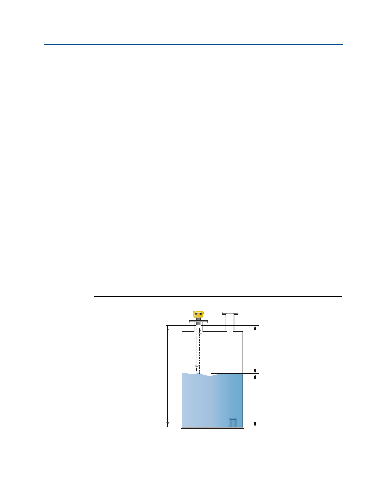
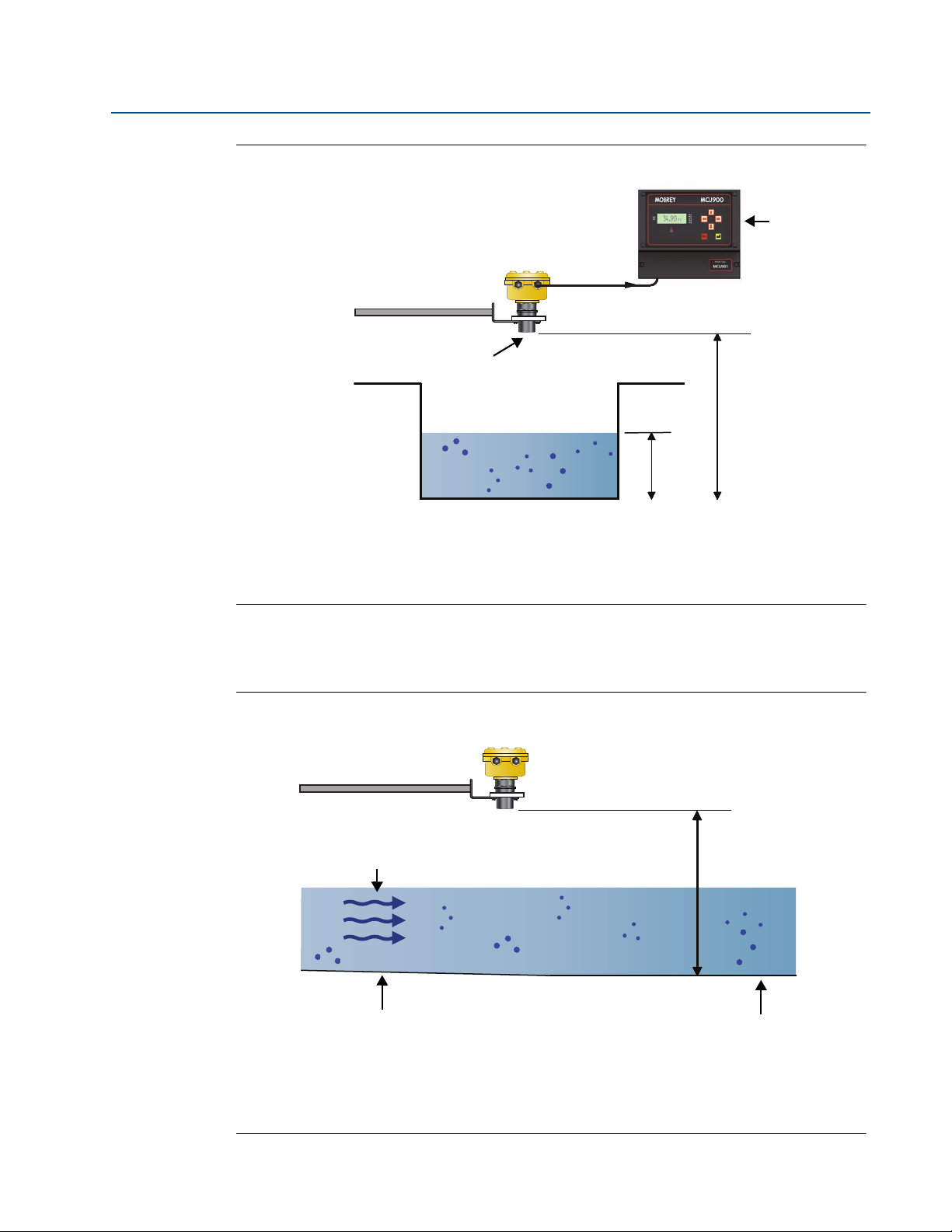
The Mobrey MSP400RH and MSP900GH ultrasonic liquid level transmitters are mounted above
a liquid and use ultrasonic pulses to continuously measure the distance to the liquid surface. The
electronics calculate the distance to the liquid level using the time delay between transmitting
and receiving signals (Figure 2-1).
When programmed with the bottom reference of the application – usually the bottom of a tank
– the transmitter calculates the liquid depth (level), and outputs the result as a 4–20 mA signal
®
and a digital HART
The MSP400RH and MSP900GH can also calculate contents volume or open channel flow, when
programmed with further application information, and then outputs the result as a
4–20 mA signal and a digital HART signal.
Figure 2-1. Typical Application using Mobrey MSP400RH and MSP900GH transmitters
signal.
A. Transmitter Bottom Reference B. Distance C. Level
3
Page 14
Section 2: Transmitter Overview
D
C
B
A
Supplied with:
1 x Cable Gland
1 x Blanking Plug
D
February 2015
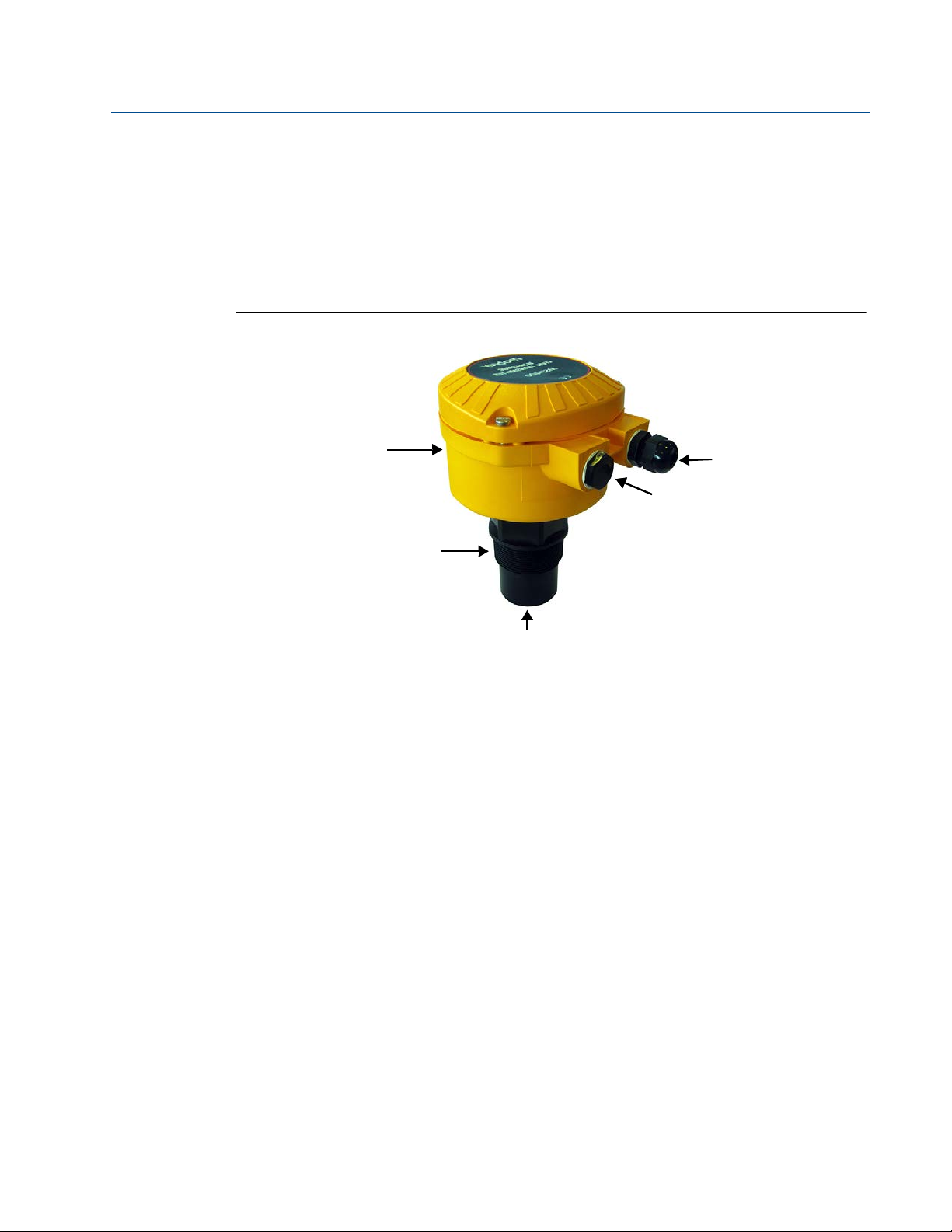
2.3 Components of the transmitter
The transmitter has a housing containing advanced electronics to generate ultrasonic pulses,
process the resultant signals, and provide a 4–20mA and HART output.
Removing the lid reveals terminals to connect a cable (not supplied) for the signal output and
an external power supply. An LCD inside the enclosure displays the selected measurement.
Programming is achieved using integral buttons or by remote communication using HART.
Figure 2-2. Features of the MSP400RH and MSP900GH transmitters
Reference Manual
IP2048/RM, Rev AA
A. Electronics Housing C. Transmitter Face
B. 2-in. Mounting Thread D. M20 Conduit Threads
2.4 System architecture
The Mobrey MSP400RH and MSP900GH are two-wire, 24 Vdc loop-powered transmitters and
can be connected to a direct current (dc) power source using two-core, shielded cable.
The output can be a 4–20 mA analog signal and a digital HART signal.
Note
It is possible to use the multi-drop function with the HART protocol. In this case,
communication is restricted to digital since the current is fixed to 4 mA.
Each transmitter can be configured locally using the membrane-buttons which are revealed
after removing the housing cover. The transmitters can be configured remotely by using a
Mobrey MCU900 Series control unit
A comprehensive specification for the Mobrey MSP400RH and MSP900GH is in the section
“Specifications” on page 63.
4
Page 15
Reference Manual
B
G
C
A
D
E
F
IP2048/RM, Rev AA
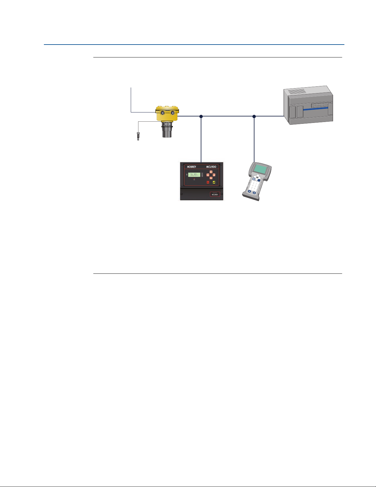
Figure 2-3. System architecture
Section 2: Transmitter Overview
February 2015
Fn
1
2
3
4
5
6
7
8
9
.
0
-
A. Mobrey MSP Series Transmitter
B. Two Relay Outputs (MSP400RH only)
C. Mobrey Remote Temperature Sensor (Optional Accessory)
D. 4–20 mA / HART Signals
E. Mobrey MCU900 Series Control Unit
F. Field Communicator
G. Control System
5
Page 16

Section 2: Transmitter Overview
February 2015
Reference Manual
IP2048/RM, Rev AA
6
Page 17

Reference Manual
IP2048/RM, Rev AA
Section 3 Installation
Safety messages . . . . . . . . . . . . . . . . . . . . . . . . . . . . . . . . . . . . . . . . . . . . . . . . . . . . . . . . . page 7
Considerations before installation . . . . . . . . . . . . . . . . . . . . . . . . . . . . . . . . . . . . . . . . . page 8
Mechanical installation . . . . . . . . . . . . . . . . . . . . . . . . . . . . . . . . . . . . . . . . . . . . . . . . . . . page 9
Electrical installation . . . . . . . . . . . . . . . . . . . . . . . . . . . . . . . . . . . . . . . . . . . . . . . . . . . . . page 16
3.1 Safety messages
Procedures and instructions in this manual may require special precautions to ensure the safety
of the personnel performing the operations. Information that raises potential safety issues is
indicated by a caution symbol ( ). The external hot surface symbol ( ) is used when a surface
is hot and care must be taken to avoid possible burns. If there is a risk of an electrical shock the
( ) symbol is used. Refer to the safety messages listed at the beginning of each section before
performing an operation preceded by this symbol.
Section 3: Installation
February 2015
Failure to follow these installation guidelines could result in death or serious injury
Make sure only qualified personnel perform the installation.
Use the equipment only as specified in this manual. Failure to do so may impair the
protection provided by the equipment.
Explosions could result in death or serious injury
Verify that the operating environment of the transmitter is consistent with the
appropriate hazardous locations certifications.
Before connecting a HART
®
-based communicator in an explosive atmosphere, make
sure the instruments in the loop are installed in accordance with intrinsically safe or
non-incendive field wiring practices.
Electrical shock could cause death or serious injury
Use extreme caution when making contact with the leads and terminals.
Any substitution of non-recognized parts may jeopardize safety. Repair, e.g. substitution of
components etc., may also jeopardize safety and is under no circumstances allowed.
7
Page 18

Section 3: Installation
February 2015
3.2 Considerations before installation
The Mobrey MSP400RH and MSP900GH transmitters can be used for level and contents volume
measurements in open or closed tanks, or for open channel flow measurements.
The transmitter must be installed in a location where it is protected from ultraviolet radiation to
prevent long term degradation of the plastics used e.g. shrouded from direct sunlight.
It is important to correctly position the transmitter for reliable ultrasonic level measurement.
For maximum accuracy and stability of the level measurement reading, the transmitter should
always be shrouded from direct sunlight and radiated heat.
The transmitter may be site-tuned to deal with most application conditions, but it is
recommended that the following guidelines be adopted where relevant.
3.2.1 Safety considerations
Guidelines
Reference Manual
IP2048/RM, Rev AA
1. Installation must be carried out by suitably trained personnel in accordance with the
applicable code of practice.
2. If the equipment is likely to come into contact with aggressive substances, it is the
responsibility of the user to take suitable precautions that prevent it from being
adversely affected, thus ensuring that the type of protection is not compromised.
Aggressive substances are acidic liquids or gases that may attack metals or solvents
that may affect polymeric materials.
Suitable precautions are regular checks as part of routine inspections, or establishing,
from the material's datasheet, that it is resistant to specific chemicals.
3. The equipment must only be cleaned with a damp cloth.
4. The equipment is not intended to be repaired by the user and is to be replaced by an
equivalent certified unit. Repairs should only be carried out by the manufacturer or
approved repairer.
5. The transmitter is double insulated, and therefore Protective Earthing is not required.
However, the cable shield/screen should be connected to a suitable ground (earth) at
one end only (see “Connecting the cable(s) to the transmitter” on page 16).
6. Note that if the equipment is used in a manner not specified by the manufacturer, the
protection afforded by the equipment may be impaired.
7. To ensure electro-magnetic compatibility in any European member state, it should not
be installed in a residential area.
Note
It is not advisable to mount the transmitter in close proximity to a source of electrical
noise such as a variable-speed drive, or other high-powered electrical device.
8
Page 19

Reference Manual
IP2048/RM, Rev AA
3.3 Mechanical installation
Guidelines
1. Mount the transmitter above the liquid surface using the 2-inch thread provided, but
not closer than 12 in. (0,3 m) to the surface. The transmitter does not detect any liquid
surface closer than 12 in. (0,3 m) to the transmitter face. (See “Mounting the
transmitter above the liquid surface” on page 11).
Optional flanges and bracket kits are available to help mounting. (See Rosemount
Measurement product data sheet IP2045 for accessory part numbers.)
2. The transmitter should be mounted vertically to ensure a good echo from the liquid
surface. The transmitter beam half angle of the is 6 degrees. (See Figure 3-1 on
page 10).
3. Obstructions in the tank, or well, may generate echoes which can be confused with the
real liquid surface echo. Obstructions within the beam angle generate strong false
echoes. Wherever possible, the transmitter should be positioned to avoid false echoes.
Section 3: Installation
February 2015
4. To avoid detecting unwanted objects in the tank or well, it is advisable to maintain a
distance of at least 1.3 in. from the center line of the transmitter for every foot (11 cm
per meter) range to the obstruction.
5. No false echoes are generated if the transmitter is located near the side of the tank or
well, and the wall is smooth and free of protrusions. However, there will still be a
reduction in the echo size. It is recommended that the transmitter be mounted no
closer than 12 in. (0,3 m) to the wall to avoid a large reduction in the echo size.
6. If the transmitter is mounted in an enclosed tank with a domed top, avoid mounting
the transmitter in the center of the tank roof because this could act as a parabolic
reflector and create unwanted echoes.
7. Avoid applications where heavy condensation could form on the transmitter face.
8. If the transmitter is mounted in a stand-off or nozzle, the transmitter face should
protrude at least 0.2 in. (5 mm) into the tank. If this is not possible, see “Mounting the
transmitter above the liquid surface” on page 11).
9. If the transmitter is used in environments where direct sunlight can cause high surface
temperatures on exposed surfaces, a sun-shade is recommended.
10. Check that the maximum liquid level will not enter the 12-in. (0,3 m) blanking zone of
the transmitter.
9
Page 20
Section 3: Installation
A
D
B
C
February 2015
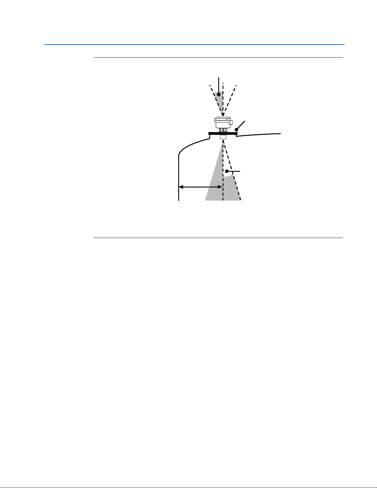
Figure 3-1. Min And Max Distances From Tank Wall
Reference Manual
IP2048/RM, Rev AA
A. Transmitter is mounted vertically (maximum deviation of 3°).
B. Use a non-metallic fitting or flange.
C. 6° beam half angle
D. 1.3 in./ft. (11 cm/m). Minimum of 12 in. (0.3 m).
3.3.1 Consider the liquid surface conditions
Guidelines
1. Foaming liquids can reduce the size of the returned echo because foam is a poor
ultrasonic reflector.
Mount an ultrasonic transmitter over an area of clear liquid, such as near the inlet to a
tank or well. In extreme conditions, or where this is not possible, the transmitter may
be mounted in a vented stilling tube provided that the inside measurement of the
stilling tube is at least 4 in. (100 mm) and is smooth and free from joints or protrusions.
It is important that the bottom of the stilling tube stays covered to prevent the ingress
of foams.
2. Avoid mounting the transmitter directly over any inlet stream.
3.3.2 In-tank effects
10
Guidelines
1. Stirrers or agitators can cause a vortex. Mount the transmitter off-center of any vortex
to maximize the return echo.
2. If stirrer blades become uncovered, they create echoes as they pass through the
ultrasonic beam. The transmitter can learn to ignore these false echoes (see page 56 or
page 93 for further information).
Page 21

Reference Manual
IP2048/RM, Rev AA
3. In tanks with rounded or conical bottoms, mount the transmitter off-center. If needed,
a perforated reflector plate can be installed on the tank bottom directly under the
transmitter center line to ensure a satisfactory return echo.
4. Avoid detecting pump casings, as the liquid falls away, by not mounting the transmitter
directly above pumps. If this is not possible, fine-tuning of the transmitter on-site may
be required.
Section 3: Installation
3.3.3 Mounting the transmitter above the liquid surface
A 2-in. thread is provided to mount the transmitter. The thread form is either BSPT or NPT, and is
clearly marked on the hexagon of the transmitter body.
Note
The Mobrey MSP400RH and MSP900GH are designed to be mounted in a non-metallic
fitting or flange. The use of metallic fittings/flanges is not recommended.
To help installation, flange accessories and bracket kits are available from Emerson Process
Management (see Product Data Sheet IP2045 for accessory part numbers). The accessory
flanges supplied are manufactured from PVC and are a full face design. Care must be taken
when installing to raised face mating flanges on the tank or vessel to prevent distortion of the
PVC flange by over-tightening the bolts.
February 2015
Bracket mounting
The bracket kit contains a stainless steel angle bracket and PVC threaded disc, which may be
used to mount the transmitter on a support over the liquid surface. See Product Data Sheet
IP2045 for accessory part numbers.
The bracket and disc dimensions are in Figure A-4 on page 69. The combined weight of bracket
and disc is 16 oz (0,5 kg). For transmitter weight, see “Specifications” on page 63.
Bracket installation procedure
1. Attach bracket to the disc using the three screws provided.
2. Attach the assembled bracket and disc to a rigid support over the liquid surface. The
bracket may be bolted to a suitable crossmember (structural section of steel).
3. Use PTFE tape on the screw thread (Figure 3-3 on page 13).
4. Insert the transmitter into the disc.
5. Tighten to a torque of 1.5 lbf.ft. (2 Nm) using the hexagon. Do not use the transmitter
housing to tighten.
11
Page 22
Section 3: Installation
B
C
A
Note: Combined weight of bracket
and disc is 16 oz (0,5 kg).
February 2015
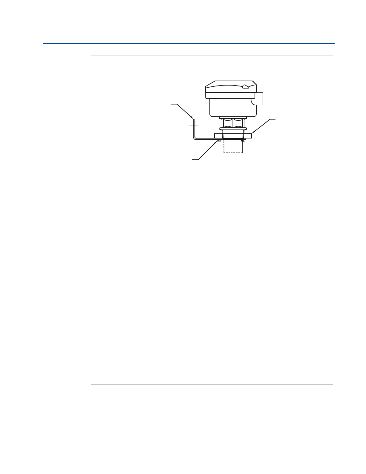
Figure 3-2. Mounting the transmitter using a bracket kit
A. Stainless steel bracket
B. No. 4X 13 long self tap screw (3 positions), carbon steel (zinc plated)
C. PVC disc
Reference Manual
IP2048/RM, Rev AA
Installing in a tank with a nozzle or stand-off
Installation procedure
1. Use PTFE tape on the screw thread of the transmitter (Figure 3-3).
2. If the tank has a flanged nozzle or stand-off:
a. Attach the transmitter to a non-metal instrument flange using the threaded
connection. Tighten to a torque of 1.5 lb-ft (2 N-m) using the transmitter’s hexagon.
b. The instrument (accessory) flanges supplied by Emerson Process Management are
manufactured from PVC and are a full face design. Care must be taken when installing
to a raised face mating flange on the tank or vessel to prevent distortion of the PVC
flange by over-tightening the bolts.
c. Ensure the gasket is sitting correctly on the tank flange.
d. Lower the assembled transmitter and instrument flange onto the tank flange, and
secure with appropriate bolting to a suitable torque for the flanges.
If mating to a raised face flange (RF) on the tank nozzle or stand-off, tighten to a
maximum torque of 10 lb-ft (13.6 N-m).
3. If the tank has a threaded nozzle or stand-off:
a. Attach the transmitter to the nozzle/stand-off using the threaded connection.
b. Tighten to a torque of 1.5 lb-ft (2 N-m) using the transmitter’s hexagon.
Note
If the transmitter face does not protrude into the vessel, note the dimensions in
Table 3-1 on page 3-13 for Figure 3-3, and ensure that the nozzle/vessel weld is smooth
and free from internal weld beads or other projections.
12
Page 23
Reference Manual
PTFE
L
D
Tighten To A Torque Of 1.5 lbf.ft.
(2 Nm) Using The Hexagon. Do
Not Use The Housing To Tighten
Use Non-metallic
Fitting / Flange
IP2048/RM, Rev AA
Section 3: Installation
February 2015
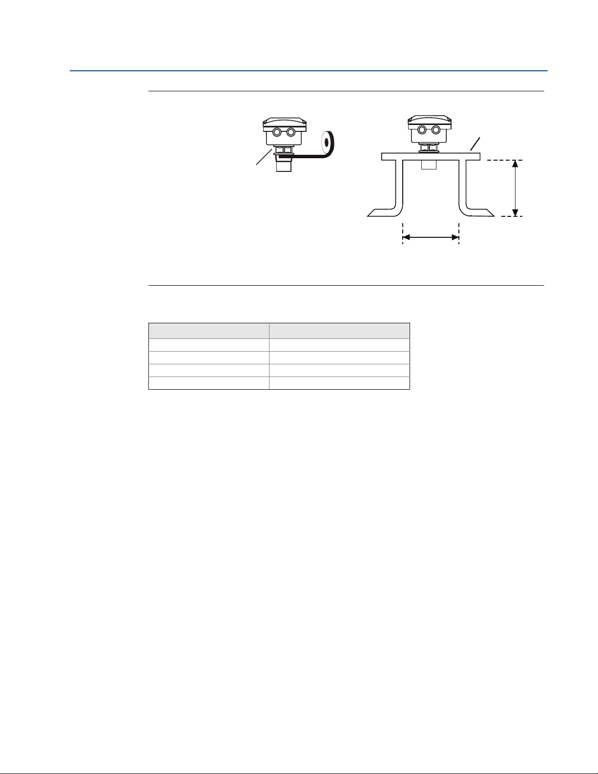
Figure 3-3. Mounting the transmitter using a nozzle/stand-off
D. See dimension D in Table 3-1.
L. See dimension L in Table 3-1.
Table 3-1. Nozzle diameter size and maximum length
Nozzle Diameter Size (D) Maximum Nozzle Length (L)
DN50 (2 in.) 4 in. (100 mm)
DN80 (3 in.) 6.3 in. (160 mm)
DN100 (4 in.) 6.3 in. (160 mm)
DN125 (5 in.) 11.8 in. (300 mm)
3.3.4 Open channel flow installations
There are normally two distinct parts to an open channel flow measurement system; the
primary element (flow structure) and the secondary element (Head measurement instrumentation). For accurate open channel flow measurement, both parts of the system must be correctly
installed.
This section explains the important parts of installing the transmitter (secondary element). The
flow structure (primary element) installation can be referenced in the British (BS3680) or ISO
International standards.
Positioning of the transmitter is critical, and should be the correct distance upstream from the
flow structure as stated in the relevant standard for your country. For example, in the ISO
standards, the distance should be four to five times the maximum height of the water (H
a thin plate weir, or three to four times H
transmitter’s front face should be positioned at a height equal to the maximum flow depth plus
14 in. (0,35 m).
for a flume. For optimum accuracy, the
max
max
) for
13
Page 24
Section 3: Installation
A
B
C
D
C
D
B
A
February 2015
Figure 3-4. Choosing the height position above a flow
Reference Manual
IP2048/RM, Rev AA
A. Transmitter front face
B. Hmax
C. Hmax + 14 in.
D. Mobrey MCU900 Series control unit
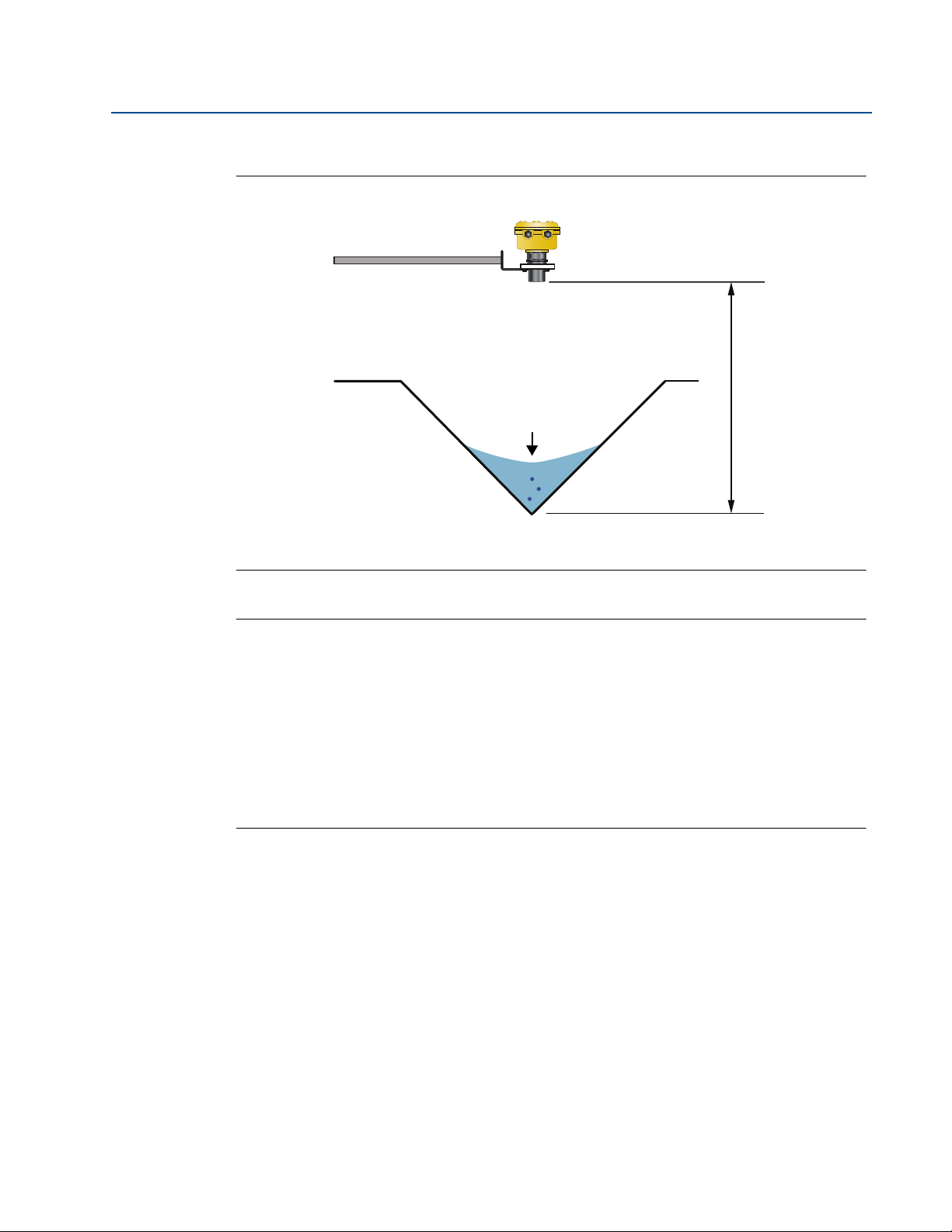
It is important that the bottom reference of the transmitter should be related to the datum of
the primary measuring device (see Figure 3-6).
Figure 3-5. Transmitter bottom reference for a flume or weir
14
A. Transmitter bottom reference
B. Primary element (e.g. flume, weir) invert
C. Approach channel
D. Flow direction
Page 25
Reference Manual
B
A
IP2048/RM, Rev AA
Section 3: Installation
February 2015
Figure 3-6. Transmitter bottom reference for a ‘V’ notch weir
A. Transmitter bottom reference (i.e. true invert)
B. Meniscus Level
Note
The transmitter should be free from a situation where it is likely to 'drown' (refer to
relevant Standard for further information).
The MSP400RH and MSP900GH have the option of a Remote Temperature Sensor for
temperature compensation (see “Remote temperature sensor” on page 19).
The temperature sensor should be mounted in a location where it can get an accurate
air temperature measurement and is protected from sunlight.
If the flow structure permits, mount the transmitter within the flow channel or
chamber. Shroud the transmitter from direct sunlight for maximum accuracy and
stability.
15
Page 26

Section 3: Installation
February 2015
3.4 Electrical installation
3.4.1 Connecting the cable(s) to the transmitter
The Mobrey MSP400RH and MSP900GH are two-wire loop-powered transmitters accepting
power supplies as follows:
MSP400RH:12 to 40 Vdc (non-hazardous area only)
MSP900GH:12 to 40 Vdc (non-hazardous area) or 12 to 30 Vdc (hazardous area)
Note
To comply with the CSA approval, a transmitter must be powered from a Mobrey
MCU900 Series control unit, or a class 2 or separate extra-low voltage (SELV) source.
Other devices may reset if connecting the transmitter to a multi-drop system while the
loop is powered. De-energize the loop to avoid devices being reset
Each transmitter is supplied with two cable entries. A suitable conduit system or cable gland
must be used to maintain the weather-proof rating and hazardous area protection. Any unused
entry must be sealed with a suitably rated blanking plug.
Reference Manual
IP2048/RM, Rev AA
A two-core, shielded/screened cable is required for external power supply and output signal
connections. The cable is not supplied.
Connect the cable(s) to the transmitter
1. Make sure that the power supply is disconnected.
2. Undo the three cover screws and then lift the transmitter housing cover.
3. Pass the cable through the cable gland/conduit.
4. Connect the cable wires:
a. For the MSP400RH, see “Connecting the cable wires to the MSP400RH” on page 17.
b. For the MSP900GH, see “Connecting the cable wires to the MSP900GH” on page 18.
5. Connect the cable shield/screen to a suitable ground (earth) at one end only.
6. Replace the cover, tighten the cable gland, and connect the power supply.
What to do after completing the cabling
To maintain the weather-proof rating and hazardous area protection of the transmitter, ensure
all cable glands, blanking plugs, and seals are in good condition.
Check that the cover seal is in good condition, and not twisted or misaligned in the seal location
groove. When replacing the cover, tighten the three cover screws evenly to exert uniform
pressure on the cover seal.
16
Page 27
Reference Manual
Min. 12 Vdc
Ø4 to 8 mm
(0.15 to 0.31 in.)
Twisted-pair, Screened
Min. 0.22mm
2
(24 SWG / 23 AWG)
Max. 1.5mm
2
(16 SWG / 18 AWG)
0 Vdc
Max. 3000 m (9750 ft.)
+12 to 30 Vdc
IP2048/RM, Rev AA
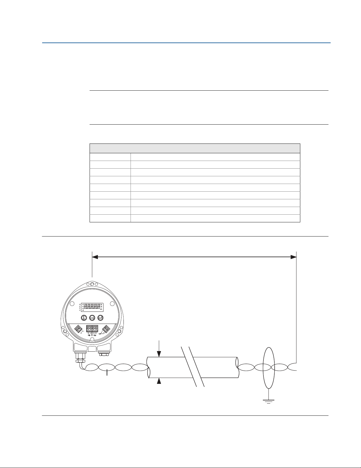
3.4.2 Connecting the cable wires to the MSP400RH
Connect the cable wires to the transmitter as shown in Figure 3-7. See also “Wiring to allow
HART communications” on page 19 if HART digital communications is required.
Note
Make sure the power supply is off when connecting the transmitter.
The MSP400RH is not intrinsically safe, and is for use in non-hazardous (ordinary
location) installations only.
Table 3-2. Terminal connections on the MSP400RH
Connections
Terminal 1 24 Vdc
Terminal 2 0 Vdc
Terminal 3 RL1 (SPST) - see “Relays” on page 18
Terminal 4 RL1 (SPST) - see “Relays” on page 18
Terminal 5 RL2 (SPST) - see “Relays” on page 18
Terminal 6 RL2 (SPST) - see “Relays” on page 18
Terminal 7 Remote temperature sensor (if used) - see page 19
Terminal 8 Remote temperature sensor (if used) - see page 19
Earth Screen Connect the cable shield/screen to ground (earth) in the control room
Section 3: Installation
February 2015
Figure 3-7. Wiring Diagram for The MSP400RH
17
Page 28

Section 3: Installation
February 2015
Relays
The MSP400RH has two integral relays which may be used for fault indication or control
purposes. These relays are for light duty and should be used as signal relays only, with control
functions being performed by external control relays.
Relay 2 is defaulted as a 'fault' relay - normally energized - but may be re-configured
on-site as a set-point relay if required.
Relay status indicators are on the LCD inside the housing (see “Display and
push-buttons” on page 21.)
3.4.3 Connecting the cable wires to the MSP900GH
The MSP900GH is for intrinsically safe installations.
Note
Make sure the power supply is off when connecting the transmitter.
Installation in a non-hazardous (ordinary location) area
Reference Manual
IP2048/RM, Rev AA
Connect the cable wires to the transmitter as shown in Figure 3-8 on page 19. See also “Wiring
to allow HART communications” on page 19 if HART digital communications is required.
Installation in a hazardous area
Connect the cable wires to the transmitter as shown in Figure 3-8 on page 19. See also “Wiring
to allow HART communications” on page 19 if HART digital communications is required.
When the MSP900GH is powered by a Mobrey MCU900 Series control unit, no safety barriers are
required as the output from the control unit is Intrinsically Safe.
If powering the transmitter from any other power supply, ensure a suitable intrinsically safe
barrier is fitted in the non-hazardous (safe) area. The barrier must be chosen such that its output
parameters Uo, Io and Po are less than Ui, Ii and Pi of the transmitter (see Appendix B: Product
Certifications). The sum of the capacitance and the inductance of the transmitter and the
connecting cable fitted must not exceed the maximum specified for the barrier chosen.
Note
Make sure that the instruments in the loop are installed according to intrinsically-safe
field wiring practices and control drawings, when applicable.
Table 3-3. Connections for The MSP900GH
Connections
Terminal 1 24 Vdc
Terminal 2 0 Vdc
Terminal 7
Terminal 8
Earth Screen Connect the cable shield/screen to ground (earth) in the control room.
(1) See “Remote temperature sensor” on page 19 for further information.
(1)
(1)
Remote temperature sensor (if used).
Remote temperature sensor (if used).
18
Page 29
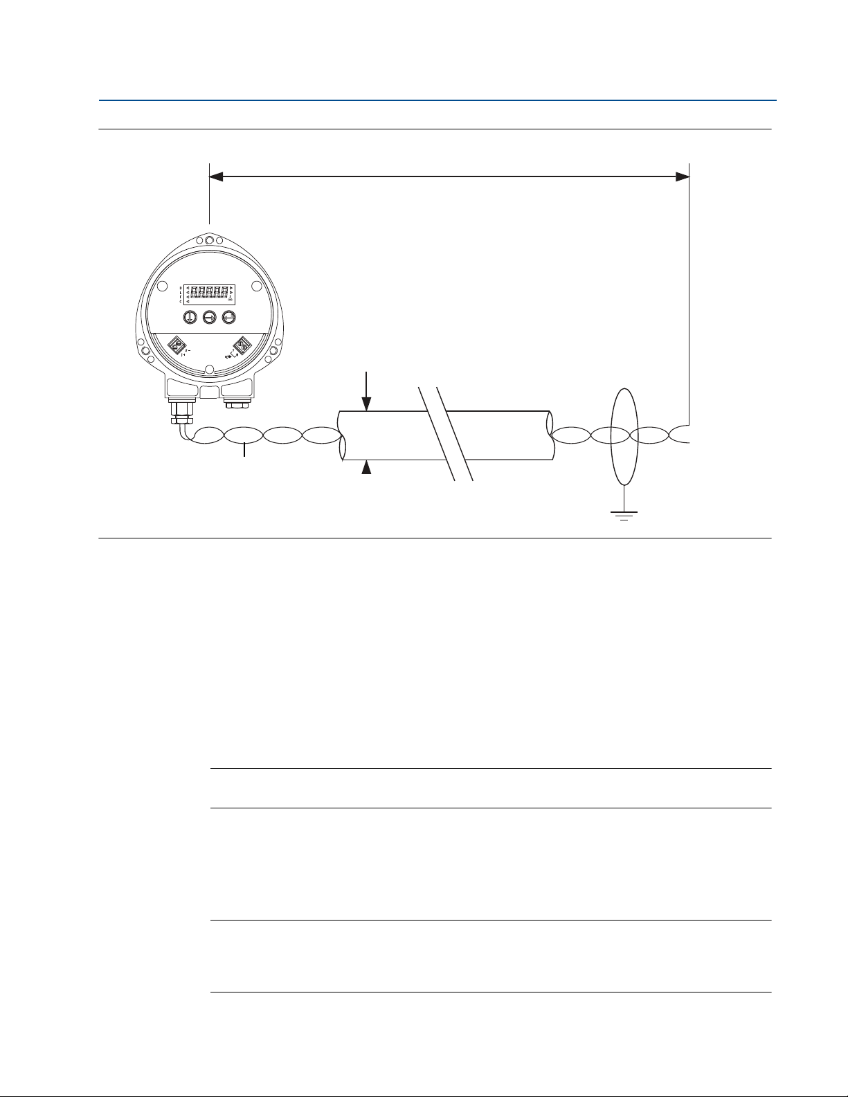
Reference Manual
Min. 12 Vdc
Ø4 to 8 mm
(0.15 to 0.31 in.)
Twisted-pair, Screened
Min. 0.22 mm
2
(24 SWG / 23 AWG)
Max. 1.5 mm
2
(16 SWG / 18 AWG)
0 Vdc
Max. 3000 m (9750 ft.)
+12 to 40 Vdc
(Non I.S. Application)
or
+12 to 30 Vdc From
Protective Barrier
(I.S. application.)
IP2048/RM, Rev AA
Figure 3-8. Wiring diagram for the MSP900GH
Section 3: Installation
February 2015
3.4.4 Remote temperature sensor
The MSP400RH and MSP900GH accept input from a Mobrey Remote Temperature Sensor
(see Product Data Sheet IP2045 for accessory part numbers).
This is a thermistor-based temperature sensor designed for use with the MSP400RH and
MSP900GH.
Full installation instructions are supplied with the temperature sensor, but it should be mounted
out of direct sunlight in a position so that it can give a representative reading of the air
temperature between the liquid surface and the transmitter.
Note
Do not connect any other temperature sensor to the MSP400RH or the MSP900GH.
3.4.5 Wiring to allow HART communications
If HART communications is required, a 250 Ohms (minimum), 0.25 W load resistor must be
installed in the loop. (See “Dimension drawings” on page 68).
Note
When the transmitter is used with a Mobrey MCU900 Series control unit, there is no
need to install an external load resistor in the loop because a suitable resistor is built in
to the control unit.
19
Page 30

Section 3: Installation
February 2015
Reference Manual
IP2048/RM, Rev AA
If the transmitter is being supplied through a safety barrier, ensure the type chosen will pass
HART information.
After the load resistor is installed, a Field Communicator can be connected across the load
resistor. It is the responsibility of the installer to ensure that any Field Communicator used in the
hazardous area is suitably certified.
Note
Make sure that the instruments in the loop are installed according to intrinsically-safe
field wiring practices and control drawings, when applicable.
3.4.6 Lightning / Surge protection and other loop devices
If the area is prone to lightning strikes or voltage surges, a suppressor device may be installed
between the transmitter and the control unit.
If an additional loop-powered device or separately powered device is included in the two-wire
loop, ensure the transmitter receives a minimum voltage of
12 Vdc. (See “Dimension drawings” on page 68).
20
Page 31

Reference Manual
IP2048/RM, Rev AA
Section 4 Starting up
Overview . . . . . . . . . . . . . . . . . . . . . . . . . . . . . . . . . . . . . . . . . . . . . . . . . . . . . . . . . . . . . . . page 21
Programming . . . . . . . . . . . . . . . . . . . . . . . . . . . . . . . . . . . . . . . . . . . . . . . . . . . . . . . . . . . page 23
Final checks . . . . . . . . . . . . . . . . . . . . . . . . . . . . . . . . . . . . . . . . . . . . . . . . . . . . . . . . . . . . . page 43
Power failure . . . . . . . . . . . . . . . . . . . . . . . . . . . . . . . . . . . . . . . . . . . . . . . . . . . . . . . . . . . . page 43
4.1 Overview
Mobrey MSP400RH and MSP900GH ultrasonic liquid level transmitters are operated from a
menu of parameters, each held in a specific memory location within the transmitter. The
memory locations may be pictured as a matrix, and navigated for programming the instrument
and steps.
using
The Integral Display Menu structure is shown in Appendix C: Integrated Display Menus.
Section 4: Starting up
February 2015
The transmitter is pre-programmed at the factory with a value in each parameter location so
that when the power is first applied, the transmitter gives a sensible reading. Default values are
listed in Appendix D: Mobrey MCU900 Series.
The MSP400RH and MSP900GH are HART-enabled, allowing remote communications with the
instrument. The transmitter can be programmed using a suitable HART-compatible master, or
locally using the push-buttons provided inside the transmitter.
Note
This section details the local programming. Refer to Appendix F: Configuring Using
HART if using a Mobrey MCU900 Series control unit or a Field Communicator.
4.1.1 Display and push-buttons
The integral display allows up to five characters. In running mode, the Primary Value (PV)
measurement is displayed. In programming mode, data is displayed to assist with
programming.
To the left of the main display are four arrow icons; one will be illuminated to indicate the
selected duty.
To the right of the PV display on The MSP400RH are two arrow icons that indicate the status of
the transmitter relays. When illuminated, they indicate the relay contact is closed.
Under the PV display is a text string indicating the units of measurement. The transmitter will
illuminate only those characters applicable to the units of measurement chosen.
To the right of the text string is an echo received icon. It is made up of three arc segments that
continuously indicate the strength of the echo received (minimum, average, and good).
21
Page 32

Section 4: Starting up
Green
Button
Red
Button
Alarm
Faul t
Blue
Button
D
L
F
C
February 2015
Figure 4-1. Display and push-buttons
Reference Manual
IP2048/RM, Rev AA
4.1.2 Power up
When the power is turned on, the transmitter takes several seconds to initialize. The display will
run a set-up routine, first illuminating all display characters, and then showing the software
revision number. Finally, a full set of zeros is displayed while the microprocessor identifies the
correct return echo. After these checks are complete, the display indicates the live
measurement based upon the factory default values in memory.
On a new instrument aimed at a good target, the transmitter calculates a level reading based
upon the default value for the bottom reference.
The duty icon against the letter L on the top plate, and the RL2 icon on The MSP400RH, will be
illuminated. The RL1 icon on the MSP400RH may be illuminated, depending on the level
calculated by the transmitter at this time.
The transmitter is now ready to be set-up with details of the application.
The transmitter may be programmed prior to, or after, installation. All programmed data is
retained in the transmitter memory after the power is turned off.
22
Page 33

Reference Manual
IP2048/RM, Rev AA
4.1.3 Before programming
Important notes to help you program the transmitter
Do not allow rain, or water, to enter the transmitter during programming or the circuit
boards may be damaged.
See the instructions below on how to use the push-buttons to navigate through the
programming menu and select or enter application data.
Push the buttons firmly, but not too hard, to avoid damaging the circuit boards. Also, to
avoid entering incorrect data, do not push the buttons too fast.
Holding down the green button scrolls through any option list.
Pressing the red button at any time will return you to the previous level in the menu.
If the red button is pressed after new data has been entered, the new data will
automatically be saved.
The transmitter has a “re-set default values” routine that reloads the transmitter
memory with the factory default values. This will clear the memory of any previous data
entered on site.
Section 4: Starting up
February 2015
4.2 Programming
Menu structures for this section are in Appendix C: Integrated Display Menus (page 75).
If using a HART Master Device for programming the MSP400RH or the MSP900GH, refer to the
following sections for menu structures and parameters:
Appendix D: Mobrey MCU900 Series (page 81)
Appendix E: Field Communicator (page 85)
Appendix F: Configuring Using HART (page 89)
4.2.1 Overview
Transmitter programming is most easily accomplished by first selecting the duty that the
transmitter is to perform. After a duty is selected (see below), a “mini-wizard” programming
assistant is invoked that asks only for information relevant to the selected duty. Entered data
allows the mini-wizard to populate relevant parameters with application specific data and select
the next step required to configure the transmitter.
Note
It is advised to enter the “dutY” menu when programming the transmitter, initiating
the mini-wizard to assist with programming.
After programming is complete, the data entered or calculated by the transmitter can be
reviewed by going through the menu using the green button
This is a manual navigation of
the menus, and all menus are shown regardless of the duty selected; the mini-wizard is only
initiated when a duty is selected. Ignore menus that do not relate to your application.
23
Page 34

Section 4: Starting up
February 2015
4.2.2 Selecting the duty
Screen display: dutY
Factory default setting: Level
The arrow icon on the left side of the PV display indicates the selected duty. The MSP400RH and
MSP900GH may be programmed to perform one of four duties:
1. Distance measurement.
2. Level measurement (factory default setting).
3. Flow measurement.
4. Contents (Volume) measurement.
Note
This menu option is in the programming menu. See Figure C-1 on page 76 for a map of
the menu structure and how to access the menu options.
Reference Manual
IP2048/RM, Rev AA
To change the duty
1. Press the green button to enter the menu system from the PV display (see the note
above.) The display indicates “dutY”.
2. Press the blue button
duty: “LEVEL”, “Flo”, “cont”, or “diSt”.
3. If the duty is correct, press the red button
next menu option.
4. Press the blue button
now be edited.
5. Press the green button
6. Press the blue button
7. If the new duty is correct, press the red button
next menu option.
8. If the new duty is incorrect, press the blue button
option “dutY” re-appears; re-start at step (b) or press
to enter the “dutY” menu and display the presently selected
and then the green button to get to the
to start the editing mode. The duty flashes to indicate it may
repeatedly to scroll through the list of duties.
to confirm the duty. The flashing then stops.
to save. The display will change to the
to exit to the menu. The menu
to get to the next menu option.
24
Page 35

Reference Manual
IP2048/RM, Rev AA
4.2.3 Selecting the units of measurement
Screen display: unitS
Factory default setting: m (metric) or ft (Imperial)
The transmitter is pre-programmed with selectable measurement units for each of the duties:
1. Distance and Level measurement: m, ft, or in
3
2. Flow measurement: l/s, l/m, m
3. Contents measurement: l, m3, gal, or ft3
Note
The factory default units of measurement are dictated by the model part number
(see ordering information tables in Product Data Sheet IP2045).
A Metric unit can be re-configured to be an Imperial unit, or vice-versa, by changing the
base units (b.unit) of the transmitter. See “Changing the base units” on page 60.
Changing base units after programming the transmitter will cause all
programmable data to be overwritten with factory default values.
The unitS menu option is in the programming menu. See Figure C-1 on page 76 for a
map of the menu structure and how to access all the menu options.
/hr, gal/m, m ga, ft3/m (cfm), or ft3/hr
Section 4: Starting up
February 2015
To change the measurement units
1. If entering the menu system from the PV display, press the green button repeatedly
until the “unitS” menu option is indicated (see note above.)
2. Press the blue button
indicated on the bottom display line.)
3. If the units are correct, press the red button
next menu option.
4. Press the blue button
may be edited.
5. Press the green button
6. Press the blue button
7. If the new units are correct, press the red button
8. If the new units are incorrect, press the blue button
option “unitS” re-appears; re-start at step (2) or press
Note
When using the green button to scroll through the measurement units, allow three
seconds after each button press for the transmitter to check and display the selection.
After changing units, a scaling factor (see “K-factor for the flow law” on page 32) needs
to be edited to see the correct PV.
to enter the “unitS” menu. (The presently selected units are
and then the green button to exit to the
to start the editing mode. The present units flash to indicate it
repeatedly to scroll through the list of units.
to confirm the new units. The flashing stops.
to save and get to the next menu.
to exit to the menu. The menu
to get to the next menu.
25
Page 36

Section 4: Starting up
B
C
A
February 2015
4.2.4 Setting the correct bottom reference
Screen display: b.rEF
Factory default value: 11
The transmitter leaves the factory with the bottom reference pre-programmed to the
maximum range of the instrument 36 ft. (11 m).
Note
It is important to not enter a value greater than the maximum range of the transmitter,
which is 36 ft. (11 m).
Figure 4-2. Transmitter bottom reference
Reference Manual
IP2048/RM, Rev AA
A. Transmitter bottom reference B. Distance-to-target C. Depth (level)
Note
This menu option is in the programming menu. See Figure C-1 on page 76 for a map of
the menu structure and how to access the menu options.
To change the bottom reference
1. If entering the menu system from the PV display, press the green button repeatedly
until the “b.rEF” menu option is indicated (see note above.)
2. Press the blue button
reference (b.rEF) value.
3. If this value is correct, press the red button
next menu option.
4. Press the blue button
can now be edited.
5. Press the green button
6. Press the blue button
edited.
to enter the “b.rEF” menu and display the present bottom
and then the green button to get to the
to start the editing mode. The first digit flashes to indicate it
repeatedly to edit the flashing digit.
to select the next digit. The digit flashes to indicate it can be
26
Page 37

Reference Manual
IP2048/RM, Rev AA
Section 4: Starting up
February 2015
7. Repeat steps (5) and (6) until the last digit is flashing, and edited as required.
8. Press the blue button
now be flashing.
9. If the new b.rEF value is correct, press the red button
change to the next menu option.
10. If the new value is incorrect, press the blue button
re-appears; re-start at step (2) or press
Note
If the saved duty is Flow or Contents, the next menu option is “ProF”
(see “Selecting a profile” on page 27).
If the saved duty is Level or Distance, the next menu option is “4”
(see “Setting the 4 mA point” on page 36).
A useful feature at this stage is that the transmitter can be used as an electronic tape
measure. With an empty tank or vessel, the transmitter will read the distance to the
bottom of the tank. This distance can be noted and later used when setting b.rEF.
4.2.5 Selecting a profile
Screen display: ProF
Factory default value: Lin
This menu is offered if the selected duty is Contents (Volume) or Flow, or is shown when
manually navigating the menu system - this section can be ignored if the selected duty is Level or
Distance.
to confirm the new b.rEF value. None of the digits should
to save. The display will
to exit to the menu. The “b.rEF”
for the next menu.
The transmitter is pre-programmed with popular profiles that are mathematical formulas to
convert (scale) a linear level reading to a flow or volumetric PV. Once converted (scaled), the
4–20 mA Output and the Integral Display will operate according to the flow or volumetric PV.
The profile options are described in the following sections:
“Contents (volume) measurement” on page 27
“Flow measurement” on page 28
Contents (volume) measurement
Lin Linear (factory default setting)
H.CYL.F Horizontal cylinder on it' side with flat ends
SPH. Spherical vessel
H.CYL.D Horizontal cylinder on its side with dished ends
Note
This menu option is in the programming menu. See Figure C-1 on page 76 for a map of
the menu structure and how to access the menu options.
27
Page 38

Section 4: Starting up
February 2015
To change the contents profile
1. If entering the menu system from the PV display, press the green button repeatedly
Reference Manual
IP2048/RM, Rev AA
until the “ProF” menu option is indicated (see note on previous page).
2. Press the blue button
to enter the “ProF” menu and display the present profile
selection.
3. If the selected profile is correct, press the red button
option “ProF” re-appears. To get to the next menu, press
to exit to the menu. (The menu
4. Press the blue button to start the editing mode. The selected profile flashes to
indicate it can now be edited.
5. Press the green button
6. Press the blue button
7. If the new profile is correct, press the red button
repeatedly to scroll through the list of profiles (see above.)
to confirm the new profile. (The flashing stops.)
to save. The display will change to
the next menu option.
8. If the new profile is incorrect, press the blue button
re-appears; re-start at step (2) or press
for the next menu.
to exit to the menu. The “ProF”
Note
If the saved profile is “Lin”, the next menu option is “SCALE”
(see “K-factor for the flow law” on page 32).
If another contents profile is saved, the next menu is “Cont @ max”
(see “Maximum contents (volume) entry” on page 35).
Flow measurement
Table 4-1 lists the options that select a standard flow structure for the profile and the conversion
(scale) factors used to obtain the flow PV.
There are two other profiles:
SPEC.P (Special Plotted)
This option is only visible when the transmitter is configured using a HART Master
(e.g. a Mobrey MCU900 Series control unit).
SPEC.C (Special Calculated)
This option is used when a standard profile is not available from the transmitter’s
library. A power factor and a K-factor can be edited for an unsupported flow structure,
or to allow for imperfections in a standard flow structure. (See “Power Factor for the
Flow Law” on page 31 and “K-factor for the flow law” on page 32).
Note
This menu option is in the programming menu. See Figure C-1 on page 76 for a map of
the menu structure and how to access the menu options.
28
Page 39

Reference Manual
IP2048/RM, Rev AA
Section 4: Starting up
February 2015
To change the flow profile
1. If entering the menu system from the PV display, press the green button repeatedly
until the “ProF” menu option is indicated (see note on previous page).
2. Press the blue button
to enter the “ProF” menu and display the present profile
selection.
3. If the selected profile is correct, press the red button
option “ProF” re-appears. To get to the next menu, press
to exit to the menu. (The menu
4. Press the blue button to start the editing mode. The selected profile flashes to
indicate it can now be edited.
5. Press the green button
repeatedly to scroll through the list of profiles (see Table 4-1
on page 4-30.)
6. Press the blue button
7. If the new profile is correct, press the red button
to confirm the new profile. (The flashing stops.)
to save. The display changes to the
next menu option.
8. If the new profile is incorrect, press the blue button
re-appears; re-start at step (2) or press
for the next menu.
to exit to the menu. The “ProF”
Note
The next menu option will depend upon the flow profile chosen:
3/2 or 5/2: the transmitter will automatically calculate the Power factor and only
requires the K factor to be entered. (see “K-factor for the flow law” on page 32).
Manning: the next menu option is “LEUEL @ max”
(see “Maximum level entry” on page 33).
Parshall, FF, or FP: the transmitter will automatically calculate the appropriate Power
factor and K factor, and will set the 4 mA point at zero flow and the 20 mA point at
maximum flow. (See “Setting the output damping” on page 38).
29
Page 40

Section 4: Starting up
February 2015
Reference Manual
IP2048/RM, Rev AA
Table 4-1. Profile options for flow
Hmax Scale Factor
Power
(2)
Fac tor
(3)
1.5 (User)
(3)
2.5 (User)
(3)
(User)
(3)
Options Flow Structures
Metric
(m)
Imperial
(ft/in.)
Metric
3
(m
/hr)
3/2 Flume 3/2 flow law - (User)
5/2 V-Notch 5/2 flow law - (User)
mann Manning formula - (User)
Imperial
(2)
(GPM)
(3)
(3)
(3)
(User)
(User)
(User)
PAr 01 1 inch Parshall flume 0.75 2.5 217.3 151.7 1.55 17.9 87.3
PAr 02 2 inch Parshall flume 0.75 2.5 434.6 303.4 1.55 50.7 215
PAr 03 3 inch Parshall flume 0.75 2.5 635.5 445.2 1.547 125 516
PAr 06 6 inch Parshall flume 0.75 2.5 1372 924.5 1.58 389 1750
PAr 09 9 inch Parshall flume 0.75 2.5 1927 1378 1.53 882 3980
PAr 1 1 ft. Parshall flume 0.75 2.5 2487 1795 1.522 1610 7240
PAr 1.5 11/2 ft. Parshall flume 0.75 2.5 3803 2693 1.538 2440 11000
PAr 2 2 ft. Parshall flume 0.75 2.5 5143 3590 1.550 3290 14900
PAr 3 3 ft. Parshall flume 0.75 2.5 7863 5386 1.566 5010 22600
PAr 4 4 ft. Parshall flume 0.75 2.5 10630 7181 1.578 6750 30500
PAr 5 5 ft. Parshall flume 0.75 2.5 13440 8976 1.587 8510 38400
PAr 6 6 ft. Parshall flume 0.75 2.5 16280 10770 1.595 10300 46400
PAr 8 8 ft. Parshall flume 0.75 2.5 22010 14360 1.607 13900 62600
PAr 10 10 ft. Parshall flume 0.75 2.5 26862 17672 1.6 20700 89200
(4)
FF01
FF02
FF03
FF04
FF05
FF06
FF07
FF08
FF09
FF10
FF11
FF12
FF13
FF14
FF15
FF16
FF17
FF18
FF19
FF20
FF21
FF22
FF2 3
FP01
FP02
FP03
FP04
FP05
FP06
FP07
(1) Where entries do not say “(User)”, the 20 mA Point (Upper Range Value) is automatically set to the value in the meters (m) or feet/inches ( ft./in.) column depending
on the selected Base Units. The 4 mA Point (Lower Range Value) is automatically set to 0.
(2) If the Base Units are meters (m), the flow units are m3/hour. Otherwise, flow units are gal/m (GPM). The gallons are US gallons.
(3) Where shown, “(User)” indicates that the user is required to input the appropriate data.
(4) FF and FP flume options require the Base Units to be meters (m). See “Changing the base units” on page 60 if a change of Base Units is required.
Flume Flat 1 (m) 0.102 134.79 1.5 9
(4)
Flume Flat 2 (m) 0.191 178.27 1.5 36
(4)
Flume Flat 3 (m) 0.267 313.42 1.5 90
(4)
Flume Flat 4 (m) 0.406 541.72 1.5 360
(4)
Flume Flat 5 (m) 0.635 811.11 1.5 900
(4)
Flume Flat I 0.200 132.2 1.5 30
(4)
Flume Flat II 0.250 177.7 1.5 60
(4)
Flume Flat III 0.300 217.58 1.5 90
(4)
Flume Flat III bis 0.3333 328.35 1.5 200
(4)
Flume Flat III ter 0.400 272.0 1.5 200
(4)
Flume Flat IV 0.400 352.17 1.5 180
(4)
Flume Flat V 0.500 442.93 1.5 360
(4)
Flume Flat V bis 0.400 400.5 1.5 320
(4)
Flume Flat VI 0.540 499.06 1.5 720
(4)
Flume Flat VII 0.700 623.7 1.5 1080
(4)
Flume Flat VIII 0.600 881.16 1.5 1440
(4)
Flume Flat VIII bis 0.666 798.0 1.5 1500
(4)
Flume Flat IX 0.800 1065.2 1.5 1800
(4)
Flume Flat IX bis 0.733 814.8 1.5 1700
(4)
Flume Flat X 0.867 1322.3 1.5 3600
(4)
Flume Flat X bis 1.200 1609.0 1.5 7500
(4)
Flume Flat X ter 0.959 1064.9 1.5 3500
(4)
Flume Flat XI 1.200 1651.0 1.5 7200
(4)
Flume Parabolic 1 0.200 15879 2.3 20
(4)
Flume Parabolic 2 0.250 17591 2.3 40
(4)
Flume Parabolic 3 0.310 11646 2.2 90
(4)
Flume Parabolic 4 0.380 13670 2.2 180
(4)
Flume Parabolic 5 0.460 9802.7 2.1 360
(4)
Flume Parabolic 6 0.600 11368 2.1 720
(4)
Flume Parabolic 7 0.800 12228 2.1 1400
20 mA Point
Metric
(m)
(3)
(3)
- -
Imperial
(ft/in.)
(User)
(User)
(1)
(3)
(3)
30
Page 41

Reference Manual
IP2048/RM, Rev AA
4.2.6 Power Factor for the Flow Law
Screen display: P.FACt
Factory default value: 1.000
This menu is offered if the selected duty is Flow and a profile (e.g. “SPEC.C”) requires the
manual editing of a power factor in the formula:
Flow Q = kh* (where * = the power factor)
The transmitter is pre-programmed with appropriate power factors for many standard flow
profiles, and will automatically select the appropriate factor (See Table 4-1 on page 4-30).
Alternatively, the power factor may be edited to suit a specific flow structure.
Note
This menu option is in the programming menu. See Figure C-1 on page 76 for a map of
the menu structure and how to access the menu options.
To change the power factor
Section 4: Starting up
February 2015
1. If entering the menu system from the PV display, press the green button repeatedly
until the “P.FACt” menu option is indicated (see note above.)
2. Press the blue button
to enter the “P.FACt” menu and display the present power
factor.
3. If the power factor is correct, press the red button
option “P.FACt” re-appears. To get to the next menu, press
to exit to the menu. (The menu
4. Press the blue button to start the editing mode. The first digit flashes to indicate it
can now be edited.
5. Press the green button
6. Press the blue button
repeatedly to edit the flashing digit.
to move to the next digit. The digit flashes to indicate it can be
edited.
7. Repeat steps (5) and (6) until the last digit is flashing, and edited as required.
8. Press the blue button
9. If the new value is correct, press the red button
to confirm the new value. (The flashing stops).
to save. The display changes to the
next menu option.
10. If the new value is incorrect, press the blue button
to exit to the menu.
11. The “P.FACt” menu re-appears to re-start at step (2) or press
for next menu.
31
Page 42

Section 4: Starting up
February 2015
4.2.7 K-factor for the flow law
Screen display: SCALE
Factory default value: 1.000
Note
If a flow duty has been selected, the value entered into this parameter is in effect the
K-factor in a flow law of the form Flow Q = kh*.
If a Distance, Level or Contents (Volume) duty has been selected, the value entered into this
parameter is a factor used to scale the measured distance, level, or volume.
For a Level or Distance duty, the scaling factor is normally left at the value calculated by the
transmitter (depending upon previously entered data and duty selected), or the default value of
1.000.
For a linear Contents duty, enter a scaling factor to convert the level measurement to a volume
measurement. If the measurement units are “m”, enter the volume contained in 1 m of liquid
height in the tank. If the units of measurements are “ft”, then enter the volume contained in 1
ft. of liquid height in the tank.
Reference Manual
IP2048/RM, Rev AA
Note
This menu option is in the programming menu. See Figure C-1 on page 76 for a map of
the menu structure and how to access the menu options.
To change the scale factor
1. If entering the menu system from the PV display, press the green button repeatedly
until the “SCALE” menu option is indicated (see above note).
2. Press the blue button
factor.
3. If the scale factor is correct, press the red button
(The menu option “SCALE” re-appears. To get to the next menu, press
4. Press the blue button to start the editing mode. The first digit flashes to indicate it
can now be edited.
5. Press the green button
6. Press the blue button
edited.
7. Repeat steps (5) and (6) until the last digit is flashing, and edited as required.
8. Press the blue button
to enter the “SCALE” menu and to display the present scale
to exit to the menu.
repeatedly to edit the flashing digit.
to move to the next digit. The digit flashes to indicate it can be
to confirm the new value. (The flashing stops).
32
9. If the new value is correct, press the red button
to save. The display changes to the
next menu option.
10. If the new value is incorrect, press the blue button
to exit to the menu.
11. The “SCALE” menu re-appears to re-start at step (2) or press
for the next menu.
Page 43

Reference Manual
IP2048/RM, Rev AA
Note
If the existing data entered allows the transmitter to calculate the maximum flow,
the 4 mA and 20 mA points are set to 4 mA at zero flow and 20 mA at maximum flow.
4.2.8 Maximum level entry
Screen display: LEUEL @ max
Factory default value: 1.000
This menu option is offered if the selected duty is Flow and requires the level to be entered at
which the maximum flow occurs.
Note
This menu option is in the programming menu. See Figure C-1 on page 76 for a map of
the menu structure and how to access the menu options.
To change the Level@max value
1. If entering the menu system from the PV display, press the green button repeatedly
until the “LEUEL @ max” menu is indicated (see above note).
Section 4: Starting up
February 2015
2. Press the blue button
to enter the “LEUEL @ max” menu and display the present
Level@max value.
3. If the indicated value is correct, press the red button
(The “LEUEL @ max” re-appears. To get to the next menu, press
to exit to the menu.
4. Press the blue button to start the editing mode. The first digit flashes to indicate it
can now be edited.
5. Press the green button
6. Press the blue button
repeatedly to edit the flashing digit.
to move to the next digit. The digit flashes to indicate it can be
edited.
7. Repeat steps (5) and (6) until the last digit is flashing, and edited as required.
8. Press the blue button
9. If the new value is correct, press the red button
to confirm the new value. (The flashing stops.)
to save. The display changes to the
next menu option.
10. If the new value is incorrect, press the blue button
11. The menu option “LEUEL @ max” re-appears to re-start at step (2) or press
to exit to the menu.
for the
next menu option.
33
Page 44

Section 4: Starting up
February 2015
4.2.9 Maximum flow entry
Screen display: Flo @ max
Factory default value: 1.000
This menu option is offered if the selected duty is Flow and requires entry of the maximum flow
capability of the chosen structure (not the maximum flow expected in the application).
Note
This menu option is in the programming menu. See Figure C-1 on page 76 for a map of
the menu structure and how to access the menu options.
To change the Flo@max value
1. If entering the menu system from the PV display, press the green button repeatedly
until the “Flo @ max” menu is indicated (see above note).
Reference Manual
IP2048/RM, Rev AA
2. Press the blue button
to enter the “Flo @ max” menu and display the present
Flo@max value.
3. If the Flo@max value is correct, press the red button
(The menu “Flo @ max” re-appears. To get to the next menu, press
to exit to the menu.
4. Press the blue button to start the editing mode. The first digit flashes to indicate it
can now be edited.
5. Press the green button
6. Press the blue button
repeatedly to edit the flashing digit.
to move to the next digit. The digit flashes to indicate it can be
edited.
7. Repeat steps (5) and (6) until the last digit is flashing, and edited as required.
8. Press the blue button
9. If the new value is correct, press the red button
to confirm the new value. (The flashing stops.)
to save. The display changes to the
next menu option.
10. If the new value is incorrect, press the blue button
11. The menu “Flo @ max” re-appears to re-start at step (2) or press
to exit to the menu.
for the next menu.
Note
If the data entered allows the transmitter to calculate the maximum flow, the
4 and 20 mA points are set to 4 mA at zero flow and 20 mA at maximum flow.
34
Page 45

Reference Manual
IP2048/RM, Rev AA
4.2.10 Maximum contents (volume) entry
Screen display: Cont @ max
Factory default value: 1.000
This menu option is offered if the selected duty is Contents (Volume) and requires entry of the
maximum contents of the vessel.
Note
This menu option is in the programming menu. See Figure C-1 on page 76 for a map of
the menu structure and how to access the menu options.
To change the Cont@max value
1. If entering the menu system from the PV display, press the green button repeatedly
until the “Cont @ max” menu is indicated (see above note.)
Section 4: Starting up
February 2015
2. Press the blue button
to enter the “Cont @ max” menu and display the present
Cont@max value.
3. If the Cont@max value is correct, press the red button
(The menu option “Cont @ max” re-appears. To get to the next menu, press
to exit to the menu.
4. Press the blue button to start the editing mode. The first digit flashes to indicate it
can now be edited.
5. Press the green button
6. Press the blue button
repeatedly to edit the flashing digit.
to move to the next digit. The digit flashes to indicate it can be
edited.
7. Repeat steps (5) and (6) until the last digit is flashing, and edited as required.
8. Press the blue button
9. If the new value is correct, press the red button
to confirm the new value. (The flashing stops.)
to save. The display changes to the
next menu option.
10. If the new value is incorrect, press the blue button
11. The menu “Cont @ max” re-appears to re-start at step (2) or press
to exit to the menu.
for the next
menu.
35
Page 46

Section 4: Starting up
February 2015
4.2.11 Setting the 4 mA point
Screen Display: 4
Factory default value: 0.000
Enter the PV value to be signalled by 4 mA. The 4 mA point can be set above or below the 20 mA
point to suit monitoring or control equipment.
The 4 and 20 mA points can be set by ranging the transmitter to a fixed target, such as the level
in the vessel. If this is required, press the green button
option and see “Setting the output damping” on page 38.
Note
This menu option is in the programming menu. See Figure C-1 on page 76 for a map of
the menu structure and how to access the menu options.
To change the 4 mA point
1. If entering the menu system from the PV display, press the green button repeatedly
until the “4” menu option is indicated (see above note).
Reference Manual
IP2048/RM, Rev AA
twice to get to the damping (d) menu
2. Press the blue button
to enter the “4” menu and to display the present
4 mA point value.
3. If the 4 mA point value is correct, press the red button
(The menu option “4” re-appears. To go to the next menu, press
to exit to the menu.
4. Press the blue button to start the editing mode. The first digit flashes to indicate it
can now be edited.
5. Press the green button
6. Press the blue button
repeatedly to edit the flashing digit.
to move to the next digit. The digit flashes to indicate it can be
edited.
7. Repeat steps (5) and (6) until the last digit is flashing, and edited as required.
8. Press the blue button
9. If the new value is correct, press the red button
to confirm the new value. (The flashing stops).
to save. The display changes to the
next menu option.
10. If the new value is incorrect, press the blue button
11. The menu “4” re-appears to re-start at step (2) or press
to exit to the menu.
for the next menu.
36
Page 47

Reference Manual
IP2048/RM, Rev AA
4.2.12 Setting the 20 mA point
Screen Display: 20
Factory default value: 10.7
Enter the PV value to be signalled by 20 mA. The 20 mA point may be set above or below the 4
mA point to suit monitoring or control equipment.
Note
This menu option is in the programming menu. See Figure C-1 on page 76 for a map of
the menu structure and how to access the menu options.
To change the 20 mA point
1. If entering the menu system from the PV display, press the green button repeatedly
until the “20” menu option is indicated (see above note.)
Section 4: Starting up
February 2015
2. Press the blue button
to enter the “20” menu and to display the present 20 mA point
value
3. If the 20 mA point is correct, press the red button
(The menu option “20” re-appears. To get to the next menu, press
to exit to the menu.
4. Press the blue button to start the editing mode. The first digit flashes to indicate it
can now be edited.
5. Press the green button
6. Press the blue button
repeatedly to edit the flashing digit.
to move to the next digit. The digit flashes to indicate it can be
edited.
7. Repeat steps (5) and (6) until the last digit is flashing, and edited as required.
8. Press the blue button
9. If the new value is correct, press the red button
to confirm the new value. (The flashing stops).
to save. The display changes to the
next menu option.
10. If the new value is incorrect, press the blue button
11. The menu “20” re-appears to re-start at step (2) or press
to exit to the menu.
for the next menu.
37
Page 48

Section 4: Starting up
February 2015
4.2.13 Setting the output damping
Screen display: d
Factory default value: 3
The damping value is a time constant in seconds, and is applied as smoothing to the displayed
PV and the output current.
A new value may be entered up to 999 seconds. A large value will have the effect of smoothing
out rapid changes to the PV value, and smooth out the effects of turbulence and ripples on the
liquid surface. (It would be unusual to select a value greater than 30 seconds.)
A value of zero may be edited, in which case no smoothing is applied to the Current Output and
transmitter readings immediately change the output.
Note
A damping time of zero will not necessarily give an immediate response because the
MSP400RH and MSP900GH transmits nominally at once per second.
This menu option is in the programming menu. See Figure C-1 on page 76 for a map of
the menu structure, showing how to access the menus.
Reference Manual
IP2048/RM, Rev AA
To change the damping value
1. If entering the menu system from the PV display, press the green button repeatedly
until the “d” menu option is indicated (see above note.)
2. Press the blue button
value.
3. If the damping value is correct, press the red button
(The menu option “d” re-appears. To get to the next menu, press
4. Press the blue button to start the editing mode. The first digit flashes to indicate it
can now be edited.
5. Press the green button
6. Press the blue button
edited.
7. Repeat steps (5) and (6 until the last digit is flashing, and edited as required.
8. Press the blue button
9. If the new value is correct, press the red button
next menu option.
to enter the “d” menu and to display the present damping
to exit to the menu.
repeatedly to edit the flashing digit.
to move to the next digit. The digit flashes to indicate it can be
to confirm the new value. (The flashing stops.)
to save. The display changes to the
38
10. If the new value is incorrect, press the blue button
to exit to the menu.
11. The menu “d” re-appears to re-start at step (2) or press
for the next menu.
Page 49

Reference Manual
IP2048/RM, Rev AA
4.2.14 Selecting the alarm condition action
Screen display: AL
Factory default value: Hold
The MSP400RH and MSP900GH can signal an alarm condition if the target echo is lost for 900
seconds or more. The 900 seconds is factory set and is changeable in the field.
There are three actions to choose from:
Hi The current on the two-wire loop increases to 21 mA. The current stays at that level
until the correct target echo is recovered. The display flashes alternately “LE” and the
last PV.
Hold The current freezes at the last PV value and stays frozen until the correct target echo
is recovered. The display flashes alternately “LE” and the last PV.
Lo The current on the two-wire loop decreases to 3.6 mA. The current stays at that level
until the correct target echo is recovered. The display flashes alternately “LE” and the
last PV.
Section 4: Starting up
February 2015
Note
This menu option is in the programming menu. See Figure C-1 on page 76 for a map of
the menu structure and how to access the menu options.
To change the selected action
1. If entering the menu system from the PV display, press the green button repeatedly
until the “AL” menu option is indicated (see above note.)
2. Press the blue button
3. If the selected action is correct, press the red button
option “AL” re-appears. To get to the next menu, press
4. Press the blue button
indicate it can now be edited.
5. Press the green button
6. Press the blue button
7. If the new action is correct, press the red button
next menu option.
8. If the new action is incorrect, press the blue button
to enter the “AL” alarm menu and display the selected action.
to exit to the menu. (The menu
.)
to start the editing mode. The selected action flashes to
repeatedly to scroll through the list of actions (see above).
to confirm the new action. (The flashing stops).
to save. The display changes to the
to exit to the menu.
9. The menu “AL” re-appears to re-start at step (2) or press
for the next menu.
39
Page 50

Section 4: Starting up
February 2015
4.2.15 Setting the relay on and off points (MSP400RH)
The MSP400RH has two integral signal relays. Both relays are the SPST (Single Pole, Single
Throw) type.
RL1 is factory-set to be a control relay. It may be set to energise at any value of PV, and de-
energise at any other value of PV. Setting the on and off points to a common PV will turn the
relay off. The on value may be greater or smaller than the off value, and vice-versa.
RL2 is factory-set to be a fault relay. In this mode, it de-energizes under Lost Echo (LE) or fault
conditions. The relay de-energizes if the power fails.
The mode of RL2 may be changed to control mode by entering on and off values (use RL1
instructions below). In control mode, RL2 ceases to be a fault relay until the On and Off values
are reset to zero.
All relay set-point values must be entered in the units selected for the PV.
Note:
This menu option is in the programming menu. See Figure C-1 on page 76 for a map of the
menu structure and how to access the menu options.
Reference Manual
IP2048/RM, Rev AA
To change the On PV point for control relay RL1 (or RL2)
1. If entering the menu system from the PV display, press the green button repeatedly
until the “r1 on” (or “r2 on”) menu option is indicated (see above note).
2. Press the blue button
present On PV value.
3. If the On PV value is correct, press the red button
(The “r1 on” or “r2 on” re-appears. To get to the next menu, press
4. Press the blue button
edited.
5. Press the green button
6. Press the blue button
edited.
7. Repeat steps (5) and (6) until the last digit is flashing, and edited as required.
8. Press the blue button
9. If the new value is correct, press the red button
next menu option.
to enter the “r1 on” (or “r2 on“) menu and display the
to exit to the menu.
).
to start the editing. The first digit flashes to indicate it can be
repeatedly to edit the flashing digit.
to move to the next digit. The digit flashes to indicate it can be
to confirm the new value. (The flashing stops).
to save. The display changes to the
40
10. If the new value is incorrect, press the blue button
to exit to the menu.
11. The menu “r1 on” (or “r2 on”) re-appears to re-start at step (2) or press
next menu.
for the
Page 51

Reference Manual
IP2048/RM, Rev AA
Section 4: Starting up
February 2015
Note
This menu option is in the programming menu. See Figure C-1 on page 76 for a map of
the menu structure and how to access the menu options.
To change the Off PV point for control relay RL1 (or RL2)
1. If entering the menu system from the PV display, press the green button repeatedly
until the “r1 off” (or “r2 off”) menu option is indicated (see above note).
2. Press the blue button
to enter the “r1 off” (or “r2 off”) menu and display the
present Off PV value.
3. If the Off PV value is correct, press the red button
to exit to the menu.
(The menu “r1 OFF” (or “r2 OFF”) re-appears. To get to the next menu, press
4. Press the blue button
to start the editing. The first digit flashes to indicate it can be
edited.
5. Press the green button
6. Press the blue button
repeatedly to edit the flashing digit.
to move to the next digit. The digit flashes to indicate it can be
edited.
7. Repeat steps (5) and (6) until the last digit is flashing, and edited as required.
8. Press the blue button
9. If the new value is correct, press the red button
to confirm the new value. (The flashing stops).
to save. The display changes to the
next menu option.
10. If the new value is incorrect, press the blue button
to exit to the menu.
11. The menu “r1 OFF” (or “r2 OFF”) re-appears to re-start at step (2) or press
next menu.
).
for the
4.2.16 Setting the 4 and 20 mA levels using ranging
Screen display: (SEt 4 and SEt 20)
If you have already programmed the 4 and 20 mA levels as above, you do not need to enter this
menu; it overwrites previously entered data for them.
All the programming is now complete and you should press the red button
programming menu and return to the main PV display.
If, however, you wish to set the 4 or 20 mA level by ranging the instrument to a known target perhaps the level in the vessel at this time - then press the blue button
Note
This “SEt 4” menu option is in the programming menu. See Figure C-1 on page 76 for
a map of the menu structure and how to access the menu options.
to exit the
to enter this menu.
41
Page 52

Section 4: Starting up
February 2015
To set the 4 mA level
1. If entering the menu system from the PV display, press the green button repeatedly
Reference Manual
IP2048/RM, Rev AA
until the “SEt 4” menu option is indicated (see note on the previous page).
2. Press the blue button
3. If the value is correct, press the red button
(The “SEt 4” re-appears. To get to the “SEt 20” menu, press
to display the PV at 4 mA.
to exit to the menu.
).
4. With the transmitter aimed at a target a distance away equivalent to the 4 mA level,
press the blue button
to start the ranging. The display alternately flashes “4” and the
live measurement reading.
5. Press the blue button
to confirm the PV at 4 mA is to be changed to the same value as
the live measurement reading.
6. If the new PV at 4 mA value is correct, press the red button
button
to get to the “SEt 20” menu.
7. If the new PV at 4 mA value is incorrect, press the blue button
8. The menu “SEt 4” re-appears to re-start at step (2) or press
to save and then the green
to exit to the menu.
to get to the
“SEt 20” menu.
Note
This “SEt 20” menu option is in the programming menu. See Figure C-1 on page 76
for a map of the menu structure and how to access the menu options.
To set the 20 mA level
1. If entering the menu system from the PV display, press the green button repeatedly
until the “SEt 20“menu option is indicated (see note above).
2. Press the blue button
3. If the value is correct, press the red button
(The “SEt 4” re-appears. To get to the next menu, press
to display the PV at 20 mA.
to exit to the menu.
.)
4. With the transmitter aimed at a target a distance away equivalent to the 20 mA level,
press the blue button
to start the ranging. The display alternately flashes “20” and
the live measurement reading.
5. Press the blue button
to confirm the PV at 20 mA is to be changed to the same value
as the live measurement reading.
6. If the new PV at 20 mA value is correct, press the red button
green button
to exit the menu system and return to the PV display.
7. If the new PV at 20 mA value is incorrect, press the blue button
8. The menu “SEt 20” re-appears to re-start at step (2) or press
to save and then the
to exit to the menu.
to exit the menu
system and change to the PV display.
Programming of the transmitter is now complete.
42
Page 53

Reference Manual
IP2048/RM, Rev AA
Check the main display to ensure the duty, units and PV are correct, and that relays are on or off
according to the set points programmed. The cover may now be replaced (see “What to do after
completing the cabling” on page 16).
4.3 Final checks
Final checks
1. Check the display is reading correctly.
2. You may wish to check echo size again before re-fitting the enclosure lid.
3. Check that the cover seal is in place in the cover, and is good condition. It should not be
twisted or kinked in any way.
4. Carefully set the cover on the transmitter, and tighten the three cover screws equally to
seal the instrument.
5. Check that the cable gland is securely tightened and check sealing on the cable sheath.
Section 4: Starting up
February 2015
4.4 Power failure
All parameters are held in EPROM memory. In the event of a power failure, or disconnection
from the power supply, the transmitter will remember all of it's last parameter values and will
resume correct operation once power is restored.
43
Page 54

Section 4: Starting up
February 2015
Reference Manual
IP2048/RM, Rev AA
44
Page 55

Reference Manual
IP2048/RM, Rev AA
Section 5: Service and Troubleshooting
February 2015
Section 5 Service and Troubleshooting
Safety messages . . . . . . . . . . . . . . . . . . . . . . . . . . . . . . . . . . . . . . . . . . . . . . . . . . . . . . . . . page 45
Servicing . . . . . . . . . . . . . . . . . . . . . . . . . . . . . . . . . . . . . . . . . . . . . . . . . . . . . . . . . . . . . . . page 46
Diagnostics . . . . . . . . . . . . . . . . . . . . . . . . . . . . . . . . . . . . . . . . . . . . . . . . . . . . . . . . . . . . . page 46
Engineering menu . . . . . . . . . . . . . . . . . . . . . . . . . . . . . . . . . . . . . . . . . . . . . . . . . . . . . . . page 49
False echoes under certain ambient operating conditions . . . . . . . . . . . . . . . . . . . . page 62
5.1 Safety messages
Procedures and instructions in this manual may require special precautions to ensure the safety
of the personnel performing the operations. Information that raises potential safety issues is
indicated by a caution symbol ( ). The external hot surface symbol ( ) is used when a surface
is hot and care must be taken to avoid possible burns. If there is a risk of an electrical shock the
( ) symbol is used. Refer to the safety messages listed at the beginning of each section before
performing an operation preceded by this symbol.
Failure to follow these installation guidelines could result in death or serious injury
Make sure only qualified personnel perform the installation.
Use the equipment only as specified in this manual. Failure to do so may impair the
protection provided by the equipment.
Explosions could result in death or serious injury
Verify that the operating environment of the transmitter is consistent with the
appropriate hazardous locations certifications.
Before connecting a HART
®
-based communicator in an explosive atmosphere, make
sure the instruments in the loop are installed in accordance with intrinsically safe or
non-incendive field wiring practices.
Electrical shock could cause death or serious injury
Use extreme caution when making contact with the leads and terminals.
Any substitution of non-recognized parts may jeopardize safety. Repair, e.g. substitution of
components etc., may also jeopardize safety and is under no circumstances allowed.
45
Page 56

Section 5: Service and Troubleshooting
February 2015
5.2 Servicing
The only maintenance required is to occasionally check the transmitter face to ensure it remains
clean and check that the cover seal, wiring, and cable glands are in good condition.
There are no spare parts for the Mobrey MSP400RH and MSP900GH. If a problem persists,
contact Rosemount Measurement for advice.
5.3 Diagnostics
Menu structures for this section are in Appendix C: Integrated Display Menus (page 75)
Note
If using a HART Master Device for programming the MSP400RH or MSP900GH, refer to the
following sections for menu structures and parameters:
Appendix D: Mobrey MCU900 Series (page 81)
Appendix E: Field Communicator (page 85).
Reference Manual
IP2048/RM, Rev AA
Appendix F: Configuring Using HART (page 89)
5.3.1 General troubleshooting
No display
Check the power supply. Ensure there is a minimum of 12 Vdc at the instrument terminals.
Check that the cable insulation is not preventing contact at the terminal block.
No level reading
Check that the instrument is ticking about once per second. If there is no ticking, the instrument
should be replaced.
5.3.2 Diagnostic data
The MSP400RH and MSP900GH can display diagnostic data that can aid setting-up and
fault-finding. To aid interpretation, the data will alternate with text to remind what data is being
displayed. In the diagnostic menu, the data cannot be edited.
To enter the diagnostic menu from the PV display, press the blue button
option “diAg”.
Note
See Figure C-2 on page 78 for a map of the diagnostics menu structure.
to display the menu
46
Diagnostic information is then available by following this sequence
1. Press the green button to display the distance-to-target in the selected base units
(m, ft., or in.). The transmitter is measuring distance-to-target regardless of the duty
selected.
Page 57

Reference Manual
IP2048/RM, Rev AA
Section 5: Service and Troubleshooting
February 2015
(Press the red button at any time to re-display the “diAg” menu option, and pressing
it again restores the PV display.)
2. Press the green button
This is the level measurement in base units that the transmitter has calculated based
upon the bottom reference and the distance measured, regardless of the duty chosen
for the instrument.
3. Press the green button
This is the echo size being received on a scale of 0 to 100. It is recommended that a
value greater than 10 be achieved.
4. Press the green button
This is the number of echoes being received and can be an indicator of the data being
processed by the transmitter. A thorough understanding of ultrasonic level systems is
required to interpret this data.
5. Press the green button
This is the frequency at which the transmitter is operating, and should read between 49
and 58 kHz.
6. Press the green button
This is the temperature being recorded by the integral temperature sensor (or remote
temperature sensor, if fitted) and is being used by the transmitter to calculate the
distance-to-target.
7. Press the green button
PV display.
to get to the next diagnostic data, “LEUEL”.
to get to the next diagnostic data, “Echo. S”.
to get to the next diagnostic data, “Echo. n”.
to get to the next diagnostic data, “F”.
to get to the next diagnostic data, “t”.
and then the blue button to change to the
5.3.3 Loop test
Screen display: tESt
The transmitter can cycle through the programmed operating range without any change in the
liquid level, causing the current output to cycle through a normal operation (and energize/deenergize relays on the MSP400RH).
The transmitter can be programmed to fix the loop current at any value between 4 and 20 mA
to allow testing of any other loop or control instruments.
To enter the loop test menu from the PV display, press the blue button
then press-and-hold the blue button
Note
See Figure C-2 on page 78 for a map of the diagnostics menu structure.
Cycle function
Screen display: CyCLE
1. After entering the “tESt” menu (see above), press the green button
“CyCLE” menu option.
to display “diAg” and
for at two seconds to display “tESt”.
to get to the
47
Page 58

Section 5: Service and Troubleshooting
February 2015
2. Press the blue button to enter the “CyCLE” menu. The display indicates “0.0000”.
Reference Manual
IP2048/RM, Rev AA
3. Press the blue button
to start the cycle.
For 100 seconds, the transmitter cycles from the 4 mA value to the maximum PV value
and back to the 4 mA value again.
Press the green button
4. Press the blue button
at any time to pause and resume the cycle.
to exit the cycle and re-display “CyCLE”.
Loop-current fixing
Screen display: LOOP
1. From the “tESt” or “CyCLE” display, press the green button
“LOOP” menu.
2. Press the blue button
show “0.000”.
3. Press the blue button
can now be edited.
4. Press the green button
5. Press the blue button
be edited.
to enter the “LOOP” menu, and the display will zero to
to start the editing mode. The first digit flashes to indicate it
repeatedly to edit the flashing digit.
to move to the next digit. The digit flashes to indicate it can
to get to the
6. Repeat steps (4) and (5) until the last digit is flashing, and edited as required.
7. Press the blue button
8. To change the fixed current value to a new value, press the blue button
to confirm the fixed loop current.
to return to
the “LOOP” menu and re-start at step (2).
9. Press the green button
10. From “tESt”, press the red button
Alternatively, from “tESt”, press and hold both the blue
to return to displaying the “tESt” menu option.
to change to the PV display.
and the red buttons
together for 2 seconds to get to the Engineering “Eng” menu
(see “Engineering menu” on page 49).
48
Page 59

Reference Manual
IP2048/RM, Rev AA
5.4 Engineering menu
Menu structures for this section are in Appendix C: Integrated Display Menus (page 75)
Note
If using a HART Master Device for programming the MSP400RH or MSP900GH, refer to the
following sections for menu structures and parameters:
Appendix D: Mobrey MCU900 Series (page 81)
Appendix E: Field Communicator (page 85).
Appendix F: Configuring Using HART (page 89)
5.4.1 Accessing the engineering menu
Screen display: Eng
The transmitter can be fine-tuned if site or application conditions are unusual. It is
recommended that all operational fine tuning parameters remain at the factory default settings
unless there is a good understanding of the function and capability of the parameters.
Section 5: Service and Troubleshooting
February 2015
The “reload factory defaults” function is found in this menu, and should be used if the
transmitter has been configured incorrectly, or if the transmitter needs to be reset to factory
default values.
To reach the Engineering menu option “Eng”
1. Begin from the PV display. (Figure C-1 on page 76 is a map of the menu structure).
2. Press the blue button
press the red button
to indicate the “DiAg” menu option. (To exit to the PV display,
).
3. Hold down the blue button
the “tEst” menu option. (To exit to the PV display, press
4. Hold down both the blue button
to the “Eng” menu option. (To exit to the PV display, press
5. Press the green button
to enter the “Eng” menu. The display indicates the first
engineering menu option “t.HoLd” (see below).
5.4.2 Setting the threshold
Screen display: t.HoLd
Factory default value: Auto
False echoes are rejected below the threshold value. “Auto” sets the threshold level for optimum
performance based on echo sizes being received. A value up to 99 may be entered. However, a
large value will have the effect of stopping false echo processing.
for 2 seconds, and then release. The display changes to
).
and red button for 2 seconds. The display changes
).
Note
This menu option is in the engineering menu “Eng”. See “Accessing the engineering
menu” on page 49 or see Figure C-3 on page 79 for a map of the menu structure.
49
Page 60

Section 5: Service and Troubleshooting
February 2015
To change the threshold value
1. After entering the “Eng” menu (see the note above), the first menu option indicated is
“t.HoLd”.
Reference Manual
IP2048/RM, Rev AA
2. Press the blue button
to enter the menu for “t.HoLd”.
The display indicates the present threshold value.
3. If the threshold value is correct, press the red button
to exit to the menu.
(The menu option “t.HoLd” re-appears. To get to the next menu option, press the
green button
4. Press the blue button
the green button
).
to start the editing mode. If the present setting is “Auto”, press
to change to a three digit number. The first of the three digits
flashes to indicate a number can now be edited.
5. Press the green button
setting, scroll past “9” and press the red button
6. Press the blue button
repeatedly to edit the flashing digit. (To restore the “Auto”
to save and exit).
to move to the next digit. The digit flashes to indicate it can be
edited.
7. Repeat steps (5) and (6) until the last digit is flashing, and edited as required.
8. Press the blue button
9. If the new value is correct, press the red button
to confirm the new value. (The flashing stops.)
to save. The display changes to the
next menu option.
10. If the new value is incorrect, press the blue button
to exit to the menu.
11. The menu “t.HoLd” re-appears to re-start at step (2) or press
5.4.3 Setting lost echo time
Screen display: LE
Factory default value: 900
The lost echo time is the seconds that the transmitter will wait before taking the lost echo alarm
action (see “Selecting the alarm condition action” on page 39).
A value up to 9999 can be entered. It is recommended that the lost echo time remains set to
900 seconds to avoid false trips and alarms from a temporary loss of echo caused by transient
poor surface conditions.
A lower lost echo time should only be programmed if it is important that the lost echo alarm
action is taken more quickly (see “Selecting the alarm condition action” on page 39).
Note
This menu option is in the engineering menu “Eng”. See “Accessing the engineering
menu” on page 49 or see Figure C-3 on page 79 for a map of the menu structure.
for the next menu.
50
Page 61

Reference Manual
IP2048/RM, Rev AA
Section 5: Service and Troubleshooting
February 2015
To change the lost echo time
1. After entering the “Eng” menu (see the note above), press the green button
repeatedly until “LE” is indicated.
2. Press the blue button
to enter the menu for “LE”. The display indicates the present
lost echo time value.
3. If this lost echo time is correct, press the red button
(The menu option “LE” re-appears. To get to the next menu, press
4. Press the blue button
to start the editing mode. The first digit flashes to indicate it
can now be edited.
5. Press the green button
6. Press the blue button
repeatedly to edit the flashing digit.
to move to the next digit. The digit flashes to indicate it can be
edited.
7. Repeat steps (5) and (6) until the last digit is flashing, and edited as required.
8. Press the blue button
to confirm the new value. (The flashing stops).
9. If the new value is correct, press the red button
next menu option.
10. If the new value is incorrect, press the blue button
11. The menu “LE” re-appears to re-start at step (2) or press
5.4.4 Setting the dead band
to exit to the menu.
.)
to save. The display changes to the
to exit to the menu.
for the next menu.
Screen display: dEAd
Factory default value: 0.3 (m)
The dead band is a region below the transmitter face in where no measurements can be made.
This is also known as the Blanking or Blocking zone, and is a feature common to all ultrasonic
level transmitters, with a value dependent upon certain intrinsic properties of the transmitter.
The dead band should not be lower than the factory default minimum value unless advised by
the manufacturer. A higher value may be entered to stop the processing of echoes from false
targets, but real echoes in the dead band will also now be ignored.
Note
This menu option is in the engineering menu “Eng”. See “Accessing the engineering
menu” on page 49 or see Figure C-3 on page 79 for a map of the menu structure.
51
Page 62

Section 5: Service and Troubleshooting
February 2015
To change the dead band
1. After entering the “Eng” menu (see the note above), press the green button
repeatedly until “dEAd” is indicated.
Reference Manual
IP2048/RM, Rev AA
2. Press the blue button
to enter the dead band menu. The display indicates the present
dead band value.
3. If this dead band is correct, press the red button
(The menu option “dEAd” re-appears. To get to the next menu, press
4. Press the blue button
to start the editing mode. The first digit flashes to indicate it
can now be edited.
5. Press the green button
6. Press the blue button
repeatedly to edit the flashing digit.
to move to the next digit. The digit flashes to indicate it can
be edited.
7. Repeat steps (5) and (6) until the last digit is flashing, and edited as required.
8. Press the blue button
to confirm the new value. (The flashing stops).
9. If the new value is correct, press the red button
next menu option.
10. If the new value is incorrect, press the blue button
11. The menu “dEAd” re-appears to re-start at step (2) or press
5.4.5 Setting the frequency
to exit to the menu.
).
to save. The display changes to the
to exit to the menu.
for the next menu.
Screen display: F
Factory default value: Auto
The frequency at which the transmitter operates is automatically chosen by the microprocessor
to ensure optimum signal size and performance.
“Auto” sets the frequency to obtain the best echo size and optimum performance. The actual
frequency being used by the transmitter can be viewed in diagnostics (see page 46).
The limits of operating frequency are a function of the intrinsic properties of the transmitter
itself, and may be set to operate at any frequency between
49 and 58 kHz.
The transmit frequency affects the quality of the echo being received, which may be used to
improve a poor echo or reduce the quality of a false echo.
Note
This menu option is in the engineering menu “Eng”. See “Accessing the engineering
menu” on page 49 or see Figure C-3 on page 79 for a map of the menu structure.
52
Page 63

Reference Manual
IP2048/RM, Rev AA
Section 5: Service and Troubleshooting
February 2015
To change the frequency
1. After entering the “Eng” menu (see the note above), press the green button
repeatedly until “F” is indicated.
2. Press the blue button
to enter the frequency menu. The display indicates the present
frequency setting.
3. If this frequency is correct, press the red button
to exit to the menu.
(The menu option “F” re-appears. To get to the next menu, press
4. Press the blue button
to start the editing mode. The present frequency setting
flashes to indicate it can be edited.
5. Press the green button
repeatedly to scroll through available options (49 to 58 kHz).
(To restore the “Auto” setting, scroll past “58 kHz” and press the red button
and exit).
6. Press the blue button
7. If the new setting is correct, press the red button
to confirm the new setting. (The flashing stops).
to save. The display changes to the
next menu option.
8. If the new setting is incorrect, press the blue button
9. The menu “F” re-appears to re-start at step (2) or press
5.4.6 Setting the pulse repetition frequency
Screen display: Prf
Factory default value: 1.0
).
to save
to exit to the menu.
for the next menu.
The rate of pulses transmitted is set at a factory default value of once-per-second.
The transmitter may be set to transmit faster or slower at selectable repetition rates between
0.5 and 2.0 times per second.
Note
The is also the ‘cycle time’ of the transmitter.
The pulse repetition frequency may be changed to overcome cross talk problems if more than
one ultrasonic transmitter is mounted in the same tank.
Note
This menu option is in the engineering menu “Eng”. See “Accessing the engineering
menu” on page 49 or see Figure C-3 on page 79 for a map of the menu structure.
53
Page 64

Section 5: Service and Troubleshooting
February 2015
To change the pulse repetition frequency
1. After entering the “Eng” menu (see the note above), press the green button
repeatedly until “Prf” is indicated.
Reference Manual
IP2048/RM, Rev AA
2. Press the blue button
to enter the pulse frequency menu.
The display indicates the present frequency value
3. If this pulse frequency is correct, press the red button
(The menu “Prf” re-appears”. To go to the next menu, press
4. Press the blue button
to start the editing mode. The pulse repetition frequency
flashes to indicate it can be edited.
5. Press the green button
6. Press the blue button
repeatedly to scroll through the available options (0.5 to 2.0).
to confirm the new setting. (The flashing stops).
7. If the new setting is correct, press the red button
next menu option.
8. If the new setting is incorrect, press the blue button
9. The menu “Prf” re-appears to re-start at step (2) or press
5.4.7 Setting valid echo count
Screen display: Stir
Factory default value: 4
This parameter is normally used in vessels with a stirrer or agitator, particularly if there is slow
movement. The transmitter may detect uncovered blades and treat them as a valid echo and
calculate an incorrect level reading.
to exit to the menu.
).
to save. The display changes to the
to exit to the menu.
for the next menu.
54
Note
This menu option is in the engineering menu “Eng”. See “Accessing the engineering
menu” on page 49 or see Figure C-3 on page 79 for a map of the menu structure.
To change the valid echo count
1. After entering the “Eng” menu (see the note above), press the green button
repeatedly until “Stir” is indicated.
2. Press the blue button
The display indicates the present valid echo count.
3. If the value indicated is correct, press the red button
(The menu option “Stir” re-appears”. Press
4. Press the blue button
indicate it can be edited.
5. Press the green button
6. Press the blue button
to enter the stirrer (“Stir”) menu.
to exit to the menu.
to get to the next menu).
to start the editing mode. The valid echo count flashes to
repeatedly to scroll through the options available (1 to 100).
to confirm the new setting. (The flashing stops).
Page 65

Reference Manual
IP2048/RM, Rev AA
Section 5: Service and Troubleshooting
February 2015
7. If the new setting is correct, press the red button to save. The display changes to the
next menu option.
8. If the new setting is incorrect, press the blue button
9. The menu “Stir” re-appears to re-start at step (2) or press
5.4.8 Setting Spike Rejection
Screen display: SPi
Factory default value: 0 (disabled)
In applications with high levels of acoustic or electrical noise, a spike could incorrectly trigger
the echo detection system. The value of SPi can be increased (0 to 100) and has the effect of
rejecting spikes. Several different values may have to be tried to determine the best option.
Note
This menu option is in the engineering menu “Eng”. See “Accessing the engineering
menu” on page 49 or see Figure C-3 on page 79 for a map of the menu structure.
To change the spike rejection
1. After entering the “Eng” menu (see the note above), press the green button
repeatedly until “SPi” is indicated.
2. Press the blue button
present SPi value.
to enter the spike rejection menu. The display indicates the
to exit to the menu.
for the next menu.
3. If this SPi is correct, press the red button
(The menu option “SPi” re-appears”. Press
4. Press the blue button
to start the editing mode. The SPi flashes to indicate it can
to exit to the main menu.
to get to the next menu).
be edited.
5. Press the green button
6. Press the blue button
7. If the new setting is correct, press the red button
repeatedly to scroll through the options available (1 to 100).
to confirm the new setting. (The flashing stops).
to save. The display changes to the
next menu option.
8. If the new setting is incorrect, press the blue button
to exit to the menu.
9. The menu “SPi” re-appears to re-start at step (2) or press
for next menu.
55
Page 66

Section 5: Service and Troubleshooting
February 2015
5.4.9 Learn about echoes from false targets
Screen display: Lrn
The MSP400RH and MSP900GH has an easy-to-use “Lrn” (Learn) routine that allows the
instrument to learn up to four false echoes, which can then be ignored in future operations.
Reference Manual
IP2048/RM, Rev AA
If the application is simple and there are no false echoes, press the green button
to exit the
menu and return to the PV display.
After the transmitter is in operational, if an echo other than the true liquid surface echo is
detected and an incorrect level reading is indicated, the instrument can learn to ignore this false
echo. The “Lrn” routine may be used at any time, either during or after setting-up or if a
problem occurs later.
Note
This menu option is in the engineering menu “Eng”. See “Accessing the engineering
menu” on page 49 or see Figure C-3 on page 79 for a map of the menu structure.
To store a false target echo
1. After entering the “Eng” menu (see the note above), press the green button
repeatedly until “Lrn” is indicated.
2. Press the blue button
“X” (0 to 4) is the number of stored false target echoes.
3. To store a new false echo, press and hold the blue button
4. The display alternately flashes “Lrn” and the false target position. After four seconds,
the false target position is stored and the display re-indicates “LrnX”.
to enter the “Lrn” menu. The display indicates “LrnX” where
for five seconds.
56
5. Press the red button
shouldn't be saved, press the blue button
to save this false echo and exit to the menu. If this false echo
to exit the menu.
6. To store another false target echo, re-start at step (2).
7. To get to the next menu option, press the green button
.
Note
If there are four false echoes stored (“Lrn4”), the transmitter will not allow another
echo to be stored until the memory is cleared (see procedure below).
When a false echo is stored, the transmitter sets up a 'window' around the false target
and ignores any echo from that window, unless the echo received from the liquid
surface is larger than the stored false echo. There may be no change in the transmitter
output current while the liquid level moves through this window, which is equivalent to
a distance of 20 cm.
Page 67

Reference Manual
IP2048/RM, Rev AA
Section 5: Service and Troubleshooting
February 2015
To clear all the stored false echoes
1. After entering the “Eng” menu (see the note above), press the green button
repeatedly until “Lrn” is indicated.
2. Press the blue button
to enter the “Lrn” menu.
3. With the display indicating “LrnX”, press and hold the green button
to clear the memory. The display then indicates “Lrn0”.
4. To exit to the menu system press the red button
5. The menu “Lrn” re-appears. See the previous procedure for how to store new false
echoes or press the green button
to get to the next menu.
5.4.10 Setting the ambient temperature
Screen display: t
Factory default value: Auto
The transmitter has an integral temperature sensor to measure the temperature of the air space
surrounding it so that the speed of sound can be correctly computed for sending pulses. The distance-to-target is then calculated using the formula:
Distance to target = Speed of Sound in air * (Time for echo to return / 2)
Auto indicates the transmitter is set to continuously measure the temperature using the integral
temperature sensor. It may, occasionally, be necessary to over-ride this automatic monitoring
and fix the temperature to be used in speed-of-sound calculations, for example if the air
temperature is not uniform and the temperature being recorded is not the true air temperature.
for ten seconds
.
Note
This menu option is in the engineering menu “Eng”. See “Accessing the engineering
menu” on page 49 or see Figure C-3 on page 79 for a map of the menu structure.
57
Page 68

Section 5: Service and Troubleshooting
February 2015
To edit and fix the temperature
1. After entering the “Eng” menu (see the note above), press the green button
repeatedly until “t” is indicated.
Reference Manual
IP2048/RM, Rev AA
2. Press the blue button
to enter the temperature menu. The display indicates the
present setting.
3. If this setting is correct, press the red button
to exit to the menu.
(The menu “t” re-appears”).
4. Press the blue button
the green button
to start the editing mode. If the present setting is “Auto”, press
to change to a three digit number. The first of the three digits
flashes to indicate a number can now be edited.
5. Press the green button
setting, scroll past “9” and press the red button
6. Press the blue button
repeatedly to edit the flashing digit. (To restore the “Auto”
to save and exit).
to move to the next digit. The digit flashes to indicate it can be
edited.
7. Repeat steps (5) and (6) until the last digit is flashing, and edited as required.
8. Press the blue button
9. If the new value is correct, press the red button
to confirm the new value. (The flashing stops).
to save. The display changes to the
next menu option.
The next menu is “t.CAL” if using the optional Remote Temperature Sensor to
measure the air temperature. If the Remote Temperature Sensor option is not fitted,
the next menu is “Ld.dEF” (see “Loading factory default values” on page 59).
10. If the new value is incorrect, press the blue button
11. The menu “t” re-appears to re-start at step (2) or press
5.4.11 Temperature calibration
Screen display:t.CAL
This menu option is offered if using the optional Remote Temperature Sensor to monitor air
temperature (see “Remote temperature sensor” on page 19). The recorded temperature can be
trimmed to match a another plant reading.
Note
The Remote Temperature Sensor is of a negative temperature co-efficient (NTC)
thermistor design.
Due to the effects of cable length and electronic component tolerances, the air
temperature measurement by the Remote Temperature Sensor could have an error of
±0.5 °C.
This menu option is in the engineering menu “Eng”. See “Accessing the engineering
menu” on page 49 or see Figure C-3 on page 79 for a map of the menu structure.
to exit to the menu.
for the next menu.
58
Page 69

Reference Manual
IP2048/RM, Rev AA
Section 5: Service and Troubleshooting
February 2015
To edit and fix the temperature
1. After entering the “Eng” menu (see the note above), press the green button
repeatedly until “t.CAL” is indicated.
2. Press the blue button
to enter the “t.CAL” menu. The display indicates the present
setting.
3. If this setting is correct, press the red button
(The menu option “t.CAL” re-appears”. Press
4. Press the blue button
to start the editing mode. The first digit flashes to indicate it
can now be edited.
5. Press the green button
6. Press the blue button
repeatedly to edit the flashing digit.
to move to the next digit. The digit flashes to indicate it can be
edited.
7. Repeat steps (5) and (6) until the last digit is flashing, and edited as required.
8. Press the blue button
to confirm the new value. (The flashing stops).
9. If the new value is correct, press the red button
next menu option.
10. If the new value is incorrect, press the blue button
option “t.CAL” re-appears; re-start at step (2) or press
5.4.12 Loading factory default values
to exit to the menu.
to get to the next menu).
to save. The display changes to the
to exit to the menu. (The menu
to get to the next menu.)
Screen display: Ld.dEF
It may, occasionally, be necessary to re-set the transmitter parameters to factory default values,
particularly if the data already changed is in question.
To ensure that this operation is not initiated by accident, a specific push-button sequence is
necessary to load factory defaults.
Note
Re-loading factory defaults overwrites all parameters and all site entered data will be
lost.
This menu option is in the engineering menu “Eng”. See “Accessing the engineering
menu” on page 49 or see Figure C-3 on page 79 for a map of the menu structure.
59
Page 70

Section 5: Service and Troubleshooting
February 2015
To load factory default values
1. After entering the “Eng” menu (see the note above), press the green button
repeatedly until “Ld.dEF” is indicated.
Reference Manual
IP2048/RM, Rev AA
2. Press the blue button
to enter the load defaults “Ld.dEF” menu and display “LOAD”.
3. Press and hold the blue button
4. Press the blue button
again to acknowledge the message and stop the message
flashing.
5. Press the blue button
re-appears”. Press
to abort and exit to the menu. (The menu option “Ld.dEF”
to get to the next menu).
6. To load factory defaults, press and hold both the blue
two 2 seconds.
The screen flashes “b.units” and reloads all factory default values.
The display changes to the PV display.
5.4.13 Changing the base units
Screen display: b.unit
Factory default: metric (m) or imperial (ft)
The transmitter may be re-configured to operate in a choice of base units:
metres
feet
inches
for two seconds to flash the screen message “SurE”.
and red buttons together for
60
Note
If the base units are changed, the transmitter automatically re-starts as if it were a new
instrument on first power-up, but will default to the chosen base units and load factory
default values into all other parameters.
This menu option is in the engineering menu “Eng”. See “Accessing the engineering
menu” on page 49 or see Figure C-3 on page 79 for a map of the menu structure.
To change the base units
1. After entering the “Eng” menu (see the note above), press the green button
repeatedly until “b.unit” is indicated.
2. Press the blue button
The display indicates the present base units on the bottom display line.
3. If these base units are correct, press the red button
(The menu option “b.unit” re-appears. Press
4. Press the blue button
can be edited.
5. Press the green button
to enter the base units selection menu.
to exit to the menu.
to get to the next menu).
to start the editing mode. The base units flash to indicate they
repeatedly to scroll through the three options.
Page 71

Reference Manual
IP2048/RM, Rev AA
Section 5: Service and Troubleshooting
February 2015
6. Press the blue button to confirm the selected base units. (The flashing stops).
7. If the new setting is correct, press the red button
to save.
(The transmitter automatically re-starts as if it was a new instrument on first power-up).
8. If the new setting is incorrect, press the blue button
to exit to the menu.
9. The menu option “b.unit” re-appears to re-start at step (2), or press
“Eng” menu and then the blue button
to change to the PV display.
to exit the
61
Page 72

Section 5: Service and Troubleshooting
February 2015
Reference Manual
IP2048/RM, Rev AA
5.5 False echoes under certain ambient operating conditions
In applications where elevated ambient temperatures of around 122 to 140 °F (50 to 60 °C) are
experienced, together with poor liquid surface conditions (excessive surface agitation, foam,
etc.), the transmitter may see a false echo and report a false high level measurement.
To overcome this issue, the near zone threshold (Threshold 1 Size P048) was changed from
software version V4.02 onwards to provide the following duty:
Threshold 1 Size P048
The factory default value of this parameter is 6% (prior to V4.02 software this had a
default value of 4%).
If Threshold 1 Size
the value of the initial threshold in use at elevated temperatures to eliminate false high
level readings.
If Threshold 1 Size
the transmitter simultaneously adjusts the value of the initial threshold time in use at
higher temperatures.
If Threshold 1 Size
P043 will be as programmed.
Time
Note that operating at elevated ambient temperatures over 140 °F (50 °C) may have an
impact on the accuracy of the liquid level reading when the liquid level is within
approximately 0.5 m of the transducer face. The accuracy may be reduced from
±2.5 mm to +2.5/-5.5 mm or, in extreme conditions, +2.5/-8.5 mm.
Note
Parameters P048 and P043 are accessible only when using a Field Communicator or a
Mobrey MCU900 Series Control Unit. The main descriptions for these parameters are
on pages 137 to 138 in Appendix F: Configuring Using HART.
P048 is equal to 6.0 (default), the transmitter automatically adjusts
P048 is set to 6.0 and Threshold 1 Time P043 is equal to 2.9 (default),
P048 is not equal to 6.0, the unit uses that value and Threshold 1
62
Page 73

Reference Manual
IP2048/RM, Rev AA
Appendix A Reference Data
Specifications . . . . . . . . . . . . . . . . . . . . . . . . . . . . . . . . . . . . . . . . . . . . . . . . . . . . . . . . . . . page 63
Dimension drawings . . . . . . . . . . . . . . . . . . . . . . . . . . . . . . . . . . . . . . . . . . . . . . . . . . . . . page 68
A.1 Specifications
A.1.1 General
Products
Mobrey MSP400RH Ultrasonic Transmitter:
Level, Distance, Content (Volume), and Flow measurement, with two integral signal relays
Mobrey MSP900GH Ultrasonic Transmitter:
Level, Distance, Content (Volume), and Flow measurement for hazardous locations
Appendix A: Reference Data
February 2015
Measurement principle
Ultrasonic, time-of-flight
A.1.2 Measuring performance
Measurement range
1 to 36 ft. (0,3 to 11 m)
Blanking distance (dead zone)
12 in. (0,3 m)
Level resolution
Better than 0.06 in. (1 mm)
Level accuracy under reference conditions
± 0.1 in. (2,5 mm) < 3.3 ft (1 m),
± 0.25% of measured distance for > 3.3 ft. (1 m)
Update interval
Display: 500 ms
Current Output: 200 ms
(1)
A.1.3 Display and configuration
Integral display
4/5 digit display for live measurement, and for configuration purposes
(1) Temperature: 68 °F (20 °C), Pressure: 1013 mbar (atmospheric pressure), Relative Humidity: 50%, calm and stable water surface.
63
Page 74

Appendix A: Reference Data
February 2015
Output units
For Level or distance-to-surface: m, ft, in, or none
For Contents: l, m
For Flow: l/s, l/m, m
Output variables
Level (or distance-to-surface), Content (Volume), and Flow
Configuration tools
Standard integral push-buttons with LCD
Field Communicator
Mobrey MCU900 Series Universal Control Unit
A.1.4 Electrical
Power supply
Loop-powered (two-wire)
3
, gal, ft3, or none
3
/hr, gal/s, gal/m, ft3/m (cfm), ft3/hr, or none
Reference Manual
IP2048/RM, Rev AA
Mobrey MSP400RH: 12 to 40 Vdc
Mobrey MSP900GH:
12 to 40 Vdc (non-hazardous area),
12 to 30 Vdc (hazardous area)
Earthing
None required
Current output
Analog 4–20 mA, HART
Signal on alarm
Low = 3.6 mA. High = 21 mA
Saturation levels
Low = 3.8 mA. High = 20.5 mA
Relay output (MSP400RH)
Two integral signal relays, SPST rated 1A @ 30 Vdc (inductive) and
2A @ 30 Vdc (resistive)
Electrical parameters (MSP900GH)
U
= 30 V, li = 120 mA, Pi = 0,82 W, Li = 108 H, Ci = 0 nF
i
64
Cable entry
Two M20 x 1.5 conduit entries for cable glands
Page 75

Reference Manual
IP2048/RM, Rev AA
Output cabling
Single twisted-pair and shielded,
min. 0,22 mm
max. 1,5 mm
2
(24 AWG),
2
(15 AWG)
A.1.5 Physical specifications
Materials selection
Emerson provides a variety of product with various product options and configurations
including materials of construction that can be expected to perform well in a wide range of
applications. The product information presented is intended as a guide for the purchaser to
make an appropriate selection for the application. It is the purchaser’s sole responsibility to
make a careful analysis of all process parameters (such as all chemical components,
temperature, pressure, flow rate, abrasives, contaminants, etc.), when specifying product,
materials, options and components for the particular application. Emerson Process
Management is not in a position to evaluate or guarantee the compatibility of the process
fluid or other process parameters with the product, options, configuration or materials of
construction selected.
Appendix A: Reference Data
February 2015
Materials used in construction
Wet-side material: PVDF
Body and cover material: Glass-filled nylon
Cover seal: Silicone rubber
Cover screws: 316 Stainless Steel
Transducer body seal: EPDM
A.1.6 Mechanical
Mounting thread size
2-in. NPT, or 2-in. BSP. Optional flange accessories available
Weight of transmitter
MSP400RH: 2.2 lb (1,0 kg)
MSP900GH: 3.1 lb (1,4 kg)
A.1.7 Measuring
Temperature compensation
Automatic Integral temperature compensation.
(Optional remote temperature sensor for dynamic temperature compensation)
(1)
(1) See Product Data Sheet for optional accessories.
65
Page 76

Appendix A: Reference Data
Pressure
psi (bar)
158 °F
(70 °C)
–22 °F
(–30 °C)
–4 psi
(–0,25 bar)
44 psi
(3 bar)
OPERATING RANGE
The final rating may be limited
by flange selection
Tem pe ra tu re
°F (°C)
February 2015
A.1.8 Environment
Reference Manual
IP2048/RM, Rev AA
Ambient temperature
MSP400RH:
(1)
–40 to 158 °F (–40 to 70 °C)
MSP900GH:
–40 to 140 °F (–40 to 60 °C)
Process temperature
–22 to 158 °F (–30 to 70 °C)
Process pressure:
–4 to 44 psi (–0,25 to 3,0 bar)
Ingress protection
IP 66/67 (when using supplied cable gland/blanking plug)
Electromagnetic compatibility
EN61326 (Class B)
Certifications
CE-mark, FM, ATEX (dependent on order code)
Figure A-1. Process temperature and pressure ratings
The process temperature/pressure rating depends on the design of the transmitter in combination with the flange materials.
(1) See Appendix B: Product Certifications for approval temperature ranges.
66
Page 77

Reference Manual
Non-Intrinsically Safe Installations
Intrinsically Safe Installations
R (Ohms)
R (Ohms)
U (V)
U (V)
12
12 30
40
Mobrey MSP900GH
1244
800
400
0
20 30
20
1244
800
400
0
Mobrey MSP900GH
250
250
533
533
0
24
24
18
18
Note:
R = Maximum Load Resistance
U = External Power Supply Voltage
R (Ohms)
U (V)
12
30
20
1244
800
400
0
0
250 533
24
18
Mobrey MSP400RH
40
IP2048/RM, Rev AA
Appendix A: Reference Data
February 2015
Figure A-2. Load limitations
A Field Communicator requires a minimum load resistance of 250 Ohm within the loop in order to function properly.
Communication with Mobrey MCU900 Series Control Unit does not require additional resistance. The maximum load resistance
can be determined from these diagrams:
67
Page 78

Appendix A: Reference Data
Note: Dimensions are in inches (mm).
Ø5.7 (Ø144)
5.3
(135)
2.6
(65)
2-in. Thread
2.36 (60) A/F Hexagon
M20 x 1.5
Cable Entries
February 2015
A.2 Dimension drawings
Figure A-3. Transmitter Dimensions (Nylon-filled Glass Housing)
Reference Manual
IP2048/RM, Rev AA
68
Page 79

Appendix A: Reference Data
0.51
(13)
4.33
(110)
2.95
(75)
0.35
(9)
Ø1
.
02
(Ø26)
0.
2
6 (6,5)
TYP
.
2.26
(57)
4.02
(102)
2.24
(57)
1.5
(38)
Note: Dimensions are in inches (mm).
SIDE VIEW
END VIEW
ACTUAL VIEW WITH
TRANSMITTER MOUNTED
2-in. NPT/BSPT
Threaded PVC Disc
No. 4X 13 Long Self Tap
Screw (3 Positions)
Carbon Steel (Zinc Plated)
Stainless Steel Bracket
Note: The combined weight of
bracket and disc is 16 oz. (0,5 kg).
February 2015
Figure A-4. The 2-in. NPT/BSPT mounting bracket
Reference Manual
IP2048/RM, Rev AA
69
Page 80

Appendix A: Reference Data
February 2015
Reference Manual
IP2048/RM, Rev AA
70
Page 81

Reference Manual
IP2048/RM, Rev AA
Appendix B: Product Certifications
Appendix B Product Certifications
Safety messages . . . . . . . . . . . . . . . . . . . . . . . . . . . . . . . . . . . . . . . . . . . . . . . . . . . . . . . . . page 71
Approved manufacturing location . . . . . . . . . . . . . . . . . . . . . . . . . . . . . . . . . . . . . . . . . page 71
European directive information . . . . . . . . . . . . . . . . . . . . . . . . . . . . . . . . . . . . . . . . . . . page 72
Ordinary locations certification (MSP400RH only) . . . . . . . . . . . . . . . . . . . . . . . . . . . page 72
Hazardous locations certifications (MSP900GH only) . . . . . . . . . . . . . . . . . . . . . . . . page 72
B.1 Safety messages
Procedures and instructions in this manual may require special precautions to ensure the safety
of the personnel performing the operations. Information that raises potential safety issues is
indicated by a caution symbol ( ). The external hot surface symbol ( ) is used when a surface
is hot and care must be taken to avoid possible burns. If there is a risk of an electrical shock the
( ) symbol is used. Refer to the safety messages listed at the beginning of each section before
performing an operation preceded by this symbol.
February 2015
Failure to follow these installation guidelines could result in death or serious injury.
Make sure only qualified personnel perform the installation.
Use the equipment only as specified in this manual. Failure to do so may impair the
protection provided by the equipment.
Explosions could result in death or serious injury.
Verify that the operating environment of the transmitter is consistent with the
appropriate hazardous locations certifications.
Before connecting a HART
sure the instruments in the loop are installed in accordance with intrinsically safe or
non-incendive field wiring practices.
Electrical shock could cause death or serious injury.
Use extreme caution when making contact with the leads and terminals.
Any substitution of non-recognized parts may jeopardize safety. Repair, e.g. substitution of
components etc., may also jeopardize safety and is under no circumstances allowed.
®
-based communicator in an explosive atmosphere, make
B.2 Approved manufacturing location
Rosemount Measurement Limited
– Slough, Berkshire, United Kingdom
71
Page 82

Appendix B: Product Certifications
February 2015
B.3 European directive information
A copy of the EC declaration of conformity certificate for the transmitters may be obtained by
contacting your local sales office.
ATEX directive (94/9/EC)
The MSP900GH complies with the ATEX directive
Pressure equipment directive (PED) (97/23/EC)
The Mobrey MSP400RH and MSP900GH are outside the scope of the PED Directive
Electro magnetic compatibility (EMC) (2004/108/EC)
EN 61326-1:2006, EN 61326-2.3:2006
B.4 Ordinary locations certification
(MSP400RH only)
Reference Manual
IP2048/RM, Rev AA
Note
Refer to the housing label to identify the approvals for your transmitter.
B.4.1 American certification
Factory Mutual (FM) ordinary location approval
The transmitter has been examined and tested to determine that the design meets basic
electrical, mechanical, and fire protection requirements by FM, a nationally recognized testing
laboratory (NRTL) as accredited by the Federal Occupational Safety and Health Administration
(OSHA).
B.5 Hazardous locations certifications
(MSP900GH only)
Note
Transmitters that have the following labels attached have been certified to comply with
the requirements of the approval agencies noted.
B.5.1 European certification
72
ATEX intrinsically safe approval (MSP900GH only)
Certificate number: Sira 02ATEX2405X
II 1 G
Ex ia IIC T6 Ga (T
Ex ia IIC T4 Ga (T
Ui = 30 V, li = 120 mA, Pi = 0.82 W, Li = 108 H, Ci = 0 F
= –40 to 55 °C)
a
= –40 to 60 °C)
a
Page 83

Reference Manual
IP2048/RM, Rev AA
Appendix B: Product Certifications
February 2015
ATEX conditions for safe use (MSP900GH-A only)
1. The equipment may be used with flammable gases and vapors with apparatus groups
IIA, IIB, and IIC, and with temperature classes T1, T2, T3, T4, T5, and T6.
2. Installation of this equipment shall be carried out by suitably trained personnel, in
accordance with the applicable code of practice.
3. The equipment is not intended to be repaired by the user and is to be replaced by an
equivalent certified unit. Repairs should only be carried out by the manufacturer or
approved repairer.
4. If the equipment is likely to come into contact with aggressive substances, it is the
responsibility of the user to take suitable precautions that prevent it from being
adversely affected, thus ensuring that the type of protection is not compromised.
Aggressive Substances e.g. acidic liquids or gases that may attack metals or solvents
that may affect polymeric materials.
Suitable Precautions e.g. regular checks as part of routine inspections or establishing
from the material's data sheet that it is resistant to specific chemicals.
The metallic alloy used for the enclosure material may be accessible at the surface of
this equipment. In the event of rare accidents, ignition sources due to impact and
friction spark could occur. This shall be considered when the Mobrey MSP900GH is
installed in locations that specifically require zone 0 equipment.
5. The apparatus electronics is only certified for use in ambient temperatures in the range
of –40 to 60 °C for T4 or –40 to 55 °C for T6. It should not be used outside this range.
6. It is the responsibility of the user to ensure:
a. That only suitably certified cable entry devices will be utilized when connecting this
equipment.
b. That any unused cable entries are sealed with suitably certified stopping plugs.
7. Technical Data:
a. Materials of construction:
Probe: PVDF
Housing and cover: glass-filled nylon
Lid seal: Silicone
Nylon cable glands and blanking plugs
b. Coding: II 1 G, Ex ia IIC T4 Ga (T
= –40 to 60 °C), Ex ia IIC T6 Ga (Ta = –40 to 55 °C)
a
c. Electrical: Ui = 30 V, li = 120 mA, Pi = 0.82 W, Li = 108 H, Ci = 0 F
8. Special conditions for safe use:
a. The equipment must not be installed directly in any process where the enclosure might
be charged by the rapid flow of non-conductive media.
b. The equipment must only be cleaned with a damp cloth.
9. Manufacturer: Rosemount Measurement Limited, 158 Edinburgh Avenue, Slough,
Berkshire, SL1 4UE, UK
73
Page 84

Appendix B: Product Certifications
February 2015
Reference Manual
IP2048/RM, Rev AA
74
Page 85

Reference Manual
IP2048/RM, Rev AA
Appendix C: Integrated Display Menus
Appendix C Integrated Display Menus
Main menu map . . . . . . . . . . . . . . . . . . . . . . . . . . . . . . . . . . . . . . . . . . . . . . . . . . . . . . . . . page 76
Diagnostics menu map . . . . . . . . . . . . . . . . . . . . . . . . . . . . . . . . . . . . . . . . . . . . . . . . . . . page 78
Engineering menu map . . . . . . . . . . . . . . . . . . . . . . . . . . . . . . . . . . . . . . . . . . . . . . . . . . . page 79
February 2015
75
Page 86

Appendix C: Integrated Display Menus
February 2015
C.1 Main menu map
Figure C-1. Main menu programming
Reference Manual
IP2048/RM, Rev AA
76
Page 87

Reference Manual
IP2048/RM, Rev AA
Appendix C: Integrated Display Menus
February 2015
77
Page 88

Appendix C: Integrated Display Menus
February 2015
C.2 Diagnostics menu map
Figure C-2. Diagnostics menu
Reference Manual
IP2048/RM, Rev AA
78
Page 89

Reference Manual
IP2048/RM, Rev AA
C.3 Engineering menu map
Figure C-3. Engineering menu
Appendix C: Integrated Display Menus
February 2015
79
Page 90

Appendix C: Integrated Display Menus
February 2015
Reference Manual
IP2048/RM, Rev AA
80
Page 91

Reference Manual
IP2048/RM, Rev AA
Appendix D: Mobrey MCU900 Series
Appendix D Mobrey MCU900 Series
D.1 Introduction
The MSP400RH and MSP900GH can be used with the Mobrey MCU900 Series control unit. This
control unit supplies the 24 Vdc loop-power to the transmitter, and provides control
functionality using the 4–20 mA signal from the transmitter.
The control unit has HART communications capability, and access to all of the parameters of the
transmitter as shown in Table D-1 on page 82.
February 2015
Appendix C: Mobrey MCU900 Series control unit
81
Page 92

Appendix D: Mobrey MCU900 Series
February 2015
Reference Manual
IP2048/RM, Rev AA
Linear Linear
MSP400RH MSP900GH
m ft. in. m ft. in.
11.0 36.0 432.0 11.0 36.0 432.0
- - - - - -
- - - - - -
0.0 0.0 0.0 0.0 0.0 0.0
0.0 0.0 0.0 0.0 0.0 0.0
1.0 1.0 1.0 1.0 1.0 1.0
1.0 1.0 1.0 1.0 1.0 1.0
10 10 10 10 10 10
20 20 20 20 20 20
30 30 30 30 30 30
40 40 40 40 40 40
50 50 50 50 50 50
60 60 60 60 60 60
70 70 70 70 70 70
80 80 80 80 80 80
(2)
(2)
Present Depth (page 92)
(2)
(2)
(2)
SET AS EMPTY (page 91)-
P060 Distance Offset (page 109)
P011 Tank Shape (page 111)-
P069 Level Offset (page 110)
P013 PV Scale Factor (page 121)-
P014 Profile Height (page 122)
P031 Profile Point 2 (page 124)%
P032 Profile Point 3 (page 124)%
P033 Profile Point 4 (page 124)%
P034 Profile Point 5 (page 124)%
P035 Profile Point 6 (page 124)%
P036 Profile Point 7 (page 124)%
P037 Profile Point 8 (page 124)%
MESSAGE MESSAGE
MSP400RH MSP900GH
MSP400 XMTR MSP900 XMTR
90 90 90 90 90 90
100 100 100 100 100 100
P038 Profile Point 9 (page 124)%
P039 Profile Point 10 (page 124)%
m ft in m ft in
10.7 34.5 414.0 10.7 34.5 414.0
(2)
P002 Description (page 102)-
P001 Tag (page 102)-
0.0 0.0 0.0 0.0 0.0 0.0
3.0 3.0 3.0 3.0 3.0 3.0
(2)
P016 Lower Range Value (page 126)
P020 Damping (page 127)sec
0.0 0.0 0.0 - - -
0.0 0.0 0.0 - - -
Fau lt - - -
0.0 0.0 0.0 - - -
0.0 0.0 0.0 - - -
900 900 900 900 900 900
Hold Hold Hold Hold Hold Hold
0.3 1.0 12 0.3 1.0 12
0.0 0.0 0.0 0.0 0.0 0.0
331.8 1088.6 13063 331.8 1088.6 13063
Auto Auto Auto Auto Auto Auto
Auto Auto Auto Auto Auto Auto
(2)
(2)
(2)
(2)
P071 Relay 1 PV On Point (page 128)
P072 Relay 1 PV Off Point (page 128)
P074 Relay 2 PV On Point (page 128)
P075 Relay 2 PV Off Point (page 128)
(2)
(2)
P022 LE Action (page 130)-
P023 Upper Blanking (page 107)
P063 Lower Blanking (page 108)
P024 Speed of Sound (page 131)m|ft|in/s
P025 Temperature (page 132) C or F
P026 Set Threshold (page 133)%
82
RELAY 1 P070 Relay 1 mode (page 128)- Setpoint - - -
(3)
NLP CURVE P030 Profile Point 1 (page 124)%
DUTY P010 Bottom Reference (page 105)
(1)
Menu Level 1 Menu Level 2 Menu Level 3 Menu Level 4 Parameter ID and Descriptor Units
Table D-1. Mobrey MSP400RH and MSP900GH transmitter menus and parameters on a MCU900 Series control unit
SETUP
IDENTITY P000 Message (page 101)-
UNITS P012 PV Units (page 120)-
OUTPUT CURRENT P015 Upper Range Value (page 125)
RELAYS
RELAY 2 P073 Relay 2 mode (page 128)-
ENGINEERING P021 LE Delay (page 128)sec
Appendix C: Mobrey MCU900 Series control unit
Page 93

Reference Manual
IP2048/RM, Rev AA
MSP400RH MSP900GH
m ft. in. m ft. in.
1.0 1.0 1.0 1.0 1.0 1.0
4 4 4 4 4 4
2.9 2.9 2.9 2.9 2.9 2.9
Appendix D: Mobrey MCU900 Series
February 2015
0 0
PVDF PVDF
(Factory Set) (Factory Set)
(Factory Set) (Factory Set)
(Factory Set) (Factory Set)
Auto Auto Auto Auto Auto Auto
Auto Auto Auto Auto Auto Auto
6.0 6.0 6.0 6.0 6.0 6.0
0 0 0 0 0 0
0.0 0.0 0.0 0.0 0.0 0.0
0.0 0.0 0.0 0.0 0.0 0.0
0.0 0.0 0.0 0.0 0.0 0.0
0.0 0.0 0.0 0.0 0.0 0.0
0.0 0.0 0.0 0.0 0.0 0.0
0.0 0.0 0.0 0.0 0.0 0.0
0.0 0.0 0.0 0.0 0.0 0.0
0.0 0.0 0.0 0.0 0.0 0.0
- - - - - -
- - - - - -
- - - - - -
- - - - - -
- - - - - -
- - - - - -
- - - - - -
- - - - - -
- - - - - -
- - - - - -
Mobrey Mobrey
(Factory Set) (Factory Set)
(Factory Set) (Factory Set)
(Factory Set) (Factory Set)
(Factory Set) (Factory Set)
5 5 5 5 5 5
5 5 5 5 5 5
- - - - - -
P041 Pulse Repeat (page 136)sec
P042 Echoes Needed (page 136)%
P043 Threshold 1 Time (page 137)ms
ADVANCED P040 Tx Pwr Control (page 135)- Enabled Enabled
(2)
(2)
P044 Target Pulses (page 139)-
P045 Target frequency (page 140)kHz
P048 Threshold 1 Size (page 138)%
P049 Spike Rejection (page 141)-
P082 False Echo S 1 (page 142)%
P083 False Echo D 2 (page 142)
FALSE ECHO DATA P081 False Echo D 1 (page 142)
(2)
(2)
- - - - - - -
P084 False Echo S 2 (page 142)%
P085 False Echo D 3 (page 142)
P086 False Echo S 3 (page 142)%
P087 False Echo D 4 (page 142)
P088 False Echo S 4 (page 142)%
D980 No. of false echoes stored
FAL SE ECHO ACTI ON P0 89 Cl ear False Echo es (page 143)- - - - - - -
LEARN FALSE ECHO (page 93)-
AUTO TANK MAP (page 94)-
TRIM 4 mA (page 99)-
TRIM FIX CURRENT (page 98)-
TRIM 20 mA (page 99)-
RESTART DEVICE (page 96)-
LOAD DEFAULTS (page 97)-
FACTORY USE -
Base Units (page 90)-
P005 Serial Number (page 104)-
P970 Transducer Material (page 144)-
HART D949 Model Code (page 163)-
FIXED P004 Final Assy No. (page 103)-
D951 Poll Address (page 144)-
D952 Hardware Revision (page 163)-
D961 Unique ID (page 165)-
D953 Software Revision (page 164)-
D960 Manufacturer (page 165)-
D962 HART Revision (page 166)-
D964 Request Preambles (page 167)-
D963 Field Device Rev. (page 167)-
D965 Flags (page 168)-
Menu Level 1 Menu Level 2 Menu Level 3 Menu Level 4 Parameter ID and Descriptor Units
Appendix C: Mobrey MCU900 Series control unit
SYSTEM SIMULATION (page 95)-
83
Page 94

Appendix D: Mobrey MCU900 Series
February 2015
MSP400RH MSP900GH
m ft. in. m ft. in.
- - - - - -
- - - - - -
- - - - - -
- - - - - -
- - - - - -
- - - - - -
- - - - - -
- - - - - -
- - - - - -
- - - - - -
Reference Manual
IP2048/RM, Rev AA
- - - - - -
- - - - - -
- - - - - -
- - - - - -
- - - - - -
- - - - - -
- - - - - -
- - - - - -
- - - - - -
- - - - - -
- - - - - -
- - - - - -
- - - - - -
- - - - - -
(2)
(2)
D901 Level (SV) (page 148)
D902 Distance (TV) (page 149)
D903 Temperature (page 150) C or F
-
(2)
(3)
D905 % Current Output (page 151)%
D908 Relay Status
CURRENT D906 Current Output (page 152)mA
D911 Echo Size (page 154)%
D912 Echo Success (page 155)%
D913 Target Echoes (page 156)-
D914 Speed Of Sound (page 157)m|ft|in/s
D915 Temperature SoS calc (page 158) C or F
D917 Threshold in Use (page 160)%
D918 Pulses In Use (page 161)-
D919 Transmit Power (page 162)-
OPERATION D916 Frequency (page 159)kHz
HISTORY P003 Date (page 146)-
D991 Device Status Group 1 - - - - - - -
P046 Max Temperature (page 145)-
P047 Min Temperature (page 146)-
D992 Device Status Group 2 -
D993 Device Status Group 3 -
(4)
STATUS
D994 Device Status Group 4 -
D995 Device Status Group 5 -
D996 Device Status Group 6 -
84
READINGS VARIABLES D900 Primary Variable (page 147)As P012- - - - - -
(1)
Menu Level 1 Menu Level 2 Menu Level 3 Menu Level 4 Parameter ID and Descriptor Units
MONITOR
DIAGNOSTICS D910 Distance (page 153)
(1) Selecting this menu presents a SELECT INSTRUMENT screen if a HART transmitter is assigned to a Current Input channel. Select TRANSMITTER tag to see Menu Level 1 options.
(2) Units are the same as PV Units selection.
(3) Available on the MSP400RH only.
(4) These parameters are used by AMS Device Suite.
Appendix C: Mobrey MCU900 Series control unit
Page 95

Reference Manual
IP2048/RM, Rev AA
Appendix E: Field Communicator
Appendix E Field Communicator
Introduction . . . . . . . . . . . . . . . . . . . . . . . . . . . . . . . . . . . . . . . . . . . . . . . . . . . . . . . . . . . . page 85
Safety messages . . . . . . . . . . . . . . . . . . . . . . . . . . . . . . . . . . . . . . . . . . . . . . . . . . . . . . . . . page 85
E.1 Introduction
The MSP400RH and MSP900GH support HART communications, which may be used to program
or interrogate the transmitter from any point on the two-wire loop. This appendix contains the
full menu structure.
E.2 Safety messages
Procedures and instructions in this section may require special precautions to ensure the safety
of the personnel performing the operations. Information that raises potential safety issues is
indicated by a warning symbol ( ). Please refer to the following safety messages before
performing an operation preceded by this symbol.
February 2015
Failure to follow these installation guidelines could result in death or serious injury.
Make sure only qualified personnel perform the installation.
Use the equipment only as specified in this manual. Failure to do so may impair the
protection provided by the equipment.
Explosions could result in death or serious injury.
Verify that the operating environment of the transmitter is consistent with the
appropriate hazardous locations certifications.
Before connecting a HART
sure the instruments in the loop are installed in accordance with intrinsically safe or
non-incendive field wiring practices.
Electrical shock could cause death or serious injury.
Use extreme caution when making contact with the leads and terminals.
®
-based communicator in an explosive atmosphere, make
85
Page 96

Appendix E: Field Communicator
February 2015
Figure E-1. Field Communicator menu tree
Reference Manual
IP2048/RM, Rev AA
1. Overview
2. Configure
3. Service Tools
86
1. Status
2. Primary Purpose
Variables
3. Shortcuts
1. Guided Setup
2. Manual Setup
See Next Page
1. Active Alerts
2. Communication Status
1. Primary Variable D900
2. Level (SV) D901
1. Device Information
2. Basic Setup
1. Basic Setup
2. Present Depth
3. Apply Values
1. Basic Setup
2. Level
3. Profiling
4. Relay Output (*1)
5. HART/Identity
6. Engineering
7. False Echoes
8. Advanced Processing
9. Set Temperature
1. Device Information
2. Materials of Construction
1. Tag P001
2. Bottom Reference P010
3. Upper Range Value P015
4. Lower Range Value P016
5. Damping P020
1. Bottom Reference P010
2. Distance Offset P060
3. Present Depth
4. Level Offset P069
1. Primary Variable Units P012
2. Set Non-Linear Profile
3. Non-Linear Profile P011
4. Scale Factor P013 (*4)
5. Non-Linear Profile Height P014 (*2 *3)
6. Plot Non-Linear Profile Points (*2)
1. Relay 1
2. Relay 2
1. Identity
2. Communication
1. Lost Echo Delay P021
2. Lost Echo Action P022
3. Analog Output Alarm Type
4. Speed of Sound P024
5. Upper Blanking P023
6. Lower Blanking P063
1. Number of False Echoes D980
2. Distance D910
3. Echo Size D911
4. Target Echoes D913
5. Clear False Echoes
6. Learn False Echo
7. Auto Tank Map
8. False Echo Data
9. Diagnostic Data
1. Set Upper Blanking
2. Threshold
3. Set Spike Reject
4. Set Power Control
5. Set Target Pulses
6. Set Frequency
1. Temperature
2. Dependencies
3. Internal Extremes
1. Identification
2. Message
1. Transducer Material P970
1. Profile Point1 P030
2. Profile Point2 P031
3. Profile Point3 P032
4. Profile Point4 P033
5. Profile Point5 P034
6. Profile Point6 P035
7. Profile Point7 P036
8. Profile Point8 P037
9. Profile Point9 P038
10. Profile Point10 P039
*1 Only on MSP422.
*2 Only shown if required by selected Profile.
*3 Can say Power Factor P014 depending on selected Profile.
*4 Can say k-factor P013 depending on selected Profile.
1. Tag P001
2. Descriptor P002
3. Message P000
4. Manufacturer D960
5. Model Code D949
6. Date P003
7. Device ID D961
8. Final Assembly Number P004
9. Serial Numbar P005
1. Poll Address D951
2. Preambles D964
1. First Distance P081
2. First Size P082
3. Second Distance P083
4. Second Size P084
5. Third Distance P085
6. Third Size P086
7. Fourth Distance P087
8. Fourth Size P088
1. False echoes are stored
2. False echo rejected
3. All received echoes rejected
4. No Echoes received
1. Threshold is fixed by user
2. Set Threshold
3. Threshold P026
4. Threshold in Use D917
5. Threshold is not optimum
6. Threshold 1 Time P043
7. Threshold 1 Size P048
8. Echo Size D911
9. Distance D910
10. Target Echoes D913
11. Success Rate D912
1. Spike Reject P049
2. Echo Size D911
3. Distance D910
4. Target Echoes D913
5. Success Rate D912
1. Power Control P040
2. Power Control is active
3. Transmit Power D919
4. Echo Size D911
5. Distance D910
6. Target Echoes D913
1. Target Pulses P044
2. Pulses in Use D918
3. Echo Size D911
4. Distance D910
5. Success Rate D912
1. Target Frequency P045
2. Transducer Frequency D916
3. Echo Size D911
4. Success Rate D912
1. Intenal temperature sensor in use
2. Remote temperature sensor in use
3. Temperature is fixed by user
4. Set Temperature
5. Temperature for Calculation D915
6. Transducer T emperature D903
7. Temperature is high
8. Temperature is low
1. Distance D910
2. Speed of Sound D914
1. Temperature has exceeded hight limit
2. Maximum temperature P046
3. Temperature has exceeded low limit
4. Minimum Temperature P047
1. Tag P001
2. Model Code D949
3. Final Assembly Number P004
4. HART Revision D962
5. Device Revision D963
6. Software Revision D953
7. Hardware Revision D952
1. Date P003
2. Message P000
1. Relay 1 Mode P070
2. Relay 1 On Point P071
3. Relay 1 Off Point P072
4. Relay 1 State
1. Relay 2 Mode P073
2. Relay 2 On Point P074
3. Relay 2 Off Point P075
4. Relay 2 State
Page 97

Reference Manual
1. Overview
2. Configure
3. Service Tools
1. Alerts
2. Variables
3. Trends
4. Maintenance
5. Simulate
1. Active Alerts
2. Diagnostic Data
See Previous Page
See Previous Page
1. Variables
2. Analog Output
1. Target Data
2. Speed of Sound Data
3. Operation
1. Distance D910
2. Echo Size D911
3. Success Rate D912
4. Target Echoes D913
1. Transducer Frequency D916
2. Threshold in Use D917
3. Pulses in Use D918
4. Transmit Power D919
1. Speed of Sound D914
2. Temperature for calculation D915
1. Primary Variable D900
2. Level (SV) D901
3. Distance (TV) D902
4. Transducer T emperature D903
1. Current Output
2. Analog Output fixed
3. Percentage Current Output
4. Analog Output saturated
1. D/A Trim
1. Internal temperature sensor in use (*5)
2. Calibrate Temperature
1. Restart Device
2. Reload Defaults
3. Set Base Units
1. Primary Variable
2. Temperature
3. Distance/Echo Size
1. Analog Calibration
2. Temperature Calibration
3. Utilities
1. Primary Variable
2. Loop Current
1. Simulation enabled
2. Change Mode
3. Primary Variable D900
4. Current Output D906
5. Percentage Current Output D905
1. Loop Test
*5 Changes to “Remote temperature sensor in use”
if an external temperature sensor is connected.
IP2048/RM, Rev AA
Appendix E: Field Communicator
February 2015
87
Page 98

Appendix E: Field Communicator
February 2015
Reference Manual
IP2048/RM, Rev AA
88
Page 99

Reference Manual
IP2048/RM, Rev AA
Appendix F: Configuring Using HART
Appendix F Configuring Using HART
Overview . . . . . . . . . . . . . . . . . . . . . . . . . . . . . . . . . . . . . . . . . . . . . . . . . . . . . . . . . . . . . . . page 89
Command parameters . . . . . . . . . . . . . . . . . . . . . . . . . . . . . . . . . . . . . . . . . . . . . . . . . . . page 90
Configuration parameters . . . . . . . . . . . . . . . . . . . . . . . . . . . . . . . . . . . . . . . . . . . . . . . . page 101
Monitoring and diagnostic parameters . . . . . . . . . . . . . . . . . . . . . . . . . . . . . . . . . . . . . page 147
F. 1 O ve rv iew
The MSP400RH and MSP900GH support HART communications, which may be used to program
or interrogate the transmitters from any point on the two-wire loop. This section contains
information on configuring the transmitters using a Field Communicator or a Mobrey MCU900
Series Control Unit.
Mobrey MCU900 Series Control Unit
February 2015
The product reference manual (IP2030/RM) provides full instructions on installation and
operation of the control unit. There is also a quick installation guide (IP2030/QS). Both of these
product documents are available in the Adobe PDF format, and can be downloaded from the
Mobrey brand pages at www.emersonprocess.com.
A full menu map showing how to access transmitter parameters using the control unit’s menu
system is in Appendix D: Mobrey MCU900 Series. For convenience, the parameter identification
numbers (P*** and D***) are used in parameter headings and descriptions in this appendix.
When using the control unit, use the Enter ( ) key to start editing a configuration parameter
and then use the arrow keys to change the setting. Changes are confirmed by pressing the Enter
key, or abandoned by pressing the Esc key. Commands e.g. Set As Empty are run using the
Enter () key.
Field communicator
For convenience, Field Communicator fast key sequences are labeled “Fast Keys” for each
software function below the appropriate headings. A full menu map showing how to access
transmitter parameters using the Field Communicator is in Appendix E: Field Communicator.
Example software function
Fast Keys
When using a Field Communicator, some configuration changes are sent to the transmitter by
pressing “SEND”.
1, 2, 3, etc.
Connect the Field Communicator leads to the transmitter, and turn on the Field Communicator
by pressing the ON/OFF key. The Field Communicator will search for a HART-compatible device
and indicate when the connection is made. If the Field Communicator fails to connect, it
indicates that no device was found. If this occurs, check the lead connections and re-try.
89
Page 100

Appendix F: Configuring Using HART
(Field Communicator Screen)
Base Units
Esc=Quit =Edit
metric
(Mobrey MCU901 Screen)
February 2015
F.2 Command parameters
F.2.1 Base units
Reference Manual
IP2048/RM, Rev AA
Fast keys
3, 4, 3, 3
When the transmitter is shipped from the factory, the default factory setting for Base Units is
“metric” or “imperial ft” depending on the model order code (see Product Data Sheet
IP2045 for ordering information).
Note
Keep a record of your programmed settings. Changing base units resets parameters to
their default factory settings in the appropriate units.
Field Communicator
To view or change the transmitter base units:
Set Base Units (ft)
m
ft
ft
in
1. From the Home screen, select 3: Service Tools.
2. Select 4: Maintenance.
ABORT
ENTER
3. Select 3: Utilities, and then 3: Set Base Units.
4. Use the up and down navigation keys to select new base units,
and then save the selection by pressing “ENTER”.
5. Press “ENTER” to select 1: Yes (in response to “Are you sure?”).
6. Use the left navigation key to return to the previous menu.
Note
When messages appear, take appropriate action if needed and press “OK”.
Mobrey MCU900 Series control unit
To view or change the transmitter base units:
1. From the Main Menu screen, select SETUP.
2. Select the transmitter (e.g. “Tx1: MSP400RH”).
3. Select SYSTEM, and then Base Units.
4. Follow on-screen instructions to select and confirm the new base units.
5. Select “Quit” to exit to the previous menu.
6. To get the same base units on the control unit, switch the power off and then on again.
The control unit prompts for the transmitter’s Bottom Reference value (page 105) in
the new base units.
90
 Loading...