

Page 1
MRLDS-450 Refrigerant Gas
Detection Installation and Operation
Manual
026-1316 Rev 2
Page 2

Page 3

Page 4

Emerson Commercial & Residential Solutions
1065 Big Shanty Road NW, Suite 100
Kennesaw, GA 30144 USA
770-425-2724 • www.emerson.com
Email: ColdChain.TechnicalServices@Emerson.com
Page 5

CONTENTS
1 INTRODUCTION .............................................................................................................................. 1
1.1. ABOUT THIS MANUAL....................................................................................................................... 1
1.2. ICONOGRAPHY .................................................................................................................................. 1
1.3. GENERAL SAFETY REQUIREMENTS................................................................................................... 2
1.4. SAFE CONNECTION OF ELECTRICAL DEVICES .................................................................................. 3
2 PRODUCT DESCRIPTION ............................................................................................................. 4
2.1. INTENDED USES/APPLICATIONS ........................................................................................................ 4
2.2. MRLDS-450..................................................................................................................................... 4
2.2.1. MRLDS-450 Product Overview................................................................................................ 4
2.2.2. MRLDS-450 Design Features .................................................................................................. 5
2.2.3. MRLDS-450 Component Overview .......................................................................................... 6
3 INSTALLATION ............................................................................................................................... 7
3.1. GENERAL INFORMATION ................................................................................................................... 7
3.2. RESTRICTIONS ................................................................................................................................... 8
3.3. MECHANICAL INSTALLATION ........................................................................................................... 8
3.4. ELECTRICAL INSTALLATION ............................................................................................................. 8
3.4.1. Preparations............................................................................................................................. 8
3.4.2. Power and Signal Wiring ......................................................................................................... 9
3.4.3. Relay Wiring........................................................................................................................... 10
3.4.4. Modbus RTU RS-485 Interface .............................................................................................. 10
3.4.5. Conclusion.............................................................................................................................. 13
3.5. SET UP MRLDS-450 APPLICATION IN E2 ...................................................................................... 14
3.5.1. New Installation: Uploading the MRLDS-450 Description File to E2 .................................. 14
4 OPERATION.................................................................................................................................... 23
4.1. OVERVIEW OF NORMAL OPERATION .............................................................................................. 23
4.1.1. Applying Power and the Start-up Sequence ........................................................................... 23
4.1.2. Verifying Analog Signals........................................................................................................ 23
4.1.3. Verifying the Modbus Signal .................................................................................................. 24
4.1.4. Status Indication..................................................................................................................... 24
4.1.5. Switch Functions .................................................................................................................... 25
4.1.6. Reset System to Factory Default Settings............................................................................... 27
4.2. MRLDS-400 SERIES APPLICATION ................................................................................................ 27
4.2.1. Enable Bluetooth® Connection.............................................................................................. 27
4.2.2. Checking Status ...................................................................................................................... 28
4.2.3. Instrument Configuration ....................................................................................................... 29
5 CARE AND MAINTENANCE ....................................................................................................... 36
5.1. MAINTENANCE INTERVALS ............................................................................................................ 36
5.2. ADJUSTMENTS................................................................................................................................. 37
5.2.1. Introduction ............................................................................................................................ 37
5.2.2. General Calibration Procedure ............................................................................................. 37
Table of Contents • v
Page 6

5.2.3. Zero Adjustment..................................................................................................................... 38
5.2.4. Span Adjustment .................................................................................................................... 39
5.2.5. System Bump Test .................................................................................................................. 40
5.3. TROUBLESHOOTING ........................................................................................................................ 41
5.3.1. Hexadecimal Format ............................................................................................................. 41
5.3.2. Fault Codes ........................................................................................................................... 41
5.4. SENSOR MAINTENANCE.................................................................................................................. 44
5.4.1. Replacing Sensor Module ...................................................................................................... 45
5.5. CLEANING THE INSTRUMENT.......................................................................................................... 46
6 ADDITIONAL INFORMATION................................................................................................... 47
6.1. SENSOR PRINCIPLE ......................................................................................................................... 47
6.1.1. Electrochemical Sensors........................................................................................................ 47
6.1.2. Catalytic Bead Sensors .......................................................................................................... 47
6.1.3. Semiconductor Sensors .......................................................................................................... 48
6.1.4. Infrared Sensors..................................................................................................................... 48
6.2. DISPOSING OF THE INSTRUMENT .................................................................................................... 49
6.2.1. Disposing of the Electrical and Electronic Equipment ......................................................... 49
6.2.2. Disposing of Sensors.............................................................................................................. 49
6.3. TECHNICAL SPECIFICATIONS .......................................................................................................... 50
6.3.1. General Specifications........................................................................................................... 50
7 ORDERING INFORMATION....................................................................................................... 51
vi • MRLDS-450 Refrigerant Gas Detection I&O Manual 026-1316 Rev 2
Page 7
1 Introduction
1.1. About this Manual
Thank you for investing in an MRLDS-450 Gas Detector. To ensure operator safety
and the proper use of the gas detector, please read the contents of this manual for
important information about the operation and maintenance of the instrument.
IMPORTANT: Before installing this product, carefully read and strictly follow the
instructions in the manual.
1.2. Iconography
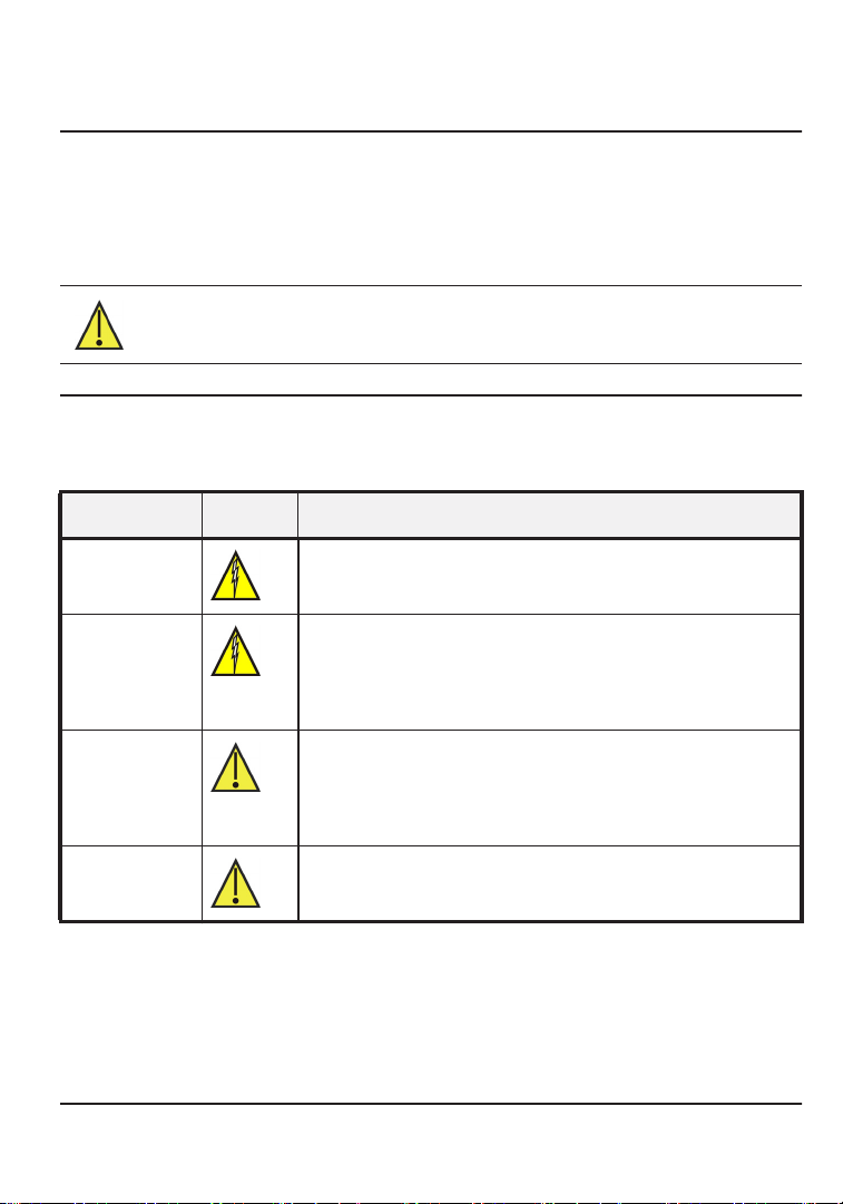
Alert Icon Description
Danger Imminently hazardous situation which, if not avoided,
will result in serious injury or death.
Warning Potentially hazardous situation which, if not avoided,
could result in serious injury or death.
Potential electrical shock hazard which, if not avoided,
could result in serious injury or death.
Caution Potentially hazardous situation which, if not avoided,
could result in physical injury or damage to the product
or environment. It may also be used to alert against
unsafe practices.
Important Additional information on how to use the product.
Table 1-1 - Icons
About this Manual Introduction • 1
Page 8
1.3. General Safety Requirements
IMPORTANT: Before using this product, carefully read and strictly follow the instructions
in the manual. Ensure that all product documentation is retained and available to anyone
operating the instrument.
DANGER! This instrument is neither certified nor approved for operation in
oxygen-enriched atmospheres. Failure to comply may result in personal injury or death.
DANGER! This instrument has not been designed to be intrinsically safe for use in areas
classified as being hazardous locations. For your safety, DO NOT use it in hazardous
(classified) locations.
WARNING! Use this product only for the purposes specified in this document and under
the conditions listed.
CAUTION! In the event of an alarm or over-range condition, the sensor must be
re-calibrated to ensure continued accuracy.
CAUTION! This product must be re-calibrated if installed in a non-room condition
environment (For example, temperature or humidity extremes).
CAUTION! The gas diffusion path can become occluded (moisture, dust, debris, frozen
condensation) over time resulting in reduced or complete lack of gas detection and
alarming function. Routine visual inspection of the gas detector and bump testing are
suggested to ensure proper gas detection and alarm function.
CAUTION! Except for maintenance detailed in this manual, these products should only be
opened and/or serviced by authorized Emerson Technical Support personnel.
Failure to comply may void the warranty.
CAUTION! Operator assumes responsibility for complying with all laws, rules and
regulations governing the use of this product.
2 • MRLDS-450 Refrigerant Gas Detection I&O Manual 026-1316 Rev 2
Page 9
CAUTION! Use only genuine Emerson parts and accessories. Failure to comply may
impair the operation of the product and/or void the warranty.
CAUTION! Only operate the product within the framework of a risk-based alarm signaling
concepts.
WARNING! The gas diffusion path can become occluded (moisture, dust, debris, frozen
condensation) over time, resulting in reduced or complete lack of gas detection and
alarming function. Routine visual inspection of the gas detector and bump testing are
recommended to ensure proper gas detection and alarm function. For information on
calibrating the sensor, refer to the “Care and Maintenance” section of this manual.
1.4. Safe Connection of Electrical Devices
WARNING! Before connecting this instrument to electrical devices not mentioned in this
manual, consult the manufacturer or a qualified professional. Failure to comply may result
in personal injury and/or damage to the product.
Safe Connection of Electrical Devices Introduction • 3
Page 10
2 Product Description
2.1. Intended Uses/Applications
MRLDS-450 Gas Detection Series instruments continuously monitor ambient air
(indoor or outdoor) for the following gas types:
• Refrigerants
• Oxygen
• Toxic and combustible gases
The MRLDS-450 refrigerant gas detector is designed for use in refrigeration
applications and with the integrated audio-visual alarm indication, can be operated
as a stand-alone unit (with additional local alarm signaling as required), or it may be
connected to a facility's building management system (BMS). It enables compliance
with refrigerant safety codes (ASHRAE 15 and EN378) and alarms to alert
personnel in the event of a refrigerant leak.
DANGER! This instrument is neither certified nor approved for operation in
oxygen-enriched atmospheres. Failure to comply may result in EXPLOSION.
DANGER! This instrument has not been designed to be intrinsically safe for use in areas
classified as being hazardous locations. For your safety, DO NOT use it in hazardous
(classified) locations.
2.2. MRLDS-450
2.2.1. MRLDS-450 Product Overview
The Emerson MRLDS-450 continuously monitors indoor or outdoor ambient air for
the following gases:
• Refrigerants
• Oxygen
• Toxic and combustible gases
4 • MRLDS-450 Refrigerant Gas Detection I&O Manual 026-1316 Rev 2
Page 11
With the integrated Modbus communication, analog output and relays, the
instrument can be operated as a stand-alone unit or as a third-party device capable
of accepting digital and/or analog outputs from the gas detectors, such as a Building
Management System (BMS) or a Supervisory Controller. The instrument is
designed to be installed in non-classified, non-hazardous, permanent locations.
Figure 2-1 - MRLDS-450
2.2.2. MRLDS-450 Design Features
• Transmitter: IP66 rated ABS enclosure
• Power options:
• 24VAC
• 19.5 to 28.5VDC
• Diagnostic/Status LED (3 color): Green, Orange, and Red
• Configurable output signal options
• 3× Relays (high alarm/low alarm/fault)
• 1× Analog Output (4 to 20mA, 0 to 5V, 0 to 10V, 1 to 5V, 2 to 10V)
• Digital Output (Modbus RTU signal)
Bluetooth communication allows for full instrument configuration, initiation of
calibration, bump test and functional test mode, and viewing of status information
via the corresponding MRLDS-450 iOS/Android app.
Non-intrusive magnetic wand can be used to initiate calibration of the device.
MRLDS-450 Product Description • 5
Page 12
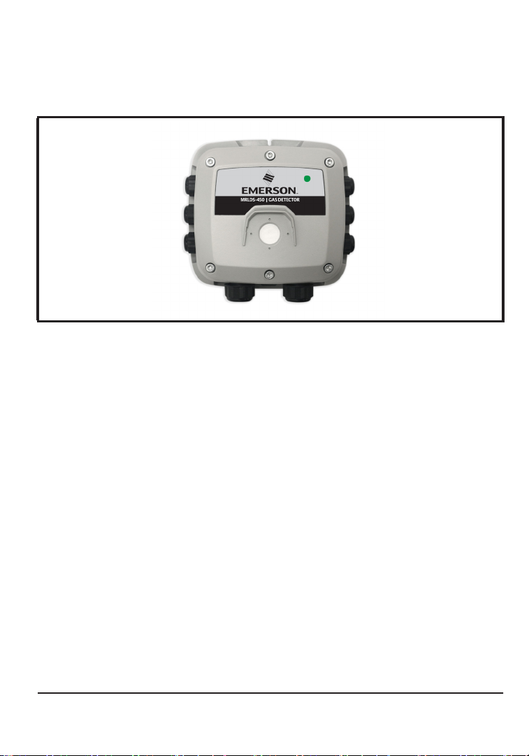
2.2.3. MRLDS-450 Component Overview
Figure 2-2 - MRLDS-450 Component Locations
# Component Description
1 M16 Cable Glands (x6)
2 Rubber Gasket
3 Internal Alarm Buzzer
4 Power Connections (x2)
5 Digital Connection (Modbus)
6 Analog Connection
7 Tactile Switch #1
8 Ribbon Cable Connection (To Sensor)
9 Tactile Switch #2
10 Relay 3 Connection (FAULT)
11 Relay 2 Connection (HIGH)
12 Relay 1 Connection (LOW)
13 Magnetic (Mag) Switch #1
14 Magnetic (Mag) Switch #2
15 M20 Cable Glands (x2)
Table 2-1 - MRLDS-450 Component Descriptions
6 • MRLDS-450 Refrigerant Gas Detection I&O Manual 026-1316 Rev 2
Page 13

3 Installation
CAUTION! The manufacturer of this product requires that a bump test or calibration be
performed following installation to verify instrument functionality.
3.1. General Information
Every detail of installation site selection is critical to ensure overall system
performance and effectiveness. Strict compliance and considerable thought must be
given to every detail of the installation process, including, but not limited to the
following:
• Regulations as well as local, state, and national codes that govern the installation of
gas monitoring equipment.
• Electrical codes that govern the routing and connection of electrical
cables to gas monitoring equipment.
• The full range of environmental conditions to which the instruments
• The physical characteristics of the gas or vapor to be detected.
• The specifics of the application (For example, possible leaks, air movement/draft,
etc.)
• The degree of accessibility required for maintenance purposes.
• The types of optional equipment and accessories that will be used with the system.
• Any limiting factors or regulations that would affect system performance or
installations.
• Wiring details, including:
• The MRLDS-450 enclosure provides the following cable gland openings:
• 2×, M20, supports 10-14mm cable outer diameter
• 6×, M16, supports 4-8mm cable outer diameter
• Secondary circuit must be supplied from an isolating source.
• The wiring for the relays must be selected and fused according to the rated
voltages, currents, and environmental conditions.
• If stranded conductions are used, ferrule should be used.
• To comply with RFI immunity regulations, it is necessary to ground the shield of
the communications cable at the PLC, GDA controller, front-end controller or
Building Management System (For example, the chassis, the ground bus-bar,
etc.).
power and signal
will be exposed.
General Information Installation • 7
Page 14
3.2. Restrictions
The installation location must have appropriate supply power available for the
instrument (For example, 19.5 to 28.5VDC or 24VAC). This ultimately determines
the distance the instrument can be mounted from the controller or power supply.
3.3. Mechanical Installation
WARNING! DO NOT allow the lid/sensor to hang from the ribbon cable. Failure to
comply may result in damage to the product.
1. Using the provided hardware, securely mount the MRLDS-450 Gas Detector
according to the product dimensions, maximum wiring lengths and following
considerations:
a. Environment: the full range of environmental conditions when selecting a
location.
b. Application: the specifics of the application (possible leaks,
etc.) when selecting a location.
c. Accessibility: the degree of accessibility required for maintenance purposes
when selecting a location.
d. Target Gas: the specific gravity of the target gas when selecting
instrument.
2. Using a 5/32” (4mm) hex key/allen wrench (not included) remove the lid and
disconnect the ribbon cable from the base.
3. Set the lid and rubber gasket aside to be reinstalled later.
air movement/draft,
the height of the
3.4. Electrical Installation
3.4.1. Preparations
IMPORTANT: If analog output is configured for 4 to 20mA output, ensure that the current
loop is connected to a sinking current loop monitor before powering on the instrument.
Otherwise, a fault may be displayed indicating an open loop condition. If analog output is
unused, ensure it is configured as a voltage output (1-5V) to prevent an open loop fault
condition. The analog output is designed as sourcing.
WARNING! Ensure wiring for relays and connections for sensor(s) are made before
applying power.
8 • MRLDS-450 Refrigerant Gas Detection I&O Manual 026-1316 Rev 2
Page 15
CAUTION! This product uses semiconductors which can be damaged by electrostatic
discharge (ESD). When handling the printed circuit boards (PCBs), observe proper ESD
precautions so that the electronics are not damaged.
3.4.2. Power and Signal Wiring
The product comes with cable glands and plugs pre-installed. The power entry cable
gland is without a gland plug. Use the appropriate cable glands to insert and connect
the wires for power and signal to the appropriate terminals as indicated in the figure
and wiring table that follow. The PCB terminal blocks are a pluggable type and may
be removed to aid termination.
IMPORTANT:
• For 24VAC installations sharing a transformer in a daisy-chain configuration, neutral
polarity must be maintained for all instruments.
• 24VAC power polarity must not be reversed.
• For a more robust system, a dedicated transformer for each MRLDS is recommended to
prevent damage caused by wiring errors.
• Fasten terminal screws.
Power Description Label Wiring Termination
24VDC/VAC IN
Power
Digital Output
Analog
Output
Table 3-1 - Power and Signal Wiring
24VDC/VAC OUT
(power daisy chain
terminal)
MODBUS Network
Communications
Voltage or Current
Output
24V IN: - 24VDC/VAC neutral/ground
24V IN: + 24VAC neutral
24V OUT: - 24VDC/VAC neutral/ground
24V OUT: + 24VAC neutral
MODBUS: B RS-485 “B” (inverted)
MODBUS: A RS-485 “A” (non-inverted)
MODBUS: GND RS-485 GND
MODBUS: SH RS-485 Shield
ANALOG: - Analog output ground
ANALOG: + Analog output signal (+)
3.4.3. Relay Wiring
WARNING! Relays are rated for 0 to 30V AC/DC. DO NOT apply main power onto these
relays.
Electrical Installation Installation • 9
Page 16
Using appropriate cable glands, connect the wires for relay 1, relay 2, and relay 3 to
the terminals as indicated in Table 3-2.
Relay Function
1 Low Alarm
2 High Alarm
3 Fault Alarm
Table 3-2 - Relay Wiring Configuration
When configured according to the factory default settings, the relays are
de-energized during normal operation (not fail-safe). Fail-safe mode can be
configured. When configured for Failsafe operation, relays are energized during
normal operation. Failsafe operation ensures relays are triggered in cases of power
failure at the instrument. In Failsafe operation, normally open and normally closed
terminals are reversed as indicated in Table 3-3
Terminal Normal Operation Failsafe Operation
NC Normally Closed Normally Open
COM Common Common
NO Normally Open Normally Closed
Table 3-3 - Relay Wiring Terminal Configuration
3.4.4. Modbus RTU RS-485 Interface
For the Modbus RS-485 network use a 16 to 24 AWG (0.5 to 1mm2) 3-core,
2 twisted pair + ground, shielded cable with 120Ω characteristic impedance.
IMPORTANT: Recommended: Belden 3105A (or equivalent).
The Modbus address, baud rate, stop bit, parity and slave termination is configured
through the setup menu. No jumpers or hardware switch settings are required.
Ensure that the communication parameters within the network, including the BMS,
are configured identically.
To ensure optimal performance of the Modbus network ensure the following
guidelines are implemented:
• Ensure instruments are configured in a single bus topology, connecting multiple buses in
parallel or branching multiple units from the main bus, may introduce impedance mismatches,
reflections and/or signal distortions.
• Avoid long stubs when connecting instruments to the bus, stubs should be less than one (1)
meter in length.
10 • MRLDS-450 Refrigerant Gas Detection I&O Manual 026-1316 Rev 2
Page 17
• Ensure A/B signal polarity is maintained throughout RS-485 network.
• Connect cable shield drain to physical earth or ground at the controller only.
• Ensure cable shield integrity is maintained throughout RS-485 network.
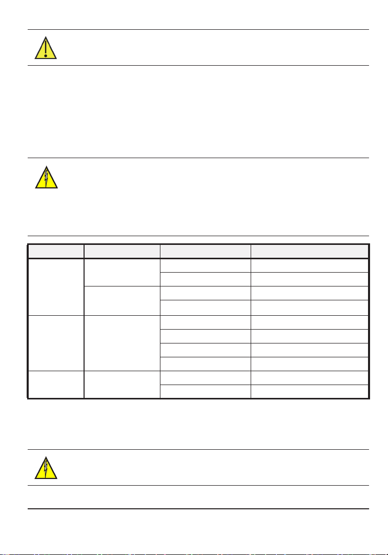
For Modbus end-of-line termination, use 150Ω ohm resistor or termination block
P/N 537-2711. Do not use MRLDS 120Ω ohm on-board termination with Site
Supervisor or E2.
Site Supervisor Setup - Device and COMM
Figure 3-1 - Site Supervisor Network Setup
Electrical Installation Installation • 11
Page 18
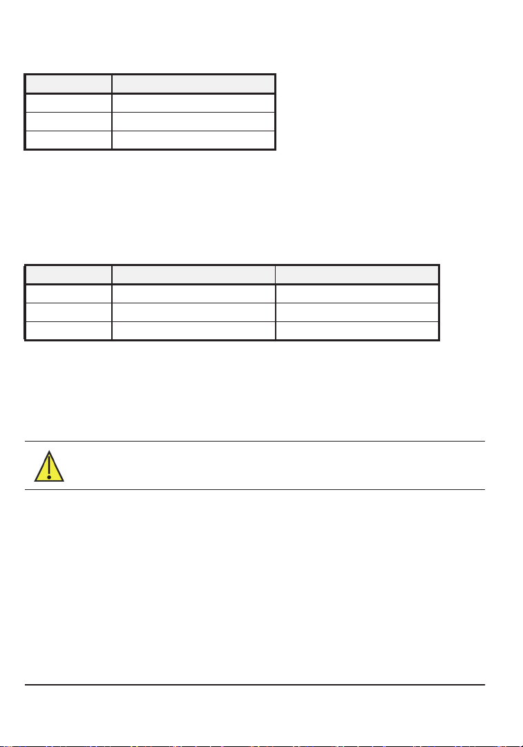
E2 Setup - Device and COMM
Figure 3-2 - E2 Network Setup
3.4.5. Conclusion
After all wiring is completed, power the transmitter and confirm operation, and then
prepare to seal the enclosure.
Align the enclosure gasket (primary transmitter and remote sensor if equipped),
replace the lid, and tighten the six (6) screws. Tightening torque should be limited to
tightening by hand, and should be uniform in pattern.
12 • MRLDS-450 Refrigerant Gas Detection I&O Manual 026-1316 Rev 2
Page 19

3.5. Set Up MRLDS-450 Application in E2
Note: Installing the MRLDS-450 requires version E2E 4.10F01 or later. You must
add a description file for version E2 3.10F01 or less.
3.5.1. New Installation: Uploading the MRLDS-450 Description File to E2
The MRLDS-450 requires adding a description file (P/N 527-0754) and license key
to E2 version 3.0X or later. Contact Customer Service to obtain this information:
Email: Solutions.CustomerService@Emerson.com
Phone: 770-425-2724 Option 4
Note: UltraSite32 software should be installed to perform a
description file upload.
Connect to E2 using UltraSite32
1. Launch UltraSite program and login.
2. View the Directory Level and then Site Level.
3. Right-click Site Level and click Connect.
4. Locate the E2 where the MRLDS_450.dsc will be installed.
5. Right-click the unit and select Upload Description File.
6. Click Browse to select the appropriate description file (5270754.dsc) file for
MRLDS-450 from the computer and click Open.
7. Click Upload. A window will display the description file was successfully
imported. Click OK. The description file should appear inside the window.
8. Once completed, disconnect from the E2 and reboot the E2 controller.
Note: Do not omit the step of rebooting the controller.
Device Setup
E2 Serial Port Setup
1. Log into the E2 controller.
2. Press I, , , and (General Controller Information), then
press B twice to move to the C3: Serial tab.
Set Up MRLDS-450 Application in E2 Installation • 13
Page 20

3. Press the down arrow key to the COM Connection where the device is
wired.
4. Press D (LOOK UP) and select MODBUS-1, MODBUS-2 or
MODBUS-3, then press > to set configuration.
5. Press D to select options and set the MODBUS connection as follows:
COM Baud: 19200 Baud
COM Data Size: 8
COM Parity Even
COM Stop Bits: 1
6. Press >to set configuration, then J to save changes.
7. Press H to return to the Home screen.
Adding the MRLDS-450 Application in E2
1. Press Ithen , , and to enter Connected I/O Boards and
Controllers.
14 • MRLDS-450 Refrigerant Gas Detection I&O Manual 026-1316 Rev 2
Page 21

2. Press B to move to the C3: ECT tab. Highlight the MRLDS-450
application and enter the desired number of devices under Quantity up to a
maximum of 15.
Figure 3-3- ECT Tab
3. Press J to save the changes.
4. Press H to return to the Home screen.
Commissioning the MRLDS-450
1. Press Ithen , , and to enter the Network
Summary screen.
Set Up MRLDS-450 Application in E2 Installation • 15
Page 22

2. Highlight the MRLDS-450 to be commissioned and press D
Figure 3-4- Network Summary Screen
3. If a box with Select Network appears on the screen, select the MODBUS
number where you configured the device – either MODBUS-1,
MODBUS-2, or MODBUS-3 and press >
Figure 3-5- Select MODBUS output
16 • MRLDS-450 Refrigerant Gas Detection I&O Manual 026-1316 Rev 2
Page 23

4. Select the address for the device and press >
Figure 3-6- Select Device Address
Note: The MODBUS address must be the same as the address assigned on the
device.
Set Up MRLDS-450 Application in E2 Installation • 17
Page 24

5. A window will appear. Press > to continue.
Figure 3-7- Set Physical Address for the MRLDS-450
6. Press J to save the assigned address.
7. Press H to return to the Home screen and press I then , ,
and to enter the Network Summary screen again.
18 • MRLDS-450 Refrigerant Gas Detection I&O Manual 026-1316 Rev 2
Page 25

8. After a few seconds, the MRLDS-450 should appear Online.
Figure 3-8- MRLDS-450 Network Summary Screen Online Status
Set Up MRLDS-450 Application in E2 Installation • 19
Page 26

Viewing the Status
1. Press I then , , and (this is equivalent to pressing
I, , ) or use the cursor to navigate to MRLDS-450
and press >
Figure 3-9- Configured Applications
20 • MRLDS-450 Refrigerant Gas Detection I&O Manual 026-1316 Rev 2
Page 27

2. View the status of the detector on the MRLDS-450 Summary screen and
press E to go to Setup.
Figure 3-10-MRLDS-450 Status Screen
Set Up MRLDS-450 Application in E2 Installation • 21
Page 28

4 Operation
4.1. Overview of Normal Operation
CAUTION! Before leaving the instrument for normal operation, check the configuration
for proper settings and check calibration.
4.1.1. Applying Power and the Start-up Sequence
After applying power, the instrument will go through a start-up sequence
(initialization, audible/visual test and self-test sequence). After the start-up sequence
completes, the instrument will enter a warm-up period to allow the sensor element
to stabilize before reporting a valid output.
Step Description
1 Switch power on.
Observe start-up sequence and warm-up phase:
• Green LED will blink at 0.5 Hz for about five (5) minutes
2
3
Table 4-1 - Instrument Start-up Sequence
• Modbus flag for warm-up is set
• Buzzer is off
• Relay state is “no alarm”
• Gas reading invalid
Observe normal operation:
• Green LED is steady on
• Modbus flag for warm-up is cleared
• Buzzer is off
• Relay state is “no alarm”
• Gas reading valid
4.1.2. Verifying Analog Signals
The MRLDS-450 gas detector features a single configurable analog output. During
normal operation, the analog output of the instrument is proportional to the detected
gas concentration and can be selected from the following:
• 1 to 5V (default)
• 0 to 5V
22 • MRLDS-450 Refrigerant Gas Detection I&O Manual 026-1316 Rev 2
Page 29

• 2 to 10V
• 0 to 10V
• 4 to 20mA
The MRLDS-450 Gas Detector uses different voltage/current values to indicate
various modes of operation. In normal operation the relative gas concentration
output is indicated by the analog output level. Output level is proportional to the gas
level as shown in Table 4-2:
Gas Concentration 1-5V 0-5V 2-10V 0-10V 4-20mA
0% 1V 0V 2V 0V 4mA
50% 3V 2.5V 6V 5V 12mA
100% 5V 5V 10V 10V 20mA
Table 4-2 - Gas Concentration Levels
The instrument may also enter several special states, these are indicated by the
specific analog output levels indicated in Table 4-3:
Mode of Operation 1-5V 0-5V 2-10V 0-10V 4-20mA
Instrument Fault ≤ 0.3V N/A ≤ 0.6V N/A ≤ 1.2mA
Offline Mode/Maintenance 0.75V N/A 1.5V N/A 3mA
Drift below zero 0.95V N/A 1.9V N/A 3.8mA
Normal operation 1-5V 0-5V 2-10V 0-10V 4-20mA
Measuring range exceeded 5.12V 5.12V 10.25V 10.25V 20.5mA
Fault on analog interface > 5.25V > 5.25V > 10.5V > 10.5V > 21mA
Table 4-3 - Analog Output Levels
4.1.3. Verifying the Modbus Signal
The MRLDS-450 Gas Detector provides a Modbus RTU digital interface. All status
messages and most parameters that can be accessed and/or configured through the
Bluetooth® interface can also be accessed and/or configured via RS485 for Modbus
RTU.
4.1.4. Status Indication
The MRLDS-450 gas detections provide external indication of its current
operational state via audible and visual feedback. Visual indication of the instrument
status is provided by a single tri-color LED (Green/Red/Orange). MRLDS-450 gas
detection instruments also provide relays outputs. Instrument states and
corresponding outputs are shown in Table 4-4.
Overview of Normal Operation Operation • 23
Page 30

State LED Buzzer
Warm-up OFF OFF OFF
Relay 1
(LOW)
Relay 2
(HIGH)
Relay 3
(Fault)
Normal
Low Alarm ON OFF OFF
High Alarm
Offline
Fault
Negative Gas Fault
Zero Cal. Fault OFF OFF OFF
Span Cal. Fault OFF OFF OFF
Table 4-4 - Status Indicators
OFF OFF OFF
ON ON OFF
OFF OFF OFF
OFF OFF ON
OFF OFF ON
4.1.5. Switch Functions
User interaction with the MRLDS-450 gas detector is accomplished through the use
of two magnetic switches located on the bottom of each unit. To actuate a magnetic
switch, apply the supplied magnetic wand to the relevant switch location as shown
in Figure 4-1.
24 • MRLDS-450 Refrigerant Gas Detection I&O Manual 026-1316 Rev 2
Page 31

Figure 4-1 - Magnetic Switches
Switch locations above are referred to in this document as MAG#1 and MAG#2.
Depending on the duration the switch is held, a short “tap” or long “hold” will be
detected.
• To carry out a tap function, tap the relevant switch location for one (1) second, until a
single “chirp” is heard and remove the wand to confirm a “tap.”
• To carry out a hold function, do not remove the magnetic wand after
but continue to hold for more than five (5) seconds, until a double “chirp” is heard,
and remove wand to confirm a “hold.” If either switch is held for more than 30
seconds, a stuck switch fault will be indicated.
• To interact with the instrument without use of the magnetic wand, two internal push
button tactile switches may be used. Remove the lid without removing the ribbon
cable to access. Internal switches T
MAG#1 and MAG#2.
ACT#1 and TACT#2 mirror the functions of
the first “chirp”
The function of each switch depends on the current state of the instrument. Refer to
Table 4-5 for switch functions in each instrument state.
Overview of Normal Operation Operation • 25
Page 32

State Switch 1 Tap Switch 1 Hold Switch 2 Tap Switch 2 Hold
Warm-up Enable
Normal
Low Alarm Mute Buzzer Ack. Latched Alarm
High Alarm Mute Buzzer Ack. Latched Alarm
Offline
Fault Mute Buzzer Ack. Latched Fault
Negative Gas
Fault
Zero Cal. Fault
Span Cal. Fault Acknowledge Fault
Table 4-5 - Switch Functions
Bluetooth®
Connectivity
Start Zero
Calibration
Mute Buzzer Start Zero Calibration
Acknowledge
Fault
Disable
Bluetooth®
Connectivity
Start Span Calibration
4.1.6. Reset System to Factory Default Settings
To reset system to factory defaults, remove lid and hold TACT#1 and TACT#2
simultaneously for 30 seconds. Instrument will restart to confirm factory reset.
Alternatively, see Section 4.2.3.4., Reset to Factory Defaults, for instructions on
resetting instrument configuration via the MRLDS-400 Series App.
4.2. MRLDS-400 Series Application
Download the MRLDS-400 Series App.
The companion smartphone application allows users to perform a variety of
functions to configure and interact with the MRLDS-450 gas detector, including:
• View real-time measurements
• Configure instrument
• Test outputs
• Calibrate/Bump test instrument
• Generate customizable calibration certificates
4.2.1. Enable Bluetooth® Connection
1. Enable Bluetooth® discovery by tapping MAG#1 for 1-second. (After 10 seconds, the
device will indicate that it is discoverable with audible heartbeat until it has been
paired, discovery has timed-out, or has been canceled.)
26 • MRLDS-450 Refrigerant Gas Detection I&O Manual 026-1316 Rev 2
Page 33

2. Launch the MRLDS-400 Series App and select the Bluetooth® icon at the bottom of
the screen to initiate a scan.
3. Select MRLDS-450 default alias is “18TMAE” from the list of available
gas detectors.
4. When prompted, enter the passkey (default is “123456”).
IMPORTANT: Default alias, passkey, and unlock code can be changed via the
MRLDS-400 Series App’s configuration menu. Default values should be changed after
instrument installation for security purposes.
4.2.2. Checking Status
Current Instrument status can be viewed from the Home tab. The Home tab displays
the following status information:
Figure 4-2 - MRLDS-400 Series App Home Tab
No. Description
1 Alias, user-configured instrument name.
2 Serial, instrument 8-digit serial number.
3 Gas, gas type currently detected by instrument.
4 Status ring, provides visual indication of various instrument states (expanded on Table 4-7)
5 Live measurement, current measurement in given measurement units.
6 Measurement unit, displayed measurement unit (PPM/PPB/%LEL/%VOL)
Table 4-6 - MRLDS-400 Series App Home Tab Features
MRLDS-400 Series Application Operation • 27
Page 34

State Status Ring Description
Warm-up Green Gas detector stabilizing after power on or restart.
Normal Green Normal Operation.
Low Alarm Yellow Gas measurement has exceeded low alarm setpoint.
High Alarm Red Gas measurement has exceeded high alarm setpoint.
Offline Orange Gas Detector in maintenance mode and is not actively monitoring gas.
Fault Orange A fault has been detected.
Negative Gas
Fault
Zero Cal.
Fault
Span Cal.
Fault
Table 4-7 - Status Ring of Various Instrument States
Orange
Orange
Orange
Gas Detector calibration has drifted below zero, requires zero
calibration.
Error occurred during zero calibration. Zero calibration has not be
updated. Zero calibration required.
Error occurred during span calibration. Span calibration has not be
updated. Span calibration required.
4.2.3. Instrument Configuration
For security, access to configuration and calibration options are restricted to
authorized users only. Access to these functions require use of an unlock code.
To unlock instrument configuration, go to the Configure tab to set up the device.
When prompted, enter unlock code to access device configuration. (The
instrument’s default code is “1234”). Instrument will remain unlocked until
Bluetooth® connection has ended.
IMPORTANT: Default alias, passkey, and unlock code can be changed via the
MRLDS-400 Series App’s configuration menu. Default values should be changed after
instrument installation for security purposes.
4.2.3.1. Change Alias
To allow easy identification of a given instrument, an alias can be assigned to each
instrument. This alias is displayed when searching for an instrument via Bluetooth®,
on Calibration Cert and in the Home tab. To set the alias:
• On the Configure tab select Alias. Enter the required alias for instrument and select
OK.
• The instrument must be restarted for change to take effect. Selecting the Home tab
then Restart will reboot device.
• Reconnect to instrument to confirm the alias has been updated.
28 • MRLDS-450 Refrigerant Gas Detection I&O Manual 026-1316 Rev 2
Page 35

4.2.3.2. Change Unlock Code
To prevent unauthorized access to instrument configuration and calibration, the
default instrument unlock code should be changed during commissioning. To
change unlock code:
• On the Configure tab select Modbus Unlock Code. Enter the new 4-digit unlock
code for instrument and select OK.
• The instrument must be restarted for changes to take effect. Selecting the Home tab,
then Restart will reboot the device.
• Reconnect to instrument to confirm the unlock code has been updated.
IMPORTANT: If the custom unlock code is forgotten, the unlock code may be reset to
default value (1234) by resetting system to factory defaults. Refer to Section 4.1.6., Reset
System to Factory Default Settings for the system reset procedure. Note that a system reset
will return all custom system configurations to defaults.
4.2.3.3. Change Bluetooth® Passcode
To prevent unauthorized access to instrument status, the default instrument
Bluetooth® passcode code should be changed during commissioning. To change
Bluetooth® passcode:
• On the Configure tab select Bluetooth Passcode. Enter new 6-digit passcode for the
instrument and select OK.
• The instrument must be restarted for changes to take effect. Selecting the Home tab,
then Restart will reboot the device.
• Reconnect to instrument to confirm the Bluetooth
IMPORTANT: If the custom passcode is forgotten, the unlock code may be reset to default
value (123456) by resetting system to factory defaults. Refer to Section 4.1.6., Reset System
to Factory Default Settings for system reset procedure. Note that a system reset will return
all custom system configurations to defaults.
® Passcode has been updated.
MRLDS-400 Series Application Operation • 29
Page 36

4.2.3.4. Reset to Factory Defaults
Instrument configuration may be reset to factory defaults via the smartphone
application:
• On the Configure tab select Reset to Factory Default and select OK to confirm.
• The instrument will automatically restart and disconnect from the smartphone
application.
WARNING! Resetting system to factory defaults will remove all custom system
configuration including unlock code and Bluetooth passcode. After system reset custom
unlock and Bluetooth passcodes should be configured to prevent unauthorized access and
reconfiguration of instrument.
4.2.3.5. Alarm Configuration
Low Alarm Setpoint
The value above which a low alarm condition occurs. The low alarm setpoint must
be less than the high alarm setpoint and greater than the low alarm limit. The low
alarm limit is the fixed minimum limit that is sensor–specific and not editable.
Range of acceptable setpoints is displayed when updating the parameter. To update
the setpoint:
• On the Configure tab select Alarm then Low Alarm Setpoint. Enter the new
setpoint and select OK to confirm.
IMPORTANT: In instruments with an oxygen sensor installed, low alarm behavior
operates in a depletion mode where gas measurements BELOW the low alarm setpoint
initiate a low alarm. This allows monitoring of oxygen displacement and enrichment
scenarios.
IMPORTANT: To prevent intermittent alarm operation at the setpoint due to measurement
noise this instrument implements hysteresis at the setpoint. Once the alarm level is
exceeded, the gas measurement must return a fixed percentage below the alarm threshold
before the alarm is disabled. Typical hysteresis value is set at 5% of full scale; however,
this is sensor-specific and non-editable.
High Alarm Setpoint
The value above which a high alarm condition occurs. The high alarm setpoint must
be less than the sensor full scale range and greater than the low alarm setpoint.
Range of acceptable setpoints is displayed when updating the parameter. To update
setpoint:
• On the Configure tab select Alarm then High Alarm Setpoint. Enter the new
setpoint and select OK to confirm.
30 • MRLDS-450 Refrigerant Gas Detection I&O Manual 026-1316 Rev 2
Page 37

IMPORTANT: To prevent intermittent alarm operation at the setpoint due to measurement
noise, this instrument implements hysteresis at the setpoint. Once the alarm level is
exceeded, the gas measurement must return a fixed percentage below the alarm threshold
before the alarm is disabled. Typical hysteresis value is set at 5% of full scale; however,
this is sensor-specific and non-editable.
Alarm Latching
Enabling alarm latching will maintain alarm or fault condition even after the alarm
or fault condition is no longer active. When latched, the alarm or fault condition
must be manually acknowledged before the condition will be cleared. This allows
transient alarm or fault conditions to be identified.
If an alarm is latched, for example, the condition has occurred but is no longer active,
an acknowledgment button will appear on the Home screen. Select this button to
acknowledge the latched condition and clear the alarm or fault.
When disabled, the alarm or fault status clears automatically as soon as the condition
is no longer active. To configure:
• On the Configure tab select Alarm then Alarm Latching. Select Enable/Disable
and OK to confirm.
4.2.3.6. Modbus Configuration
Address
Sets instrument address for connection to RS-485 Modbus interface. (Default: 1).
To set address:
• On the Configure tab select Modus, then Address. Select 1-247 and OK to confirm.
IMPORTANT: Ensure all instruments on RS-485 bus have been configured with unique
node addresses. If two instruments have been configured with same address, bus contention
will occur preventing communications with these instruments via the RS-485 interface.
Baud Rate
Sets instrument baud rate for connection to RS-485 Modbus interface baud).
To set baud rate:
• On the Configure tab select Modus then Baud Rate. Select 9600/19200 (default)
and OK to confirm.
MRLDS-400 Series Application Operation • 31
Page 38

Stop Bits
Sets instrument stop bits for connection to RS-485 Modbus interface (Default: 1 stop
bits). To set number of stop bits:
• On the Configure tab select Modus then select Stop Bits. Select 1 or 2 and OK to
confirm.
Parity
Sets instrument parity for connection to RS-485 Modbus interface (None, Odd, or
Even (default).
To set parity:
• On the Configure tab select Modus then select Parity. Select None/Odd/Even and
OK to confirm.
IMPORTANT: Stop bits must be set to 1 where parity is Odd or Even.
Enable 120Ω Termination
For optimal communication reliability, in RS-485 Modbus networks the last
instrument physically connected to the RS-485 bus must include a 120Ω termination
resistor. This is to reduce the potential for electrical signal reflection on long buses
due to impedance mismatches. Typically, this requires a physical resistor with the
same characteristic impedance of the bus cable to be installed on the bus.
MRLDS-450 instruments include this termination resistor on all instruments and
allow this termination to be enabled via this configuration setting without the need
for an external physical resistor. To enable this termination resistor:
• On the Configure tab select Modbus then select Enable 120Ω Termination.
Select Enable/Disable and select OK to confirm.
IMPORTANT: Termination resistor should only be enabled on last instrument physically
connected to RS-485 bus. An external resistor should not be connected where this is enabled
on the instrument.
4.2.3.7. Output Configuration
Analog Output Range
Sets instrument analog output range. Available ranges: 1-5V (default), 0-5V,
0-10V, 2-10V, 4-20mA. To set range:
• On the Configure tab select Outputs, then select Analog Output Range. Select
desired range and select OK to confirm.
32 • MRLDS-450 Refrigerant Gas Detection I&O Manual 026-1316 Rev 2
Page 39

Buzzer
Enable or disable buzzer. Buzzer provides local audible alarm/fault indication.
Buzzer is enabled by default. To enable/disable buzzer:
• On the Configure tab select Outputs, then Buzzer. Select Enable/Disable and select
OK to confirm.
Relay Failsafe
Enable or disable Relay Failsafe operation. When configured for fail-safe operation,
relays are energized during normal operation. Failsafe operation ensures relays are
triggered in cases of power failure at the instrument. In Failsafe operation, normally
open and normally closed terminals are reversed as indicated in Section 3.4.3., Relay
Wiring. Relays are configured as non-Failsafe by default. To enable/disable relay
Failsafe:
• On the Configure tab select Outputs then Relay Failsafe. Select Enable/Disable
and OK to confirm.
Alarm Delay
Sets delay in minutes before instrument will indicate an alarm condition after low or
high alarm threshold has been exceeded. May be used to prevent short transient
alarm conditions from activating alarms. Alarm delays may be set for 0-15 minutes.
Alarm delay is configured as 0 minutes by default. To set alarm delay:
• On the Configure tab select Outputs then Alarm Delay. Enter the desired delay in
minutes (0-15) and OK to confirm.
Analog Zero Adjust
Analog zero adjust applies a fixed offset to the analog output. This allows removal
of small errors in the output between the gas detection instrument and the
measurement at the controller due to cable resistance when using voltage outputs.
To apply adjustment ensure instrument is outputting fixed voltage (default 1V at
zero ppm or use output test function to set specific voltage value), monitor remote
measurement and adjust zero offset until remote measurement matches expected
voltage output. Adjustment is limited to ±10% full scale. To set analog zero
adjustment:
• On the Configure tab select Outputs then Analog Zero Adjust. Use the slider to set
desired offset adjustment.
• Alternatively, select “Analog Zero Adjust (X.X%)” text and enter specific offset
required (-10 to 10).
MRLDS-400 Series Application Operation • 33
Page 40

Analog Span Range
Analog span range scales the FSD (full-scale deflection) of the analog output. The
selected range determines the equivalent gas measurement at the analog output
maximum range.
Example: R134A 1000ppm, 0-5V analog output. If Analog Span Range is set to
20%, the full analog output range only covers the first 20% of the gas measurement
range, for example, 0-200ppm will output 0-5V, above 200ppm the output will be
truncated to 5V. Note that sensor resolution stays at the value for the max range.
To set analog span range:
• On the Configure tab select Outputs then Analog Span Range. Use the slider to set
desired range.
• Alternatively, select “Analog Span Range (X.X%)” text and enter specific offset
required.
34 • MRLDS-450 Refrigerant Gas Detection I&O Manual 026-1316 Rev 2
Page 41

5 Care and Maintenance
5.1. Maintenance Intervals
Interval Function
Check calibration
During Commissioning
Every 6-12 Months**
As Required Replace sensor module(s)
Table 5-1 - Maintenance Intervals and Functions
* These can be activated via Modbus commands or via MRLDS-400 Series App.
** Typical maintenance frequency can vary by sensor type.
Sensor Type Recommended Maintenance Interval Typical Sensor Lifetime
Electrochemical* 12 months 2-3 years
Catalytic Bead
Semiconductor*
Infrared 12 months 5-7 years
Table 5-2 - Maintenance Intervals and Functions
* Sensors should be checked after exposure to significant concentrations of gas, which can
shorten the sensor lifetime and/or reduce its sensitivity.
Check LEDs for proper operation*
Check for proper buzzer and relay operation*
Check signal transmission to the BMS.BAS (central controller) if connected*
Inspection by trained service personnel.
Check LEDs for proper operation*
Check for proper buzzer and relay operation*
Check signal transmission to the BMS/BAS (central controller) if connected*
Calibrate the sensor or contact Emerson Technical Support for sensor exchange
with factory - calibrated sensor
Zero calibration -1-3 months
Span calibration - 6 months
6 months after commissioning
12 months thereafter
5-7 years
4-6 years
Maintenance Intervals Care and Maintenance • 35
Page 42

5.2. Adjustments
5.2.1. Introduction
Adjustment of the detector must be performed at regular intervals as required by
national standards or regulations (For example, EN 378, ASHRAE 15, BREEAM,
etc.).
Breathing Hazard: Calibration gas MUST NOT be inhaled! See appropriate
Safety Data Sheets. Calibration gas should be vented into a fume hood or to
the outside of the building.
Zero First, Then Span: For proper operation, never adjust the span before
completing a zero adjustment. Performing these operations out of order will
cause faulty calibration.
IMPORTANT: Emerson recommends calibrating detectors within the application-specific
condition and with target gas. This method of zeroing the detector in the application
environment and performing a target gas calibration is more accurate. A surrogate gas
calibration may only be performed as an alternative if a target gas calibration is
not possible.
IMPORTANT: The sensor should be fully stabilized (at least 2 hours, preferably 24 hours).
IMPORTANT: When entering the functions for zero or span adjustment, the detector will
automatically enter OFFLINE mode, and will remain OFFLINE until either the
OFFLINE mode is canceled by tapping the respective magnetic switch, or the OFFLINE
mode times out within 6 minutes (typical) after the adjustment has ended.
5.2.2. General Calibration Procedure
IMPORTANT: The MRLDS-450 Gas Detector MAY NOT be in an alarm or fault condition
during calibration. Acknowledge any alarms or faults BEFORE attempting to begin the
calibration process.
IMPORTANT: Except for CO2 or O2 sensors, calibration gas must be in a balance of air,
not nitrogen (N
36 • MRLDS-450 Refrigerant Gas Detection I&O Manual 026-1316 Rev 2
).
2
Page 43

IMPORTANT: Calibration and/or bump testing requires the MRLDS-450 Calibration
Adapter Kit (P/N 809-1190).
IMPORTANT: At elevations higher than 6,560’ (ft) (3,000 m), calibration will result in a
lower reading. Above 6,560’ (ft), the instrument should be calibrated in the environment of
operation.
1. Fit calibration adapter to the gas detector lid.
Figure 5-1 - Calibration Adapter Fitting
2. If using a variable flow regulator, adjust the gas flow to approximately 0.3 L/min.
5.2.3. Zero Adjustment
Ambient air can be used to zero the sensor instead of synthetic air only if the area is
known to be free of the target gas or any gas to which the sensor may be
cross-sensitive. In this case, no cylinder or calibration adapter is needed for the zero
adjustment.
IMPORTANT: The MRLDS-450 MAY NOT be in an alarm or fault condition during
calibration. Acknowledge any alarms or faults BEFORE attempting to begin the
calibration process.
IMPORTANT: Except for CO2 or O2 sensors, ambient air may be used instead of zero gas
if the area is known to be free of the target gas or any gases to which the sensor may be
cross-sensitive.
Adjustments Care and Maintenance • 37
Page 44

1. Begin zero adjustment:
a. MRLDS-400 App: On the Home tab select Calibrate then scan the barcode on gas cylinder
or manually enter values for zero gas.
b. Manual: Hold MAG#1 for more than five (5) seconds. The LED will blink GREEN-GREEN-
RED when the instrument is ready.
2. Apply zero gas (or ambient air per warning above).
3. Confirm the start of calibration:
a. MRLDS-400 App: Press the Start Zero button.
b. Manual: Tap MAG#1 within 30 seconds or the instrument will time-out and return to normal
operation.
4. Complete zero adjustment:
a. MRLDS-400 App: App will countdown to completion. If calibration is successful, proceed to
Step 5. If calibration is unsuccessful, return to the Home screen and press the Acknowledge
button to clear the zero calibration fault.
b. Manual: The LED will blink GREEN-RED, GREEN-RED-RED, GREEN-RED-RED-RED,
etc. until calibration is complete. To abort, hold MAG#1 for >5-seconds, turn off gas flow and
remove the calibration adapter. If calibration is successful (green LED), proceed to Step 5. If
calibration is unsuccessful (LED blinks orange @ 2 Hz), tap MAG#1 to discard the calibration
attempt.
5. Turn off gas flow from zero gas.
6. Replace zero gas with calibration gas in preparation for span adjustment.
5.2.4. Span Adjustment
IMPORTANT: Except for CO2 or O2 sensors, calibration gas must be in a balance of air,
not nitrogen (N2).
IMPORTANT: At elevations higher than 6,560’ (ft) (2,000 m), calibration will result in a
lower reading. Above 6,560’ (ft) the instrument should be calibrated in the environment of
operation.
1. Begin span adjustment:
a. MRLDS-400 App: Scan barcode on gas cylinder or manually enter values for zero gas.
b. Manual: Hold MAG#2 for more than five (5) seconds. The LED will blink GREEN-GREEN-
ORANGE when the instrument is ready.
2. Apply calibration gas at the concentration listed on the calibration gas concentration
label (located on top of the instrument).
• Part Number
• Serial Number
• Sensor Type
• Maximum Range
3. Confirm the start of calibration:
38 • MRLDS-450 Refrigerant Gas Detection I&O Manual 026-1316 Rev 2
Page 45

a. MRLDS-400 App: Press the Start Span button.
b. Manual: Tap MAG#2 within 30 seconds or the instrument will time-out and return to normal
operation.
4. Complete zero adjustment:
a. MRLDS-400 App: App will countdown to completion. If calibration is successful, proceed to
Step 5. If calibration is unsuccessful, return to the Home screen and press the Acknowledge
button to clear the zero calibration fault.
b. Manual: The LED will blink GREEN-ORANGE, GREEN-ORANGE-ORANGE, GREEN-
ORANGE-ORANGE-ORANGE, etc. until calibration is complete. To abort, hold MAG#2 for
>5-seconds, turn off gas flow and remove the calibration adapter. If calibration is successful
(LED blinks green-orange-red), proceed to Step 5. If calibration is unsuccessful (LED blinks
orange @ 2 Hz), tap MAG#2 to discard the calibration attempt.
5. Turn off gas flow from calibration gas and remove the calibration adapter.
6. Allow sensor to recover/stabilize before the instrument returns to normal operation
(green LED).
5.2.5. System Bump Test
A bump test is a live test of the system to verify that the detector responds to gas and
all connected alarm devices, BMS, etc. are operating accordingly. It is
recommended that all involved persons are informed about the test and certain
alarms might have to be inhibited (For example, shutdown valves, notification of
authorities, etc.).
IMPORTANT: The manufacturer of this product requires that a bump test or calibration
be performed following installation to verify instrument functionality.
1. Connect adapter and gas cylinder according to the instructions in the General
Calibration Procedure.
2. If desired, disable/silence external annunciators (For example, shutdown valves,
notification of authorities, etc.):
a. MRLDS-400 App: On the Home tab select Calibrate then Bump. Toggle TAKE OFFLINE
to disable communications to external devices.
b. Manual: Inform building personnel of test so that external devices can be disabled/silenced.
3. Apply a sufficiently high concentration of the target gas to trigger alarms, but NOT
pure refrigerant or hydrocarbons (For example, do not use a butane lighter).
4. Once thresholds have been exceeded, relays should activate, digital outputs should
transmit the gas concentration and:
a. MRLDS-400 App: Gas concentration should be displayed, the instrument status should be
LOW ALARM or HIGH ALARM and alarms states should be ON.
b. Manual: LED status should display LOW ALARM or HIGH ALARM.
5. Turn off gas flow and remove the calibration adapter.
Adjustments Care and Maintenance • 39
Page 46

6. Allow sensor to recover/stabilize before the instrument returns to normal operation
(green LED).
5.3. Troubleshooting
5.3.1. Hexadecimal Format
All fault codes can be retrieved through the Modbus interface and are shown in
hexadecimal (hex) format. A hex digit can represent multiple codes as shown below:
Hex
Code
0 0 6 1+2+3 D 1+4+8
1 1 7 1+2+4 E 2+4+8
2 2 8 8 F 1+2+4+8
3 1+2 9 1+8
4 4 A 2+8
5 1+4 B 1+2+8
Table 5-3 - Hexadecimal Code Format
Equivalent
Error
Code(s)
Hex
Code
Equivalent
Error
Code(s)
Hex
Code
Equivalent
Error
Code(s)
5.3.2. Fault Codes
IMPORTANT: If a sensor fault occurs during a gas alarm condition, then the fault
overrides the alarm condition.
Sensor faults may be decoded using the following table. Note that several faults may
be reported at the same time. For example, fault code “00000003” is a combination
of fault codes 00000001 (No sensor signal) and 00000002 (Voltage out of
specification 1V).
IMPORTANT: If a “last fault” attribute indicates that a fault has occurred at some point
in time, but the corresponding “current fault” attribute shows no fault, then the problem
has self-healed and no service action is required.
40 • MRLDS-450 Refrigerant Gas Detection I&O Manual 026-1316 Rev 2
Page 47

Fault Bit System Fault Possible Cause Required Action(s)
0x00000001 Software fault
0x00000002
0x00000004
0x00000008
0x00000010
0x00000020
0x00000040
0x00000080
0x00000100
0x00000200
0x00000400
Voltage out of
specification 1V
Voltage out of
specification 3.3V
Voltage out of
specification 5V
Voltage out of
specification 5.4V
Voltage out of
specification 12V
Voltage out of
specification VIN
System Flash Memory
Read Fault
System Flash Memory
Write Fault
System Flash Memory
CRC fault
System Invalid
Configuration
0x00000800 GPIO fault
0x00001000 Modbus Fault
0x00002000
Analog Output Fault
(MRLDS-450 Only)
0x00004000 Bluetooth Fault
0x00008000 Stuck switch
0x00010000 Sensor Element Out
0x00020000 Sensor Element Fault
Firmware error (e.g.
unexpected state)
Voltage rail out of range
Voltage rail out of range
Voltage rail out of range
Voltage rail out of range
Voltage rail out of range
Voltage rail out of range
Error reading from
internal Flash
Error writing to internal
Flash
Error in internal Flash
CRC
Error in system
configuration
Error detected on GPIO
pin
Error detected in Modbus
Communications
Error updating DAC value
Error detected in
Bluetooth module
Magnetic and/or Tactile
switch activated for > 1
minute
Cannot detect sensor
element
Fault detected in sensor
element
Power-cycle. If it re-occurs,
call product support
Call product support
Power-cycle. If it re-occurs,
call product support
Call product support
Power-cycle. If it re-occurs,
call product support
Call product support
Check sensor connection
Replace sensor nodule
Table 5-4 - Sensor Fault Codes
Troubleshooting Care and Maintenance • 41
Page 48

Fault Bit System Fault Possible Cause Required Action(s)
0x00040000
0x00080000
0x00100000
0x00200000
0x00400000
0x00800000
0x01000000
0x02000000
0x04000000
Sensor ADC Sensor Read
Fault
Sensor ADC Current Read
Fault
Sensor AFE Read Fault
(EC only)
Sensor AFE Write Fault
(EC only)
Sensor AFE Status Fault
(EC only)
Sensor EEPROM Read
Fault
Sensor EEPROM Write
Fault
Sensor EEPROM CRC
Fault
Sensor EEPROM
Configuration Fault
0x08000000 Sensor UART Read Fault
0x10000000 Sensor Temperature Fault
0x20000000
Negative Gas
Concentration Fault
0x40000000 Zero Calibration failure Zero calibration failed
0x80000000 Span Calibration failure Span calibration failed
Cannot read from sensor
ADC
Cannot read from current
ADC
Cannot read from EC
sensor AFE
Cannot write to EC sensor
AFE
Error in EC sensor AFE
Error in reading from
sensor EEPROM
Error in writing to sensor
EEPROM
Error in CRC from sensor
EEPROM
Error in sensor EEPROM
data
Cannot read from sensor
UART
Temperature cannot be
read or is out of
specification
Sensor output has drifted
too negative
Check sensor connection/
Replace Sensor Module
Power-cycle / check sensor
connection / replace sensor
module
Call product support
Power-cycle / replace sensor
module
Replace sensor module
Check sensor connection /
replace sensor module
Ensure sensor is operating
within specified temperature
range / check sensor
connections
Initiate zero calibration (Via
App / Hold MAG#2)
Acknowledge failed
calibration (Via App / Hold
MAG#1)
Acknowledge failed
calibration (Via App / Hold
MAG#2)
Table 5-4 - Sensor Fault Codes
42 • MRLDS-450 Refrigerant Gas Detection I&O Manual 026-1316 Rev 2
Page 49

5.4. Sensor Maintenance
CAUTION! This product uses semiconductors that can be damaged by electrostatic
discharge (ESD). When handling the PCB, care must be taken so that the electronics are
not damaged.
Figure 5-2 - MRLDS-450 Components
Figure 5-3 - IP66 Sensor Configuration
Sensor Maintenance Care and Maintenance • 43
Page 50

IP66 Product arrangement shown for reference; Remote Daughterboard PCB shown
(used for Remote IP66 Sensor Configurations). Note: Cable Glands and labeling are
factory installed.
5.4.1. Replacing Sensor Module
CAUTION! This product uses semiconductors that can be damaged by electrostatic
discharge (ESD). When handling the PCB, care must be taken so that electronics are not
damaged.
To replace the gas detector’s sensor module:
1. Power-down the gas detector.
2. Using a 5/32” (4mm) hex key/allen wrench (not included), remove the lid and
disconnect the ribbon cable from the sensor module.
3. Remove installed sensor module from the lid by holding onto the housing and turning
counter
-clockwise 90°. Take care not to apply excessive force to the sensor module’s
circuit board. When the square tab of the sensor housing is aligned with the lock icon,
firmly pull the module to remove it from the housing.
4. Install the new sensor module by aligning the square tab with the lock icon before
firmly pressing it into the enclosure.
sensor module’s circuit board, rotate the sensor module clockwise 90° (or until the
triangle icon aligns with the lock icon on the lid).
5. Connect the ribbon cable (to the sensor module and transmitter) and close the lid.
6. Ensure gasket is aligned correctly and tighten the lid using
“X” pattern. Tightening torque should be limited to hand tight and should be uniform.
Taking care not to apply excessive force to the
the supplied hardware in an
44 • MRLDS-450 Refrigerant Gas Detection I&O Manual 026-1316 Rev 2
Page 51

Figure 5-4 - Tightening Pattern
7. Power-up the gas detector.
8. After the start-up sequence has finished, check sensor response (bump test).
5.5. Cleaning the Instrument
Clean the detector with a soft cloth using water and a mild detergent. Rinse with
water. Do not use any alcohols, cleaning agents, sprays, polishes, detergents, etc.
Page 52

6 Additional Information
6.1. Sensor Principle
6.1.1. Electrochemical Sensors
Electrochemical sensors measure the partial pressure of gases under atmospheric
conditions. The monitored ambient air diffuses through a membrane into the liquid
electrolyte in the sensor. The electrolyte contains a measuring electrode, a
counter-electrode, and a reference electrode. An electronic “potentiostat” circuit
ensures a constant electrical voltage between measuring electrode and reference
electrode. Voltage, electrolyte, and electrode material are selected to suit the gas
being monitored so that it is transformed electrochemically on the measuring
electrode and a current flows through the sensor. This current is proportional
to the gas concentration. At the same time, oxygen from the ambient air reacts at
the counter electrode electrochemically. The current flowing through the sensor is
amplified electronically, digitized and corrected for several parameters (For
example, the ambient temperature).
6.1.2. Catalytic Bead Sensors
A catalytic bead sensor measures the partial pressure of combustible gases and
vapors in ambient air. It uses the heat-of-combustion principle.
The monitored air diffuses through the sintered metal disc into the sensor. The
mixture of combustible gases, vapors, and air are catalytically combusted at a heated
detector element (called a pellistor). The oxygen content in the air must be greater
than 12 Vol%. Due to the resulting heat-of-combustion, the temperature of the
detector element rises. This increase in temperature causes a change of resistance in
the detector element, which is proportional to the concentration of the mixture of
combustible gases and vapors in the monitored air. In addition to the catalytically
active detector element, there is a compensator element. Both elements are parts of
a Wheatstone bridge. Thus environmental effects like changes in ambient
temperature or humidity are almost entirely compensated.
IMPORTANT: Certain substances in the atmosphere to be monitored may
impair the sensitivity of the sensors. Such substances include, but are not limited to:
1. Polymerizing substances such as acrylonitrile, butadiene, and styrene.
2. Corrosive compounds such as halogenated hydrocarbons (releasing halogens such as
bromine, chlorine or fluorine when oxidized) and halogen hydride acids as well as acidic gaseous
compounds such as sulfur dioxide and nitrogen oxides, Catalyst poisons such as sulfurous and
phosphorous compounds, silicon compounds (especially silicones), and metal-organic vapors.
46 • MRLDS-450 Refrigerant Gas Detection I&O Manual 026-1316 Rev 2
Page 53

It may be necessary to check the calibration if the sensor has been exposed for a long
time to a high concentration of flammable gases, vapors, or the above-mentioned
contaminating substances.
The nature of catalytic bead sensor technology means that sensor drift may typically
be up to ±5% LEL per month. Instruments using these sensors should be zeroed
regularly following the instructions in Section 5, Care and Maintenance.
6.1.3. Semiconductor Sensors
Semiconductor or metallic oxide sensors (MOSs) are among the most versatile of all
broad-range sensors. They can be used to detect a variety of gases and vapors in low
ppm or even combustible ranges. The sensor is made up of a mixture of metallic
oxides. They are heated to a temperature between 302ºF and 572ºF (150ºC and
300ºC) depending on the gas(es) to be detected. The temperature of operation as well
as the “recipe” of mixed oxides determines the sensor selectivity to various toxic
gases, vapors, and refrigerants. Electrical conductivity greatly increases as soon as a
diffusion process allows the gas or vapor molecules to come in contact with the
sensor surface. Water vapor, high ambient humidity, temperature fluctuations, and
low oxygen levels can result in higher readings.
IMPORTANT: Certain substances in the environment to be monitored may impair the
sensitivity of the sensors:
1. Materials containing silicone or silicone rubber/putty.
2. Corrosive gases such as hydrogen sulfide, sulfur oxide, chlorine, hydrogen chloride, etc.
3. Alkaline metals, saltwater spray.
6.1.4. Infrared Sensors
The infrared (IR) gas sensor is designed to measure the concentration of combustible
gases and vapors in the ambient air. The sensor principle is based on the
concentration-dependent absorption of infrared radiation in measured gases.
The monitored ambient air diffuses through a sintered metal material into the
enclosure of an optical “bench.” The broadband light emitted by an IR source passes
through the gas in the optical bench and is reflected by the walls from where it is
directed towards a dual-element detector. One channel of the detector measures the
gas-dependent light transmission, while the other channel is used as a reference.
The ratio between measurement and reference signal is used to determine the gas
concentration. Internal electronics and software calculate the concentration and
produce an output signal.
Sensor Principle Additional Information • 47
Page 54

6.2. Disposing of the Instrument
6.2.1. Disposing of the Electrical and Electronic Equipment
EU-wide regulations governing the disposal of electrical and electronic appliances
which have been defined in the EU Directive 2012/19/EU and in national laws have
been effective since August 2012 and apply to this device.
Common household appliances can be disposed of using special collecting and
recycling facilities. However, this device has not been registered for household
usage. Therefore it must not be disposed of through these channels. The device can
be returned to Emerson for disposal. Please do not hesitate to contact Emerson
Technical Support if you have any further questions on this issue.
6.2.2. Disposing of Sensors
Dispose of sensors in accordance with local laws.
DANGER! Do not dispose of sensors in fire due to the risk of explosion and resulting
chemical burns.
WARNING! Do not force open electrochemical sensors.
IMPORTANT: Observe the applicable local waste disposal regulations. For information,
consult your local environmental agency, local government offices or appropriate waste
disposal companies.
48 • MRLDS-450 Refrigerant Gas Detection I&O Manual 026-1316 Rev 2
Page 55

6.3. Technical Specifications
6.3.1. General Specifications
Category Specifications
Analog Current
Signals to Central
Controller
Power Supply and
Relays
Wiring
Table 6-1 - General Specifications
Analog Voltage
Modbus RTU over RS-485
Operating voltage 19.5 to 28.5VDC; 24VAC ± 20%, 50/60 Hz
Inrush current 1.5 A
Operating power (max) MRLDS-450: 4W, 170mA @ 24VDC
Relay rating
Audible alarm Internal Buzzer ≥72 dB at 4” (10cm)
Alarm delay 0 to 15 minutes (selectable)
Power and analog signal
Modbus network
Cable gland
Normal operation: 4 to 20mA
Drift below zero: 3.8mA
Measuring range exceeded: 20.5mA
Instrument fault: ≤ 1.2mA
Fault on analog interface: > 21mA
Offline mode/Maintenance signal: 3mA steady signal
0 to 5V; 1 to 5V (default); 0 to 10V; 2 to 10V
(selectable)
During fault condition, 1 to 5V and 2 to 10V outputs
are 0V.
Baud rate: 9,600 or 19,200 (default) (selectable)
Start bits: 1
Data bits: 8
Parity: None, Odd, Even (default) (selectable)
Stop bits: 1 or 2 (selectable)
Retry time: 500 ms, min time between retries
End of message: Silent 3.5 characters
3 SPDT
1 A at 24VAC/VDC, resistive load
2-core shielded cable, 16 to 20 AWG (0.5 to 1.5mm2)
3-core, 2 twisted pair + ground, shielded cable with 120
Ω characteristic impedance, 16 to 24 AWG (0.5 to 1.5
2
)
mm
M20, 10-14mm cable outer diameter
M16, 4-8mm cable outer diameter
Technical Specifications Additional Information • 49
Page 56

Category Specifications
Enclosure protection IP66
Physical
Specifications
Environmental
Agency
Approvals
Table 6-1 - General Specifications
Enclosure Size (W×H×D)
(Approx.)
Weight (Approx.) MRLDS-450: 1lb, 1oz (480g)
Temperature - 40 to 120ºF (-40 to 50ºC)
Storage temperature - 5 to 100ºF (-20 to 40ºC)
Humidity
Pressure 23.6 to 32.5 inch Hg/800 to 1,100 mbar
Elevation 0 to 10,000 ft. (3,000 m) altitude
Influences
CE, EN 50270:2015, UL/CSA/IEC/EN 61010-1
MRLDS-450 IP66: 6.5×6.5×3.4” (165×165×87mm)
5 to 90% RH, non-condensing
(15 to 90% RH, non-condensing, EC sensors excl. O2)
For influences on the measurement performance and
restrictions
7 Ordering Information
of a particular sensor, see sensor data sheet.
Emerson
P/N
809-1040 CO2 0-5,000ppm 809-1140 CO2 0-5,000ppm IR
809-1041 CO2 0-10,000ppm 809-1141 CO2 0-10,000ppm IR
809-1047 R404A 0-1,000ppm 809-1147 R404A 0-1,000ppm SC
809-1048 R407A 0-1,000ppm 809-1148 R407A 0-1,000ppm SC
809-1049 R410A 0-1,000ppm 809-1149 R410A 0-1,000ppm SC
809-1050 R22 0-1,000ppm 809-1150 R22 0-1,000ppm SC
809-1056 R448A 0-1,000ppm 809-1156 R448A 0-1,000ppm SC
809-1058 R513A 0-1,000ppm 809-1158 R513A 0-1,000ppm SC
809-1066 R422D 0-1,000ppm 809-1166 R422D 0-1,000ppm SC
809-1068 R449A 0-1,000ppm 809-1168 R449A 0-1,000ppm SC
Table 7-1 - Part Numbers and Ordering Information
50 • MRLDS-450 Refrigerant Gas Detection I&O Manual 026-1316 Rev 2
IP66, 3 x Relays, Analog
Output, Modbus Output,
Audible & Visual Alarms
Gas Type and Detection
Range
Emerson
P/N
Replacement Sensor
Pre-calibrated Sensor
Modules
Sensor
Type
Page 57

Emerson P/N MRLDS-450 Accessories
809-1190 Calibration Adapter Kit
809-1191 Horn + strobe 24VDC; blue lens
809-1192 Horn + strobe 24VDC; amber lens
809-1193 Horn + strobe 24VDC; red lens
809-1194 Horn + strobe; blue lens; MP120K 120VAC adapter
809-1195 Horn + strobe; amber lens; MP120K 120VAC adapter
809-1196 Horn + strobe; red lens; MP120K 120VAC adapter
Table 7-2 - Accessory Part Numbers and Ordering Information
Technical Specifications Ordering Information • 51
Page 58

For Technical Support call 770-425-2724 or email ColdChain.TechnicalServices@Emerson.com
The contents of this publication are presented for informational purposes only and they are not to be construed as warranties or guarantees,
express
or implied, regarding the products or services described herein or their use or applicability. Emerson Retail Solutions, Inc. and/or its
affiliates (collectively “Emerson”), reserves the right to modify the designs or specifications of such products at any time without notice.
Emerson does not assume responsibility for the selection, use or maintenance of any product. Responsibility for proper selection, use and
maintenance of any product remains solely with the purchaser and end-user.
Emerson is a trademark of Emerson Electric Co. ©2020 Emerson Retail Solutions, Inc.
All rights reserved.
 Loading...