

Page 1
MRLDS-250
Quick Setup Guide
The Modular Refrigeration Leak Detection Sensor is
Emerson’s state-of-the-art infrared refrigerant gas
detector that can detect a wide range of gases. The
MRLDS-250 can be used on a stand-alone basis or
integrated into supervisory controls. The MRLDS-250
can be used in locations that require continuous
monitoring and to add gas detection solutions to an
existing system.
The MRLDS-250 is available in two versions:
• The broadband gas detector is used as a general
purpose gross leak detector and is factory tested and
certified to +/- 35% accuracy.
• The gas specific versions come factory certified and
calibrated with +/- 3% accuracy to the target refrigerant
when there is a need for more accurate detection.
MRLDS-250 Installation
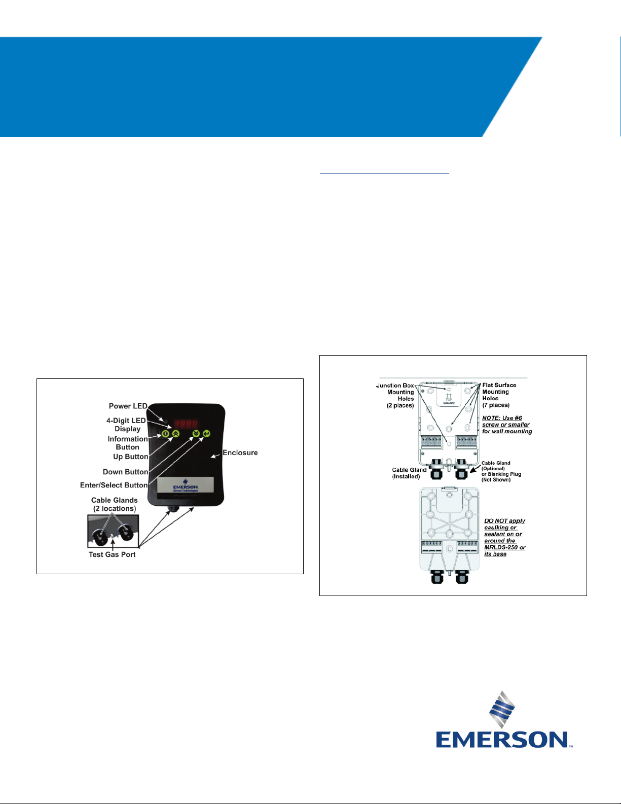
Mounting the MRLDS-250
1. To open the housing as received, use a flat blade
screwdriver and depress the top latch. While pushing
the latch, grasp the back edge of the housing near the
latch and pull the back away.
2. Position the base to the pre-determined mounting
location.
3. For Wall Mount, attach the MRLDS-250 base to the
mounting surface using two #6 screws (provided)
through two of the seven mounting holes
(see Figure 2). For Junction Box Mount, attach the
MRLDS-250 base to the junction box through the two
junction box holes.
Figure 1 - MRLDS-250 Components
For complete part number and installation information, see
the full MRLDS-250 manual (P/N 026-1315).
Document Part # 026-4413 Rev 2 Page 1 of 4
©2018 Emerson Climate Technologies Retail Solutions, Inc. This document may be photocopied for personal use.
Visit our website at http://www.emerson.com for the latest technical documentation and updates.
Figure 2 - Front and Back of the MRLDS-250 Base
Page 2
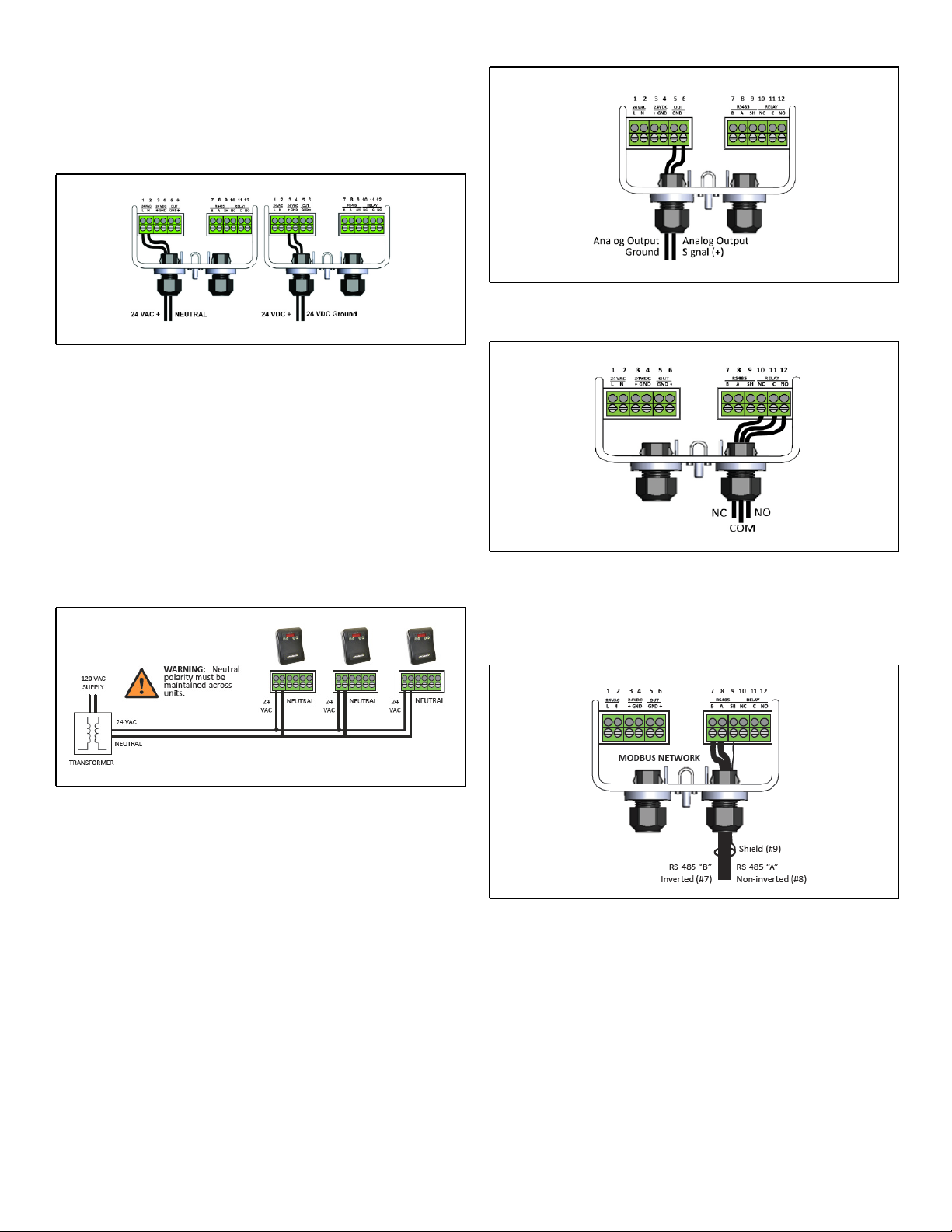
Wiring and Configuration
Either 24VAC or 24VDC may be used to power the
MRLDS-250. Connect wiring to the appropriate terminal
locations. Use two wires, between 14 and 22 AWG.
Refer to Figure 3 for AC wiring (left) or DC wiring (right):
Figure 3 - Supply and Power Wiring Options
WARNING: The MRLDS-250 must be powered by:
• A suitable UL 60950/CSA certified power supply
that is isolated from line voltage by double
insulation.
• An appropriately rated UL listed/CA Class 2
Transformer; a 10VA Transformer is
recommended.
Figure 5A - Analog Output Wiring
• For multiple devices cascaded, a 50VA Class 2
Transformer is recommended.
Figure 4 - Power Wiring of a Device Network
The MRLDS-250 provides an analog output signal that is
proportional to the level of gas detected. Connect two
18 to 20 AWG wires to terminal block positions 5 and 6
(see Figure 5A), noting ground and signal polarity.
Make relay connections (NO, NC, or both) using 18 to 20
AWG wires to terminal block positions 10, 11, and 12
(see Figure 5B), noting normally open, normally closed,
and common connectors.
Figure 5B - Sample Relay Output Wiring
NOTE: For MODBUS network communications wiring,
use only 18-24 AWG shielded twisted pair wire with 120
ohm characteristic impedance.
Figure 6 - MODBUS Network Communication Wiring
Document Part # 026-4413 Rev 2 Page 2 of 4
©2018 Emerson Climate Technologies Retail Solutions, Inc. This document may be photocopied for personal use.
Visit our website at http://www.emerson.com for the latest technical documentation and updates.
Page 3

NOTE: Be sure to enable the termination resister on the
device at each end of the network (see Figure 7):
Figure 7 - Termination Resister Setting
Set Up Analog Output Type and Scaling
1. For Analog Output, look for P.-03 on the parameter list
then press the Enter button.
2. Set the desired output by pressing Up or Down
3. Set the desired address by pressing Up or Down
and press the Enter button to save.
4. For the Baud Rate, look for the P.-13 parameter then
press the Enter button.
5. Select 00 for 9600 Baud or 01 for 19200 Baud. Press
the Enter button to save.
How to Add an MRLDS-250 to the E2 Controller
1. MRLDS-250 is only native on E2 Enhanced Controllers
with firmware version 4.08F03; otherwise you need to
add a description file and license key.
2. Contact Customer Service to obtain a license key:
a. Phone Number: 770-425-2724 Option 4
b. Email: Solutions.CustomerService@Emerson.com
3. Add the description file using UltraSite.
4. Reboot the controller after the upload.
5. Load the license key on the E2 by logging in and then
press , ,.
to select the type designated as follows:
• 00 Selects 0-5V
• 01 Selects 1-5V (Default)
• 02 Selects 0-10V
• 03 Selects 2-10V
• 04 Selects 4-20mA
3. Press the Enter button to save.
4. For Scaling, look for P.-16 on the parameter list then
press the Enter button.
5. This will allow you to select the full scale PPM value that
represents the maximum analog output (for example:
1000PPM = 5V when 1-5V output range was selected
for P.-03). Use Up or Down to adjust the value
and set it to 1000PPM.
6. Press the Enter button to save the setting.
MRLDS-250 Modbus Setup
Setting Up Modbus Address and Baud Rate
1. Press and hold the information button for five
seconds to activate the parameter list.
2. For the Address, look for P.-10 on the parameter list
6. Press F1 for ADD FEATURE and enter the License Key.
7. Add the MRLDS-250 by pressing , ,, to
access Connected I/O Boards and Controllers.
8. Press F2 twice to select C4: Third Party tab.
9. Scroll down to MGS250 and enter the quantity of
MRLDS-250 devices up to the maximum indicated.
10. Press the button to save.
11. Press , ,, for Network Summary or
+.
12. Scroll down to the MGS250 and press F4 for
COMMISSION.
13. Select the address the MRLDS-250 is set to and press
to confirm.
14. The MRLDS-250 should be Online on the E2 Network
Summary (press +).
How to Configure Alarm Setup on the E2
Controller
1. Press , and then select MGS250.
2. Press F5 for SETUP and F2 to select C2: Set Points.
3. Set the parameters depending on the System
Requirement and press the button to save.
then press the Enter button.
Document Part # 026-4413 Rev 2 Page 3 of 4
©2018 Emerson Climate Technologies Retail Solutions, Inc. This document may be photocopied for personal use.
Visit our website at http://www.emerson.com for the latest technical documentation and updates.
Page 4

MRLDS to MultiFlex I/O
How to Set a MultiFlex Input Point
1. An input point on a MultiFlex board consists of two terminals. One of these terminals labeled as SIG reads the signal from
the sensor, while the other, labeled 0v is where the sensor ground wire is connected:
Figure 8 - MultiFlex Input Point
2. The Analog Output Signal (+) should go to (SIG) terminal of the MultiFlex board and the Ground (GND) should go to (0v)
terminal of the board.
3. The DIP switch setting of the MultiFlex board terminal for the MRLDS-250 should be in the OFF position
(see Figure 9) because it supplies its own voltage signal to the point:
Figure 9 - MultiFlex Input Dip Switches
How to Set the Input Type on the E2 Controller
1. Press , , to go to the Input Status Screen.
2. Select the input point where the MRLDS-250 is connected, and press F1 for SETUP. Press for Analog.
3. Highlight Sensor Type and press F4 for LOOK UP. Select Linear and press to confirm.
4. Navigate down to Eng Units and press F4 for LOOK UP. Select PPM 33 and press to confirm.
5. Set the Low End Point and HighEnd Point equivalent to the range set on P-.03 for Analog Output.
6. Set the Low End EU and the High End EU equivalent to PPM Scaling set on P.-16.
7. For the Low End Limit, set it to -10% of Low End EU and for the HighEnd Limit, set it to +10% of
High End EU.
8. Press the button to save.
Document Part # 026-4413 Rev 2 Page 4 of 4
Visit our website at http://www.emerson.com for the latest technical documentation and updates.
Join Emerson Retail Solutions Technical Support on Facebook. http://on.fb.me/WUQRnt
For Technical Support call 770-425-2724 or email SolutionsTechSup@Emerson.com
The contents of this publication are presented for informational purposes only and they are not to be construed as warranties or guarantees, express or implied, regarding the products or services described
herein or their use or applicability. Emerson Climate Technologies Retail Solutions, Inc. and/or its affiliates (collectively “Emerson”), reserves the right to modify the designs or specifications of such products
at any time without notice. Emerson does not assume responsibility for the selection, use or maintenance of any product. Responsibility for proper selection, use and maintenance of any product remains
This document may be photocopied for personal use.
solely with the purchaser and end-user.
 Loading...