

Emerson Micro Motion H Series, Micro Motion H300, Micro Motion H025, Micro Motion H050, Micro Motion H100 Installation Manual
...
Installation Manual
20002346, Rev BC
Micro Motion® H-Series Hygienic Coriolis
Flow and Density Sensors
January 2019

Safety and approval information
This Micro Motion product complies with all applicable European directives when properly installed in accordance with the
instructions in this manual. Refer to the EU declaration of conformity for directives that apply to this product. The EU declaration
of conformity, with all applicable European directives, and the complete ATEX Installation Drawings and Instructions are available
on the internet at www.emerson.com or through your local Micro Motion support center.
Information affixed to equipment that complies with the Pressure Equipment Directive, can be found on the internet at
www.emerson.com.
For hazardous installations in Europe, refer to standard EN 60079-14 if national standards do not apply.
Other information
Full product specifications can be found in the product data sheet. Troubleshooting information can be found in the configuration
manual. Product data sheets and manuals are available from the Micro Motion web site at www.emerson.com.
Return policy
Follow Micro Motion procedures when returning equipment. These procedures ensure legal compliance with government
transportation agencies and help provide a safe working environment for Micro Motion employees. Micro Motion will not accept
your returned equipment if you fail to follow Micro Motion procedures.
Return procedures and forms are available on our web support site at www.emerson.com, or by phoning the Micro Motion
Customer Service department.
Emerson Flow customer service
Email:
• Worldwide: flow.support@emerson.com
• Asia-Pacific: APflow.support@emerson.com
Telephone:
North and South America
United States 800-522-6277 U.K. 0870 240 1978 Australia 800 158 727
Canada +1 303-527-5200 The Netherlands +31 (0) 704 136
Mexico +41 (0) 41 7686
111
Argentina +54 11 4837 7000 Germany 0800 182 5347 Pakistan 888 550 2682
Brazil +55 15 3413 8000 Italy 8008 77334 China +86 21 2892 9000
Europe and Middle East Asia Pacific
666
France 0800 917 901 India 800 440 1468
Central & Eastern +41 (0) 41 7686
111
Russia/CIS +7 495 981 9811 South Korea +82 2 3438 4600
Egypt 0800 000 0015 Singapore +65 6 777 8211
Oman 800 70101 Thailand 001 800 441 6426
Qatar 431 0044 Malaysia 800 814 008
Kuwait 663 299 01
South Africa 800 991 390
Saudi Arabia 800 844 9564
UAE 800 0444 0684
New Zealand 099 128 804
Japan +81 3 5769 6803
2

Installation Manual Contents
20002346 January 2019
Contents
Chapter 1 Planning........................................................................................................................ 5
1.1 Installation checklist.........................................................................................................................5
1.2 Best practices................................................................................................................................... 6
1.3 Temperature limits...........................................................................................................................6
1.4 Recommendations for hygienic and self-draining applications......................................................... 7
Chapter 2 Mounting.......................................................................................................................9
2.1 Mount the sensor............................................................................................................................. 9
2.2 Attach extended electronics...........................................................................................................10
Chapter 3 Transmitter power and I/O wiring................................................................................ 13
3.1 Options for wiring...........................................................................................................................13
3.2 Connect 4-wire cable......................................................................................................................13
3.3 Connect the 9-wire cable ............................................................................................................... 17
Chapter 4 Grounding....................................................................................................................19
Chapter 5 Supplementary information.........................................................................................21
5.1 Purge the sensor case .................................................................................................................... 21
Installation Manual 3

Contents Installation Manual
January 2019 20002346
4 Micro Motion H-Series
Installation Manual Planning
20002346 January 2019
1 Planning
1.1 Installation checklist
□ Make sure that the hazardous area specified on the approval tag is suitable for the
environment in which the meter will be installed.
□ Verify that the local ambient and process temperatures are within the limits of the
meter.
□ If your sensor has an integral transmitter, no wiring is required between the sensor and
transmitter. Follow the wiring instructions in the transmitter installation manual for
signal and power wiring.
□ If your transmitter has remote-mounted electronics, follow the instructions in this
manual for wiring between the sensor and the transmitter, and then follow the
instructions in the transmitter installation manual for power and signal wiring.
Table 1-1: Maximum cable lengths
Cable type To transmitter Maximum length
Micro Motion 4-wire All 4-wire MVD transmitters — 1,000 ft (305 m) without
Ex-approval
— 500 ft (152 m) with IIC
rated sensors
— 1,000 ft (305 m) with IIB
rated sensors
Table 1-2: Maximum lengths for user-supplied 4-wire cable
Wire function Wire size Maximum length
Power (VDC) 22 AWG (0.326 mm²) 300 ft (91 m)
20 AWG (0.518 mm²) 500NaN ft (NaN m)
18 AWG (0.823 mm²) 1,000 ft (305 m)
Signal (RS-485) 22 AWG (0.326 mm²) or larger 1,000 ft (305 m)
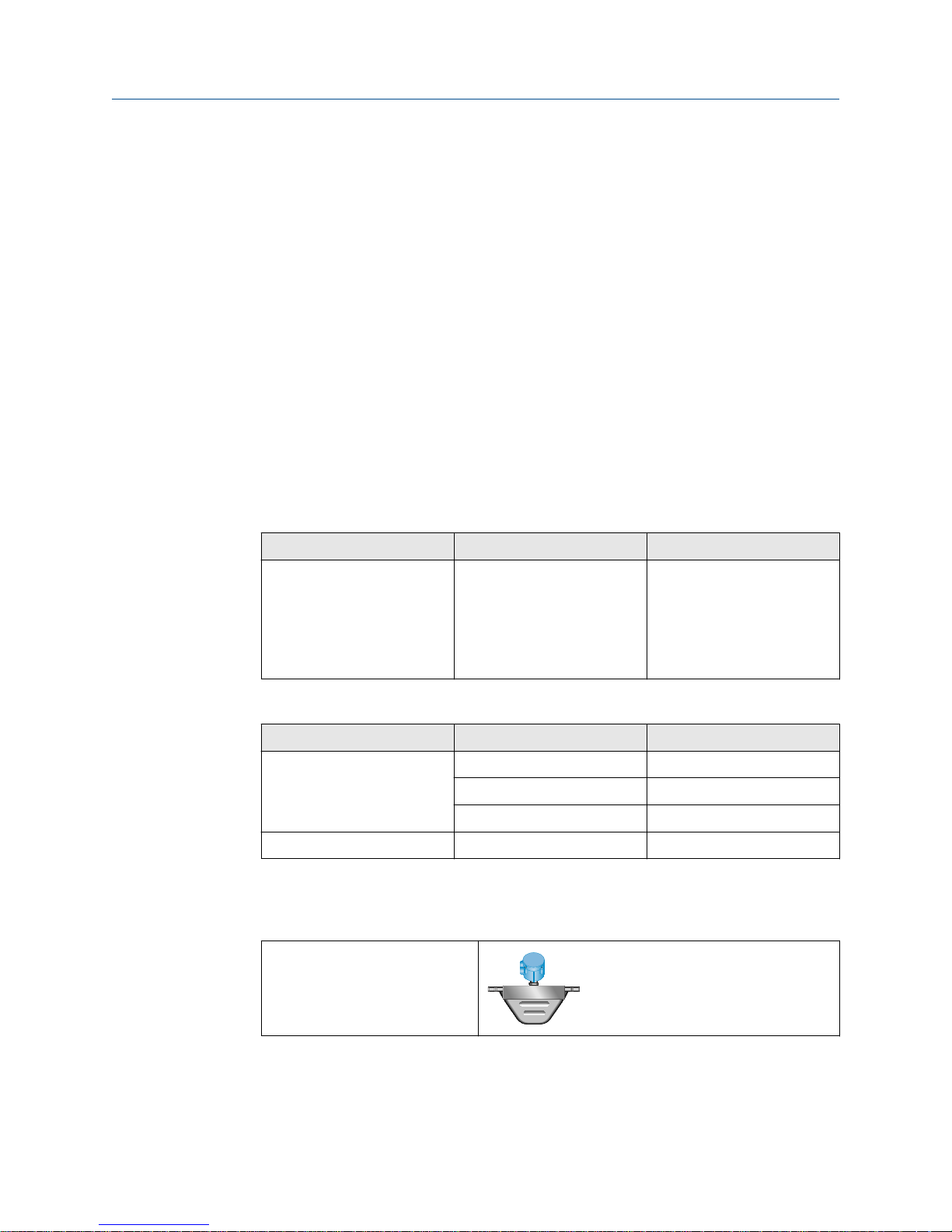
□ For optimal performance, install the sensor in the preferred orientation. The sensor will
work in any orientation as long as the flow tubes remain full of process fluid.
Table 1-3: Preferred sensor orientation
Liquids
Installation Manual 5
Planning
January 2019 20002346
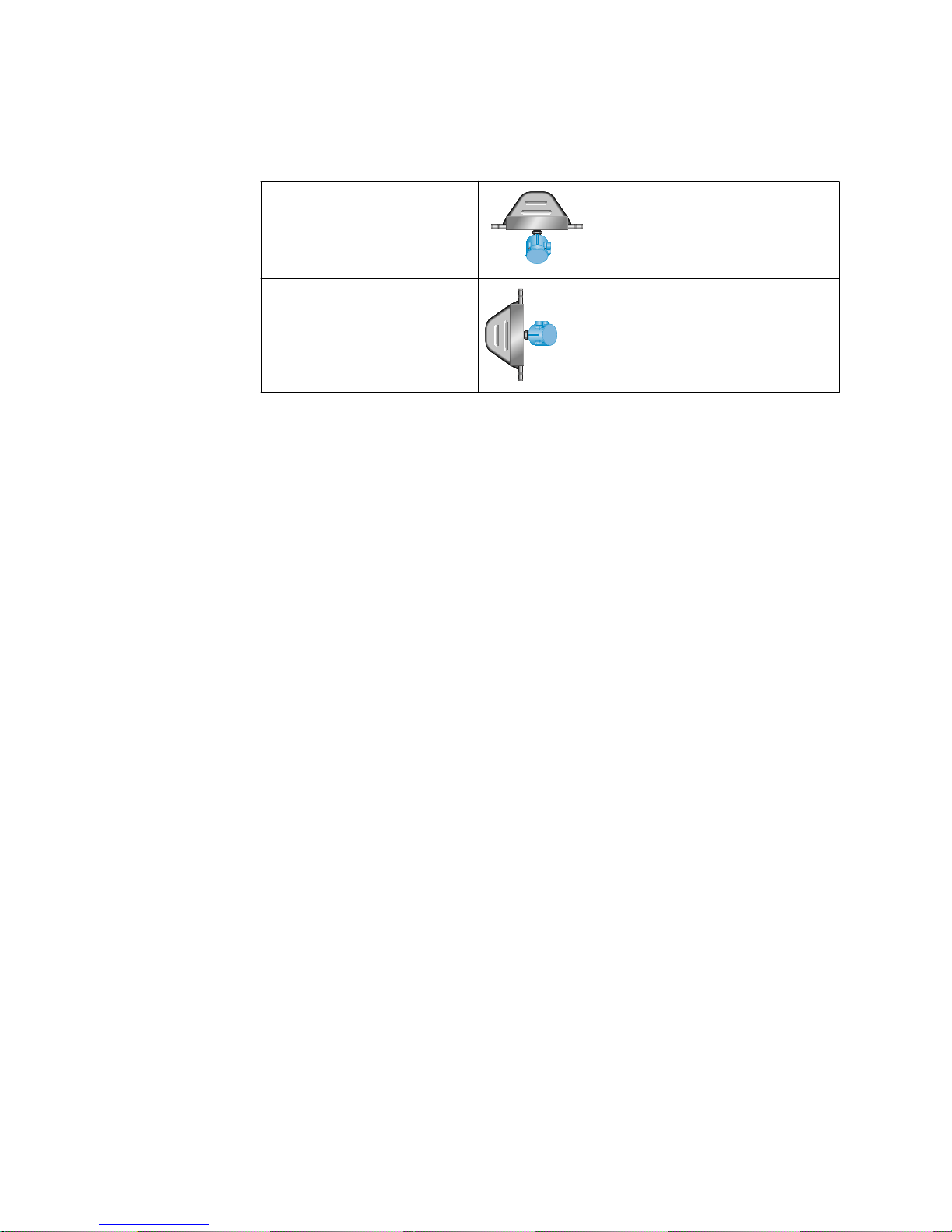
Table 1-3: Preferred sensor orientation (continued)
Gases
Slurries and self-draining
applications
Installation Manual
□ Install the meter so that the flow direction arrow on the sensor case matches the actual
forward flow of the process. (Flow direction is also software-selectable.)
1.2 Best practices
The following information can help you get the most from your sensor.
• There are no pipe run requirements for Micro Motion sensors. Straight runs of pipe
upstream or downstream are unnecessary.
• If the sensor is installed in a vertical pipeline, liquids and slurries should flow upward
through the sensor. Gases should flow downward.
• Keep the sensor tubes full of process fluid.
• For halting flow through the sensor with a single valve, install the valve downstream
from the sensor.
• Minimize bending and torsional stress on the meter. Do not use the meter to align
misaligned piping.
• The sensor does not require external supports. The flanges will support the sensor in
any orientation.
1.3 Temperature limits
Sensors can be used in the process and ambient temperature ranges shown in the
temperature limit graphs. For the purposes of selecting electronics options, temperature
limit graphs should be used only as a general guide. If your process conditions are close to
the gray area, consult with your Micro Motion representative.
Note
• In all cases, the electronics cannot be operated where the ambient temperature is
below -40 °F (-40.0 °C) or above 140 °F (60.0 °C). If a sensor is to be used where the
ambient temperature is outside of the range permissible for the electronics, the
electronics must be remotely located where the ambient temperature is within the
permissible range, as indicated by the shaded areas of the temperature limit graphs.
• Temperature limits may be further restricted by hazardous area approvals. Refer to the
hazardous area approvals documentation shipped with the sensor or available from the
Micro Motion H-Series Hygienic Coriolis Flow and Density Meters Product Data Sheet. For
further quesitons, contact customer service.
6 Micro Motion H-Series

400
(204)
81
(27)
–148
(–100)
Tproc
140 (60)
158 (70)
–40 (–40)
A
B
Tamb
Installation Manual
20002346 January 2019
Planning
• The extended-mount electronics option allows the sensor case to be insulated without
covering the transmitter, core processor, or junction box, but does not affect
temperature ratings. When insulating the sensor case at elevated process
temperatures (above 140 °F (60.0 °C)), please ensure electronics are not enclosed in
insulation as this may lead to electronics failure.
Ambient and process temperature limits for all H-Series meters
1.4 Recommendations for hygienic and selfdraining applications
H-Series sensors are self-draining when installed in a vertical pipeline.
For optimal cleanability and drainability:
• If possible, install the sensor in a vertical pipeline with the process fluid flowing upward
through the sensor.
• If the sensor must be installed in a horizontal pipeline, drainage is accomplished by air
purge evacuation of the pipeline circuit.
• For clean-in-place (CIP) applications, Micro Motion recommends using the generally-
accepted flow velocity of at least 1.5 m/s for cleaning the sensor.
• The gap between the electronics housing and sensor body should be inspected
periodically. Manually clean this gap when necessary.
• Tri-clamp and DIN 11851 style process connections require special gaskets to comply
with EHEDG requirements for hygienic design.
Installation Manual 7
A
B
C
Planning Installation Manual
January 2019 20002346
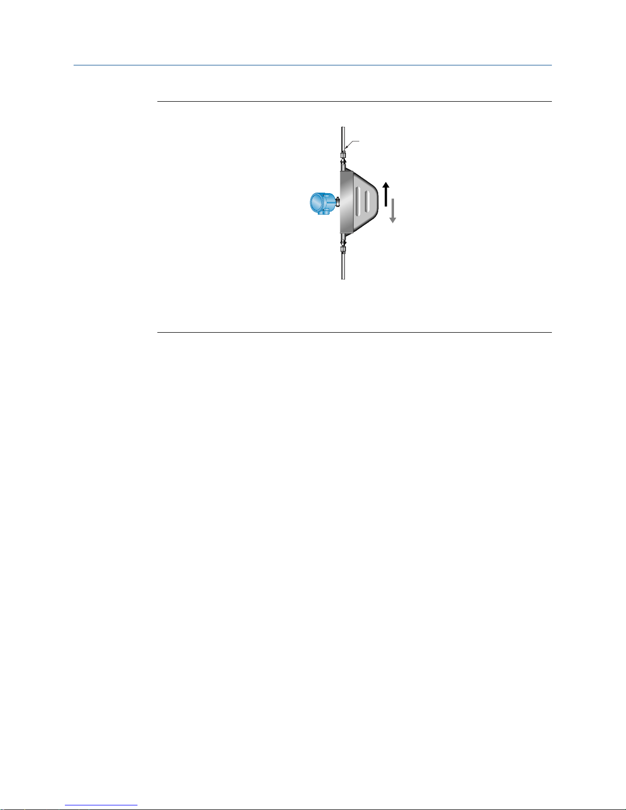
Figure 1-1: Installation for self-draining applications
A. Process pipeline
B. Direction of normal process flow
C. Direction of drainage
8 Micro Motion H-Series
 Loading...