

Page 1
Micro Motion® Fork Viscosity Meters
Direct insertion viscosity meter installation
Installation Manual
MMI-20020994, Rev AA
December 2013
Page 2

Safety and approval information
This Micro Motion product complies with all applicable European directives when properly installed in accordance with the
instructions in this manual. Refer to the EC declaration of conformity for directives that apply to this product. The EC declaration of
conformity, with all applicable European directives, and the complete ATEX Installation Drawings and Instructions are available on
the internet at www.micromotion.com or through your local Micro Motion support center.
Information affixed to equipment that complies with the Pressure Equipment Directive can be found on the internet at
www.micromotion.com/documentation.
For hazardous installations in Europe, refer to standard EN 60079-14 if national standards do not apply.
Other information
Full product specifications can be found in the product data sheet. Troubleshooting information can be found in the transmitter
configuration manual. Product data sheets and manuals are available from the Micro Motion web site at
www.micromotion.com/documentation.
Return policy
Micro Motion procedures must be followed when returning equipment. These procedures ensure legal compliance with
government transportation agencies and help provide a safe working environment for Micro Motion employees. Failure to follow
Micro Motion procedures will result in your equipment being refused delivery.
Information on return procedures and forms is available on our web support system at www.micromotion.com, or by phoning the
Micro Motion Customer Service department.
Micro Motion customer service
Email:
• Worldwide: flow.support@emerson.com
• Asia-Pacific: APflow.support@emerson.com
Telephone:
North and South America Europe and Middle East Asia Pacific
United States 800-522-6277 U.K. 0870 240 1978 Australia 800 158 727
Canada +1 303-527-5200 The Netherlands +31 (0) 318 495 555 New Zealand 099 128 804
Mexico +41 (0) 41 7686 111 France 0800 917 901 India 800 440 1468
Argentina +54 11 4837 7000 Germany 0800 182 5347 Pakistan 888 550 2682
Brazil +55 15 3413 8000 Italy 8008 77334 China +86 21 2892 9000
Venezuela +58 26 1731 3446 Central & Eastern +41 (0) 41 7686 111 Japan +81 3 5769 6803
Russia/CIS +7 495 981 9811 South Korea +82 2 3438 4600
Egypt 0800 000 0015 Singapore +65 6 777 8211
Oman 800 70101 Thailand 001 800 441 6426
Qatar 431 0044 Malaysia 800 814 008
Kuwait 663 299 01
South Africa 800 991 390
Saudia Arabia 800 844 9564
UAE 800 0444 0684
Page 3

Contents
Contents
Chapter 1 Planning ........................................................................................................................... 1
1.1 Installation checklist ........................................................................................................................1
1.2 Best practices ..................................................................................................................................2
1.3 Power requirements ........................................................................................................................2
1.4 Other installation considerations .................................................................................................... 4
1.5 Recommended installations for short-stem meters .........................................................................7
1.6 Perform a meter check (pre-installation) .........................................................................................9
Chapter 2 Mounting ........................................................................................................................11
2.1 Mount in free-stream application (flanged fitting) .........................................................................11
2.2 Mount in free-stream application (weldolet fitting) .......................................................................12
2.3 Mount with a T-piece (flanged fitting) ........................................................................................... 13
2.4 Mount with a flow-through chamber .............................................................................................15
2.5 Mount in an open tank (long-stem meter) .....................................................................................16
2.6 Mount in a closed tank (long-stem meter) .....................................................................................19
2.7 Attach the PFA ring and circlip .......................................................................................................24
2.8 Rotate the electronics on the meter (optional) ..............................................................................25
2.9 Rotate the display on the transmitter (optional) ............................................................................26
Chapter 3 Wiring ............................................................................................................................ 29
3.1 Available output terminals and wiring requirements ..................................................................... 29
3.2 Explosion-proof/flameproof or non-hazardous output wiring ........................................................30
3.3 Processor wiring for remote-mount 2700 FOUNDATION fieldbus™ option .................................... 34
3.4 Wiring to external devices (HART multidrop) ................................................................................ 39
3.5 Wiring to signal converters and/or flow computers .......................................................................41
Chapter 4 Grounding ...................................................................................................................... 43
Installation Manual i
Page 4

Contents
ii Micro Motion Fork Viscosity Meter
Page 5

1 Planning
Topics covered in this chapter:
• Installation checklist
• Best practices
• Power requirements
• Other installation considerations
• Recommended installations for short-stem meters
• Perform a meter check (pre-installation)
1.1 Installation checklist
Verify the contents of the product shipment to confirm you have all parts and
□
information necessary for the installation.
Verify the meter calibration range and boundary corresponds to the planned
□
installation. A calibration mismatch can cause measurement error, and will need to
be corrected.
Make sure that all electrical safety requirements are met for the environment in
□
which the meter will be installed.
Make sure that the local ambient and process temperatures and process pressure
□
are within the limits of the meter.
Make sure that the hazardous area specified on the approval tag is suitable for the
□
environment in which the meter will be installed.
Make sure that you will have adequate access to the meter for verification and
□
maintenance.
Verify that you have all equipment necessary for your installation. Depending on
□
your application, you may be required to install additional parts for optimal
performance of the meter.
If your meter will be wired to a remote-mount 2700 FOUNDATION fieldbus
□
transmitter:
- Refer to the instructions in this manual for preparing the 4-wire cable and wiring
to the processor connections.
- Refer to the instructions in the transmitter installation manual for mounting and
wiring the 2700 FOUNDATION fieldbus™ transmitter. See Micro Motion
Model 1700 and Model 2700 Transmitters: Installation Manual.
- Consider the maximum cable length between the meter and transmitter. The
maximum recommended distance between the two devices is 1000 ft (300 m).
Micro Motion recommends using Micro Motion cable.
Planning
™
Installation Manual 1
Page 6

Planning
1.2 Best practices
The following information can help you get the most from your meter.
• Handle the meter with care. Follow local practices for lifting or moving the meter.
• Perform a Known Density Verification (KDV) check of the meter prior to installing
the meter in your system.
• For the PFA-coated tines, always fit the protective cover over the tines when the
meter is not in use. The tine coating is not resistant to impact damage.
• Always store and transport the meter in its original packaging. For the long-stem
meters, be sure to include the transit cover secured by the grub screws.
• Do not use liquids incompatible with the materials of construction.
• Do not expose the meter to excessive vibration (greater than 0.5 g continuously).
Vibration levels in excess of 0.5 g can affect the meter accuracy.
• For optimal performance of the meter, ensure the operating conditions correspond
to the meter calibration range and boundary.
• Ensure all piping connections conform to the local and national regulations and
codes of practice.
• Ensure the transmitter housing cover is tightened properly after wiring to maintain
ingress protection and hazardous area approvals.
• Ensure the meter and associated pipework are pressure tested to 1½ times the
maximum operating pressure after installation.
• Thermally insulate the meter and the inlet and bypass-loop pipeline to maintain
stable temperatures.
1.3 Power requirements
Following are the DC power requirements to operate the meter:
• 24 VDC, 0.65 W typical, 1.1 W maximum
• Minimum recommended voltage: 21.6 VDC with 1000 ft of 24 AWG (300 m of
0.20 mm2) power-supply cable
• At startup, power source must provide a minimum of 0.5 A of short-term current at
a minimum of 19.6 V at the power input terminals.
2 Micro Motion Fork Viscosity Meter
Page 7
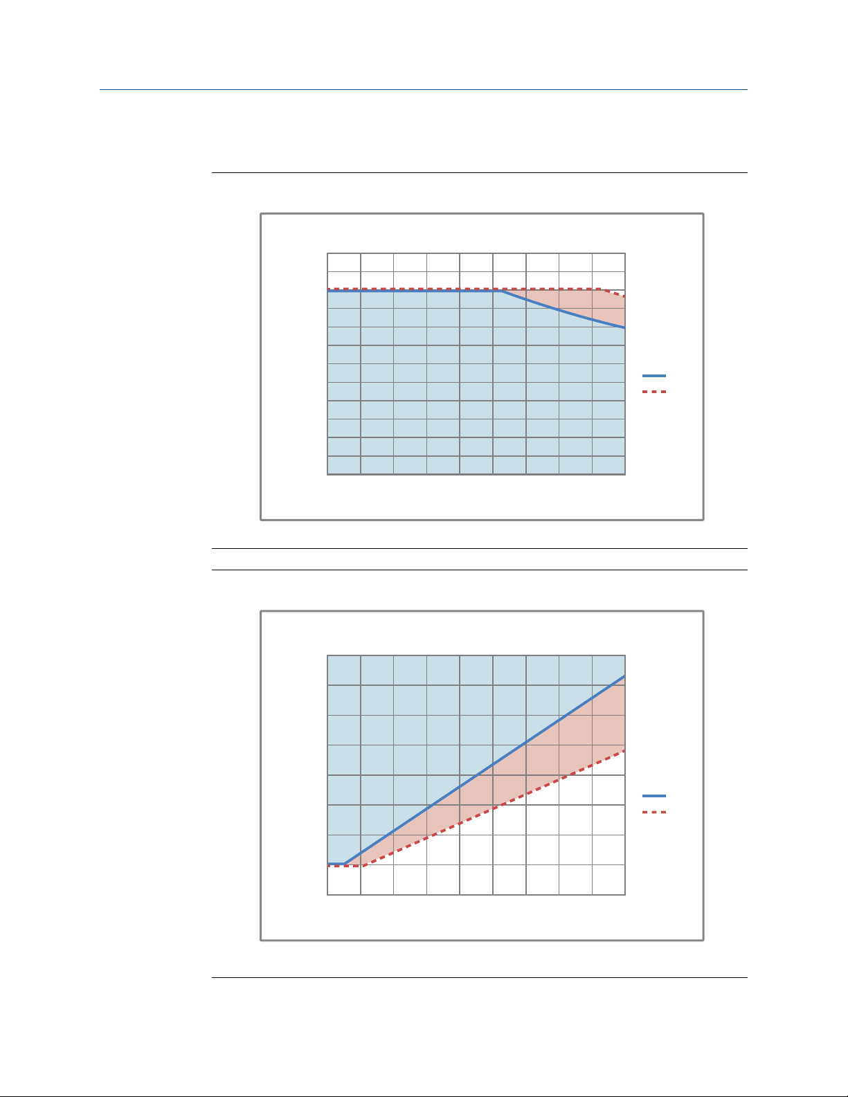
Power cable recommendations for explosion-proof/flameproof meters
300 600 900 1200 1500 1800 2100 2400 2700 3000
Distance of Installation (f t)
21.6V
24V
14
15
16
17
18
19
20
21
22
23
24
25
26
AWG Maximum
Minimum Wire Gauge
0.000
0.050
0.100
0.150
0.200
0.250
0.300
0.350
0.400
100 200 300 400 500 600 700 800 900 100 0
Minimum Wire Area (mm
2
)
Distance of Installation (m)
Minimum Wire Area (mm2)
21.6V
24V
Minimum wire gauge (AWG per feet)Figure 1-1:
Planning
Minimum wire area (mm2 per meter)Figure 1-2:
Installation Manual 3
Page 8

Planning
1.4 Other installation considerations
A variety of external factors exist that affect the ability of the meter to operate
successfully. To ensure that your system works correctly, consider the effects of these
factors when designing your installation.
1.4.1 Calibration boundaries
Important
Micro Motion calibrates all meters at the factory according to the sensor calibration range selected at
point of purchase. The factory calibration process takes into account the potential boundary effect of
the planned installation. At point of installation, confirm that the meter calibration range and
boundary matches the planned installation to ensure optimum performance of the meter. If the
meter calibration does not match the planned installation, measurement error may occur and you
will need to perform an onsite calibration.
The boundary effect of an installation refers to the sensitive, or effective, region of the
meter sensing device being interrupted by the boundary of the pipe walls. This effect can
vary based on the type of installation or the size of the pipeline diameter. Considering this
effect when calibrating the meter is important because the direct insertion meter can only
measure the properties of the fluid that are within the region that the meter is sensitive.
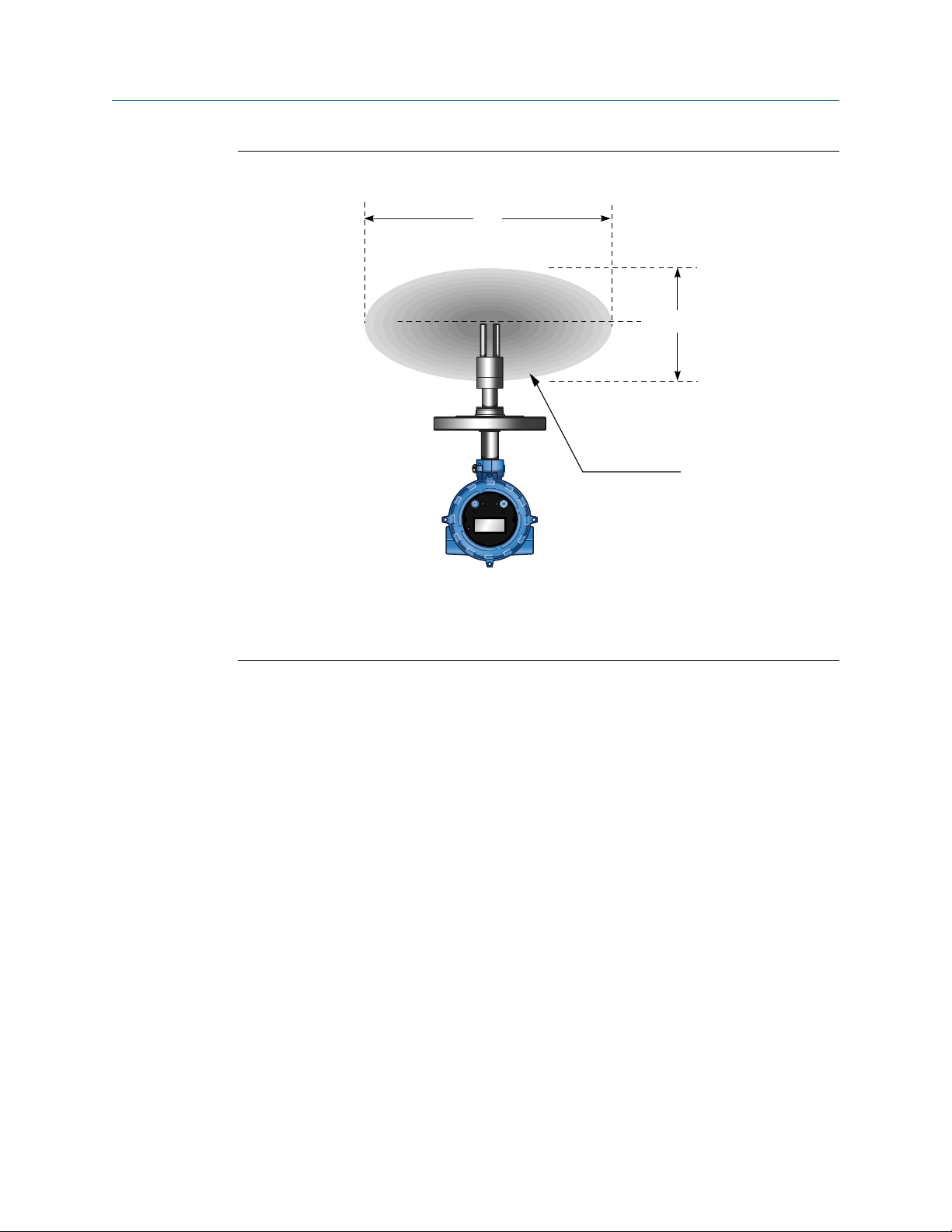
The vibration of the fork meter tines creates an effective measurement region that is
shaped as an ovoid centered on the tips of the tines. The long axis of the ovoid is aligned
with the direction that the tines are vibrating. The meter sensor is insensitive to any fluid
properties outside of this region, and progressively more sensitive to the fluid properties
the closer the fluid is to the meter tines (see Figure 1-3).
4 Micro Motion Fork Viscosity Meter
Page 9
B
A
C
STATUS
SCROLL SELECT
Planning
Region of measurement boundary or sensitivityFigure 1-3:
A. Long axis
B. Short axis
C. Sensitive, or effective, region
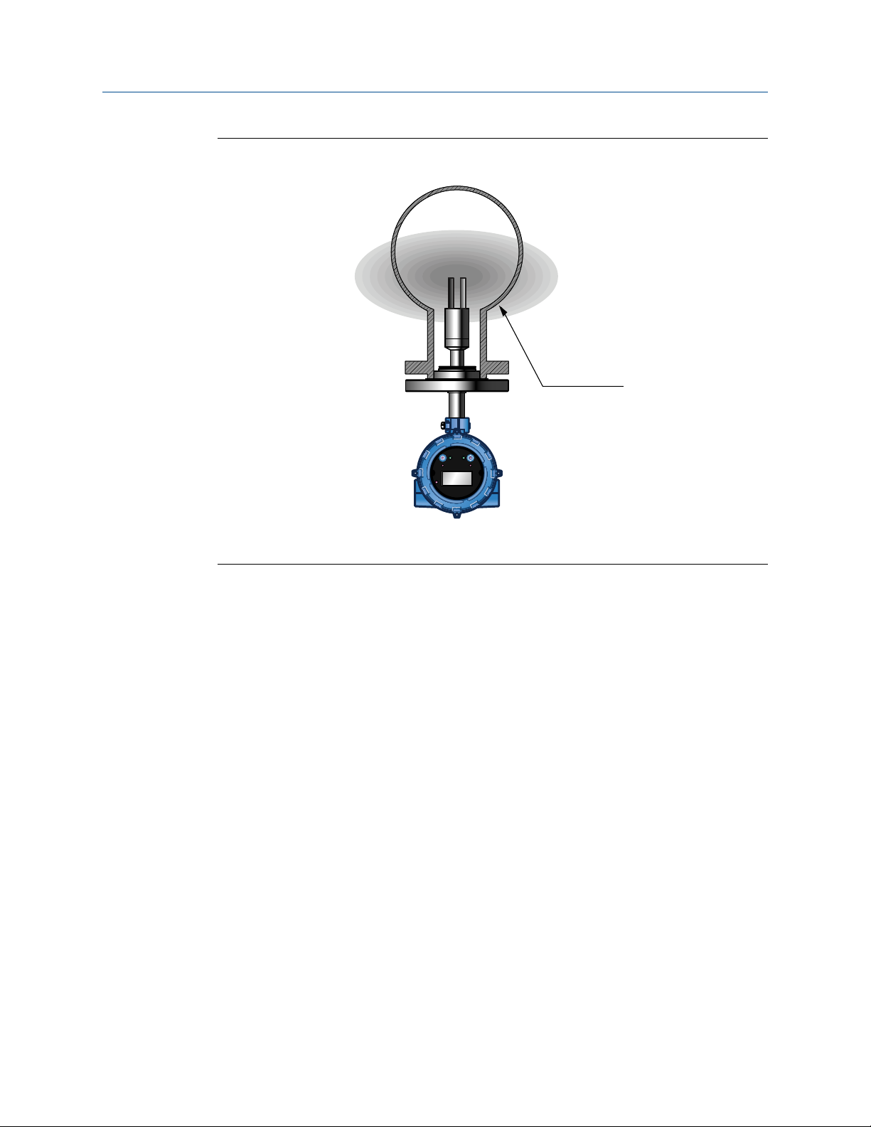
When installing the meter, if part of this effective region or volume is interfered with
because of the pipework or fittings a boundary effect exists (see Figure 1-4).
Installation Manual 5
Page 10
A
STATUS
SCROLL SELECT
Planning
Example of pipeline installation (with boundary effect)Figure 1-4:
A. Pipe walls interrupt effective region of meter sensitivity
1.4.2 Flow rate considerations
You must maintain flow rates and velocities to be relatively constant within the limits
specified for the meter. The fluid flow provides a steady heat flow into the meter
installation, and the flow rate influences the self-cleaning of the meter tines and the
dissipation of bubbles and solid contaminants around the meter.
If you install the meter in a bypass configuration (such as in a free-stream installation in a 4inch diameter horizontal bypass, or a flow-through chamber): you can maintain flow by
using a pressure drop, pitot scoop, or a sample pump. When using a sample pump, place
the pump upstream from the meter.
1.4.3 Entrained gas considerations
Entrained gas, or gas pockets, can disrupt the measurement of a fluid. A brief disruption in
the signal caused by transient gas pockets can be corrected in the meter configuration,
but you must avoid more frequent disruptions or serious gas entrainment to ensure
accurate and reliable fluid measurement.
To minimize the possibility of entrained gas:
• Keep pipe lines full of fluid at all times.
• Vent any gas prior to the meter installation location.
• Avoid sudden pressure drops or temperature changes which may cause dissolved
gases to break out of the fluid.
6 Micro Motion Fork Viscosity Meter
Page 11

• Maintain a back pressure on the system sufficient to prevent gas break out.
• Maintain flow velocity at the sensor within the specified limits.
1.4.4 Solids measurement considerations
Consider the following to avoid issues related to solids contamination:
• Avoid sudden changes of the fluid velocity that may cause sedimentation.
• Install the meter far enough downstream from any pipework configuration that may
cause centrifuging of solids (such as at a pipe bend).
• Maintain flow velocity at the meter installation that is within the specified limits.
• Use filtration in your process, if necessary.
1.4.5 Thermal effects considerations
For high viscosity fluids, you should minimize any temperature gradients in the fluid, and
in the piping and fittings immediately upstream and downstream of the meter. Minimizing
temperature gradients reduces the effect of viscosity changes. We recommend the
following to reduce the thermal effects to your meter installation:
• Always insulate the meter and surrounding pipework thoroughly.
- Insulation must be at least 1 inch (25 mm) of rockwool, preferably 2 inches (50
mm), or use an equivalent insulating heat jacket.
- Insulation must be enclosed in a sealed protective casing to prevent moisture
ingress, air circulation, and crushing of the insulation.
- For flow-through chamber installations, Micro Motion provides a special
insulation jacket because of the opportunity for low volumetric flow rates
(hence, low heat flow) and increased vulnerability to temperature effects.
• Avoid direct heating or cooling of the meter and associated pipe work upstream and
downstream that is likely to create temperature gradients.
• If it is necessary to provide protection against cooling because of loss of flow, you
can apply electrical trace heating. This type of heating must be thermostatically
controlled, and the thermostat must be set to operate below the minimum
operating temperature of the system.
Planning
1.5 Recommended installations for short-stem meters
Micro Motion recommends three standard installations for the short-stem meter to
alleviate any need for onsite calibration. All meters are factory calibrated for these types of
installations and take into consideration the potential boundary effect of each installation.
Table 1-1 highlights these different installations according to specific conditions or
requirements that may exist for your process environment.
Installation Manual 7
Page 12

Planning
Standard installation types: short-stem metersTable 1-1:
Installation type: Free stream T-Piece
Meter placement Meter tines are
inserted directly into
the main fluid flow.
The meter must always
be installed
horizontally and with
the tines oriented to
allow flow through or
between the gap of
the tines.
Flow rate 0.3 to 0.5 m/s (at the
meter)
Viscosity Up to 500 cP Up to 100 cP (250 cP in
Temperature –50 °C to 200 °C (–58
°F to 392 °F)
Main flow pipe size • Horizontal pipe:
minimum
diameter, 100 mm
(4 inch)
• Vertical pipe:
minimum
diameter, 150 mm
(6 inch)
Advantages • Simple installation
in large bore pipes
• Ideal for clean
fluids and nonwaxing oils
• Suitable for line
viscosity
measurement and
simple referrals
Meter tines are
contained in a side
pocket off the main
flow. The meter must
always be installed
horizontally and with
the tines oriented to
allow flow through or
between the gap of
the tines.
0.5 to 3 m/s (at main
pipe wall)
some cases)
–50 °C to 200 °C (–58
°F to 392 °F)
Minimum diameter,
100 mm (4 inch)
• Simple installation
in large bore pipes
• Ideal for clean
fluids and nonwaxing oils
• Suitable for line
viscosity
measurement and
simple referrals
Flow-through
chamber
Meter tines are
contained in a flowthrough chamber in
which fluid is
circulated from the
main flow.
10 to 30 l/min
Up to 500 cP
–50 °C to 200 °C (–58
°F to 392 °F)
Suitable for all sizes, if
mounted in a bypass
(slipstream)
configuration
• Adaptable
installation to any
diameter main
pipe and for tank
applications
• Ideal for flow and
temperature
conditioning
• Suitable for
complex referrals
and for use with
heat exchangers
• Suitable for step
changes in
viscosity
• Fast response
• Ideal for analyzer
cubicles
8 Micro Motion Fork Viscosity Meter
Page 13

Standard installation types: short-stem meters (continued)Table 1-1:
Installation type: Free stream T-Piece
Recommendations Do not use with:
• Dirty fluids
• Low or unstable
flow rates
• Where step
changes in
viscosity can occur
• For small bore
pipes
Do not use with:
• Dirty fluids
• Low or unstable
flow rates
• Where step
changes in
viscosity can occur
• For small bore
pipes
• Where
temperature
effects are
significant
Planning
Flow-through
chamber
• Do not use with
uncontrolled flow
rates.
• Careful system
design is required
to ensure
representative
measurement.
• Frequently requires
the use of a pump.
1.6 Perform a meter check (pre-installation)
Micro Motion® recommends that you perform a check of the meter prior to installation.
This check confirms that no damage occurred to the meter during shipment.
1. Remove the meter from the box.
CAUTION!
Handle the meter with care. Follow local practices for lifting or moving the meter.
2. Visually inspect the meter for any physical damage.
If you notice any physical damage to the meter, immediately contact Micro Motion
Customer Support at flow.support@emerson.com.
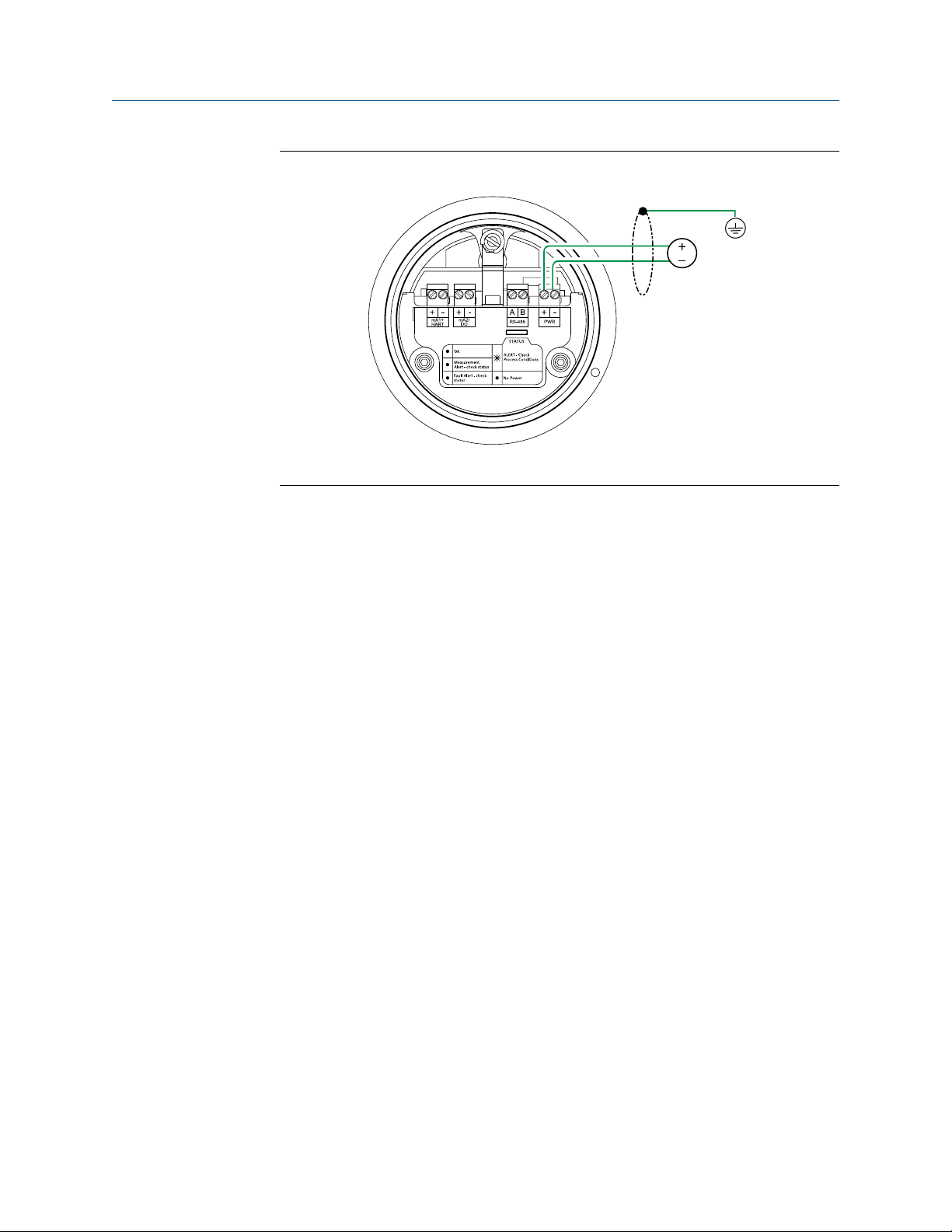
3. Connect and power up the meter.
You must remove the back transmitter housing cover to access the PWR terminals.
Installation Manual 9
Page 14
A
Planning
Power supply wiring terminalsFigure 1-5:
A. 24 VDC
4. Perform a Known Density Verification (KDV) check.
The Known Density Verification procedure is used to verify that the meter's current
operation matches the factory calibration. If the meter passes the test, then it has
not drifted or changed since its factory calibration.
For more information on performing a KDV check, see the configuration and use
manual that shipped with the product.
10 Micro Motion Fork Viscosity Meter
Page 15

2 Mounting
Topics covered in this chapter:
• Mount in free-stream application (flanged fitting)
• Mount in free-stream application (weldolet fitting)
• Mount with a T-piece (flanged fitting)
• Mount with a flow-through chamber
• Mount in an open tank (long-stem meter)
• Mount in a closed tank (long-stem meter)
• Attach the PFA ring and circlip
• Rotate the electronics on the meter (optional)
• Rotate the display on the transmitter (optional)
Mounting
2.1 Mount in free-stream application (flanged
fitting)
Prerequisites
Free-stream (flanged) installations are recommended for processes with the following
conditions:
Flow 0.3 to 0.5 m/s (at the meter)
Viscosity 0.5 to 12,500 cP
Temperature -50 °C to 200 °C (–58 °F to 392 °F)
-40 °C to 200 °C (-40 °F to 392 °F) in hazardous
areas
Procedure
See Figure 2-1 for information on installing the meter (with a flanged fitting) in a freestream application.
Important
You must always install the meter horizontally and oriented to allow flow in the gap between the
tines, irrespective of the pipeline orientation (horizontal or vertical). This position helps to prevent
the trapping of bubbles or solids on the meter – allowing the solids to sink and the bubbles to rise.
Installation Manual 11
Page 16

B
A
STATUS
SCROLL SELECT
Plan view of a vertical pipe installation
Mounting
Free-stream (flanged fitting) meter installationFigure 2-1:
A. 4-inch pipe for horizontal installations; 6-inch (152 mm) pipe for vertical installations
B. Size the recess mount so that the meter tines are inserted fully into the liquid [approximately 2.75 in
(70 mm)].
2.2 Mount in free-stream application (weldolet fitting)
The weldolet for free-stream installations has a 1.5-inch taper lock fitting and is supplied to
be welded on 4-inch, 6-inch, 8-inch or 10-inch pipelines. A weldolet installation ensures
that the tines of the meter are oriented correctly and are fully inserted into the fluid
stream.
Prerequisites
• Free-stream (weldolet) installations are recommended for processes with the
following conditions:
Flow 0.3 to 0.5 m/s (at the meter)
Viscosity 0.5 to 12,500 cP
Temperature –50 °C to 200 °C (–58 °F to 392 °F)
–40 °C to 200 °C (–40 °F to 392 °F) in
hazardous areas
Note
If temperature variations are a critical factor in your process, the reduced thermal mass of the
taper-lock fitting of the weldolet can track changes in temperature more efficiently.
• Before fitting the weldolet, you must bore a 2.1 in (52.5 mm) diameter opening in
the pipeline to accept the meter. You must weld the weldolet to the pipeline
concentrically with the pre-bored hole.
12 Micro Motion Fork Viscosity Meter
Page 17

STATUS
SCROLL SELECT
A
C
D
B
Plan view of a vertical pipe installation
Mounting
Procedure
See Figure 2-2 for information on installing the meter (with a weldolet fitting) in a freestream application.
Important
You must always install the meter horizontally and oriented to allow flow in the gap between the
tines, irrespective of the pipeline orientation (horizontal or vertical). This position helps to prevent
the trapping of bubbles or solids on the meter – allowing the solids to sink and the bubbles to rise.
Free-stream (weldolet fitting) meter installationFigure 2-2:
A. 4-inch pipe for horizontal installations; 6-inch (152 mm) pipe for vertical installations
B. 2.1 in (52.5 mm) meter opening in pipeline
C. Weld
D. Free-stream weldolet (purchased to fit pipe diameter)
2.3 Mount with a T-piece (flanged fitting)
Prerequisites
• T-piece (flanged) installations are recommended for processes with the following
conditions:
Flow 0.3 to 0.5 m/s (at the pipe wall)
Viscosity 0.5 to 100 cP
Temperature - -50 °C to 200 °C (–58 °F to 392 °F)
- -40 °C to 200 °C (-40 °F to 392 °F) in
hazardous areas
Installation Manual 13
Page 18

STATUS
SCROLL SELECT
B
A
C
Plan view of a vertical pipe installation
Mounting
Note
- Flow velocity at the pipe wall and fluid viscosity must be within the limits shown to ensure
that the fluid within the pocket is refreshed in a timely manner. This installation will not
respond as rapidly as the free-stream installation to step changes in viscosity.
- The thermal mass of the flanges may affect the response time of the meter to
temperature changes.
• Attach the PFA ring and circlip to the underside of the meter flange before installing
the meter in your application (see Section 2.7).
Procedure
See Figure 2-3 for information on installing the meter (with a flanged fitting) in a T-piece.
Size the T-piece so that the meter tines are retracted 1 in (25 mm) from the main pipe wall.
For higher flow rates, increase this by 0.4 in (10 mm) for every 1 m/s increase in the main
flow rate.
Important
You must always install the meter horizontally and oriented to allow flow in the gap between the
tines, irrespective of the pipeline orientation (horizontal or vertical). This position helps to prevent
the trapping of bubbles or solids on the meter – allowing the solids to sink and the bubbles to rise.
T-piece (flanged fitting) meter installationFigure 2-3:
A. 4-inch pipe or larger for horizontal or vertical installations
B. Distance of meter tines from main pipe wall is determined by the maximum flow rate of the process.
C. PFA ring and circlip
14 Micro Motion Fork Viscosity Meter
Page 19

2.4 Mount with a flow-through chamber
Flow-through chambers are manufactured by Micro Motion, and are available with either
weld-prepared ends or with flange or compression fittings for connection into the process
pipelines. They are available with 1- inch NB, 2-inch NB, or 3-inch NB inlet and outlet pipes.
Important
The length of the inlet and outlet pipes must not be altered, otherwise the temperature response
and stability of the fitting may be adversely affected.
Prerequisites
Installations in flow-through chambers are recommended for processes with the following
conditions:
Flow Constant
• 10–30 l/min for 2-inch Schedule 40
calibration bore section
• 5–300 l/min for 3-inch Schedule 80
calibration bore section
Viscosity 0.5 to 1000 cP
Temperature –50 °C to 200 °C (–58 °F to 392 °F)
–40 °C to 200 °C (–40 °F to 392 °F) in hazardous
areas
Pressure 70 bar @ 204 °C, subject to process connections
Mounting
Important
• Flow velocity at the pipe wall and fluid viscosity must be within the limits shown to ensure
that the fluid within the pocket is refreshed in a timely manner. This installation will not
respond as rapidly as the free-stream installation to step changes in viscosity.
• The thermal mass of the flanges may affect the response time of the meter to temperature
changes.
Procedure
See Figure 2-4 for an example installation of a meter in a flow-through chamber.
Installation Manual 15
Page 20

A
Mounting
Flow-through chamber meter installationFigure 2-4:
A. Optional temperature port
Note
• This flow-through chamber is a direct-insertion type chamber that does not have a thermowell and
uses a ¾-inch Swagelok connection.
• The three compression fittings on the flow pockets (½-inch drain, ¾-inch temperature probe, and 1-½-
inch mounting nut for the meter) are rated to above the working pressure of the flow pocket. The
fittings may be Swagelok or Parker.
2.5 Mount in an open tank (long-stem meter)
CAUTION!
Only the safe area version of the long-stem meter can be mounted in an open tank.
Procedure
1. Clamp the long-stem meter to a structure, positioning the clamp to determine the
insertion depth of the meter.
16 Micro Motion Fork Viscosity Meter
Page 21

B
A
A
B
Mounting
Open-tank meter installation (long stem)Figure 2-5:
2. Confirm the meter tines are away from the tank wall.
Meter placement (away from tank wall)Figure 2-6:
A. 50 mm
B. 200 mm
3. Confirm the meter tines are immersed in fluid.
Installation Manual 17
Page 22

AA
Mounting
Meter placement (immersed in fluid)Figure 2-7:
4. Confirm the meter tines are placed away from objects and disturbed flow.
Meter placement (distance from objects and disturbed flow)Figure 2-8:
A. 200 mm
5. If flow exists, confirm the meter tines are aligned so that the flow is directed towards
or through the gap between the tines.
18 Micro Motion Fork Viscosity Meter
Page 23

Meter placement (flow direction through tine gap)Figure 2-9:
6. Confirm the meter tines are kept away from deposit buildup.
Mounting
Meter placement (away from deposit buildup)Figure 2-10:
2.6 Mount in a closed tank (long-stem meter)
1. Attach the long-stem meter using the fitted flange attachment (shipped with the
product).
Installation Manual 19
Page 24

Mounting
Closed-tank installation (fitted flange attachment)Figure 2-11:
2. (Optional) To vary the insertion depth of the meter, mount the meter on a standoff
section that attaches to the flange (not provided).
20 Micro Motion Fork Viscosity Meter
Page 25

B
A
A
B
Mounting
Closed-tank installation (with standoff)Figure 2-12:
A. Standoff height can vary (provided by customer)
3. Confirm the meter tines are away from the tank wall.
Meter placement (away from tank wall)Figure 2-13:
A. 50 mm
B. 200 mm
4. Confirm the meter tines are immersed in fluid.
Installation Manual 21
Page 26

A
A
Mounting
Meter placement (immersed in fluid)Figure 2-14:
5. Confirm the meter placement has allowed for the flexing of the tank lid to prevent
the meter from being pushed towards a tank wall or into the path of disturbed flow.
Meter placement (allowance for tank lid flexing)Figure 2-15:
A. 200 mm
6. Confirm the meter tines are placed away from objects and disturbed flow.
22 Micro Motion Fork Viscosity Meter
Page 27

AA
Mounting
Meter placement (distance from objects and disturbed flow)Figure 2-16:
A. 200 mm
7. If flow exists, confirm the meter tines are aligned so that the flow is directed towards
or through the gap between the tines.
Meter placement (flow direction through tine gap)Figure 2-17:
8. Confirm the meter tines are kept away from deposit buildup.
Installation Manual 23
Page 28

Mounting
Meter placement (away from deposit buildup)Figure 2-18:
2.7 Attach the PFA ring and circlip
You attach the PFA ring (and circlip) around the boss on the underside of the meter flange
to center the meter tines within a 2-inch Schedule 40 or 80 pipe. The circlip holds the ring
in place.
Note
If you are using the Zirconium version of the meter, a self-locking PFA ring is provided and does not
require a circlip to keep it in place.
Procedure
See Figure 2-19 for information on attaching the PFA ring and circlip to the meter.
24 Micro Motion Fork Viscosity Meter
Page 29

Attaching a PFA ring and circlipFigure 2-19:
B
A
C
A
A. Circlip (not provided with self-locking PFA rings)
B. PFA ring
C. PFA ring and circlip attached
Mounting
2.8 Rotate the electronics on the meter (optional)
You can rotate the transmitter on the meter up to 90°.
1. Using a 4 mm hex key, loosen the cap screw that holds the transmitter in place.
Component to secure transmitter in placeFigure 2-20:
A. M5 socket-head cap screw
2. Rotate the transmitter clockwise to the desired orientation up to 90°.
3. Secure the cap screw in place and tighten to 60 lb·in (6.8 N·m).
Installation Manual 25
Page 30

B
C
D
A
D
E
Mounting
2.9 Rotate the display on the transmitter (optional)
The display on the transmitter electronics module can be rotated 90° or 180° from the
original position.
Display componentsFigure 2-21:
A. Transmitter housing
B. Sub-bezel
C. Display module
D. Display screws
E. Display cover
Procedure
1. Power down the meter.
2. Turn the display cover counterclockwise to remove it from the main enclosure.
3. Carefully loosen (and remove if necessary) the semi-captive display screws while
holding the display module in place.
4. Carefully pull the display module out of the main enclosure until the sub-bezel pin
terminals are disengaged from the display module.
Note
If the display pins come out of the board stack with the display module, remove the pins and
reinstall them.
5. Rotate the display module to the desired position.
6. Insert the sub-bezel pin terminals into the display module pin holes to secure the
display in its new position.
26 Micro Motion Fork Viscosity Meter
Page 31

Mounting
7. If you have removed the display screws, line them up with the matching holes on the
sub-bezel, then reinsert and tighten them.
8. Place the display cover onto the main enclosure.
9. Turn the display cover clockwise until it is snug.
10. Power up the meter.
Installation Manual 27
Page 32

Mounting
28 Micro Motion Fork Viscosity Meter
Page 33

3 Wiring
Topics covered in this chapter:
• Available output terminals and wiring requirements
• Explosion-proof/flameproof or non-hazardous output wiring
• Processor wiring for remote-mount 2700 FOUNDATION fieldbus™ option
• Wiring to external devices (HART multidrop)
• Wiring to signal converters and/or flow computers
3.1 Available output terminals and wiring
requirements
Three pairs of wiring terminals are available for transmitter outputs. These outputs vary
depending on your transmitter output option ordered. The Analog (mA), Time Period
Signal (TPS), and Discrete (DO) outputs require external power, and must be connected to
an independent 24 VDC power supply.
Wiring
For meters connecting to a remote-mount 2700 FOUNDATION fieldbus™ transmitter, you
must wire the meter to the remote-mount 2700 transmitter using a 4-wire cable
connection. See the processor wiring content in this manual for information on how to
wire the meter. Refer to the transmitter installation manual for information on wiring the
remote-mount 2700 FOUNDATION fieldbus™ transmitter.
The screw connectors for each output terminal accept a maximum wire size of 14 AWG
(2.5 mm2).
Important
• Output wiring requirements depend on whether the meter will be installed in a safe area or a
hazardous area. It is your responsibility to verify that the specific installation meets the local
and national safety requirements and electrical codes.
• If you will configure the meter to poll an external temperature or pressure device, you must
wire the mA output to support HART communications. You may use either HART/analog
single-loop wiring or HART multi-drop wiring.
Available transmitter outputsTable 3-1:
Output channels
Transmitter version
Analog 4–20 mA + HART 4–20 mA Modbus/RS-485
Discrete 4–20 mA + HART Discrete output Modbus/RS-485
Processor for remote-mount 2700
FOUNDATION fieldbus
™
A B C
Disabled Disabled Modbus/RS-485
Installation Manual 29
Page 34

Wiring
3.2 Explosion-proof/flameproof or non-hazardous output wiring
3.2.1 Wire the Analog outputs version in an explosion-proof/ flameproof or non-hazardous area
CAUTION!
Meter installation and wiring should be performed by suitably trained personnel only in
accordance with the applicable code of practice.
Procedure
Wire to the appropriate output terminal and pins (see Figure 3-1).
30 Micro Motion Fork Viscosity Meter
Page 35

mA1+
HART
RS-485
PWR
mA2
AA
B
RS-485 A
RS-485 B
C
D
B
B
A
A
A
Wiring
Wiring the Analog outputs versionFigure 3-1:
A. 24 VDC
B. R
(250 Ω resistance)
load
C. HART-compatible host or controller; and/or signal device
D. Signal device
Note
For operating the milliamp outputs with a 24V supply, a maximum total loop resistance of 657
Ω
allowed.
CAUTION!
• To meet the EC Directive for EMC (Electromagnetic Compatibility), it is recommended that the
meter be connected using a suitable instrumentation cable. The instrumentation cable should
have individual screen(s), foil or braid over each twisted pair and an overall screen to cover all
cores. Where permissible, the overall screen should be connected to earth at both ends (360°
bonded at both ends). The inner individual screen(s) should be connected at only one end, the
controller end.
• Metal cable glands should be used where the cables enter the meter amplifier box. Unused cable
ports should be fitted with metal blanking plugs.
Installation Manual 31
is
Page 36

Wiring
3.2.2 Wire the Discrete output version in an explosion-proof/ flameproof or non-hazardous area
CAUTION!
Meter installation and wiring should be performed by suitably trained personnel only in
accordance with the applicable code of practice.
Procedure
Wire to the appropriate output terminal and pins (see Figure 3-2).
32 Micro Motion Fork Viscosity Meter
Page 37

mA1+
HART
RS-485
PWR
DO
AA
B
RS-485 A
RS-485 B
C
E
D
B
A
A
A
Wiring
Wiring the Discrete output versionFigure 3-2:
A. 24 VDC
B. R
(250 Ω resistance)
load
C. HART-compatible host or controller; and/or signal device
Ω
D. R
load
E. Discrete input device
Note
resistance recommended)
(500
• For operating the milliamp output with a 24V supply, a maximum total loop resistance of 657 Ω is
allowed.
• When operating the Discrete output with a 24 VDC power supply, a maximum total loop resistance of
Ω
is allowed.
1300
CAUTION!
• To meet the EC Directive for EMC (Electromagnetic Compatibility), it is recommended that the
meter be connected using a suitable instrumentation cable. The instrumentation cable should
have individual screen(s), foil or braid over each twisted pair and an overall screen to cover all
cores. Where permissible, the overall screen should be connected to earth at both ends (360°
bonded at both ends). The inner individual screen(s) should be connected at only one end, the
controller end.
Installation Manual 33
Page 38

Wiring
• Metal cable glands should be used where the cables enter the meter amplifier box. Unused cable
ports should be fitted with metal blanking plugs.
3.3 Processor wiring for remote-mount 2700
FOUNDATION fieldbus™ option
3.3.1 RS-485 entity parameters for the remote-mount 2700
FOUNDATION fieldbus™ option
DANGER!
Hazardous voltage can cause severe injury or death. To reduce the risk of hazardous voltage,
shut off power before wiring the meter.
DANGER!
Improper wiring in a hazardous environment can cause an explosion. Install the meter only in
an area that complies with the hazardous classification tag on the meter.
RS-485 output and cable entity parametersTable 3-2:
Cable parameters for intrinsically safe circuit (linear)
Voltage (Ui) 17.22 VDC
Current (Ii) 484 mA
Maximum capacitance (Ci) 1 nF
Maximum inductance (Li) Negligible
Cable parameters for Ex ib IIB, Ex ib IIC
Voltage (Uo) 9.51 VDC
Current (instantaneous) (Io) 480 mA
Current (steady state) (I) 106 mA
Power (Po) 786 mW
Internal resistance (Ri) 19.8 Ω
Cable parameters for Group IIC
Maximum external capacitance (Co) 85 nF
Maximum external inductance (Lo) 25 µH
Maximum external inductance/resistance ratio
(Lo/Ro)
31.1 µH/Ω
Cable parameters for Group IIB
Maximum external capacitance (Co) 660 nF
34 Micro Motion Fork Viscosity Meter
Page 39

RS-485 output and cable entity parameters (continued)Table 3-2:
Maximum external inductance (Lo) 260 µH
Maximum external inductance/resistance ratio
(Lo/Ro)
3.3.2 Prepare the 4-wire cable
Important
For user-supplied cable glands, the gland must be capable of terminating the drain wires.
Note
If you are installing unshielded cable in continuous metallic conduit with 360º termination shielding,
you only need to prepare the cable – you do not need to perform the shielding procedure.
Wiring
124.4 µH/Ω
Installation Manual 35
Page 40

Wiring
4-wire cable preparationFigure 3-3:
Remove the core processor
cover
Cable glands
Micro Motion
cable gland
Pass the wires through the gland nut and clamping insert.
Gland nut
1. Strip 4-1/2 inch (115 mm) of cable jacket.
2. Remove the clear wrap and filler material.
3. Strip all but 3/4 inch (19 mm) of shielding.
Clamping
insert
NPT
Wrap the drain wires twice around the shield and cut off
Gland supplier
Gland type
the excess drain wires.
Cable layout
through the gland.
Terminate the drain
wires inside the
M20
1. Strip 4-1/4 inch (108 mm) of cable jacket.
2. Remove the clear wrap and filler material.
3. Strip all but 1/2 inch (12 mm) of shielding.
User-supplied
cable gland
Pass the wires
gland.
Metal conduit
Run conduit to
sensor
Lay cable in conduit
Done
(do not perform the
shielding procedure)
Drain wires
wrapped around
shield
Go to the shielding
procedure
36 Micro Motion Fork Viscosity Meter
Page 41

Wiring
4-wire cable shieldingFigure 3-4:
From the preparation
procedure
Micro Motion
cable gland
Braided
(armored cable)
Apply the Heat Shrink
1. Slide the shielded heat shrink over the drain wires. Ensure that the
wires are completely covered.
2. Apply heat (250 °F or 120 °C) to shrink the tubing. Do not burn the
cable.
3. Position the clamping insert so the interior end is flush with the braid
of the heat shrink.
Assemble the Gland
1. Fold the shield or braid back over the clamping insert and 1/8 inch
(3 mm) past the O-ring.
2. Install the gland body into the conduit opening on the core processor housing.
3. Insert the wires through gland body and tighten the gland nut onto the gland body.
Cable shield
type
Shielded heat
shrink
Foil
(shielded cable)
NPT
Gland supplier
Gland type M20
After heat applied
User-supplied
cable gland
Trim 7 mm from the shielded
heat shrink
Trim
Terminate the shield
and drain wires in the
Assemble the gland
according to vendor
gland
instructions
Shield folded back
Done
Gland body
4-wire cable types and usage
Micro Motion offers two types of 4-wire cable: shielded and armored. Both types contain
shield drain wires.
The 4-wire cable supplied by Micro Motion consists of one pair of red and black 18 AWG
(0.75 mm2) wires for the VDC connection, and one pair of white and green 22 AWG
(0.35 mm2) wires for the RS-485 connection.
User-supplied 4-wire cable must meet the following requirements:
Installation Manual 37
Page 42

A
B
C
D
Wiring
• Twisted pair construction.
• Applicable hazardous area requirements, if the core processor is installed in a
hazardous area.
• Wire gauge appropriate for the cable length between the core processor and the
transmitter.
• Wire gauge of 22 AWG or larger, with a maximum cable length of 1000 feet.
3.3.3 Processor wiring for the remote-mount 2700
FOUNDATION fieldbus™ option
The following figure illustrates how to connect the individual wires of a 4-wire cable to the
processor terminals. For detailed information on mounting and wiring to the remotemount 2700 FOUNDATION fieldbus transmitter, see the transmitter installation manual.
Figure 3-5:
Processor (Modbus/RS-485) connections to the remote-mount 2700 FF
transmitter
A. White wire to RS-485/A terminal
B. Green wire to RS-485/B terminal
C. Red wire to Power supply (+) terminal
D. Black wire to Power supply (–) terminal
Important
• To meet the EC Directive for EMC (Electromagnetic Compatibility), it is recommended that the
meter be connected using a suitable instrumentation cable. The instrumentation cable should have
individual screen(s), foil or braid over each twisted pair and an overall screen to cover all cores.
Where permissible, the overall screen should be connected to earth at both ends (360° bonded at
both ends). The inner individual screen(s) should be connected at only one end, the controller end.
• Metal cable glands should be used where the cables enter the meter amplifier box. Unused cable
ports should be fitted with metal blanking plugs.
38 Micro Motion Fork Viscosity Meter
Page 43

3.4 Wiring to external devices (HART multidrop)
You can wire up to three external HART devices with the meter. The following information
provides wiring diagrams for making those connections in safe and hazardous
environments.
Wiring
Installation Manual 39
Page 44

250 Ω
24 VDC
mA1+
HART
A
B
C
E
D
Wiring
3.4.1 Wire external HART devices in an explosion-proof/ flameproof or non-hazardous area
Wiring external devices in an explosion-proof/flameproof or non-hazardous areaFigure 3-6:
A. HART Device 1
B. HART Device 2
C. HART Device 3
D. Meter (mA+/HART output)
E. HART/Field Communicator
CAUTION!
• To meet the EC Directive for EMC (Electromagnetic Compatibility), it is recommended that the meter be connected
using a suitable instrumentation cable. The instrumentation cable should have individual screen(s), foil or braid
over each twisted pair and an overall screen to cover all cores. Where permissible, the overall screen should be
connected to earth at both ends (360° bonded at both ends). The inner individual screen(s) should be connected at
only one end, the controller end.
• Metal cable glands should be used where the cables enter the meter amplifier box. Unused cable ports should be
fitted with metal blanking plugs.
40 Micro Motion Fork Viscosity Meter
Page 45

3.5 Wiring to signal converters and/or flow computers
For meters with a Time Period Signal (TPS) output, you can wire the meter to an signal
converter or flow computer directly. The following information provides wiring diagrams
for making those connections in safe and hazardous environments.
When wiring the meter to an active HART host or signal converter/flow computer, you are
not required to provide external power to the output connections. These active devices
provide the 24 VDC necessary for these connections.
Wiring
Installation Manual 41
Page 46

mA1+
HART
RS-485
PWR
TPS
AA
B
24 VDC
RS-485 A
RS-485 B
A
B
Wiring
3.5.1 Wire to a signal converter/flow computer in an explosion-proof/flameproof or non-hazardous area
Figure 3-7:
Wiring to a signal converter/flow computer in an explosion-proof/
flameproof or non-hazardous area
A. Active HART host
B. Active signal converter/flow computer
CAUTION!
• To meet the EC Directive for EMC (Electromagnetic Compatibility), it is recommended that
the meter be connected using a suitable instrumentation cable. The instrumentation cable
should have individual screen(s), foil or braid over each twisted pair and an overall screen to
cover all cores. Where permissible, the overall screen should be connected to earth at both
ends (360° bonded at both ends). The inner individual screen(s) should be connected at only
one end, the controller end.
• Metal cable glands should be used where the cables enter the meter amplifier box. Unused
cable ports should be fitted with metal blanking plugs.
42 Micro Motion Fork Viscosity Meter
Page 47

4 Grounding
The meter must be grounded according to the standards that are applicable at the site.
The customer is responsible for knowing and complying with all applicable standards.
Prerequisites
Micro Motion suggests the following guides for grounding practices:
• In Europe, EN 60079-14 is applicable to most installations, in particular Sections
12.2.2.3 and 12.2.2.4.
• In the U.S.A. and Canada, ISA 12.06.01 Part 1 provides examples with associated
applications and requirements.
• For IECEx installations, IEC 60079-14 is applicable.
If no external standards are applicable, follow these guidelines to ground the meter:
• Use copper wire, 18 AWG (0.75 mm2) or larger wire size.
• Keep all ground leads as short as possible, less than 1 Ω impedance.
• Connect ground leads directly to earth, or follow plant standards.
Grounding
CAUTION!
Ground the meter to earth, or follow ground network requirements for the facility. Improper
grounding can cause measurement error.
Procedure
Check the joints in the pipeline or tank installation.
- If the joints in the pipeline or tank are ground-bonded, the meter is automatically
grounded and no further action is necessary (unless required by local code).
- If the joints in the pipeline or tank are not grounded, connect a ground wire to the
grounding screw located on the meter electronics.
Installation Manual 43
Page 48

Grounding
44 Micro Motion Fork Viscosity Meter
Page 49

Grounding
Installation Manual 45
Page 50

Micro Motion Inc. USA
Worldwide Headquarters
7070 Winchester Circle
Boulder, Colorado 80301
T +1 303-527-5200
T +1 800-522-6277
F +1 303-530-8459
www.micromotion.com
Micro Motion Europe
Emerson Process Management
Neonstraat 1
6718 WX Ede
The Netherlands
T +31 (0) 318 495 555
F +31 (0) 318 495 556
www.micromotion.nl
*MMI-20020994*
MMI-20020994
Rev AA
2013
Micro Motion Asia
Emerson Process Management
1 Pandan Crescent
Singapore 128461
Republic of Singapore
T +65 6777-8211
F +65 6770-8003
Micro Motion United Kingdom
Emerson Process Management Limited
Horsfield Way
Bredbury Industrial Estate
Stockport SK6 2SU U.K.
T +44 0870 240 1978
F +44 0800 966 181
Micro Motion Japan
Emerson Process Management
1-2-5, Higashi Shinagawa
Shinagawa-ku
Tokyo 140-0002 Japan
T +81 3 5769-6803
F +81 3 5769-6844
©
2013 Micro Motion, Inc. All rights reserved.
The Emerson logo is a trademark and service mark of Emerson
Electric Co. Micro Motion, ELITE, ProLink, MVD and MVD Direct
Connect marks are marks of one of the Emerson Process
Management family of companies. All other marks are property of
their respective owners.
 Loading...