

Emerson Micro Motion 7835, Micro Motion7845 Installation Manual
Installation Manual
MMI-20020999, Rev AC
May 2018
Micro Motion® Compact Density Meter (CDM)
7835/7845 Liquid Density Meter Retrofit Installation
Safety and approval information
This Micro Motion product complies with all applicable European directives when properly installed in accordance with the
instructions in this manual. Refer to the EU declaration of conformity for directives that apply to this product. The EU declaration of
conformity, with all applicable European directives, and the complete ATEX Installation Drawings and Instructions are available on
the internet at www.emerson.com or through your local Micro Motion support center.
Information affixed to equipment that complies with the Pressure Equipment Directive, can be found on the internet at
www.emerson.com.
For hazardous installations in Europe, refer to standard EN 60079-14 if national standards do not apply.
Other information
Full product specifications can be found in the product data sheet. Troubleshooting information can be found in the configuration
manual. Product data sheets and manuals are available from the Micro Motion web site at www.emerson.com.
Return policy
Follow Micro Motion procedures when returning equipment. These procedures ensure legal compliance with government
transportation agencies and help provide a safe working environment for Micro Motion employees. Micro Motion will not accept
your returned equipment if you fail to follow Micro Motion procedures.
Return procedures and forms are available on our web support site at www.emerson.com, or by phoning the Micro Motion Customer
Service department.
Emerson Flow customer service
Email:
• Worldwide: flow.support@emerson.com
• Asia-Pacific: APflow.support@emerson.com
Telephone:
North and South America Europe and Middle East Asia Pacific
United States 800-522-6277 U.K. 0870 240 1978 Australia 800 158 727
Canada +1 303-527-5200 The Netherlands +31 (0) 704 136 666 New Zealand 099 128 804
Mexico +41 (0) 41 7686 111 France 0800 917 901 India 800 440 1468
Argentina +54 11 4837 7000 Germany 0800 182 5347 Pakistan 888 550 2682
Brazil +55 15 3413 8000 Italy 8008 77334 China +86 21 2892 9000
Central & Eastern +41 (0) 41 7686 111 Japan +81 3 5769 6803
Russia/CIS +7 495 981 9811 South Korea +82 2 3438 4600
Egypt 0800 000 0015 Singapore +65 6 777 8211
Oman 800 70101 Thailand 001 800 441 6426
Qatar 431 0044 Malaysia 800 814 008
Kuwait 663 299 01
South Africa 800 991 390
Saudi Arabia 800 844 9564
UAE 800 0444 0684

Contents
Contents
Chapter 1 Planning ...........................................................................................................................1
1.1 Retrofit installation overview ..........................................................................................................1
1.2 Installation checklist .......................................................................................................................1
1.3 Best practices .................................................................................................................................2
1.4 Pressure drop in the meter ............................................................................................................. 3
1.5 Power requirements .......................................................................................................................5
1.6 Spacing requirements .................................................................................................................... 9
1.7 Perform a pre-installation meter check .........................................................................................11
Chapter 2 Removing a 7835/7845 meter ........................................................................................ 12
2.1 Disconnect the 7835/7845 meter wiring ......................................................................................12
2.2 Remove the meter from the pipeline ............................................................................................14
Chapter 3 Mounting .......................................................................................................................15
3.1 Mount the meter ..........................................................................................................................15
3.2 Rotate the electronics on the meter (optional) .............................................................................16
3.3 Rotate the display on the transmitter (optional) ...........................................................................17
Chapter 4 Wiring ........................................................................................................................... 19
4.1 Wiring to external devices (HART multidrop) ................................................................................19
4.2 Terminals and wiring requirements .............................................................................................. 19
4.3 Retrofit wiring: terminal-to-output conversions ........................................................................... 20
4.4 Explosion-proof/flameproof or non-hazardous output wiring .......................................................22
4.5 Intrinsically safe output wiring ......................................................................................................26
4.6 Processor wiring for remote-mount 2700 FOUNDATION™ fieldbus option ....................................34
4.7 Wiring to signal converters and/or flow computers ...................................................................... 39
Chapter 5 Grounding ......................................................................................................................42
Installation Manual i

Contents
ii Micro Motion Compact Density Meter 7835/7845 Retrofit
1 Planning
Topics covered in this chapter:
Retrofit installation overview
•
Installation checklist
•
Best practices
•
Pressure drop in the meter
•
Power requirements
•
Spacing requirements
•
Perform a pre-installation meter check
•
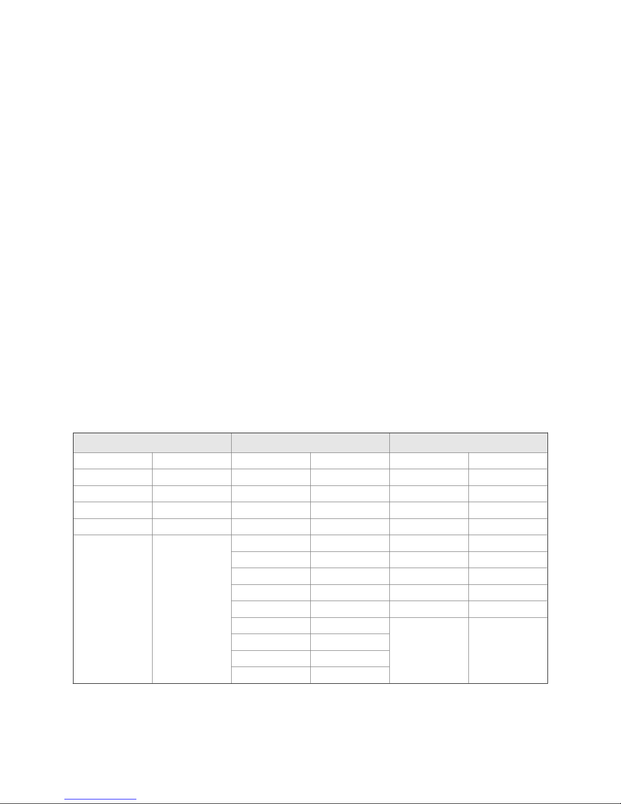
1.1 Retrofit installation overview
Following is an overview of the tasks required to install the Compact Density Meter (CDM)
as a replacement to the Micro Motion 7835/7845 liquid density meter. We recommend
that you review this information before beginning the retrofit installation.
Planning
Process
Confirm you have all parts necessary and meet the basic installation requirements.
Consider the installation best practices for the removal and installation of your meter(s).
Confirm any additional wiring, external power supplies, and/or
resistance needed to wire to the CDM.
Remove the existing 7835/7845 liquid density meter. See Chapter 2
Mount the CDM retrofit meter. See Chapter 3
Wire the meter according to the recommended practices for
your process environment and required approvals.
Ground the meter. See Grounding
1.2 Installation checklist
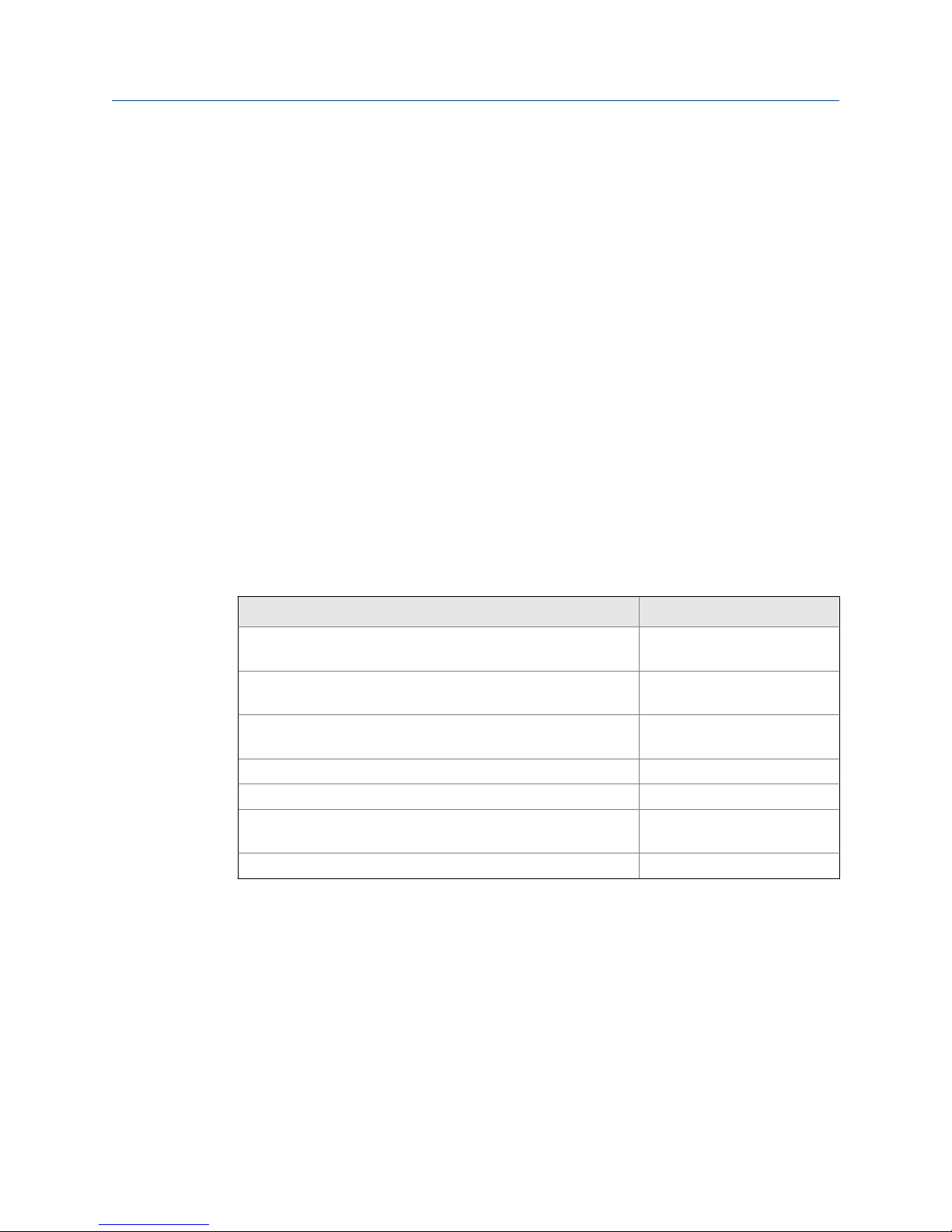
□
Make sure that the hazardous area specified on the approval tag is suitable for the
environment in which the meter will be installed.
□
Verify that the local ambient and process temperatures are within the limits of the
meter.
□
Verify the spacing requirements for the retrofit meter installation (see Section 1.6).
Reference
See Section 1.2
See Section 1.3
See Chapter 4
See Chapter 4
Installation Manual 1

Planning
□
Verify the retrofit wiring requirements, which may vary depending on your existing
transmitter configuration:
- Confirm the CDM input/output wiring requirements (see Chapter 4).
Tip
Depending on your current configuration, you may need additional wiring or can reuse
wiring that had been connected to devices no longer needed.
- For intrinsically safe hazardous area installations, you must purchase new barriers
or isolators. You cannot reuse existing safety barriers or galvanic isolators for
connecting to the CDM.
Tip
Micro Motion provides safety barrier and galvanic isolator installation kits for wiring the
CDM in a hazardous environment. These kits provide the appropriate barriers or isolators
depending on the outputs available and approvals required. Contact
flow.support@emerson.com for more information on ordering these kits.
□
If your meter will be wired to a remote-mount 2700 FOUNDATION™ fieldbus
transmitter:
- Refer to the instructions in this manual for preparing the 4-wire cable and wiring
to the processor connections. See Section 4.6.
- Refer to the instructions in the transmitter installation manual for mounting and
wiring the 2700 FOUNDATION™ fieldbus transmitter.
- Consider the maximum cable length between the meter and transmitter. The
maximum recommended distance between the two devices is 1000 ft (300 m).
Micro Motion recommends using Micro Motion cable.
□
Install the meter so that the flow direction arrow on the meter case matches the
actual forward flow of the process. (Flow direction is also software-selectable.)
□
For optimal performance, thermally insulate the meter and the inlet and bypassloop pipeline to maintain stable temperatures.
Tip
Micro Motion offers a soft, weather-proof insulating jacket that is easily fitted to all CDM
versions.
1.3
2 Micro Motion Compact Density Meter 7835/7845 Retrofit
Best practices
The following information can help you get the most from your meter.
• Handle the meter with care. Follow local practices for lifting or moving the meter.
• Perform a Known Density Verification (KDV) check of the meter prior to installing
the meter in your system.
• Install the meter in the preferred orientation in a vertical pipeline with liquids and
slurries flowing upward.

Planning
Important
If you do not install the meter in the preferred orientation, you may need to apply a field
offset to ensure optimal performance. Refer to your organizational standards for sampling
and reference measurement to determine what the offset may be.
• If you are installing the meter into an application configuration requiring differential
pressure, confirm the current configuration is suitable for the CDM.
• Do not apply a compression force greater than 200 lbs (90.7 kg) when installing the
meter.
• Thermally insulate the meter and the inlet and bypass-loop pipeline to maintain
stable temperatures.
• There are no pipe run requirements for Micro Motion meters. Straight runs of pipe
upstream or downstream are unnecessary.
• Keep the meter tubes full of process fluid.
• For halting flow through the meter with a single valve, install the valve downstream
from the meter.
• Minimize bending and torsional stress on the meter. Do not use the meter to align
misaligned piping.
• The meter does not require external supports. The flanges will support the meter in
any orientation.
• For bypass configurations using a pump, install the pump downstream of the meter
to avoid pump heat transfer.
• For bypass configurations, maintain a target flow through the meter to ensure
sample integrity and consistent temperature with the main line.
1.4
Installation Manual 3
Pressure drop in the meter
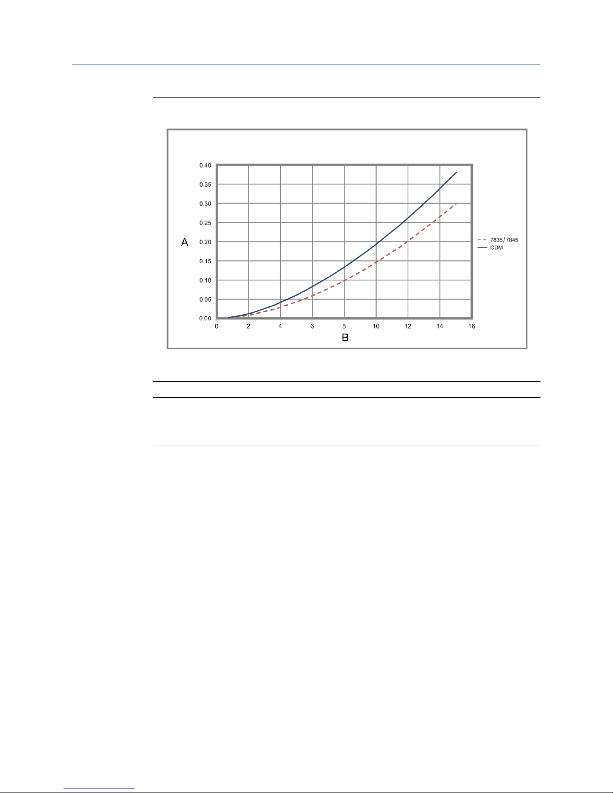
The pressure drop in the meter depends on the process conditions. The following figures
illustrate the pressure drop for the meter at varying fluid density and viscosity. In addition,
these charts show how the meter compares to the Micro Motion 7835/7845 liquid density
meters.
Important
For the most accurate pressure drop calculations using your process variables, use the Micro Motion
product selector available at www.emerson.com.
Planning
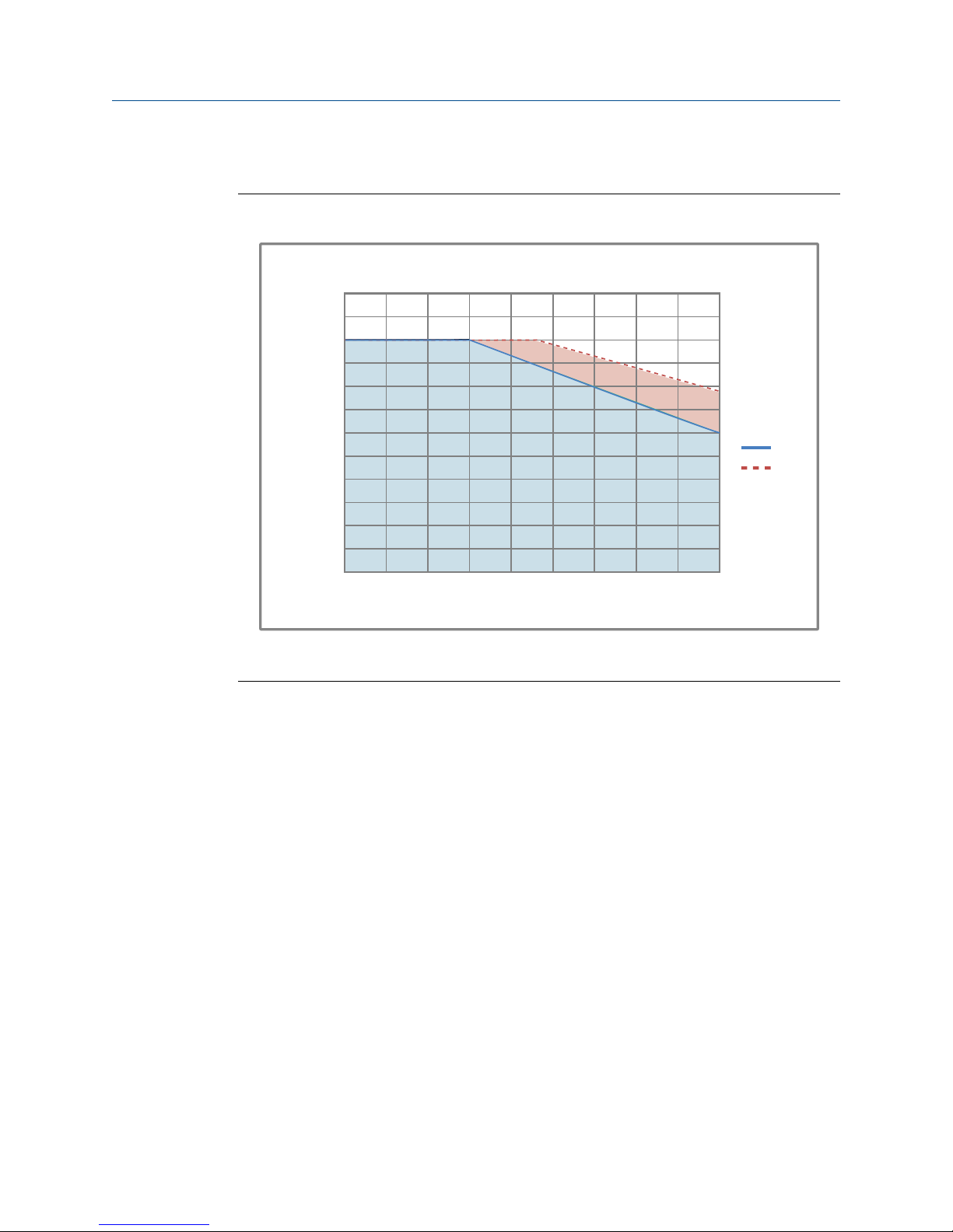
Sample pressure drop calculations (fluid viscosity equals 2 cP)Figure 1-1:
A. Pressure drop (bar)
B. Flow rate (m3/hr)
Note
• Density = 800 kg/m
• Viscosity = 2 cP
3
4 Micro Motion Compact Density Meter 7835/7845 Retrofit

Planning
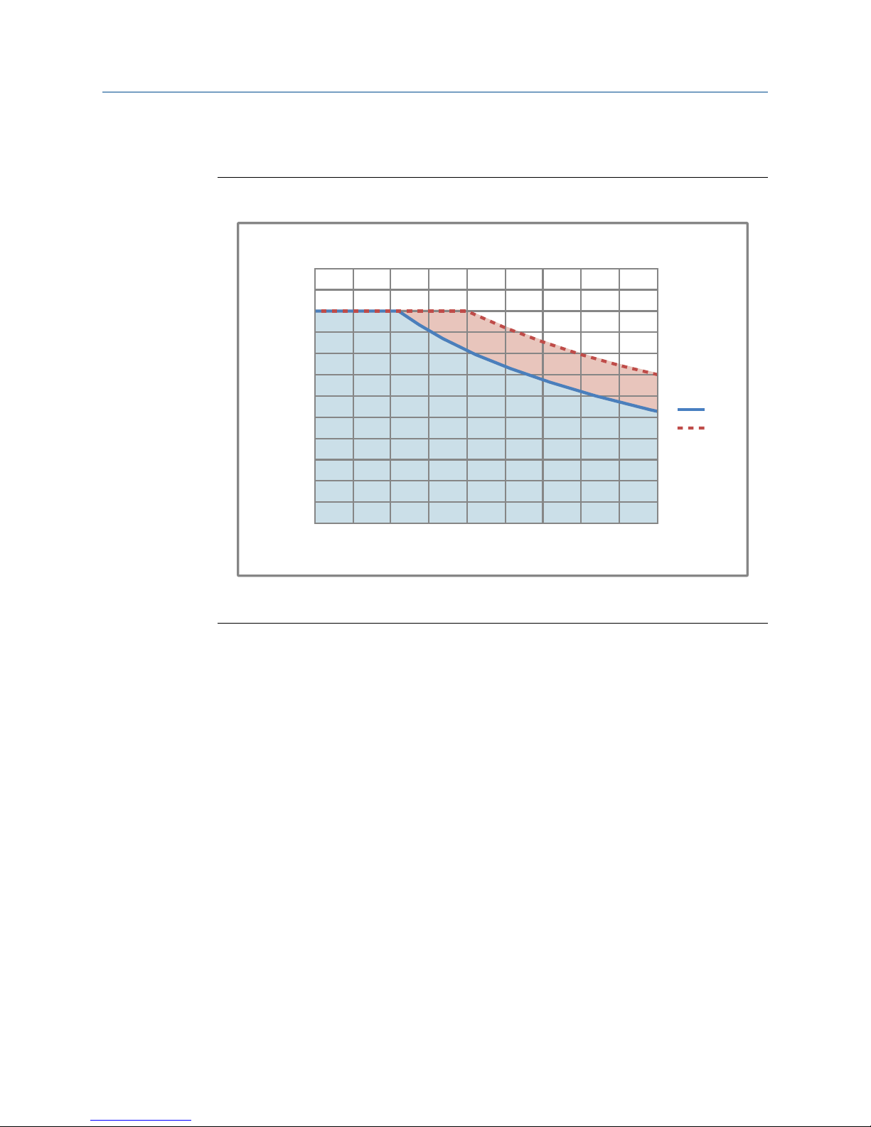
Sample pressure drop calculations (fluid viscosity equals 10 cP)Figure 1-2:
1.5
A. Pressure drop (bar)
B. Flow rate (m3/hr)
Note
• Density = 800 kg/m
• Viscosity = 10 cP
3
Power requirements
Following are the DC power requirements to operate the meter:
• Explosion-proof/flameproof meters:
- 24 VDC, 0.65 W typical, 1.1 W maximum
- Minimum recommended voltage: 21.6 VDC with 1000 ft of 24 AWG (300 m of
0.20 mm2) power-supply cable
- At startup, power source must provide a minimum of 0.5 A of short-term current
at a minimum of 19.6 V at the power-input terminals.
• Intrinsically safe meters:
- 24 VDC, 0.7 W typical with 250 Ω barrier, 0.96 W maximum with 250 Ω barrier
- Minimum recommended voltage: 22.8 VDC with 1000 ft of 22 AWG (300 m of
0.25 mm2) power-supply cable
Installation Manual 5
300ft 600ft 900ft 1200ft 1500ft 1800ft 2100ft 2400ft 2700ft 3000ft
B
2 1 . 6V
24 V
14
15
16
17
18
19
20
21
22
23
24
25
26
A
91.44m 182.88m 274.32m 365.76m 457.2m 548.64m 640.08m 731.52m 822.96m 914.4m
Planning
Power cable recommendations for explosion-proof/flameproof meters
Minimum wire gauge (AWG per feet )Figure 1-3:
A. AWG maximum
B. Distance of installation
6 Micro Motion Compact Density Meter 7835/7845 Retrofit

0
. 00 0
0.100
0.200
0.300
0.400
0.500
0.600
0.700
10 0m 20 0m 30 0m 40 0m 50 0m 60 0m 70 0m 80 0m 90 0m 100 0m
B
2 1 . 6V
24 V
A
328.084 ft 656.168ft 984.253ft 1312.34ft 1640.42ft 1968.5ft 2296.59ft 2624.67ft 2952.76ft 3280.84ft
Planning
Minimum wire area (mm2 per meter)Figure 1-4:
A. Minimum wire area (mm2)
B. Distance of installation
Installation Manual 7
3 0 0 6 0 0 9 0 0 12 0 0 1 50 0 18 0 0 21 0 0 24 0 0 27 0 0 3 00 0
22 . 8 V
24 V
14
15
16
17
18
19
20
21
2 2
23
24
25
26
A
B
Planning
Power cable recommendations for intrinsically safe meters
Minimum wire gauge (AWG per feet)Figure 1-5:
A. AWG
B. Distance of installation
8 Micro Motion Compact Density Meter 7835/7845 Retrofit
Planning
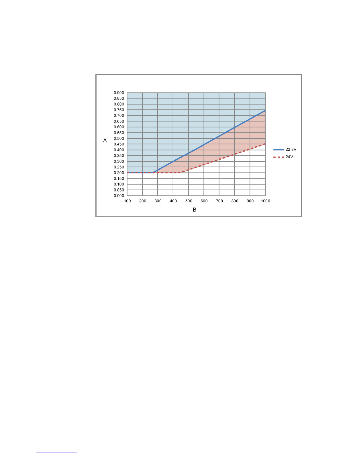
Minimum wire area (mm2 per meter)Figure 1-6:
1.6
A. Minimum wire area (mm2)
B. Distance of installation
Spacing requirements
When determining spacing requirements, be sure to consider the height requirements of
the CDM in relation to the existing 7835/7845 meter (see Figure 1-8).
Installation Manual 9
12.6
(320)
Dimensions in
inches
(mm)
Explosion Proof 7835
Intrinsically Safe 7835/7845
6.2
(158.6)
Planning
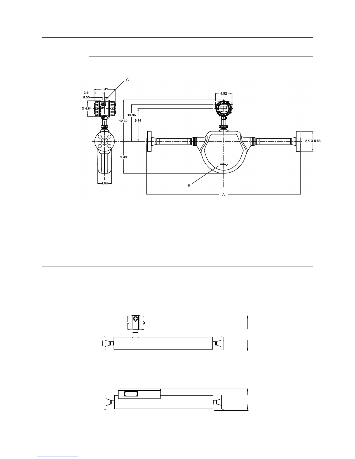
CDM retrofit meter dimensionsFigure 1-7:
A. Dim. A — face to face is up to 40.4 inches (1026 mm) ± 0.125 in (3 mm)
B. Nominal flow direction — the meter can be configured for normal (forward), reversed, or bi-
directional flow
C. 2x 1/2-14 NPT female electronic interface
Note
Drawing dimensions are in inches.
7835/7845 meter dimensions (height only)Figure 1-8:
10 Micro Motion Compact Density Meter 7835/7845 Retrofit
1.7 Perform a pre-installation meter check
MTL7728P+
3
4
1
2
A
Check the meter prior to installation to confirm that no damage occurred to the meter
during shipment.
Procedure
1. Remove the meter from the box.
CAUTION!
Handle the meter with care. Follow all corporate, local, and national safety regulations
for lifting and moving the meter.
2. Visually inspect the meter for any physical damage.
If you notice any physical damage to the meter, immediately contact Micro Motion
Customer Support at flow.support@emerson.com.
3. Position and secure the meter in a vertical position with the flow arrow pointing
upward.
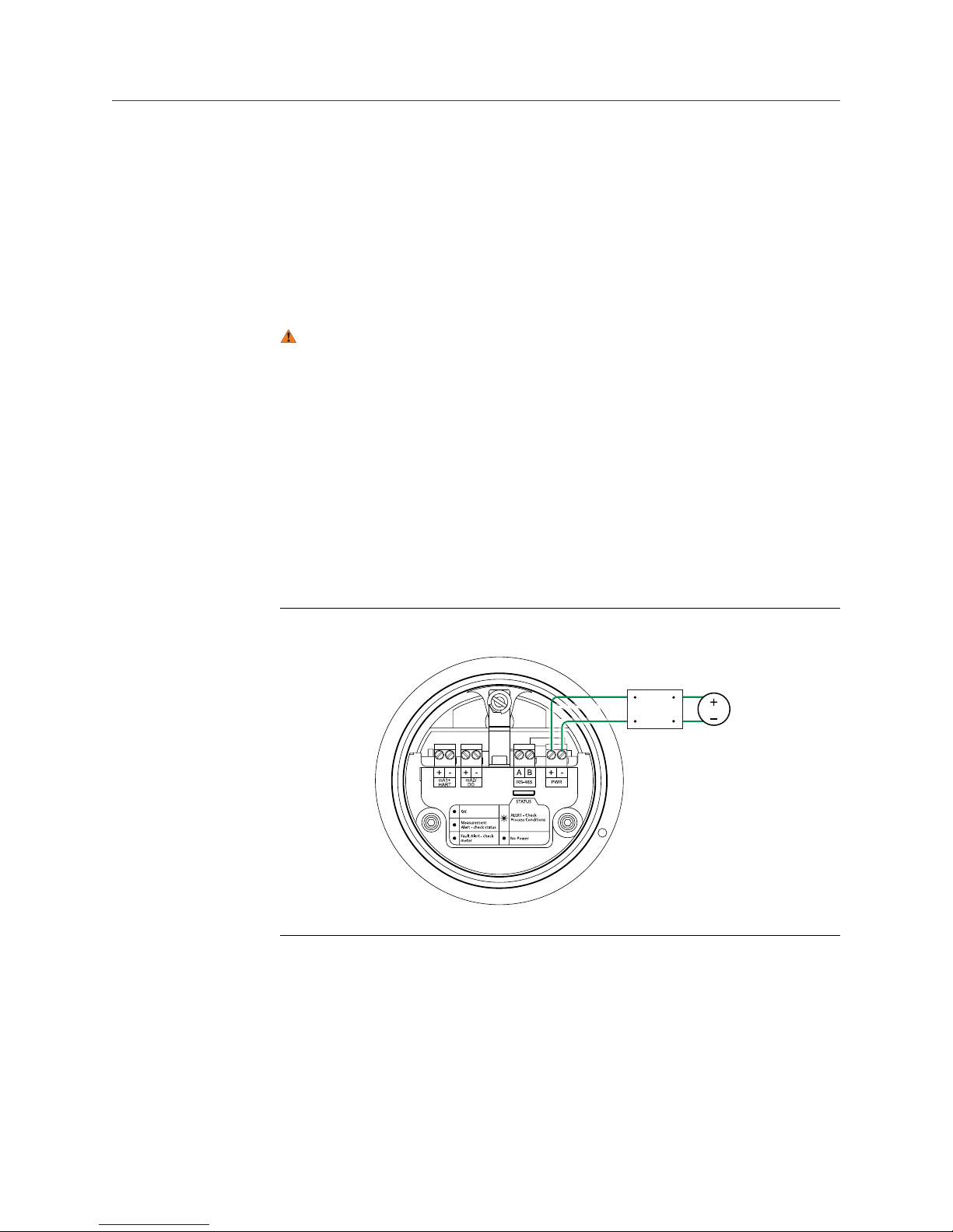
4. Connect the power wiring, and power up the meter.
Planning
Remove the back transmitter housing cover to access the PWR terminals.
Power supply wiring terminalsFigure 1-9:
A. Barrier wiring is applicable to intrinsically safe installations only
5. Perform a Known Density Verification (KDV) check.
Use the Known Density Verification procedure to match the current meter
calibration with the factory calibration. If the meter passes the test, then it has not
drifted or changed during shipment.
For more information on performing a KDV check, see the configuration and use
manual that shipped with the product.
Installation Manual 11
 Loading...