

Page 1
Micro Motion® 4200 Transmitters
Configuration and Use Manual
Configuration and Use Manual
MMI-20048166, Rev AA
April 2019
Page 2

Safety messages
Safety messages are provided throughout this manual to protect personnel and equipment. Read each safety message carefully
before proceeding to the next step.
Other information
Full product specifications can be found in the product data sheet. Troubleshooting information can be found in the configuration
manual. Product data sheets and manuals are available from the Micro Motion web site at www.emerson.com.
Return policy
Follow Micro Motion procedures when returning equipment. These procedures ensure legal compliance with government
transportation agencies and help provide a safe working environment for Micro Motion employees. Micro Motion will not accept
your returned equipment if you fail to follow Micro Motion procedures.
Return procedures and forms are available on our web support site at www.emerson.com, or by phoning the Micro Motion
Customer Service department.
Emerson Flow customer service
Email:
• Worldwide: flow.support@emerson.com
• Asia-Pacific: APflow.support@emerson.com
Telephone:
North and South America Europe and Middle East Asia Pacific
United States 800-522-6277 U.K. 0870 240 1978 Australia 800 158 727
Canada +1 303-527-5200 The Netherlands +31 (0) 704 136
Mexico +41 (0) 41 7686
111
Argentina +54 11 4837 7000 Germany 0800 182 5347 Pakistan 888 550 2682
Brazil +55 15 3413 8000 Italy 8008 77334 China +86 21 2892 9000
France 0800 917 901 India 800 440 1468
Central & Eastern +41 (0) 41 7686
Russia/CIS +7 495 981 9811 South Korea +82 2 3438 4600
Egypt 0800 000 0015 Singapore +65 6 777 8211
Oman 800 70101 Thailand 001 800 441 6426
Qatar 431 0044 Malaysia 800 814 008
Kuwait 663 299 01
South Africa 800 991 390
Saudi Arabia 800 844 9564
UAE 800 0444 0684
666
111
New Zealand 099 128 804
Japan +81 3 5769 6803
2
Page 3

Configuration and Use Manual Contents
MMI-20048166 April 2019
Contents
Chapter 1 Before you begin............................................................................................................7
1.1 About this manual............................................................................................................................ 7
1.2 Related documents.......................................................................................................................... 7
1.3 Installation types.............................................................................................................................. 7
1.4 Communication tools and protocols.................................................................................................9
Chapter 2 Quick start................................................................................................................... 11
2.1 Applying power.............................................................................................................................. 11
2.2 Check meter status.........................................................................................................................11
2.3 Commissioning wizards..................................................................................................................12
2.4 Make a startup connection to the transmitter.................................................................................12
2.5 Set the transmitter clock................................................................................................................ 12
2.6 View the licensed features..............................................................................................................13
2.7 Set informational parameters.........................................................................................................13
2.8 Characterize the meter (if required)................................................................................................14
2.9 Verify mass flow measurement.......................................................................................................17
2.10 Verify the zero.............................................................................................................................. 17
Chapter 3 Introduction to configuration and commissioning........................................................19
3.1 Security and write protection......................................................................................................... 19
3.2 Work with configuration files..........................................................................................................21
Chapter 4 Configure process measurement..................................................................................23
4.1 Configure Sensor Flow Direction Arrow.......................................................................................... 23
4.2 Configure mass flow measurement................................................................................................ 24
4.3 Configure volume flow measurement for liquid applications.......................................................... 28
4.4 Configure Gas Standard Volume (GSV) flow measurement.............................................................32
4.5 Configure density measurement.................................................................................................... 36
4.6 Configure temperature measurement............................................................................................38
4.7 Configure Pressure Measurement Unit .......................................................................................... 40
4.8 Configure Velocity Measurement Unit ........................................................................................... 40
Chapter 5 Configure process measurement applications.............................................................. 43
5.1 Set up the API referral application .................................................................................................. 43
5.2 Set up concentration measurement............................................................................................... 56
Chapter 6 Configure advanced options for process measurement................................................ 69
6.1 Detect and report two-phase flow.................................................................................................. 69
6.2 Configure Flow Rate Switch ........................................................................................................... 70
6.3 Configure events............................................................................................................................ 71
6.4 Configure totalizers and inventories............................................................................................... 73
Configuration and Use Manual 3
Page 4

Contents Configuration and Use Manual
April 2019 MMI-20048166
6.5 Configure logging for totalizers and inventories............................................................................. 76
6.6 Configure Process Variable Fault Action .........................................................................................76
Chapter 7 Configure device options and preferences....................................................................81
7.1 Configure the transmitter display................................................................................................... 81
7.2 Configure the transmitter's response to alerts................................................................................ 85
Chapter 8 Integrate the meter with the control system................................................................ 93
8.1 Configure the transmitter channels................................................................................................ 93
8.2 Configure the mA outputs.............................................................................................................. 94
8.3 Configure the Frequency Output.................................................................................................. 102
8.4 Configure the Discrete Output..................................................................................................... 106
Chapter 9 Configure digital communications............................................................................. 109
9.1 Configure HART communications ................................................................................................109
Chapter 10 Complete the configuration....................................................................................... 115
10.1 Test or tune the system using sensor simulation.........................................................................115
10.2 Enable or disable software write protection................................................................................116
Chapter 11 Transmitter operation................................................................................................119
11.1 View process and diagnostic variables........................................................................................ 119
11.2 View and acknowledge status alerts........................................................................................... 120
11.3 Read totalizer and inventory values............................................................................................ 122
11.4 Start, stop, and reset totalizers and inventories.......................................................................... 122
Chapter 12 Measurement support................................................................................................125
12.1 Use Smart Meter Verification (SMV)........................................................................................... 125
12.2 Zero the meter........................................................................................................................... 132
12.4 Set up pressure compensation................................................................................................... 134
12.5 Validate the meter......................................................................................................................139
12.6 Perform a (standard) D1 and D2 density calibration....................................................................141
Chapter 13 Maintenance..............................................................................................................145
13.1 Install a new transmitter license................................................................................................. 145
13.2 Reboot the transmitter...............................................................................................................146
13.3 Battery replacement...................................................................................................................146
Chapter 14 Log files, history files, and service files........................................................................147
14.1 Generate history log files............................................................................................................147
14.2 Generate service files..................................................................................................................148
14.3 SMV history and SMV log............................................................................................................149
14.4 Totalizer history and log............................................................................................................. 150
14.5 Generate service files..................................................................................................................151
Chapter 15 Troubleshooting........................................................................................................ 157
15.1 Overview.................................................................................................................................... 157
15.2 Status alerts, causes, and recommendations.............................................................................. 157
4 Micro Motion 4200 Transmitters
Page 5

Configuration and Use Manual Contents
MMI-20048166 April 2019
15.3 Transmitter does not communicate........................................................................................... 174
15.4 API referral problems..................................................................................................................174
15.5 Concentration measurement problems......................................................................................175
15.6 Density measurement problems................................................................................................ 176
15.7 Discrete Output problems..........................................................................................................178
15.8 Flow measurement problems..................................................................................................... 179
15.9 Frequency Output problems.......................................................................................................181
15.10 Milliamp output problems........................................................................................................183
15.11 Temperature measurement problems......................................................................................186
15.12 Check power supply wiring.......................................................................................................187
15.13 Check sensor to transmitter wiring...........................................................................................188
15.14 Check grounding......................................................................................................................189
15.15 Perform loop tests....................................................................................................................189
15.16 Trim mA Output....................................................................................................................... 193
15.17 Using sensor simulation for troubleshooting............................................................................ 194
15.18 Check HART communications.................................................................................................. 194
15.19 Check Lower Range Value and Upper Range Value ...................................................................195
15.20 Check mA Output Fault Action .................................................................................................195
15.21 Check the scaling of the frequency output............................................................................... 195
15.22 Check Frequency Output Mode ............................................................................................... 195
15.23 Check Frequency Output Fault Action ......................................................................................196
15.24 Check the direction parameters............................................................................................... 196
15.25 Check the cutoffs..................................................................................................................... 196
15.26 Check for two-phase flow (slug flow)........................................................................................196
15.27 Check for radio frequency interference (RFI).............................................................................197
15.28 Check HART burst mode...........................................................................................................197
15.29 Check the drive gain................................................................................................................. 197
15.30 Checking process variables.......................................................................................................198
15.31 Check the pickoff voltage......................................................................................................... 201
15.32 Check for internal electrical problems...................................................................................... 202
15.33 Locate a device using the HART 7 Squawk feature.................................................................... 203
Appendix A Using the transmitter display..................................................................................... 205
A.1 Components of the transmitter display........................................................................................ 205
A.2 Access and use the display menu..................................................................................................206
Appendix B Using ProLink III with the transmitter......................................................................... 211
B.1 Basic information about ProLink III ...............................................................................................211
B.2 Connect with ProLink III ............................................................................................................... 212
Appendix C Using a Field Communicator with the transmitter...................................................... 215
C.1 Basic information about the Field Communicator ........................................................................215
C.2 Connect with the Field Communicator ........................................................................................ 215
Configuration and Use Manual 5
Page 6

Contents Configuration and Use Manual
April 2019 MMI-20048166
Appendix D Channel combinations................................................................................................217
D.1 Rules for channel combinations................................................................................................... 217
D.2 Valid combinations for channel configuration..............................................................................217
Appendix E Concentration measurement matrices, derived variables, and process variables........ 219
E.1 Standard matrices for the concentration measurement application............................................. 219
E.2 Derived variables and calculated process variables....................................................................... 220
Appendix F Environmental compliance.........................................................................................223
F.1 RoHS and WEEE............................................................................................................................ 223
6 Micro Motion 4200 Transmitters
Page 7

Configuration and Use Manual Before you begin
MMI-20048166 April 2019
1 Before you begin
1.1 About this manual
This manual helps you configure, commission, use, maintain, and troubleshoot Micro Motion 4200
transmitters.
Important
This manual assumes that the following conditions apply:
• The transmitter has been installed correctly and completely according to the instructions in the
transmitter installation manual
• The installation complies with all applicable safety requirements
• The user is trained in government and corporate safety standards
1.2 Related documents
See the approval documentation shipped with the transmitter, or download the appropriate documentation
from the Micro Motion web site (www.emerson.com):
• Micro Motion 4200 2-Wire Transmitter: Installation Manual
• Micro Motion 4200 2-Wire Transmitter: Product Data Sheet
• Micro Motion 4200 2-Wire Transmitter: Safety Manual for Safety Instrumented Systems
• Micro Motion ProLink III User Manual
• Sensor installation manual, which is shipped with the sensor
• FMEDA report for Coriolis Flowmeter with the 4200 Transmitter, Prepared for Emerson by exida.com LLC
1.3 Installation types
The 4200 transmitter was ordered and shipped for one of two installation types. The fifth character of the
transmitter number indicates the installation type.
Figure 1-1: Installation type indication for 4200 transmitters
The number is located on the device tag on the side of the transmitter.
Table 1-1: Installation types for 4200 transmitters
Code Description
I Integral mount
C Remote mount
Configuration and Use Manual 7
Page 8

Before you begin Configuration and Use Manual
April 2019 MMI-20048166
Figure 1-2: 4200 transmitter -- Integral mount
A. Conduit openings
B. Clamping ring
C. Sensor case
D. Transmitter housing cover (hidden from view)
The transmitter is installed directly on the sensor.
The connections between the transmitter and sensor are 9-wire, and do not require field wiring on the
integral mount version.
The I/O connections consist of 2 channels, each channel being 2-wire. Power must be supplied to Channel A
for the transmitter to operate, while Channel B connections are optional.
8 Micro Motion 4200 Transmitters
Page 9

Configuration and Use Manual Before you begin
MMI-20048166 April 2019
Figure 1-3: 4200 transmitter -- Remote mount
A. Transmitter housing cover
B. Clamping ring
C. Junction box
The transmitter is installed remotely from the sensor. The 9-wire connection between the sensor and
transmitter must be field wired. Power supply and I/O must be field wired to the transmitter. The sensor
connection is in the junction box.
1.4 Communication tools and protocols
You can use several different communications tools and protocols to interface with the transmitter, use
different tools in different locations, or use different tools for different tasks.
Tool
Display Not applicable
ProLink III • HART
Field Communicator • HART
For information about how to use the communication tools, see Using ProLink III with the transmitter and
Using a Field Communicator with the transmitter in this manual.
Supported protocols
• "Factory Use Only" port in non-hazardous areas
Configuration and Use Manual 9
Page 10

Before you begin Configuration and Use Manual
April 2019 MMI-20048166
Note
Some configuration and administrative procedures can also be performed through the display menus.
However, for complete access to transmitter functions, Micro Motion recommends setting up and using an
administrative connection.
Tip
You may be able to use other communications tools, such as AMS Suite: Intelligent Device Manager, or the
Smart Wireless THUM™ Adapter. Use of AMS or the Smart Wireless THUM Adapter is not discussed in this
manual. For more information on the Smart Wireless THUM Adapter, refer to the documentation available at
www.emerson.com.
10 Micro Motion 4200 Transmitters
Page 11

Configuration and Use Manual Quick start
MMI-20048166 April 2019
2 Quick start
2.1 Applying power
The transmitter must be powered up for all configuration and commissioning tasks, or for process
measurement.
Procedure
1. Verify that the cables are connected to the transmitter as described in the installation manual.
2. Verify that all transmitter and sensor covers and seals are closed.
WARNING
To prevent ignition of flammable or combustible atmospheres, ensure that all covers and seals are
tightly closed. For hazardous area installations, applying power while housing covers are removed or
loose can cause an explosion.
3. Turn on the electrical power at the power supply.
The transmitter will automatically perform diagnostic routines. During this period, the Transmitter
Initializing alert is active. The diagnostic routines should complete in approximately 30 seconds.
Postrequisites
Although the sensor is ready to receive process fluid shortly after power-up, the electronics can take up to
10 minutes to reach thermal equilibrium. Therefore, if this is the initial startup, or if power has been off long
enough to allow components to reach ambient temperature, allow the electronics to warm up for
approximately 10 minutes before relying on process measurements. During this warm-up period, you may
observe minor measurement instability or inaccuracy.
When the flowmeter has completed its power-up sequence, if the default settings are in effect:
• The display will show the current mass flow rate and measurement unit.
• If there are any active fault or informational alarms, the alert banner displays until the alert has been
manually acknowledged.
• If the alert has been acknowledged but is still active, the alert icon displays above the menu button, and
the Alert List menu appears at the top of the main menu.
2.2 Check meter status
Check the meter for any error conditions that require user action or that affect measurement accuracy.
Procedure
Wait approximately 10 seconds for the power-up sequence to complete.
Immediately after power-up, the transmitter runs through diagnostic routines and checks for error
conditions. During the power-up sequence, the Transmitter Initializing alert is active. This alert
should clear automatically when the power-up sequence is complete.
Configuration and Use Manual 11
Page 12

Quick start Configuration and Use Manual
April 2019 MMI-20048166
2.3 Commissioning wizards
The transmitter menu includes a Guided Setup to help you move quickly through the most common
configuration parameters. ProLink III also provides a commissioning wizard.
By default, when the transmitter starts up, the Guided Setup menu is offered. You can choose to use it or not.
You can also choose whether or not Guided Setup is displayed automatically.
• To enter Guided Setup upon transmitter startup, choose Yes at the prompt.
• To enter Guided Setup after transmitter startup, choose Menu > Startup Tasks.
• To control the automatic display of Guided Setup, choose Menu > Configuration > Guided Setup.
For information on the ProLink III commissioning wizard, see the Micro Motion ProLink III User Manual.
As the commissioning wizards are self guided, they are not documented in detail.
2.4 Make a startup connection to the transmitter
For all configuration tools except the display, you must have an active connection to the transmitter to
configure the transmitter.
Procedure
Identify the connection type to use, and follow the instructions for that connection type in the appropriate
appendix.
Communications tool
ProLink III HART Using ProLink III with the transmitter
Field Communicator HART Using a Field Communicator with the
Connection type to use Instructions
transmitter
2.5 Set the transmitter clock
Display
ProLink III Device Tools > Configuration > Transmitter Clock
Field Communicator Configure > Manual Setup > Clock
The transmitter clock provides timestamp data for alerts, service logs, history logs, and all other timers and
dates in the system. You can set the clock for your local time or for any standard time you want to use.
Tip
You may find it convenient to set all of your transmitter clocks to the same time, even if the transmitters are
in different time zones.
Menu > Configuration > Time/Date/Tag
Procedure
1. Select the time zone that you want to use.
2. If you need a custom time zone, select Special Time Zone and enter your time zone as a difference
from UTC (Coordinated Universal Time).
3. Set the time appropriately for the selected time zone.
12 Micro Motion 4200 Transmitters
Page 13

Configuration and Use Manual Quick start
MMI-20048166 April 2019
Tip
The transmitter does not adjust for Daylight Savings Time. If you observe Daylight Savings Time, you
must reset the transmitter clock manually.
4. Set the month, day, and year.
The transmitter tracks the year and automatically adds a day for leap years.
2.6 View the licensed features
Display Menu > About > Licenses > Licensed Features
ProLink III Device Tools > Device Information > Licensed Features
Field Communicator Overview > Device Information > Licenses
You can view the licensed features to ensure that the transmitter was ordered with the required features.
Licensed features are purchased and available for permanent use. The options model code represents the
licensed features.
A trial license allows you to explore features before purchasing. The trial license enables the specified features
for a limited number of days. This number is displayed for reference. At the end of this period, the feature will
no longer be available.
To purchase additional features or request a trial license, document the Unique ID Number and current
license key from your transmitter and contact customer service. To enable the additional features or trial
license, you will need to install the new license on the transmitter.
2.7 Set informational parameters
Display
ProLink III Device Tools > Configuration > Informational Parameters
Field Communicator Configure > Manual Setup > Device
You can set several parameters that identify or describe the transmitter and sensor. These parameters are not
used in processing and are not required.
Procedure
1. Set informational parameters for the transmitter.
a) Set Transmitter Serial Number to the serial number of your transmitter.
The transmitter serial number is provided on the metal tag that is attached to the transmitter
housing.
Menu > Configuration > Device Information
b) Set Descriptor to any desired description of this transmitter or measurement point.
c) Set Message to any desired message.
d) Verify that Model Code (Base) is set to the base model code of the transmitter.
Configuration and Use Manual 13
Page 14

Quick start Configuration and Use Manual
April 2019 MMI-20048166
The base model code completely describes your transmitter, except for the features that can be
licensed independently. The base model code is set at the factory.
e) Set Model Code (Options) to the options model code of the transmitter.
The options model code describes the independent features that have been licensed for this
transmitter. The original options model code is set at the factory. If you license additional
options for this transmitter, Micro Motion will supply an updated options model code.
2. Set informational parameters for the sensor.
a) Set Sensor Serial Number to the serial number of the sensor connected to this transmitter.
The sensor serial number is provided on the metal tag that is attached to the sensor case.
b) Set Sensor Material to the material used for the sensor.
c) Set Sensor Liner to the material used for the sensor liner.
d) Set Flange Type to the type of flange that was used to install the sensor.
Do not set Sensor Type. Sensor Type is set or derived during characterization.
2.8 Characterize the meter (if required)
Display
ProLink III Device Tools > Calibration Data
Field Communicator Configure > Manual Setup > Characterization
Characterizing the meter adjusts your transmitter to match the unique traits of the sensor it is paired with.
The characterization parameters (also called calibration parameters) describe the sensor’s sensitivity to flow,
density, and temperature. Depending on your sensor type, different parameters are required.
Values for your sensor are provided on the sensor tag or the calibration certificate.
• If your transmitter was ordered with a sensor, it was characterized at the factory. However, you should still
verify the characterization parameters.
• Perform a characterization whenever you replace a core processor.
Procedure
1. Optional: Specify Sensor Type as Curved Tube.
Note
Unlike earlier transmitters, the 4200 derives Sensor Type from the user-specified values for FCF and K1
in combination with an internal ID.
2. Set the flow calibration factor: FCF (also called Flow Cal or Flow Calibration Factor). Be sure to include
all decimal points.
3. Set the density characterization parameters: D1, D2, TC, K1, K2, and FD. (TC is sometimes shown as
DT.)
4. Apply the changes as required by the tool you are using.
Menu > Configuration > Sensor Parameters
14 Micro Motion 4200 Transmitters
Page 15

Configuration and Use Manual Quick start
MMI-20048166 April 2019
The transmitter identifies your sensor type, and characterization parameters are adjusted as required:
• If Sensor Type changed from Straight Tube to Curved Tube, five characterization parameters are
removed from the list.
• If Sensor Type did not change, the list of characterization parameters does not change.
2.8.1 Sample sensor tags
Figure 2-1: Tag on older curved-tube sensors (all sensors except T-Series)
Figure 2-2: Tag on newer curved-tube sensors (all sensors except T-Series)
Configuration and Use Manual 15
Page 16

Quick start Configuration and Use Manual
April 2019 MMI-20048166
2.8.2 Flow calibration parameters (FCF, FT)
Two separate values are used to describe flow calibration: a 6-character FCF value and a 4-character FT value.
They are provided on the sensor tag.
Both values contain decimal points. During characterization, these are entered as a single 10-character string.
The 10-character string is called either Flowcal or FCF.
If your sensor tag shows the FCF and the FT values separately and you need to enter a single value,
concatenate the two values to form the single parameter value, retaining both decimal points.
Concatenating FCF and FT
FCF = x.xxxx FT = y.yy Flow calibration parameter: x.xxxxy.yy
2.8.3 Density calibration parameters (D1, D2, K1, K2, FD, DT, TC)
Density calibration parameters are typically on the sensor tag and the calibration certificate.
If your sensor tag does not show a D1 or D2 value:
• For D1, enter the Dens A or D1 value from the calibration certificate. This value is the line-condition
density of the low-density calibration fluid. Micro Motion uses air. If you cannot find a Dens A or D1 value,
enter 0.001 g/cm3.
• For D2, enter the Dens B or D2 value from the calibration certificate. This value is the line-condition density
of the high-density calibration fluid. Micro Motion uses water. If you cannot find a Dens B or D2 value,
enter 0.998g/cm3 .
If your sensor tag does not show a K1 or K2 value:
• For K1, enter the first 5 digits of the density calibration factor. In this sample tag, this value is shown as
12500.
• For K2, enter the second 5 digits of the density calibration factor. In this sample tag, this value is shown as
14286.
Figure 2-3: K1, K2, and TC values in the density calibration factor
16 Micro Motion 4200 Transmitters
Page 17

Configuration and Use Manual Quick start
MMI-20048166 April 2019
If your sensor does not show an FD value, contact customer service.
If your sensor tag does not show a DT or TC value, enter the last 4 characters of the density calibration factor.
In the sample tag shown above, the value is shown as 4.44.
2.9 Verify mass flow measurement
Check to see that the mass flow rate reported by the transmitter is accurate. You can use any available
method.
Procedure
• Read the value for Mass Flow Rate on the transmitter display, which is the default initial display.
• Connect to the transmitter with ProLink III and read the value for Mass Flow Rate in the Process Variables
panel.
• Connect to the transmitter with the Field Communicator and read the value for Mass Flow Rate.
Online > Overview > Mass Flow Rate
Postrequisites
If the reported mass flow rate is not accurate:
• Check the characterization parameters.
• Review the troubleshooting suggestions for flow measurement issues.
2.10 Verify the zero
Display
ProLink III Device Tools > Calibration > Smart Zero Verification and Calibration > Verify Zero
Field Communicator Service Tools > Maintenance > Calibration > Zero Calibration > Perform Zero Verify
Verifying the zero helps you determine if the stored zero value is appropriate to your installation, or if a field
zero can improve measurement accuracy.
Important
In most cases, the factory zero is more accurate than the field zero. Do not zero the meter unless one of the
following is true:
• The zero is required by site procedures.
• The stored zero value fails the zero verification procedure.
Prerequisites
Important
Do not verify the zero or zero the meter if a high-severity alert is active. Correct the problem, then verify the
zero or zero the meter. You may verify the zero or zero the meter if a low-severity alert is active.
Menu > Service Tools > Verification & Calibration > Meter Zero > Zero Verification
Procedure
1. Prepare the meter:
Configuration and Use Manual 17
Page 18

Quick start Configuration and Use Manual
April 2019 MMI-20048166
a) Allow the meter to warm up for at least 20 minutes after applying power.
b) Run the process fluid through the sensor until the sensor temperature reaches the normal
process operating temperature.
c) Stop flow through the sensor by shutting the downstream valve, and then the upstream valve if
available.
d) Verify that the sensor is blocked in, that flow has stopped, and that the sensor is completely full
of process fluid.
2. Start the zero verification procedure, and wait until it completes.
3. If the zero verification procedure fails:
a) Confirm that the sensor is completely blocked in, that flow has stopped, and that the sensor is
completely full of process fluid.
b) Verify that the process fluid is not flashing or condensing, and that it does not contain particles
that can settle out.
c) Repeat the zero verification procedure.
d) If it fails again, zero the meter.
Postrequisites
Restore normal flow through the sensor by opening the valves.
Related information
Zero the meter
18 Micro Motion 4200 Transmitters
Page 19
Configuration and Use Manual Introduction to configuration and commissioning
MMI-20048166 April 2019
3 Introduction to configuration and commissioning
3.1 Security and write protection
The transmitter has several features that can help to protect it against intentional or unintentional access and
configuration changes.
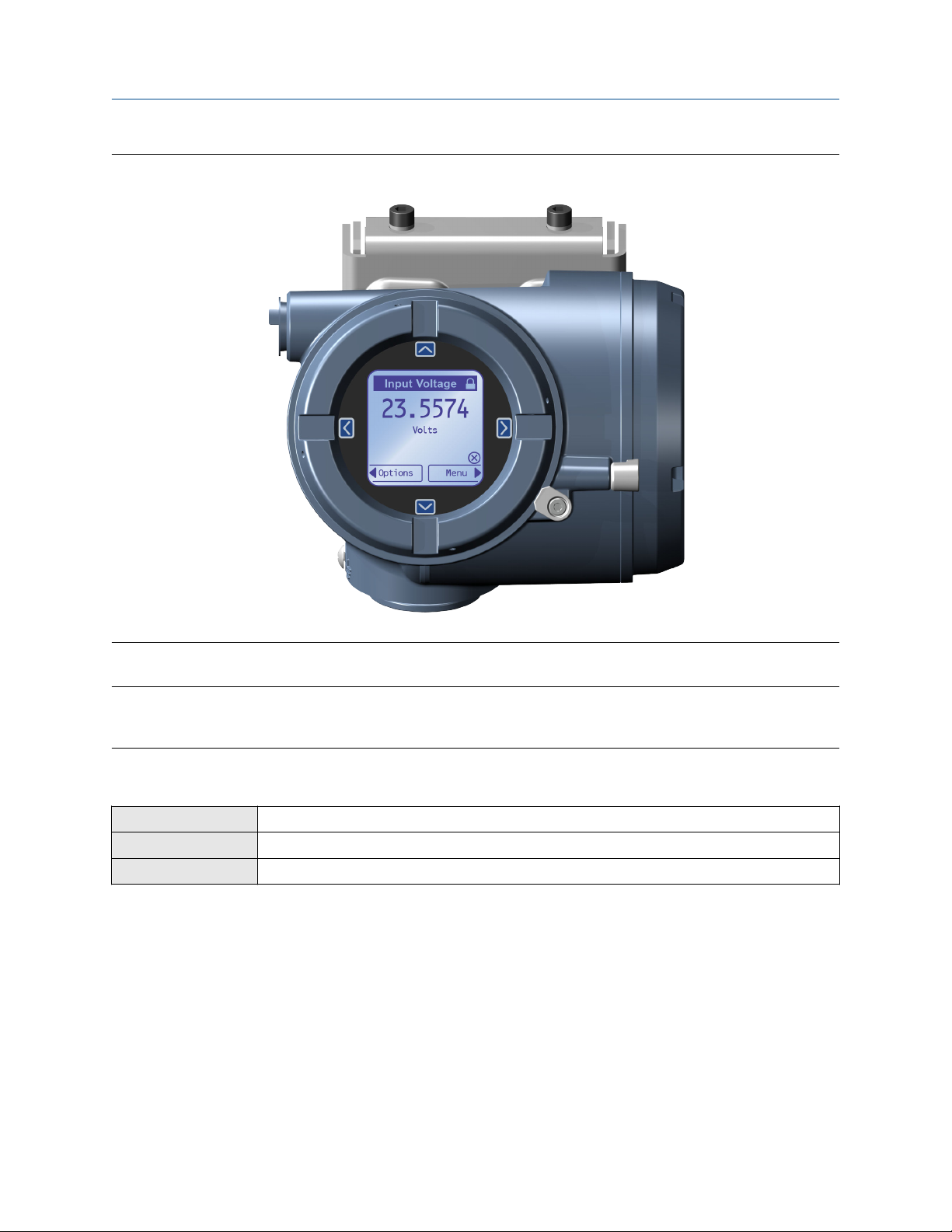
• When enabled, the software setting Write Protection prevents any configuration changes. When
enabled, a lock icon displays at the top of the home screen of the display.
• When enabled, the display option Display Security prevents any configuration changes being made from
the display unless the display password is entered. Display Security does not prevent configuration
changes from other interfaces.
3.1.1 Enable or disable software write protection
When enabled, Write-Protection prevents changes to the transmitter configuration. You can perform all
other functions, and you can view the transmitter configuration parameters.
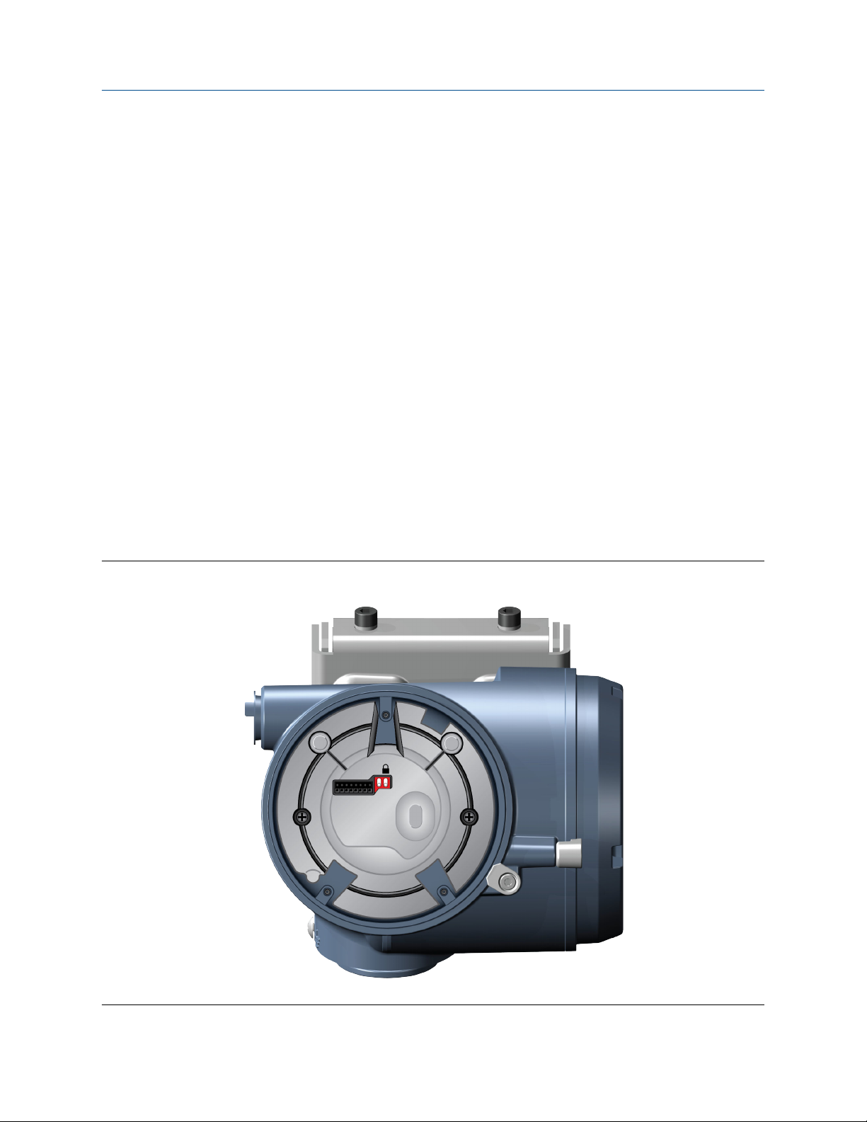
Write protection is enabled by toggling the physical write protect (dip) switch (identified by a lock icon)
located behind the display module.
Figure 3-1: Write Protect (Dip) Switch Behind the Display Module
Configuration and Use Manual 19
Page 20
Introduction to configuration and commissioning Configuration and Use Manual
April 2019 MMI-20048166
Figure 3-2: Write Protect on the Display (Upper Right Corner)
You cannot change write protection from any host configuration tool.
Note
Write protecting the transmitter primarily prevents accidental changes to configuration, not intentional
changes. Any user who can make changes to the configuration can disable write protection.
3.1.2 Configure security for the display
Display
ProLink III Device Tools > Configuration > Transmitter Display > Display Security
Field Communicator Configure > Manual Setup > Display > Display Menus
You can configure a display password, and require the operator to enter the password to make any changes
to configuration through the display, or to access alert data through the display.
The operator always has read-only access to the configuration menus.
Procedure
1. Enable or disable display security as desired.
Menu > Configuration > Security > Display Security
20 Micro Motion 4200 Transmitters
Page 21

Configuration and Use Manual Introduction to configuration and commissioning
MMI-20048166 April 2019
Option Description
Enabled When an operator chooses an action that leads to a configuration change, they are
prompted to enter the display password.
Disabled When an operator chooses an action that leads to a configuration change, they are
prompted to activate ⇦⇧⇩⇨. This is designed to protect against accidental changes to
configuration. It is not a security measure.
2. If you enabled display security, enable or disable alert security as desired.
Option Description
Enabled If an alert is active, the alert symbol ⓘ is shown above the Menu button on the display but
the alert banner is not displayed. If the operator attempts to enter the alert menu, they are
prompted to enter the display password.
Disabled If an alert is active, the alert symbol ⓘ is shown in the upper right corner of the display and
the alert banner is displayed automatically. No password or confirmation is required to
enter the alert menu.
Restriction
You cannot disable display security and enable alert security.
• If you did not enable display security, alert security is disabled and cannot be enabled.
• If both display security and alert security are enabled, and you disable display security, alert security
is disabled automatically.
3. Set the display password to the desired value.
• Default: AAAA
• Range: Any four alphanumeric characters
If you enable display security but you do not change the display password, the transmitter will post a
Configuration alert.
3.2 Work with configuration files
3.2.1 Save a configuration file using ProLink III
You can save the current transmitter configuration to your PC. The ProLink PC file format is supported.
Procedure
• To save the current configuration to your PC, in ProLink III format:
a) Choose Device Tools > Configuration Transfer > Save Configuration.
b) Select On my computer in ProLink III file format and click Next.
c) Click Save.
d) Select the configuration parameters to be included in this file.
Configuration and Use Manual 21
Page 22

Introduction to configuration and commissioning Configuration and Use Manual
April 2019 MMI-20048166
— To save a backup file, select all parameters.
— To save a replication file, select all parameters except device-specific parameters.
e) Click Save.
f) Browse to the desired location, then enter the name for this configuration file.
g) Set the file type to ProLink configuration file.
h) Click Start Save.
The configuration file is saved to the specified location as yourname.pcfg.
3.2.2 Load a configuration file using ProLink III
You can load a configuration file to the transmitter's working memory. The PC file formats are supported: the
ProLink III PC file format is supported.
Note
When you use ProLink III format for configuration files, you can specify configuration parameters individually
or by groups. Therefore, you can use this format for both backup and replication.
Procedure
• To load a file in ProLink III format from the PC:
a) Choose Device Tools > Configuration Transfer > Load Configuration.
b) Select On my computer in ProLink III file format and click Next.
c) Select the parameters that you want to load.
d) Click Load.
e) Set the file type to Configuration file.
f) Navigate to the file you want to load, and select it.
g) Click Start Load.
The parameters are written to working memory, and the new settings become effectively immediately.
3.2.3 Restore the factory configuration
Display
ProLink III Device Tools > Configuration Transfer > Restore Factory Configuration
Field Communicator Service Tools > Maintenance > Reset/Restore > Restore Factory Configuration
A file containing the factory configuration is always saved in the transmitter's internal memory, and is
available for use.
Menu > Configuration > Restore Factory Configuration
This action is typically used for error recovery or for repurposing a transmitter.
If you restore the factory configuration, the real-time clock, the audit trail, the historian, and other logs are
not reset.
22 Micro Motion 4200 Transmitters
Page 23
Configuration and Use Manual Configure process measurement
MMI-20048166 April 2019
4 Configure process measurement
4.1 Configure Sensor Flow Direction Arrow
Display Menu > Configuration > Process Measurement > Flow Variables > Flow Direction
ProLink III Device Tools > Configuration > Process Measurement > Flow
Field Communicator Configure > Manual Setup > Measurements > Flow > Sensor Direction
Sensor Flow Direction Arrow is used to accommodate installations in which the Flow arrow on the sensor
does not match the majority of the process flow. This typically happens when the sensor is accidentally
installed backwards.
Sensor Flow Direction Arrow interacts with mA Output Direction, Frequency Output Direction, and
Totalizer Direction to control how flow is reported by the outputs and accumulated by the totalizers and
inventories.
Sensor Flow Direction Arrow also affects how flow is reported on the transmitter display and via digital
communications. This includes ProLink III and the Field Communicator.
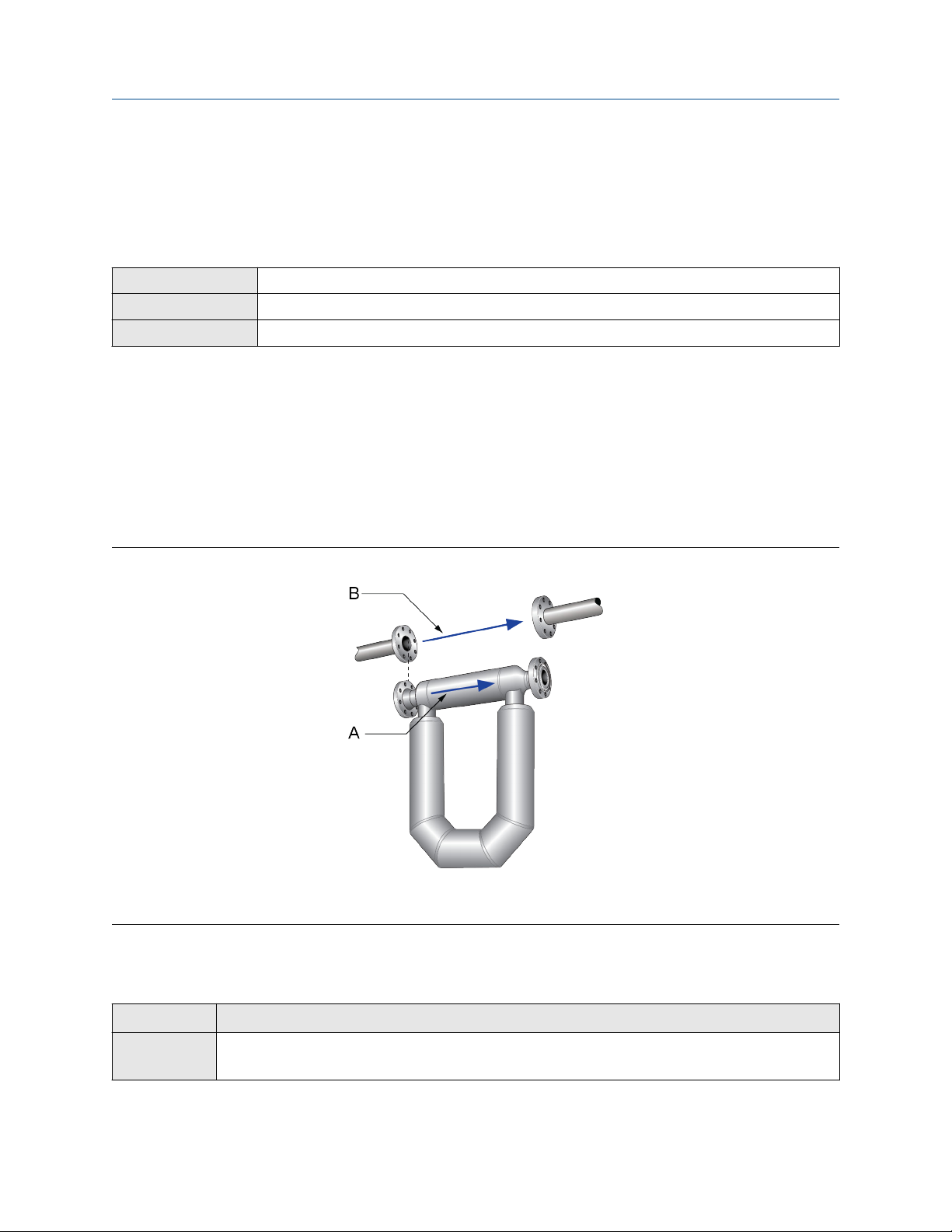
Figure 4-1: Flow arrow on sensor
A. Flow arrow
B. Actual flow direction
Procedure
Set Sensor Flow Direction Arrow as appropriate.
Option
With Arrow The majority of flow through the sensor matches the flow arrow on the sensor. Actual
Configuration and Use Manual 23
Description
forward flow is processed as forward flow.
Page 24

Configure process measurement Configuration and Use Manual
April 2019 MMI-20048166
Option Description
Against Arrow The majority of flow through the sensor is opposite to the flow arrow on the sensor. Actual
forward flow is processed as reverse flow.
Tip
Micro Motion sensors are bidirectional. Measurement accuracy is not affected by actual flow direction or the
setting of Sensor Flow Direction Arrow. Sensor Flow Direction Arrow controls only whether actual flow is
processed as forward flow or reverse flow
4.2 Configure mass flow measurement
The mass flow measurement parameters control how mass flow is measured and reported. The mass total
and mass inventory are derived from the mass flow data.
4.2.1 Configure Mass Flow Measurement Unit
Display Menu > Configuration > Process Measurement > Flow Variables > Mass Flow Settings > Units
ProLink III Device Tools > Configuration > Process Measurement > Flow > Mass Flow Rate Unit
Field Communicator Configure > Manual Setup > Measurements > Flow > Mass Flow Unit
Mass Flow Measurement Unit specifies the unit of measure that will be used for the mass flow rate. The
default unit used for mass total and mass inventory is derived from this unit.
Procedure
Set Mass Flow Measurement Unit to the unit you want to use.
• Default: g/sec (grams per second)
Tip
If the measurement unit you want to use is not available, you can define a special measurement unit.
Options for Mass Flow Measurement Unit
The transmitter provides a standard set of measurement units for Mass Flow Measurement Unit, plus one
user-defined special measurement unit. Different communications tools may use different labels for the
units.
Define a special measurement unit for mass flow
Display
ProLink III Device Tools > Configuration > Process Measurement > Flow > Mass Flow Rate Unit > Special
Field Communicator Configure > Manual Setup > Measurements > Optional Setup > Special Units > Mass Special Units
Menu > Configuration > Process Measurement > Flow Variables > Mass Flow Settings > Units > SPECIAL
24 Micro Motion 4200 Transmitters
Page 25

Configuration and Use Manual Configure process measurement
MMI-20048166 April 2019
A special measurement unit is a user-defined unit of measure that allows you to report process data, totalizer
data, and inventory data in a unit that is not available in the transmitter. A special measurement unit is
calculated from an existing measurement unit using a conversion factor.
Procedure
1. Specify Base Mass Unit.
Base Mass Unit is the existing mass unit that the special unit will be based on.
2. Specify Base Time Unit.
Base Time Unit is the existing time unit that the special unit will be based on.
3. Calculate Mass Flow Conversion Factor as follows:
a) x base units = y special units
b) Mass Flow Conversion Factor = x ÷ y
4. Enter Mass Flow Conversion Factor.
The original mass flow rate value is divided by this value.
5. Set Mass Flow Label to the name you want to use for the mass flow unit.
6. Set Mass Total Label to the name you want to use for the mass total and mass inventory unit.
The special measurement unit is stored in the transmitter. You can configure the transmitter to use the
special measurement unit at any time.
Defining a special measurement unit for mass flow
You want to measure mass flow in ounces per second (oz/sec).
1. Set Base Mass Unit to Pounds (lb).
2. Set Base Time Unit to Seconds (sec).
3. Calculate Mass Flow Conversion Factor:
a. 1 lb/sec = 16 oz/sec
b. Mass Flow Conversion Factor = 1 ÷ 16 = 0.0625
4. Set Mass Flow Conversion Factor to 0.0625.
5. Set Mass Flow Label to oz/sec.
6. Set Mass Total Label to oz.
4.2.2 Configure Flow Damping
Display
ProLink III Device Tools > Configuration > Process Measurement > Flow > Flow Rate Damping
Field Communicator Configure > Manual Setup > Measurements > Flow > Flow Damping
Configuration and Use Manual 25
Menu > Configuration > Process Measurement > Flow Variables > Flow Damping
Page 26

Configure process measurement Configuration and Use Manual
April 2019 MMI-20048166
Flow Damping controls the amount of damping that will be applied to the measured mass flow rate. It affects
flow rate process variables that are based on the measured mass flow rate. This includes volume flow rate and
gas standard volume flow rate.
Flow Damping also affects specialized flow rate variables such as temperature-corrected volume flow rate
(API referral) and net mass flow rate (concentration measurement). It is not applied to the flow rate received
via the frequency input.
Damping is used to smooth out small, rapid fluctuations in process measurement. The damping value
specifies the time period, in seconds, over which the transmitter will spread changes in the process variable.
At the end of the interval, the internal value of the process variable (the damped value) will reflect 63% of the
change in the actual measured value.
Procedure
Set Flow Damping to the value you want to use.
• Default: 0.64 seconds
• Range: 0 seconds to 60 seconds
Note
If a number greater than 60 is entered, it is automatically changed to 60.
Tip
• A high damping value makes the process variable appear smoother because the reported value changes
slowly.
• A low damping value makes the process variable appear more erratic because the reported value changes
more quickly.
• The combination of a high damping value and rapid, large changes in flow rate can result in increased
measurement error.
• Whenever the damping value is non-zero, the reported measurement will lag the actual measurement
because the reported value is being averaged over time.
• In general, lower damping values are preferable because there is less chance of data loss, and less lag time
between the actual measurement and the reported value.
• The transmitter automatically rounds off any entered damping value to the nearest valid value. Therefore,
the recommended damping value for gas applications should be 3.2 seconds. If you enter 2.56, the
transmitter will round it off to 3.2.
• For filling applications, Micro Motion recommends using the default value of 0.04 seconds.
26 Micro Motion 4200 Transmitters
Page 27

Configuration and Use Manual Configure process measurement
MMI-20048166 April 2019
Effect of flow damping on volume measurement
Flow damping affects volume measurement for liquid volume data. Flow damping also affects volume
measurement for gas standard volume data. The transmitter calculates volume data from the damped mass
flow data.
Interaction between Flow Damping and mA Output Damping
In some circumstances, both Flow Damping and mA Output Damping are applied to the reported mass flow
value.
Flow Damping controls the rate of change in flow process variables. mA Output Damping controls the rate
of change reported via the mA Output. If mA Output Process Variable is set to Mass Flow Rate, and both
Flow Damping and mA Output Damping are set to non-zero values, flow damping is applied first, and the
added damping calculation is applied to the result of the first calculation.
4.2.3 Configure Mass Flow Cutoff
Display Menu > Configuration > Process Measurement > Flow Variables > Mass Flow Settings > Low Flow Cutoff
ProLink III Device Tools > Configuration > Process Measurement > Flow > Mass Flow Cutoff
Field Communicator Configure > Manual Setup > Measurements > Flow > Mass Flow Cutoff
Mass Flow Cutoff specifies the lowest mass flow rate that will be reported as measured. All mass flow rates
below this cutoff will be reported as 0.
Procedure
Set Mass Flow Cutoff to the value you want to use.
• Default: A sensor-specific value set at the factory. If your transmitter was ordered without a sensor, the
default may be 0.0.
• Recommendation: 0.5% of maximum flow rate of the attached sensor. See the sensor specifications.
Important
Do not use your meter for measurement with Mass Flow Cutoff set to 0.0 g/sec. Ensure that Mass Flow
Cutoff is set to the value that is appropriate for your sensor.
Effect of Mass Flow Cutoff on volume measurement
Mass Flow Cutoff does not affect volume measurement. Volume data is calculated from the actual mass data
rather than the reported value.
Volume flow has a separate Volume Flow Cutoff that is not affected by the Mass Flow Cutoff value.
Interaction between Mass Flow Cutoff and mA Output Cutoff
Mass Flow Cutoff defines the lowest mass flow value that the transmitter will report as measured. mA
Output Cutoff defines the lowest flow rate that will be reported via the mA Output. If mA Output Process
Configuration and Use Manual 27
Page 28

Configure process measurement Configuration and Use Manual
April 2019 MMI-20048166
Variable is set to Mass Flow Rate, the mass flow rate reported via the mA Output is controlled by the higher of
the two cutoff values.
Mass Flow Cutoff affects all reported values and values used in other transmitter behavior (e.g., events
defined on mass flow).
mA Output Cutoff affects only mass flow values reported via the mA Output.
Cutoff interaction with mA Output Cutoff lower than Mass Flow Cutoff
Configuration:
• mA Output Process Variable: Mass Flow Rate
• Frequency Output Process Variable: Mass Flow Rate
• mA Output Cutoff: 10 g/sec
• Mass Flow Cutoff: 15 g/sec
Result: If the mass flow rate drops below 15 g/sec, mass flow will be reported as 0, and 0 will be used in all
internal processing.
Cutoff interaction with mA Output Cutoff higher than Mass Flow Cutoff
Configuration:
• mA Output Process Variable: Mass Flow Rate
• Frequency Output Process Variable: Mass Flow Rate
• mA Output Cutoff: 15 g/sec
• Mass Flow Cutoff: 10 g/sec
Result:
• If the mass flow rate drops below 15 g/sec but not below 10 g/sec:
— The mA Output will report zero flow.
— The Frequency Output will report the actual flow rate, and the actual flow rate will be used in all
internal processing.
• If the mass flow rate drops below 10 g/sec, both outputs will report zero flow, and 0 will be used in all
internal processing.
4.3 Configure volume flow measurement for liquid
applications
The volume flow measurement parameters control how liquid volume flow is measured and reported. The
volume total and volume inventory are derived from volume flow data.
Restriction
You cannot implement both liquid volume flow and gas standard volume flow at the same time. Choose one
or the other.
Related information
Configure Volume Flow Type for liquid applications
28 Micro Motion 4200 Transmitters
Page 29

Configuration and Use Manual Configure process measurement
MMI-20048166 April 2019
Configure Volume Flow Measurement Unit for liquid applications
Configure Volume Flow Cutoff
4.3.1 Configure Volume Flow Type for liquid applications
Display Menu > Configuration > Process Measurement > Flow Variables > Volume Flow Settings > Flow Type >
ProLink III Device Tools > Configuration > Process Measurement > Flow > Volume Flow Type > Liquid Volume
Field Communicator Configure > Manual Setup > Measurements > Optional Setup > GSV > Volume Flow Type > Liquid Volume
Volume Flow Type controls whether liquid or gas standard volume flow measurement will be used.
Restriction
If you are using the API referral application, you must set Volume Flow Type to Liquid. Gas standard volume
measurement is incompatible with the API referral application.
Restriction
If you are using the concentration measurement application, you must set Volume Flow Type to Liquid.
Gas standard volume measurement is incompatible with the following applications:
• Concentration measurement
Procedure
Set Volume Flow Type to Liquid.
Liquid
4.3.2 Configure Volume Flow Measurement Unit for liquid
applications
Display
ProLink III Device Tools > Configuration > Process Measurement > Flow > Volume Flow Rate Unit
Field Communicator Configure > Manual Setup > Measurements > Flow > Volume Flow Unit
Volume Flow Measurement Unit specifies the unit of measurement that will be displayed for the volume
flow rate. The unit used for the volume total and volume inventory is based on this unit.
Prerequisites
Before you configure Volume Flow Measurement Unit, be sure that Volume Flow Type is set to Liquid.
Procedure
Set Volume Flow Measurement Unit to the unit you want to use.
• Default: l/sec (liters per second)
Tip
If the measurement unit you want to use is not available, you can define a special measurement unit.
Configuration and Use Manual 29
Menu > Configuration > Process Measurement > Flow Variables > Volume Flow Settings > Units
Page 30

Configure process measurement Configuration and Use Manual
April 2019 MMI-20048166
Options for Volume Flow Measurement Unit for liquid applications
The transmitter provides a standard set of measurement units for Volume Flow Measurement Unit, plus one
user-defined measurement unit. Different communications tools may use different labels for the units.
Define a special measurement unit for volume flow
Display Menu > Configuration > Process Measurement > Flow Variables > Volume Flow Settings > Units >
ProLink III Device Tools > Configuration > Process Measurement > Flow > Volume Flow Rate Unit > Special
Field Communicator Configure > Manual Setup > Measurements > Optional Setup > Special Units > Volume Special Units
SPECIAL
A special measurement unit is a user-defined unit of measure that allows you to report process data, totalizer
data, and inventory data in a unit that is not available in the transmitter. A special measurement unit is
calculated from an existing measurement unit using a conversion factor.
Procedure
1. Specify Base Volume Unit.
Base Volume Unit is the existing volume unit that the special unit will be based on.
2. Specify Base Time Unit.
Base Time Unit is the existing time unit that the special unit will be based on.
3. Calculate Volume Flow Conversion Factor as follows:
a) x base units = y special units
b) Volume Flow Conversion Factor = x ÷ y
4. Enter Volume Flow Conversion Factor.
The original volume flow rate value is divided by this conversion factor.
5. Set Volume Flow Label to the name you want to use for the volume flow unit.
6. Set Volume Total Label to the name you want to use for the volume total and volume inventory unit.
The special measurement unit is stored in the transmitter. You can configure the transmitter to use the
special measurement unit at any time.
Defining a special measurement unit for volume flow
You want to measure volume flow in pints per second (pints/sec).
1. Set Base Volume Unit to Gallons (gal).
2. Set Base Time Unit to Seconds (sec).
3. Calculate the conversion factor:
a. 1 gal/sec = 8 pints/sec
b. Volume Flow Conversion Factor = 1 ÷ 8 = 0.1250
4. Set Volume Flow Conversion Factor to 0.1250.
30 Micro Motion 4200 Transmitters
Page 31

Configuration and Use Manual Configure process measurement
MMI-20048166 April 2019
5. Set Volume Flow Label to pints/sec.
6. Set Volume Total Label to pints.
4.3.3 Configure Volume Flow Cutoff
Display Menu > Configuration > Process Measurement > Flow Variables > Volume Flow Settings > Low Flow
ProLink III Device Tools > Configuration > Process Measurement > Flow > Volume Flow Cutoff
Field Communicator Configure > Manual Setup > Measurements > Flow > Volume Flow Cutoff
Volume Flow Cutoff specifies the lowest volume flow rate that will be reported as measured. All volume flow
rates below this cutoff are reported as 0.
Procedure
Set Volume Flow Cutoff to the value you want to use.
• Default: 0.0 l/sec (liters per second)
• Range: 0 l/sec to x l/sec, where x is the sensor’s flow calibration factor, in units of l/sec, multiplied by 0.2
Cutoff
Interaction between Volume Flow Cutoff and mAO Cutoff
Volume Flow Cutoff defines the lowest liquid volume flow value that the transmitter will report as measured.
mAO Cutoff defines the lowest flow rate that will be reported via the mA Output. If mA Output Process
Variable is set to Volume Flow Rate, the volume flow rate reported via the mA Output is controlled by the
higher of the two cutoff values.
Volume Flow Cutoff affects both the volume flow values reported via the outputs and the volume flow values
used in other transmitter behavior (e.g., events defined on the volume flow).
mAO Cutoff affects only flow values reported via the mA Output.
Cutoff interaction with mAO Cutoff lower than Volume Flow Cutoff
Configuration:
• mA Output Process Variable: Volume Flow Rate
• Frequency Output Process Variable: Volume Flow Rate
• AO Cutoff: 10 l/sec
• Volume Flow Cutoff: 15 l/sec
Result: If the volume flow rate drops below 15 l/sec, volume flow will be reported as 0, and 0 will be used in all
internal processing.
Cutoff interaction with mAO Cutoff higher than Volume Flow Cutoff
Configuration:
• mA Output Process Variable: Volume Flow Rate
• Frequency Output Process Variable: Volume Flow Rate
• AO Cutoff: 15 l/sec
Configuration and Use Manual 31
Page 32

Configure process measurement Configuration and Use Manual
April 2019 MMI-20048166
• Volume Flow Cutoff: 10 l/sec
Result:
• If the volume flow rate drops below 15 l/sec but not below 10 l/sec:
— The mA Output will report zero flow.
— The Frequency Output will report the actual flow rate, and the actual flow rate will be used in all
internal processing.
• If the volume flow rate drops below 10 l/sec, both outputs will report zero flow, and 0 will be used in all
internal processing.
4.4 Configure Gas Standard Volume (GSV) flow
measurement
The gas standard volume (GSV) flow measurement parameters control how gas standard volume flow is
measured and reported.
Restriction
You cannot implement both liquid volume flow and gas standard volume flow at the same time. Choose one
or the other.
Related information
Configure Volume Flow Type for gas applications
Configure Standard Gas Density
Configure Gas Standard Volume Flow Measurement Unit
Configure Gas Standard Volume Flow Cutoff
4.4.1 Configure Volume Flow Type for gas applications
Display
ProLink III Device Tools > Configuration > Process Measurement > Flow > Volume Flow Type > Gas Standard
Field Communicator Configure > Manual Setup > Measurements > Optional Setup > GSV > Volume Flow Type > Standard Gas
Volume Flow Type controls whether liquid or gas standard volume flow measurement will be used.
Restriction
Gas standard volume measurement is incompatible with the following applications:
• API referral
• Concentration measurement
• Advanced Phase Measurement
Menu > Configuration > Process Measurement > Flow Variables > Volume Flow Settings > Flow Type >
Gas
Volume
Volume
For these applications, set Volume Flow Type to Liquid.
32 Micro Motion 4200 Transmitters
Page 33

Configuration and Use Manual Configure process measurement
MMI-20048166 April 2019
Procedure
Set Volume Flow Type to Gas.
4.4.2 Configure Standard Gas Density
Display Menu > Configuration > Process Measurement > Flow Variables > Volume Flow Settings > Standard Gas
ProLink III Device Tools > Configuration > Process Measurement > Flow > Standard Density of Gas
Field Communicator Configure > Manual Setup > Measurements > Optional Setup > GSV > Gas Ref Density
Density
Standard Gas Density is the density of your gas at reference temperature and reference pressure. This is
often called standard density or base density. It is used to calculate the GSV flow rate from the mass flow rate.
Procedure
Set Standard Gas Density to the density of your gas at reference temperature and reference pressure.
You can use any reference temperature and reference pressure that you choose. It is not necessary to
configure these values in the transmitter.
Tip
ProLink III provides a guided method that you can use to calculate the standard density of your gas, if you do
not know it.
4.4.3 Configure Gas Standard Volume Flow Measurement Unit
Display
ProLink III Device Tools > Configuration > Process Measurement > Flow > Gas Standard Volume Flow Unit
Field Communicator Configure > Manual Setup > Measurements > Flow > GSV Flow Unit
Menu > Configuration > Process Measurement > Flow Variables > Volume Flow Settings > Units
Gas Standard Volume Flow Measurement Unit specifies the unit of measure that will be used for the gas
standard volume (GSV) flow rate. The unit used for gas standard volume total and gas standard volume
inventory is derived from this unit.
Prerequisites
Before you configure Gas Standard Volume Flow Measurement Unit, be sure that Volume Flow Type is set
to Gas Standard Volume.
Procedure
Set Gas Standard Volume Flow Measurement Unit to the unit you want to use.
• Default: SCFM (Standard Cubic Feet per Minute)
Tip
If the measurement unit you want to use is not available, you can define a special measurement unit.
Configuration and Use Manual 33
Page 34

Configure process measurement Configuration and Use Manual
April 2019 MMI-20048166
Options for Gas Standard Volume Flow Measurement Unit
The transmitter provides a standard set of measurement units for Gas Standard Volume Flow Measurement
Unit, plus one user-defined special measurement unit. Different communications tools may use different
labels for the units.
Define a special measurement unit for gas standard volume flow
Display Menu > Configuration > Process Measurement > Flow Variables > Volume Flow Settings > Units >
ProLink III Device Tools > Configuration > Process Measurement > Flow > Gas Standard Volume Flow Unit > Special
Field Communicator Configure > Manual Setup > Measurements > Optional Setup > Special Units > Special Gas Standard
SPECIAL
Volume Units
A special measurement unit is a user-defined unit of measure that allows you to report process data, totalizer
data, and inventory data in a unit that is not available in the transmitter. A special measurement unit is
calculated from an existing measurement unit using a conversion factor.
Procedure
1. Specify Base Gas Standard Volume Unit.
Base Gas Standard Volume Unit is the existing gas standard volume unit that the special unit will be
based on.
2. Specify Base Time Unit.
Base Time Unit is the existing time unit that the special unit will be based on.
3. Calculate Gas Standard Volume Flow Conversion Factor as follows:
a) x base units = y special units
b) Gas Standard Volume Flow Conversion Factor = x ÷ y
4. Enter the Gas Standard Volume Flow Conversion Factor.
The original gas standard volume flow value is divided by this conversion factor.
5. Set Gas Standard Volume Flow Label to the name you want to use for the gas standard volume flow
unit.
6. Set Gas Standard Volume Total Label to the name you want to use for the gas standard volume total
and gas standard volume inventory unit.
The special measurement unit is stored in the transmitter. You can configure the transmitter to use the
special measurement unit at any time.
Defining a special measurement unit for gas standard volume flow
You want to measure gas standard volume flow in thousands of standard cubic feet per minute.
1. Set Base Gas Standard Volume Unit to SCFM.
2. Set Base Time Unit to minutes (min).
3. Calculate the conversion factor:
a. One thousands of standard cubic feet per minute = 1000 cubic feet per minute
34 Micro Motion 4200 Transmitters
Page 35

Configuration and Use Manual Configure process measurement
MMI-20048166 April 2019
b. Gas Standard Volume Flow Conversion Factor = 1 ÷ 1000 = 0.001
4. Set Gas Standard Volume Flow Conversion Factor to 0.001.
5. Set Gas Standard Volume Flow Label to KSCFM.
6. Set Gas Standard Volume Total Label to KSCF.
4.4.4 Configure Gas Standard Volume Flow Cutoff
Display Menu > Configuration > Process Measurement > Flow Variables > Volume Flow Settings > Low Flow
ProLink III Device Tools > Configuration > Process Measurement > Flow > Gas Standard Volume Flow Cutoff
Field Communicator Configure > Manual Setup > Measurements > Optional Setup > GSV > GSV Cutoff
Gas Standard Volume Flow Cutoff specifies the lowest gas standard volume flow rate that will reported as
measured. All gas standard volume flow rates below this cutoff will be reported as 0.
Procedure
Set Gas Standard Volume Flow Cutoff to the value you want to use.
• Default: 0.0
• Range: 0.0 to any positive value
Cutoff
Interaction between Gas Standard Volume Flow Cutoff and mA Output Cutoff
Gas Standard Volume Flow Cutoff defines the lowest Gas Standard Volume flow value that the transmitter
will report as measured. mA Output Cutoff defines the lowest flow rate that will be reported via the mA
Output. If mA Output Process Variable is set to Gas Standard Volume Flow Rate, the volume flow rate
reported via the mA Output is controlled by the higher of the two cutoff values.
Gas Standard Volume Flow Cutoff affects both the gas standard volume flow values reported through
outputs and the gas standard volume flow values used in other transmitter behavior (for example, events
defined on gas standard volume flow).
mA Output Cutoff affects only flow values reported via the mA Output.
Cutoff interaction with mA Output Cutoff lower than Gas Standard Volume Flow Cutoff
Configuration:
• mA Output Process Variable for the primary mA Output: Gas Standard Volume Flow Rate
• Frequency Output Process Variable: Gas Standard Volume Flow Rate
• mA Output Cutoff for the primary mA Output: 10 SLPM (standard liters per minute)
• Gas Standard Volume Flow Cutoff: 15 SLPM
Result: If the gas standard volume flow rate drops below 15 SLPM, the volume flow will be reported as 0, and 0
will be used in all internal processing.
Configuration and Use Manual 35
Page 36

Configure process measurement Configuration and Use Manual
April 2019 MMI-20048166
Cutoff interaction with mA Output Cutoff higher than Gas Standard Volume Flow Cutoff
Configuration:
• mA Output Process Variable for the primary mA Output: Gas Standard Volume Flow Rate
• Frequency Output Process Variable: Gas Standard Volume Flow Rate
• mA Output Cutoff for the primary mA Output: 15 SLPM (standard liters per minute)
• Gas Standard Volume Flow Cutoff: 10 SLPM
Result:
• If the gas standard volume flow rate drops below 15 SLPM but not below 10 SLPM:
— The primary mA Output will report zero flow.
— The Frequency Output will report the actual flow rate, and the actual flow rate will be used in all
internal processing.
• If the gas standard volume flow rate drops below 10 SLPM, both outputs will report zero flow, and 0 will be
used in all internal processing.
4.5 Configure density measurement
The density measurement parameters control how density is measured and reported. Density measurement
is used with mass flow rate measurement to determine liquid volume flow rate.
4.5.1 Configure Density Measurement Unit
Display
ProLink III Device Tools > Configuration > Process Measurement > Density > Density Unit
Field Communicator Configure > Manual Setup > Measurements > Density > Density Unit
Density Measurement Unit controls the measurement units that will be used in density calculations and
reporting.
Restriction
If the API referral application is enabled, you cannot change the density measurement unit here. The density
measurement unit is controlled by the API table selection.
Procedure
Set Density Measurement Unit to the option you want to use.
Default: g/cm³ (grams per cubic centimeter)
Options for Density Measurement Unit
Menu > Configuration > Process Measurement > Density > Units
The transmitter provides a standard set of measurement units for Density Measurement Unit. Different
communications tools may use different labels.
36 Micro Motion 4200 Transmitters
Page 37

Configuration and Use Manual Configure process measurement
MMI-20048166 April 2019
4.5.2 Configure Density Damping
Display Menu > Configuration > Process Measurement > Density > Damping
ProLink III Device Tools > Configuration > Process Measurement > Density > Density Damping
Field Communicator Configure > Manual Setup > Measurements > Density > Density Damping
Density Damping controls the amount of damping that will be applied to density data.
Damping is used to smooth out small, rapid fluctuations in process measurement. The damping value
specifies the time period, in seconds, over which the transmitter will spread changes in the process variable.
At the end of the interval, the internal value of the process variable (the damped value) will reflect 63% of the
change in the actual measured value.
Procedure
Set Density Damping to the desired value.
• Default: 1.28 seconds
• Range: 0.0 to 60 seconds
Tip
• A high damping value makes the process variable appear smoother because the reported value changes
slowly.
• A low damping value makes the process variable appear more erratic because the reported value changes
more quickly.
• The combination of a high damping value and rapid, large changes in density can result in increased
measurement error.
• Whenever the damping value is non-zero, the damped value will lag the actual measurement because the
damped value is being averaged over time.
• In general, lower damping values are preferable because there is less chance of data loss, and less lag time
between the actual measurement and the damped value.
• If a number greater than 60 is entered, it is automatically changed to 60.
Effect of Density Damping on volume measurement
Density Damping affects liquid volume measurement. Liquid volume values are calculated from the damped
density value rather than the measured density value. Density Damping does not affect gas standard volume
measurement.
Interaction between Density Damping and mA Output Damping
When the mA Output is configured to report density, both Density Damping and mA Output Damping are
applied to the reported density value.
Density Damping controls the rate of change in the value of the process variable in transmitter memory. mA
Output Damping controls the rate of change reported via the mA Output.
Configuration and Use Manual 37
Page 38

Configure process measurement Configuration and Use Manual
April 2019 MMI-20048166
If mA Output Source is set to Density, and both Density Damping and mA Output Damping are set to nonzero values, density damping is applied first, and the mA Output damping calculation is applied to the result
of the first calculation. This value is reported over the mA Output.
4.5.3 Configure Density Cutoff
Display Menu > Configuration > Process Measurement > Density > Cutoff
ProLink III Device Tools > Configuration > Process Measurement > Density > Density Cutoff
Field Communicator Configure > Manual Setup > Measurements > Density > Density Cutoff
Density Cutoff specifies the lowest density value that will be reported as measured. All density values below
this cutoff will be reported as 0.
Procedure
Set Density Cutoff to the value you want to use.
• Default: 0.2 g/cm³
• Range: 0.0 g/cm³ to 0.5 g/cm³
Effect of Density Cutoff on volume measurement
Density Cutoff affects liquid volume measurement. If the density value goes below Density Cutoff, the
volume flow rate is reported as 0. Density Cutoff does not affect gas standard volume measurement. Gas
standard volume values are always calculated from the value configured for Standard Gas Density or polled
value if configured for polled base density.
4.6 Configure temperature measurement
The temperature measurement parameters control how temperature data is processed. Temperature data is
used in several different ways, including temperature compensation, API referral, and concentration
measurement.
4.6.1 Configure Temperature Measurement Unit
Display
ProLink III Device Tools > Configuration > Process Measurement > Temperature > Temperature Unit
Field Communicator Configure > Manual Setup > Measurements > Temperature > Unit
Temperature Measurement Unit specifies the unit that will be used for temperature measurement.
Procedure
Set Temperature Measurement Unit to the option you want to use.
Menu > Configuration > Process Measurement > Temperature > Units
• Default: °C (Celsius)
38 Micro Motion 4200 Transmitters
Page 39

Configuration and Use Manual Configure process measurement
MMI-20048166 April 2019
Options for Temperature Measurement Unit
The transmitter provides a standard set of units for Temperature Measurement Unit. Different
communications tools may use different labels for the units.
4.6.2 Configure Temperature Damping
Display Menu > Configuration > Process Measurement > Temperature > Damping
ProLink III Device Tools > Configuration > Process Measurement > Temperature > Temperature Damping
Field Communicator Configure > Manual Setup > Measurements > Temperature > Damping
Temperature Damping controls the amount of damping that will be applied to temperature data from the
sensor. Temperature Damping is not applied to external temperature data.
Damping is used to smooth out small, rapid fluctuations in process measurement. The damping value
specifies the time period, in seconds, over which the transmitter will spread changes in the process variable.
At the end of the interval, the internal value of the process variable (the damped value) will reflect 63% of the
change in the actual measured value.
Procedure
Set Temperature Damping to the desired value.
• Default: 4.8 seconds
• Range: 0.0 to 80 seconds
Note
If a number greater than 80 is entered, it is automatically changed to 80.
Tip
• A high damping value makes the process variable appear smoother because the reported value changes
slowly.
• A low damping value makes the process variable appear more erratic because the reported value changes
more quickly.
• The combination of a high damping value and rapid, large changes in temperature can result in increased
measurement error.
• Whenever the damping value is non-zero, the damped value will lag the actual measurement because the
damped value is being averaged over time.
• In general, lower damping values are preferable because there is less chance of data loss, and less lag time
between the actual measurement and the damped value.
Configuration and Use Manual 39
Page 40

Configure process measurement Configuration and Use Manual
April 2019 MMI-20048166
Effect of Temperature Damping on process measurement
Temperature Damping affects all processes and algorithms that use temperature data from the internal
sensor RTD.
Temperature compensation
Temperature compensation adjusts process measurement to compensate for the effect of temperature on
the sensor tubes.
API referral
Temperature Damping affects API referral process variables only if the transmitter is configured to use
temperature data from the sensor. If an external temperature value is used for API referral, Temperature
Damping does not affect API referral process variables.
Concentration measurement
Temperature Damping affects concentration measurement process variables only if the transmitter is
configured to use temperature data from the sensor. If an external temperature value is used for
concentration measurement, Temperature Damping does not affect concentration measurement process
variables.
4.7 Configure Pressure Measurement Unit
Display
ProLink III Device Tools > Configuration > Process Measurement > Pressure Compensation > Pressure Unit
Field Communicator Configure > Manual Setup > Measurements > Optional Setup > External Pressure/Temperature >
Pressure Measurement Unit controls the measurement unit used for pressure. This unit must match the unit
used by the external pressure device.
Pressure data is used for pressure compensation and for API referral. The device does not measure pressure
directly. You must set up a pressure input.
Procedure
Set Pressure Measurement Unit to the desired unit.
• Default: psi
4.7.1 Options for Pressure Measurement Unit
The transmitter provides a standard set of measurement units for Pressure Measurement Unit. Different
communications tools may use different labels for the units. In most applications, set Pressure Measurement
Unit to match the pressure measurement unit used by the remote device.
Menu > Configuration > Process Measurement > Pressure > Units
Pressure > Unit
4.8 Configure Velocity Measurement Unit
Display
40 Micro Motion 4200 Transmitters
Menu > Configuration > Process Measurement > Velocity > Units
Page 41

Configuration and Use Manual Configure process measurement
MMI-20048166 April 2019
ProLink III Device Tools > Configuration > Process Measurement > Velocity > Unit
Field Communicator Configure > Manual Setup > Measurements > Approximate Velocity > Velocity Unit
Velocity Measurement Unit controls the measurement unit used to report velocity.
Procedure
Set Velocity Measurement Unit to the desired unit.
• Default: m/sec
4.8.1 Options for Velocity Measurement Unit
The transmitter provides a standard set of measurement units for Velocity Measurement Unit. Different
communications tools may use different labels.
Configuration and Use Manual 41
Page 42

Configure process measurement Configuration and Use Manual
April 2019 MMI-20048166
42 Micro Motion 4200 Transmitters
Page 43

Configuration and Use Manual Configure process measurement applications
MMI-20048166 April 2019
5 Configure process measurement applications
5.1 Set up the API referral application
The API referral application corrects line density to reference temperature and reference pressure according
to American Petroleum Institute (API) standards. The resulting process variable is referred density.
Restriction
The API referral application is not compatible with the following applications:
• Gas Standard Volume Measurement (GSV)
• Advanced Phase Measurement
• Concentration measurement
Related information
Set up the API referral application using the display
Set up the API referral application using ProLink III
Set up the API referral application using the Field Communicator
API tables supported by the API referral application
Process variables from the API referral application
5.1.1 Set up the API referral application using the display
This section guides you through the tasks required to set up and implement the API referral application.
Related information
Enable the API referral application using the display
Configure API referral using the display
Set up temperature and pressure data for API referral using the display
Enable the API referral application using the display
The API referral application must be enabled before you can perform any setup. If the API referral application
was enabled at the factory, you do not need to enable it now.
Prerequisites
The API referral application must be licensed on your transmitter.
Procedure
1. Choose Menu > Configuration > Process Measurement.
2. Choose Flow Variables > Volume Flow Settings and ensure that Flow Type is set to Liquid.
3. Return to the Process Measurement menu.
Configuration and Use Manual 43
Page 44

Configure process measurement applications Configuration and Use Manual
April 2019 MMI-20048166
4. If the concentration measurement application is displayed in the list, choose Concentration
Measurement and ensure that Enabled/Disabled is set to Disabled.
The concentration measurement application and the API referral application cannot be enabled
simultaneously.
5. Enable API referral.
a) Choose Menu > Configuration > Process Measurement > API Referral.
b) Set Enabled/Disabled to Enabled.
Related information
View the licensed features
Configure API referral using the display
The API referral parameters specify the API table, measurement units, and reference values to be used in
referred density calculations.
Prerequisites
You will need API documentation for the API table that you select.
Depending on your API table, you may need to know the thermal expansion coefficient (TEC) for your process
fluid.
You must know the reference temperature and reference pressure that you want to use.
Procedure
1. Choose Menu > Configure > Process Measurement > API Referral.
2. Set API Table to the API table that you want to use to calculate referred density.
Each API table is associated with a specific set of equations. Choose your API table based on your
process fluid and the measurement unit that you want to use for referred density.
Your choice also determines the API table that will be used to calculate the correction factor for volume
(CTPL or CTL).
3. Refer to the API documentation and confirm your table selection.
a) Verify that your process fluid falls within range for line density, line temperature, and line
pressure.
b) Verify that the referred density range of the selected table is adequate for your application.
4. If you chose a C table, enter Thermal Expansion Coefficient (TEC) for your process fluid.
5. If required, set Reference Temperature to the temperature to which density will be corrected in
referred density calculations.
The default reference temperature is determined by the selected API table.
6. If required, set Reference Pressure to the pressure to which density will be corrected in referred
density calculations.
The default reference pressure is determined by the selected API table.
44 Micro Motion 4200 Transmitters
Page 45

Configuration and Use Manual Configure process measurement applications
MMI-20048166 April 2019
Related information
API tables supported by the API referral application
Set up temperature and pressure data for API referral using the display
The API referral application uses temperature and, optionally, pressure data in its calculations. You must
decide how to provide this data, then perform the required configuration and setup.
Tip
Fixed values for temperature or pressure are not recommended. Using a fixed temperature or pressure value
may produce inaccurate process data.
Prerequisites
The pressure measurement must be gauge pressure, not atmospheric pressure.
The pressure device must use the pressure unit that is configured in the transmitter.
If you are using an external temperature device, it must use the temperature unit that is configured in the
transmitter.
Procedure
1. Choose the method to be used to supply temperature data, and perform the required setup.
Method Description Setup
Internal
temperature
Temperature data from the onboard temperature sensor
(RTD) will be used for all
measurements and
calculations. No external
temperature data will be
available.
a. Choose Menu > Configuration > Process Measurement >
Temperature.
b. Set External Temperature to Off.
Configuration and Use Manual 45
Page 46

Configure process measurement applications Configuration and Use Manual
April 2019 MMI-20048166
Method Description Setup
Polling The meter polls an external
device for temperature data.
This data will be available in
addition to the internal
temperature data.
Digital
communications
A host writes temperature data
to the meter at appropriate
intervals. This data will be
available in addition to the
internal temperature data.
a. Choose Menu > Configuration > Process Measurement >
Temperature.
b. Set External Temperature to On.
c. Choose Poll External Device.
d. Select Polled Variable 1 or Polled Variable 2.
e. Set Variable to External Temperature.
f. Set Polling Control to Poll as Primary or Poll as Secondary.
Option Description
Poll as Primary No other HART masters will be on the
network. The Field Communicator is
not a HART master.
Poll as Secondary Other HART masters will be on the
network. The Field Communicator is
not a HART master.
g. Set External Device Tag to the HART tag of the external
temperature device.
a. Choose Menu > Configuration > Process Measurement >
Temperature.
b. Set External Temperature to On.
c. Perform the necessary host programming and
communications setup to write temperature data to the
transmitter at appropriate intervals.
2. (A, B, C, and D tables only) Choose the method to be used to supply pressure data, and perform the
required setup.
46 Micro Motion 4200 Transmitters
Page 47

Configuration and Use Manual Configure process measurement applications
MMI-20048166 April 2019
Method Description Setup
Polling The meter polls an external
device for pressure data.
Digital
communications
A host writes pressure data to
the meter at appropriate
intervals.
a. Choose Menu > Configuration > Process Measurement >
Pressure > External Pressure.
b. Set External Pressure to On.
c. Choose Poll External Device.
d. Select Polled Variable 1 or Polled Variable 2.
e. Set Variable to External Pressure.
f. Set Polling Control to Poll as Primary or Poll as Secondary.
Option Description
Poll as Primary No other HART masters will be on the
network. The Field Communicator is
not a HART master.
Poll as Secondary Other HART masters will be on the
network. The Field Communicator is
not a HART master.
g. Set External Device Tag to the HART tag of the external
pressure device.
a. Choose Menu > Configuration > Process Measurement >
Pressure > External Pressure.
b. Set External Pressure to On.
c. Perform the necessary host programming and
communications setup to write pressure data to the
transmitter at appropriate intervals.
Postrequisites
Choose Menu > Service Tools > Service Data > View Process Variables and verify the values for External
Temperature and External Pressure.
Need help?
If the value is not correct:
• Ensure that the external device and the meter are using the same measurement unit.
• For polling:
— Verify the wiring between the meter and the external device.
— Verify the HART tag of the external device.
• For digital communications:
— Verify that the host has access to the required data.
— Verify that the host is writing to the correct register in memory, using the correct data type.
Configuration and Use Manual 47
Page 48

Configure process measurement applications Configuration and Use Manual
April 2019 MMI-20048166
5.1.2 Set up the API referral application using ProLink III
This section guides you through the tasks required to set up and implement the API referral application.
Related information
Enable the API referral application using ProLink III
Configure API referral using ProLink III
Set up temperature and pressure data for API referral using ProLink III
Enable the API referral application using ProLink III
The API referral application must be enabled before you can perform any setup. If the API referral application
was enabled at the factory, you do not need to enable it now.
Prerequisites
The API referral application must be licensed on your transmitter.
Procedure
1. Choose Device Tools > Configuration > Process Measurement > Flow and ensure that Volume Flow
Type is set to Liquid Volume.
2. Choose Device Tools > Configuration > Transmitter Options.
3. If the concentration measurement application is enabled, disable it and click Apply.
The concentration measurement application and the API referral application cannot be enabled
simultaneously.
4. Enable API Referral and click Apply.
Related information
View the licensed features
Configure API referral using ProLink III
The API referral parameters specify the API table, measurement units, and reference values to be used in
referred density calculations.
Prerequisites
You will need API documentation for the API table that you select.
Depending on your API table, you may need to know the thermal expansion coefficient (TEC) for your process
fluid.
You must know the reference temperature and reference pressure that you want to use.
Procedure
1. Choose Device Tools > Configuration > Process Measurement > API Referral.
2. Specify the API table to use to calculate referred density.
Each API table is associated with a specific set of equations.
a) Set Process Fluid to the API table group that your process fluid belongs to.
48 Micro Motion 4200 Transmitters
Page 49

Configuration and Use Manual Configure process measurement applications
MMI-20048166 April 2019
API table group Process fluids
A tables Generalized crude and JP4
B tables Generalized products: Gasoline, jet fuel, aviation fuel, kerosene, heating oils,
fuel oils, diesel, gas oil
C tables Liquids with a constant base density or known thermal expansion coefficient
(TEC). You will be required to enter the TEC for your process fluid.
D tables Lubricating oils
E tables NGL (Natural Gas Liquids) and LPG (Liquid Petroleum Gas)
b) Set Referred Density Measurement Unit to the measurement units that you want to use for
referred density.
c) Click Apply.
These parameters uniquely identify the API table to be used to calculate referred density. The selected
API table is displayed, and the meter automatically changes the density unit, temperature unit,
pressure unit, and reference pressure to match the API table.
Your choice also determines the API table that will be used to calculate the correction factor for volume
(CTPL or CTL).
Restriction
Not all combinations are supported by the API referral application. See the list of API tables in this
manual.
3. Refer to the API documentation and confirm your table selection.
a) Verify that your process fluid falls within range for line density, line temperature, and line
pressure.
b) Verify that the referred density range of the selected table is adequate for your application.
4. If you chose a C table, enter Thermal Expansion Coefficient (TEC) for your process fluid.
5. Set Reference Temperature to the temperature to which density will be corrected in referred density
calculations. If you choose Other, select the temperature measurement unit and enter the reference
temperature.
6. Set Reference Pressure to the pressure to which density will be corrected in referred density
calculations.
Related information
API tables supported by the API referral application
Set up temperature and pressure data for API referral using ProLink III
The API referral application uses temperature and, optionally, pressure data in its calculations. You must
decide how to provide this data, then perform the required configuration and setup.
Tip
Fixed values for temperature or pressure are not recommended. Using a fixed temperature or pressure value
may produce inaccurate process data.
Configuration and Use Manual 49
Page 50

Configure process measurement applications Configuration and Use Manual
April 2019 MMI-20048166
Prerequisites
If you plan to poll an external device, the primary mA Output (Channel A) must be wired to support HART
communications.
The pressure measurement must be gauge pressure, not atmospheric pressure.
The pressure device must use the pressure unit that is configured in the transmitter.
If you are using an external temperature device, it must use the temperature unit that is configured in the
transmitter.
Procedure
1. Choose Device Tools > Configuration > Process Measurement > API Referral.
2. Choose the method to be used to supply temperature data, and perform the required setup.
Option Description Setup
Polling The meter polls an external
device for temperature data.
This data will be available in
addition to the internal RTD
temperature data.
a. Set Line Temperature Source to Poll for External Value.
b. Set Polling Slot to an available slot.
c. Set Polling Control to Poll as Primary or Poll as Secondary.
Option Description
Poll as Primary No other HART masters will be on the
network. The Field Communicator is
not a HART master.
Poll as Secondary Other HART masters will be on the
network. The Field Communicator is
not a HART master.
d. Set External Device Tag to the HART tag of the
temperature device.
e. Click Apply.
Postrequisites
If you are using external temperature data, verify the external temperature value displayed in the Inputs
group on the ProLink III main window.
The current pressure value is displayed in the External Pressure field. Verify that the value is correct.
Need help?
If the value is not correct:
• Ensure that the external device and the meter are using the same measurement unit.
• For polling:
— Verify the wiring between the meter and the external device.
— Verify the HART tag of the external device.
• For digital communications:
— Verify that the host has access to the required data.
50 Micro Motion 4200 Transmitters
Page 51

Configuration and Use Manual Configure process measurement applications
MMI-20048166 April 2019
— Verify that the host is writing to the correct register in memory, using the correct data type.
5.1.3 Set up the API referral application using the Field
Communicator
This section guides you through the tasks required to set up and implement the API referral application.
Related information
Enable the API referral application using the Field Communicator
Configure API referral using the Field Communicator
Set up temperature and pressure data for API referral using the Field Communicator
Enable the API referral application using the Field Communicator
The API referral application must be enabled before you can perform any setup. If the API referral application
was enabled at the factory, you do not need to enable it now.
Prerequisites
The API referral application must be licensed on your transmitter.
Volume Flow Type must be set to Liquid.
Procedure
1. Choose Configure > Manual Setup > Measurements > Optional Setup > GSV and ensure that Volume
Flow Type is set to Liquid.
This parameter is available only if API referral or concentration measurement is not enabled. If you do
not see this parameter, it is already set correctly.
2. If the concentration measurement application is enabled, disable it.
The concentration measurement application and the API referral application cannot be enabled
simultaneously.
3. Enable the API referral application.
Related information
View the licensed features
Configure API referral using the Field Communicator
The API referral parameters specify the API table, measurement units, and reference values to be used in
referred density calculations.
Prerequisites
You will need API documentation for the API table that you select.
Depending on your API table, you may need to know the thermal expansion coefficient (TEC) for your process
fluid.
You must know the reference temperature and reference pressure that you want to use.
Configuration and Use Manual 51
Page 52

Configure process measurement applications Configuration and Use Manual
April 2019 MMI-20048166
Procedure
1. Choose Configure > Manual Setup > Measurements > Optional Setup > API Referral.
2. Choose API Referral Setup.
3. Specify the API table that you want to use to calculate referred density.
Each API table is associated with a specific set of equations.
a) Set API Table Number to the number that matches the API table units that you want to use for
referred density.
Your choice also determines the measurement unit to be used for temperature and pressure,
and the default values for reference temperature and reference pressure.
API Table
Number
Measurement
unit for referred
density
Temperature
measurement
unit
Pressure
measurement
unit
Default reference
temperature
Default reference
pressure
5 °API °F psi (g) 60 °F 0 psi (g)
(1)
6
°API °F psi (g) 60 °F 0 psi (g)
23 SGU °F psi (g) 60 °F 0 psi (g)
(1)
24
SGU °F psi (g) 60 °F 0 psi (g)
53 kg/m³ °C kPa (g) 15 °C 0 kPa (g)
(1)
54
59
60
(2)
(2)
kg/m³ °C kPa (g) 15 °C 0 kPa (g)
kg/m³ °C kPa (g) 20 °C 0 kPa (g)
kg/m³ °C kPa (g) 20 °C 0 kPa (g)
(1) Used only with API Table Letter = C.
(2) Used only with API Table Letter = E.
b) Set API Table Letter to the letter of the API table group that is appropriate for your process fluid.
API Table Letter Process fluids
A Generalized crude and JP4
B Generalized products: Gasoline, jet fuel, aviation fuel, kerosene, heating oils,
fuel oils, diesel, gas oil
(1)
C
Liquids with a constant base density or known thermal expansion coefficient
(TEC). You will be required to enter the TEC for your process fluid.
D Lubricating oils
(2)
E
NGL (Natural Gas Liquids) and LPG (Liquid Petroleum Gas)
(1) Used only with API Table Number= 6, 24, or 54.
(2) Used only with API Table Number = 23, 24, 53, 54, 59, or 60.
API Table Number and API Table Letter uniquely identify the API table. The selected API table is
displayed, and the meter automatically changes the density unit, temperature unit, pressure unit,
reference temperature, and reference pressure to match the API table.
52 Micro Motion 4200 Transmitters
Page 53

Configuration and Use Manual Configure process measurement applications
MMI-20048166 April 2019
Your choice also determines the API table that will be used to calculate the correction factor for volume
(CTPL or CTL).
Restriction
Not all combinations are supported by the API referral application. See the list of API tables in this
manual.
4. If you chose a C table, enter Thermal Expansion Coefficient (TEC) for your process fluid.
5. Refer to the API documentation and confirm your table selection.
a) Verify that your process fluid falls within range for line density, line temperature, and line
pressure.
b) Verify that the referred density range of the selected table is adequate for your application.
6. If required, set Reference Temperature to the temperature to which density will be corrected in
referred density calculations.
The default reference temperature is determined by the selected API table.
7. If required, set Reference Pressure to the pressure to which density will be corrected in referred
density calculations.
The default reference pressure is determined by the selected API table. API referral requires gauge
pressure.
Related information
API tables supported by the API referral application
Set up temperature and pressure data for API referral using the Field Communicator
The API referral application uses temperature and, optionally, pressure data in its calculations. You must
decide how to provide this data, then perform the required configuration and setup.
Tip
Fixed values for temperature or pressure are not recommended. Using a fixed temperature or pressure value
may produce inaccurate process data.
Procedure
1. Choose the method to be used to supply temperature data, and perform the required setup.
Method
Internal RTD
temperature
data
Description Setup
Temperature data from the onboard temperature sensor
(RTD) is used.
a. Choose Configure > Manual Setup > Measurements >
Optional Setup > External Pressure/Temperature >
Temperature.
b. Set External Temperature to Disable.
Configuration and Use Manual 53
Page 54

Configure process measurement applications Configuration and Use Manual
April 2019 MMI-20048166
Method Description Setup
Digital
communications
A host writes temperature data
to the meter at appropriate
intervals. This data will be
available in addition to the
internal RTD temperature data.
a. Choose Configure > Manual Setup > Measurements >
Optional Setup > External Variables > External
Temperature.
b. Set Temperature Compensation to Enable.
c. Perform the necessary host programming and
communications setup to write temperature data to the
meter at appropriate intervals.
2. (A, B, C, and D tables only) Choose the method to be used to supply pressure data, and perform the
required setup.
Method Description Setup
Digital
communications
A host writes pressure data to
the meter at appropriate
intervals.
a. Choose Configure > Manual Setup > Measurements >
Optional Setup > External Variables > External Pressure.
b. Set Pressure Compensation to Enable.
c. Perform the necessary host programming and
communications setup to write pressure data to the
transmitter at appropriate intervals.
Postrequisites
Need help?
If the value is not correct:
• Ensure that the external device and the meter are using the same measurement unit.
• For polling:
— Verify the wiring between the meter and the external device.
— Verify the HART tag of the external device.
• For digital communications:
— Verify that the host has access to the required data.
— Verify that the host is writing to the correct register in memory, using the correct data type.
5.1.4 API tables supported by the API referral application
The API tables listed here are supported by the API referral application.
Table 5-1: API tables, process fluids, measurement units, and default reference values
Process fluid
Generalized crude
and JP4
API tables
(calculations)
Referred
density
5A 6A Unit: °API
(2)
(1)
CTL or
CTPL
Referred density
(API): unit and
(3) (4)
range
Range: 0 to 100 °API
Default
reference
temp
60 °F 0 psi (g) API MPMS 11.1
Default
reference
pressure API standard
54 Micro Motion 4200 Transmitters
Page 55

Configuration and Use Manual Configure process measurement applications
MMI-20048166 April 2019
Table 5-1: API tables, process fluids, measurement units, and default reference values (continued)
Process fluid
Generalized
products (gasoline,
jet fuel, aviation fuel,
kerosene, heating
oils, fuel oils, diesel,
gas oil)
Liquids with a
constant density
base or known
thermal expansion
coefficient
(5)
API tables
(calculations)
Referred
density
(2)
23A 24A Unit: SGU
(1)
CTL or
CTPL
Referred density
(API): unit and
(3) (4)
range
Default
reference
temp
Default
reference
pressure API standard
60 °F 0 psi (g)
Range: 0.6110 to
1.0760 SGU
53A 54A Unit: kg/m
3
15 °C 0 kPa (g)
Range: 610 to
1075 kg/m³
5B 6B Unit: °API
60 °F 0 psi (g) API MPMS 11.1
Range: 0 to 85 °API
23B 24B Unit: SGU
60 °F 0 psi (g)
Range: 0.6535 to
1.0760 SGU
53B 54B Unit: kg/m
3
15 °C 0 kPa (g)
Range: 653 to
1075 kg/m³
N/A 6C Unit: °API 60 °F 0 psi (g) API MPMS 11.1
N/A 24C Unit: SGU 60 °F 0 psi (g)
N/A 54C Unit: kg/m³ 15 °C 0 kPa (g)
Lubricating oils 5D 6D Unit: °API
60 °F 0 psi (g) API MPMS 11.1
Range: −10 to
+40 °API
23D 24D Unit: SGU
60 °F 0 psi (g)
Range: 0.8520 to
1.1640 SGU
53D 54D Unit: kg/m³
15 °C 0 kPa (g)
Range: 825 to
1164 kg/m³
NGL (natural gas
liquids) and LPG
(liquid petroleum
gas)
23E 24E Unit: SGU 60 °F 0 psi (g) API MPMS 11.2.4
53E 54E Unit: kg/m³ 15 °C 0 psi (g)
59E 60E Unit: kg/m³ 20 °C 0 psi (g)
(1) Each API table represents a specialized equation defined by the American Petroleum Institute for a specific combination
of process fluid, line conditions, and output.
(2) Referred density is calculated from line density. You must specify this table, either directly or by selecting the process
fluid and base density measurement unit.
(3) You do not need to specify this table. It is invoked automatically as a result of the previous table selection.
(4) CTL or CTPL is calculated from the result of the referred density calculation. A, B, C, and D tables calculate CTPL, which
is a correction factor based on both line pressure and line temperature. E tables calculate CTL, which is a correction
factor based on line temperature and pressure at saturation conditions (bubble point or saturation vapor pressure).
(5) The Thermal Expansion Coefficient (TEC) replaces the referred density calculation. Use the CTL/CTPL table instead.
Configuration and Use Manual 55
Page 56

Configure process measurement applications Configuration and Use Manual
April 2019 MMI-20048166
5.1.5 Process variables from the API referral application
The API referral application calculates several different process variables according to API standards.
CTPL
CTL
Referred density
API volume flow
Batch-weighted
average density
Batch-weighted
average
temperature
API volume total
API volume
inventory
Correction factor based on line temperature and line pressure. CTPL is applied when
the API referral application is configured for an A, B, C, or D table.
Correction factor based on line temperature and pressure at saturation conditions.
CTL is applied when the API referral application is configured for an E table.
The measured density after CTL or CTPL has been applied.
The measured volume flow rate after CTL or CTPL has been applied. Also called
temperature-corrected volume flow.
One density value is recorded for each unit of flow (e.g., barrel, liter). The average is
calculated from these values. The average is reset when the API totalizer is reset. Not
available unless a totalizer has been configured with Source set to TemperatureCorrected Volume Flow.
One temperature value is recorded for each unit of flow (e.g., barrel, liter). The
average is calculated from these values. The average is reset when the API totalizer is
reset. Not available unless a totalizer has been configured with Source set to
Temperature-Corrected Volume Flow.
The total API volume measured by the transmitter since the last API totalizer reset.
Also called temperature-corrected volume total. Not available unless a totalizer has
been configured with Source set to Temperature-Corrected Volume Flow.
The total API volume measured by the transmitter since the last API inventory reset.
Also called temperature-corrected volume inventory. Not available unless an inventory
has been configured with Source set to Temperature-Corrected Volume Flow.
5.2 Set up concentration measurement
The concentration measurement application calculates concentration from line density and line temperature.
5.2.1 Preparing to set up concentration measurement
The procedure for setting up concentration measurement application depends on how your device was
ordered and how you want to use the application. Review this information before you begin.
Requirements for concentration measurement
To use the concentration measurement application, the following conditions must be met:
• The concentration measurement application must be enabled.
• The API Referral application must be disabled.
• The advanced phase measurement application must be disabled.
• A concentration matrix must be loaded into one of the six slots on the transmitter.
Tip
In most cases, the concentration matrix that you ordered was loaded at the factory. If it was not, you have
several options for loading a matrix. You can also build a matrix.
56 Micro Motion 4200 Transmitters
Page 57

Configuration and Use Manual Configure process measurement applications
MMI-20048166 April 2019
• Temperature Source must be configured and set up.
• One matrix must be selected as the active matrix (the matrix used for measurement).
Requirements for matrices
A matrix is the set of coefficients used to convert process data to concentration, plus related parameters. The
matrix can be saved as a file.
The transmitter requires all matrices to be in .matrix format. You can use ProLink III to load matrices in other
formats:
• .edf (used by ProLink II )
• .xml (used by ProLink III )
The transmitter can store matrices in one of the six slots in memory.
Any matrix in a slot is available for use. In other words, it can be selected as the active matrix and used for
measurement.
All matrices in slots must use the same derived variable.
See the following table for the different ways that you can load matrices.
Requirements for derived variables
A derived variable is the process variable that a concentration matrix measures. All other process variables are
calculated from the derived variable. There are eight possible derived variables. Each matrix is designed for
one specific derived variable.
The transmitter can store up to six matrices in six slots. All matrices in the six slots must use the same derived
variable. If you change the setting of Derived Variable, all matrices are deleted from the six slots.
Tip
Always ensure that Derived Variable is set correctly before loading matrices into slots.
Derived variables and net flow rate
If you want the transmitter to calculate Net Mass Flow Rate, the derived variable must be set to Mass
Concentration (Density). If your matrix is not designed for Mass Concentration (Density), contact
Micro Motion for assistance.
If you want the transmitter to calculate Net Volume Flow Rate, the derived variable must be set to Volume
Concentration (Density). If your matrix is not designed for Volume Concentration (Density), contact
Micro Motion for assistance.
Derived variables based on specific gravity
The following derived variables are based on specific gravity:
• Specific Gravity
• Concentration (Specific Gravity)
• Mass Concentration (Specific Gravity)
• Volume Concentration (Specific Gravity)
If you are using one of these derived variables, two additional parameters can be configured:
• Reference Temperature of Water (default setting: 4 °C)
Configuration and Use Manual 57
Page 58

Configure process measurement applications Configuration and Use Manual
April 2019 MMI-20048166
• Water Density at Reference Temperature(default setting: 999.99988 kg/m³)
These two parameters are used to calculate specific gravity.
You cannot set these parameters from the display. If the default values are not appropriate, you must use
another method to set them.
Optional tasks in setting up concentration measurement
The following tasks are optional:
• Modifying names and labels
• Configuring extrapolation alerts
5.2.2 Set up concentration measurement using ProLink III
This section guides you through the tasks required to set up, configure, and implement concentration
measurement.
Enable the concentration measurement application using ProLink III
The concentration measurement application must be enabled before you can perform any setup. If the
concentration measurement application was enabled at the factory, you do not need to enable it now.
Prerequisites
• The concentration measurement application must be licensed on your transmitter.
• The concentration measurement application cannot be enabled at the same time as the API referral
application or the Advanced Phase Measurement application. They must be disabled first.
Procedure
1. Choose Device Tools > Configuration > Process Measurement > Flow and ensure that Volume Flow
Type is set to Liquid Volume.
2. Choose Device Tools > Configuration > Transmitter Options.
3. Set Concentration Measurement to Enabled and click Apply.
Load a concentration matrix using ProLink III
At least one concentration matrix must be loaded onto your transmitter. You can load up to six.
Prerequisites
The concentration measurement application must be enabled on your device.
For each concentration matrix that you want to load, you need a file containing the matrix data. The ProLink III
installation includes a set of standard concentration matrices. Other matrices are available from
Micro Motion. The file can be on your computer or in the transmitter's internal memory.
The file must be in one of the formats that ProLink III supports. This includes:
• .xml (ProLink III)
• .matrix (4200)
If you are loading an .xml file, you must know the following information for your matrix:
58 Micro Motion 4200 Transmitters
Page 59

Configuration and Use Manual Configure process measurement applications
MMI-20048166 April 2019
• The derived variable that the matrix is designed to calculate
• The density unit that the matrix was built with
• The temperature unit that the matrix was built with
If you are loading a .matrix file, you must know the derived variable that the matrix is designed to calculate.
Important
• All concentration matrices on your transmitter must use the same derived variable.
• If you change the setting of Derived Variable, all existing concentration matrices will be deleted from the
six slots on the transmitter, but not from the transmitter's SD card. Set Derived Variable before loading
concentration matrices.
Tip
In many cases, concentration matrices were ordered with the device and loaded at the factory. You may not
need to load any matrices.
Restriction
You cannot use ProLink III to load a matrix to the transmitter's SD card. ProLink III loads matrices directly to
one of the transmitter's six slots.
Procedure
1. If you are loading an .xml file, choose Device Tools > Configuration > Process Measurement > Line
Density and set Density Unit to the density unit used by your matrix.
Important
When you load a matrix in one of these formats, if the density unit is not correct, concentration data
will be incorrect. The density units must match at the time of loading. You can change the density unit
after the matrix is loaded.
2. If you are loading an .xml file, choose Device Tools > Configuration > Process Measurement > Line
Temperatureand set Temperature Unit to the temperature unit used by your matrix.
Important
When you load a matrix in one of these formats, if the temperature unit is not correct, concentration
data will be incorrect. The temperature units must match at the time of loading. You can change the
temperature unit after the matrix is loaded.
3. Choose Device Tools > Configuration > Process Measurement > Concentration Measurement.
The Concentration Measurement window is displayed. It is organized into steps that allow you to
perform several different setup and configuration tasks. For this task, you will not use all the steps.
4. In Step 1, ensure that the setting of Derived Variable matches the derived variable used by your
matrix. If it does not, change it as required and click Apply.
Important
If you change the setting of Derived Variable, all existing concentration matrices will be deleted from
the six slots. Verify the setting of Derived Variable before continuing.
5. Load one or more matrices.
a) In Step 2, set Matrix Being Configured to the location (slot) to which the matrix will be loaded.
Configuration and Use Manual 59
Page 60

Configure process measurement applications Configuration and Use Manual
April 2019 MMI-20048166
b) To load a .xml file from your computer, click Load Matrix from File, navigate to the file, and load
it.
c) To load a .matrix file from your computer, click Load Matrix from My Computer, navigate to
the file, and load it.
d) To load a .matrix file from the transmitter's internal memory, click Load Matrix from 4200
Device Memory, navigate to the file on the transmitter, and load it.
e) Repeat until all required matrices are loaded.
6. Optional: If you loaded an .xml file, set the density and temperature units to the units you want to use
for measurement.
Set reference temperature values for specific gravity using ProLink III
When Derived Variable is set to any option based on specific gravity, you must set the reference temperature
for water, then verify the density of water at the configured reference temperature. These values affect
specific gravity measurement.
This requirement applies to the following derived variables:
• Specific Gravity
• Concentration (Specific Gravity)
• Mass Concentration (Specific Gravity)
• Volume Concentration (Specific Gravity)
Procedure
1. Choose Device Tools > Configuration > Process Measurement > Concentration Measurement.
The Concentration Measurement window is displayed. It is organized into steps that allow you to
perform several different setup and configuration tasks. For this task, you will not use all the steps.
2. Scroll to Step 2, set Matrix Being Configured to the matrix you want to modify, and click Change
Matrix.
3. Scroll to Step 3, then perform the following actions:
a) Set Reference Temperature for Referred Density to the temperature to which line density will
be corrected for use in the specific gravity calculation.
b) Set Reference Temperature for Water to the water temperature that will be used in the specific
gravity calculation.
c) Set Water Density at Reference Temperature to the density of water at the specified reference
temperature.
The transmitter automatically calculates the density of water at the specified temperature. The
new value will be displayed the next time that transmitter memory is read. You can enter a
different value if you prefer.
4. Click the Apply button at the bottom of Step 3.
60 Micro Motion 4200 Transmitters
Page 61

Configuration and Use Manual Configure process measurement applications
MMI-20048166 April 2019
Set up temperature data for concentration measurement using ProLink III
The concentration measurement application uses line temperature data in its calculations. You must decide
how to provide this data, then perform the required configuration and setup. Temperature data from the onboard temperature sensor (RTD) is always available. You can set up an external temperature device and use
external temperature data if you want to.
The temperature setup that you establish here will be used for all concentration measurement matrices on
this meter.
Important
Line temperature data is used in several different measurements and calculations. It is possible to use the
internal RTD temperature in some areas and an external temperature in others. The transmitter stores the
internal RTD temperature and the external temperature separately. However, the transmitter stores only one
alternate temperature value, which may be either an external temperature or the configured fixed value.
Accordingly, if you set up polling for temperature in one area, and digital communications in another, and
configure a fixed temperature value in a third, the fixed value will be overwritten by polling and digital
communications, and polling and digital communications will overwrite each other.
Procedure
1. Choose Device Tools > Configuration > Process Measurement > Concentration Measurement.
The Concentration Measurement window is displayed. It is organized into steps that allow you to
perform several different setup and configuration tasks. For this task, you will not use all the steps.
2. Scroll to Step 4.
3. Choose the method to be used to supply temperature data, and perform the required setup.
Option
Internal
temperature
Description Setup
Temperature data from the onboard temperature sensor
(RTD) will be used for all
measurements and
calculations. No external
temperature data will be
available.
a. Set Line Temperature Source to Internal.
b. Click Apply.
Configuration and Use Manual 61
Page 62

Configure process measurement applications Configuration and Use Manual
April 2019 MMI-20048166
Option Description Setup
Polling The meter polls an external
device for temperature data.
This data will be available in
addition to the internal RTD
temperature data.
Digital
communications
A host writes temperature data
to the meter at appropriate
intervals. This data will be
available in addition to the
internal RTD temperature data.
a. Set Line Temperature Source to Poll for External Value.
b. Set Polling Slot to an available slot.
c. Set Polling Control to Poll as Primary or Poll as Secondary.
Option Description
Poll as Primary No other HART masters will be on the
network. The Field Communicator is
not a HART master.
Poll as Secondary Other HART masters will be on the
network. The Field Communicator is
not a HART master.
d. Set External Device Tag to the HART tag of the
temperature device.
e. Click Apply.
a. Set Line Temperature Source to Fixed Value or Digital
Communications.
b. Click Apply.
c. Perform the necessary host programming and
communications setup to write temperature data to the
meter at appropriate intervals.
Postrequisites
If you are using external temperature data, verify the external temperature value displayed in the Inputs
group on the ProLink III main window.
Need help?
If the value is not correct:
• Ensure that the external device and the meter are using the same measurement unit.
• For polling:
— Verify the wiring between the meter and the external device.
— Verify the HART tag of the external device.
• For digital communications:
— Verify that the host has access to the required data.
— Verify that the host is writing to the correct register in memory, using the correct data type.
62 Micro Motion 4200 Transmitters
Page 63

Configuration and Use Manual Configure process measurement applications
MMI-20048166 April 2019
Modify matrix names and labels using ProLink III
For convenience, you can change the name of a concentration matrix and the label used for its measurement
unit. This does not affect measurement.
Procedure
1. Choose Device Tools > Configuration > Process Measurement > Concentration Measurement.
The Concentration Measurement window is displayed. It is organized into steps that allow you to
perform several different setup and configuration tasks. For this task, you will not use all the steps.
2. Scroll to Step 2, set Matrix Being Configured to the matrix you want to modify, and click Change
Matrix.
3. Scroll to Step 3, then perform the following actions:
a) Set Concentration Units Label to the label that will be used for the concentration unit.
b) If you set Concentration Units Label to Special, enter the custom label in User-Defined Label.
c) In Matrix Name, enter the name to be used for the matrix.
4. Click the Apply button at the bottom of Step 3.
Modify extrapolation alerts for CM using ProLink III
You can enable and disable extrapolation alerts, and set extrapolation alert limits. These parameters control
the behavior of the concentration measurement application but do not affect measurement directly.
Each concentration matrix is built for a specific density range and a specific temperature range. If line density
or line temperature goes outside the range, the transmitter will extrapolate concentration values. However,
extrapolation may affect accuracy. Extrapolation alerts are used to notify the operator that extrapolation is
occurring.
Each concentration matrix has its own extrapolation alert limits.
Procedure
1. Choose Device Tools > Configuration > Process Measurement > Concentration Measurement.
The Concentration Measurement window is displayed. It is organized into steps that allow you to
perform several different setup and configuration tasks. For this task, you will not use all the steps.
2. Scroll to Step 2, set Matrix Being Configured to the matrix you want to modify, and click Change
Matrix.
3. Scroll to Step 4.
4. Set Extrapolation Alert Limit to the point, in percent, at which an extrapolation alert will be posted.
5. Enable or disable the high and low limit alerts for temperature and density, as desired, and click Apply.
Extrapolation alerts in action
If Extrapolation Limit is set to 5%, High Limit (Temp) is enabled, and the active matrix is built for a
temperature range of 40 °F (4.4 °C) to 80 °F (26.7 °C), a high-temperature extrapolation alert will be posted if
line temperature goes above 82 °F (27.8 °C).
Configuration and Use Manual 63
Page 64

Configure process measurement applications Configuration and Use Manual
April 2019 MMI-20048166
Select the active concentration matrix using ProLink III
You must select the concentration matrix to be used for measurement. Although the transmitter can store up
to six concentration matrices, only one matrix can be used for measurement at any one time.
Procedure
1. Choose Device Tools > Configuration > Process Measurement > Concentration Measurement.
2. Scroll to Step 2, set Active Matrix to the matrix you want to use and click Change Matrix.
5.2.3 Set up concentration measurement using the Field
Communicator
This section guides you through most of the tasks related to setting up and implementing the concentration
measurement application.
Enable the concentration measurement application using the Field Communicator
The concentration measurement application must be enabled before you can perform any setup. If the
concentration measurement application was enabled at the factory, you do not need to enable it now.
Prerequisites
• The concentration measurement application must be licensed on your transmitter.
• The concentration measurement application cannot be enabled at the same time as the API referral
application or the Advanced Phase Measurement application. They must be disabled first.
Procedure
1. Choose Overview > Device Information > Licenses > Enable/Disable Applications and ensure that
Volume Flow Type is set to Liquid.
2. Choose Overview > Device Information > Licenses > Enable/Disable Applications.
3. Enable the concentration measurement application.
Set reference temperature values for specific gravity using the Field Communicator
When Derived Variable is set to any option based on specific gravity, you must set the reference temperature
for water, then verify the density of water at the configured reference temperature. These values affect
specific gravity measurement.
To check the setting of Derived Variable, choose Configure > Manual Setup > Measurements > Optional
Setup > Conc Measurement > CM Configuration.
Important
Do not change the setting of Derived Variable. If you change the setting of Derived Variable, all existing
concentration matrices will be deleted from transmitter memory.
64 Micro Motion 4200 Transmitters
Page 65

Configuration and Use Manual Configure process measurement applications
MMI-20048166 April 2019
Procedure
1. Choose Configure > Manual Setup > Measurements > Optional Setup > Concentration Measurement
> Configuration Matrix.
2. Set Matrix Being Configured to the matrix you want to modify.
3. Choose Reference Conditions, then perform the following actions:
a) Set Reference Temperature to the temperature to which line density will be corrected for use in
the specific gravity calculation.
b) Set Water Reference Temperature to the water temperature that will be used in the specific
gravity calculation.
c) Set Water Reference Density to the density of water at the specified reference temperature.
The transmitter automatically calculates the density of water at the specified temperature. The
new value will be displayed the next time that transmitter memory is read. You can enter a
different value if you want to.
Provide temperature data for concentration measurement using the Field Communicator
The concentration measurement application uses line temperature data in its calculations. You must decide
how to provide this data, then perform the required configuration and setup. Temperature data from the onboard temperature sensor (RTD) is always available. You can set up an external temperature device and use
external temperature data if you want to.
The temperature setup that you establish here will be used for all concentration measurement matrices on
this meter.
Procedure
Choose the method to be used to supply temperature data, and perform the required setup.
Method
Internal RTD
temperature data
Digital
communications
Description Setup
Temperature data from the onboard temperature sensor
(RTD) is used.
A host writes temperature data
to the meter at appropriate
intervals. This data will be
available in addition to the
internal RTD temperature data.
a. Choose Configure > Manual Setup > Measurements >
b. Set Temperature Compensation to Disable.
a. Choose Configure > Manual Setup > Measurements >
b. Set Temperature Compensation to Enable.
c. Perform the necessary host programming and
Optional Setup > External Variables.
Optional Setup > External Variables.
communications setup to write temperature data to the
meter at appropriate intervals.
Postrequisites
Choose and verify the value for External Temperature.
Need help?
If the value is not correct:
Configuration and Use Manual 65
Page 66

Configure process measurement applications Configuration and Use Manual
April 2019 MMI-20048166
• Ensure that the external device and the meter are using the same measurement unit.
• For polling:
— Verify the wiring between the meter and the external device.
— Verify the HART tag of the external device.
• For digital communications:
— Verify that the host has access to the required data.
— Verify that the host is writing to the correct register in memory, using the correct data type.
Modify matrix names and labels using the Field Communicator
For convenience, you can change the name of a concentration matrix and the label used for its measurement
unit. This does not affect measurement.
Procedure
1. Choose Configure > Manual Setup > Measurements > Optional Setup > Conc Measurement >
Configure Matrix.
2. Set Matrix Being Configured to the matrix you want to modify.
3. Set Matrix Name to the name to be used for the matrix.
4. Set Concentration Unit to the label that will be used for the concentration unit.
5. If you set Concentration Unit to Special, choose Label and enter the custom label.
Modify extrapolation alerts for concentration measurement using the Field Communicator
You can enable and disable extrapolation alerts, and set extrapolation alert limits. These parameters control
the behavior of the concentration measurement application but do not affect measurement directly.
Each concentration matrix is built for a specific density range and a specific temperature range. If line density
or line temperature goes outside the range, the transmitter will extrapolate concentration values. However,
extrapolation may affect accuracy. Extrapolation alerts are used to notify the operator that extrapolation is
occurring.
Each concentration matrix has its own extrapolation alert limits.
Procedure
1. Choose Configure > Manual Setup > Measurements > Optional Setup > Conc Measurement >
Configure Matrix.
2. Set Matrix Being Configured to the matrix you want to modify.
3. Set Extrapolation Alert Limit to the point, in percent, at which an extrapolation alert will be posted.
4. Choose Configure > Alert Setup > CM Alerts.
5. Enable or disable the high and low alerts for temperature and density, as desired.
Extrapolation alerts in action
If Extrapolation Limit is set to 5%, High Limit (Temp) is enabled, and the active matrix is built for a
temperature range of 40 °F (4.4 °C) to 80 °F (26.7 °C), a high-temperature extrapolation alert will be posted if
line temperature goes above 82 °F (27.8 °C).
66 Micro Motion 4200 Transmitters
Page 67

Configuration and Use Manual Configure process measurement applications
MMI-20048166 April 2019
Select the active concentration matrix using the Field Communicator
You must select the concentration matrix to be used for measurement. Although the transmitter can store up
to six concentration matrices, only one matrix can be used for measurement at any one time.
Procedure
1. Choose Configure > Manual Setup > Measurements > Optional Setup > Conc Measurement > CM
Configuration.
2. Set Active Matrix to the matrix you want to use.
Configuration and Use Manual 67
Page 68

Configure process measurement applications Configuration and Use Manual
April 2019 MMI-20048166
68 Micro Motion 4200 Transmitters
Page 69

Configuration and Use Manual Configure advanced options for process measurement
MMI-20048166 April 2019
6 Configure advanced options for process measurement
6.1 Detect and report two-phase flow
Two-phase flow (gas in a liquid process or liquid in a gas process) can cause a variety of process control issues.
The transmitter provides two methods to detect and report or respond to two-phase flow.
6.1.1 Detect two-phase flow using density
Display Menu > Configuration > Process Measurement > Density
ProLink III Device Tools > Configuration > Process Measurement > Density
Field Communicator Configure > Manual Setup > Measurements > Density > Slug Low Limit
Configure > Manual Setup > Measurements > Density > Slug High Limit
Configure > Manual Setup > Measurements > Density > Slug Duration
The transmitter can use line density data to detect two-phase flow (gas in a liquid process or liquid in a gas
process). The density limits are user-specified. When two-phase flow is detected, an alert is posted.
Procedure
1. Set Two-Phase Flow Low Limit to the lowest density value that is considered normal in your process.
Values below this will cause the transmitter to post a Process Aberration alert.
Tip
Gas entrainment can cause your process density to drop temporarily. To reduce the occurrence of twophase flow alerts that are not significant to your process, set Two-Phase Flow Low Limit slightly below
your expected lowest process density.
You must enter Two-Phase Flow Low Limit in g/cm³, even if you configured another unit for density
measurement.
• Default: 0 g/cm³
• Range: 0 g/cm³ to the sensor limit
2. Set Two-Phase Flow High Limit to the highest density value that is considered normal in your process.
Values above this will cause the transmitter to post a Process Aberration alert.
Tip
To reduce the occurrence of two-phase flow alerts that are not significant to your process, set TwoPhase Flow High Limit slightly above your expected highest process density.
You must enter Two-Phase Flow High Limit in g/cm³, even if you configured another unit for density
measurement.
• Default: 5 g/cm³
• Range: 5 g/cm³ to the sensor limit
Configuration and Use Manual 69
Page 70

Configure advanced options for process measurement Configuration and Use Manual
April 2019 MMI-20048166
3. Set Two-Phase Flow Timeout to the number of seconds that the transmitter will wait for a two-phase
flow condition to clear before posting the alert.
• Default: 0 seconds, meaning that the alert will be posted immediately
• Range: 0 to 60 seconds
6.1.2 Detect two-phase flow using sensor diagnostics
Display Menu > Configuration > Inputs/Outputs > Channel x > I/O Settings > Source
ProLink III Device Tools > Configuration > I/O > Outputs > mA Output x
Field Communicator Configure > Manual Setup > Inputs/Outputs > Channel x > mA Output x > mAOxSource
The transmitter always monitors sensor diagnostics and applies a two-phase flow algorithm. You can assign
an mA Output to report the results of this calculation: single-phase flow, moderate two-phase flow, or severe
two-phase flow.
Procedure
Set mA Output Source to Two-Phase Flow Detection.
The signal from the mA output indicates the current state of the process:
• 12 mA: Single-phase flow
• 16 mA: Moderate two-phase flow
• 20 mA: Severe two-phase flow
6.2 Configure Flow Rate Switch
Display
ProLink III Device Tools > Configuration > I/O > Outputs > Discrete Output > Source > Flow Switch Indication
Field Communicator Configure > Manual Setup > Inputs/Outputs > Channel x > Discrete Output x > Flow Switch
Flow Rate Switch is used to indicate that the flow rate has moved past a user-specified setpoint, in either
direction. The flow rate switch is implemented with a user-configurable hysteresis.
Typically, a Discrete Output is assigned as the flow rate switch indicator. The Discrete Output can be wired to
an external device such as a light or a horn.
Prerequisites
A channel must be configured as a Discrete Output, and the Discrete Output must be available for this use.
Menu > Configuration > Alert Setup > Enhanced Events > Flow Rate Switch
Procedure
1. Set Discrete Output Source to Flow Switch, if you have not already done so.
2. Set Flow Switch Variable to the flow variable that you want to use to control the flow rate switch.
3. Set Flow Switch Setpoint to the value at which the flow switch will be triggered (after Hysteresis is
applied).
• If the flow rate is below this value, the Discrete Output is ON.
70 Micro Motion 4200 Transmitters
Page 71

Configuration and Use Manual Configure advanced options for process measurement
MMI-20048166 April 2019
• If the flow rate is above this value, the Discrete Output is OFF.
4. Set Hysteresis to the percentage of variation above and below the setpoint that will operate as a
deadband.
Hysteresis defines a range around the setpoint within which the flow rate switch will not change.
• Default: 5%
• Range: 0.1% to 10%
Example
If Flow Switch Setpoint = 100 g/sec and Hysteresis = 5%, and the first measured flow rate is above
100 g/sec, the discrete output is OFF. It will remain OFF unless the flow rate drops below 95 g/sec. If
this happens, the discrete output will turn ON, and remain ON until the flow rate rises above 105 g/sec.
At this point it turns OFF and will remain OFF until the flow rate drops below 95 g/sec.
Related information
Configure a Discrete Output
6.3 Configure events
An event occurs when the real-time value of a user-specified process variable moves past a user-defined
setpoint. Events are used to provide notification of process changes or to perform specific transmitter actions
if a process change occurs.
Your transmitter supports the enhanced event model.
Tip
Enhanced events allow:
• Defining events by range (In Range or Out of Range), in addition to High and Low
• Triggering transmitter actions if an event occurs
6.3.1 Configure an enhanced event
Display
ProLink III Device Tools > Configuration > Events > Enhanced Events
Field Communicator Configure > Alert Setup > Enhanced Events
An enhanced event is used to provide notification of process changes and, optionally, to perform specific
transmitter actions if the event occurs. An enhanced event occurs (is ON) if the real-time value of a userspecified process variable moves above (HI) or below (LO) a user-defined setpoint, or in range (IN) or out of
range (OUT) with respect to two user-defined setpoints. Event status can be queried via digital
communications, and a discrete output can be configured to report event status.
Menu > Configuration > Alert Setup > Enhanced Events
You can define up to five enhanced events. For each enhanced event, you can assign one or more actions that
the transmitter will perform if the enhanced event occurs.
Configuration and Use Manual 71
Page 72

Configure advanced options for process measurement Configuration and Use Manual
April 2019 MMI-20048166
Procedure
1. Select the event that you want to configure.
2. Assign a process variable to the event.
3. Specify Event Type.
Option Description
HI x > A
The event occurs when the value of the assigned process variable (x) is greater
than the setpoint (Setpoint A), endpoint not included.
LO x < A
The event occurs when the value of the assigned process variable (x) is less than
the setpoint (Setpoint A), endpoint not included.
IN A ≤ x ≤ B
The event occurs when the value of the assigned process variable (x) is in range,
that is, between Setpoint A and Setpoint B, endpoints included.
OUT x ≤ A or x ≥ B
The event occurs when the value of the assigned process variable (x) is out of
range, that is, less than Setpoint A or greater than Setpoint B, endpoints
included.
4. Set values for the required setpoints.
• For HI and LO events, set Setpoint A.
• For IN and OUT events, set Setpoint A and Setpoint B.
5. Optional: Configure a Discrete Output to switch states in response to the event status.
6. Optional: Specify the action or actions that the transmitter will perform when the event occurs.
• Using the display: Choose Menu > Configuration > Alert Setup > Enhanced Events, select any
enhanced event, and choose Assign Actions. Then assign the desired action to the desired
enhanced event.
• Using ProLink III: Choose Device Tools > Configuration > I/O > Inputs > Action Assignment. Then
assign the desired action to the desired enhanced event.
• Using the Field Communicator: Choose Configure > Alert Setup > Enhanced Events. Then assign
the desired action to the desired enhanced event.
Options for Enhanced Event Action
Action
Display ProLink III Field Communicator
Standard
Start sensor zero Start Zero Calibration Start Sensor Zero Start Sensor Zero
72 Micro Motion 4200 Transmitters
Label
Page 73

Configuration and Use Manual Configure advanced options for process measurement
MMI-20048166 April 2019
Action Label
Display ProLink III Field Communicator
Totalizers
Start/stop all totalizers and
inventories
Reset totalizer X Reset Total X Totalizer X Reset Total X
Reset all totalizers and
inventories
Concentration measurement
Increment CM matrix Increment Matrix Increment ED Curve Increment Curve
Start/stop all totalizers Start or Stop All Totalizers Start/Stop All Totals
Reset All Totals Reset All Totals Reset All Totals
6.4 Configure totalizers and inventories
Display Menu > Configuration > Process Measurement > Totalizers & Inventories
ProLink III Device Tools > Totalizer Control > Totalizers
Field Communicator Configure > Manual Setup > Measurements > Optional Setup > Configure Totalizers
The transmitter provides seven configurable totalizers and seven configurable inventories. Each totalizer and
each inventory can be configured independently.
Totalizers track the process since the last totalizer reset. Inventories track the process since the last inventory
reset. Inventories are typically used to track the process across totalizer resets.
Tip
The default configurations cover the most typical uses of totalizers and inventories. You may not need to
change any configurations.
Prerequisites
Before configuring the totalizers and inventories, ensure that the process variables you plan to track are
available on the transmitter.
Procedure
1. Select the totalizer or inventory that you want to configure.
2. Set Totalizer Source or Inventory Source to the process variable that the totalizer or inventory will
track.
Option
Description
Mass flow The totalizer or inventory will track Mass Flow Rate and calculate total
mass since the last reset.
Volume flow The totalizer or inventory will track Volume Flow Rate and calculate total
volume since the last reset.
Gas standard volume
flow
Configuration and Use Manual 73
The totalizer or inventory will track Gas Standard Volume Flow Rate and
calculate total volume since the last reset.
Page 74

Configure advanced options for process measurement Configuration and Use Manual
April 2019 MMI-20048166
Option Description
Temperature-corrected
volume flow
The totalizer or inventory will track Temperature-Corrected Volume Flow
Rate and calculate total volume since the last reset.
Standard volume flow The totalizer or inventory will track Standard Volume Flow Rate and
calculate total volume since the last reset.
Net mass flow The totalizer or inventory will track Net Mass Flow Rate and calculate total
mass since the last reset.
Net volume flow The totalizer or inventory will track Net Volume Flow Rate and calculate
total volume since the last reset.
Note
The totalizer/inventory value will not automatically be reset when the source is changed. The user must
manually reset the totalizer/inventory.
Tip
If you are using the API referral application and you want to measure batch-weighted average density
or batch-weighted average temperature, you must have a totalizer configured to measure
temperature-corrected volume flow.
3. Set Totalizer Direction to specify how the totalizer or inventory will respond to forward or reverse flow.
Option Flow direction Totalizer and inventory behavior
Forward Only Forward Totals increment
Reverse Totals do not change
Reverse Only Forward Totals do not change
Reverse Totals increment
Bidirectional Forward Totals increment
Reverse Totals decrement
Absolute Value Forward Totals increment
Reverse Totals increment
Important
Actual flow direction interacts with Sensor Flow Direction Arrow to determine the flow direction that
the transmitter uses in processing. See the following table.
Table 6-1: Interaction between actual flow direction and Sensor Flow Direction Arrow
Actual flow direction Setting of Sensor Flow Direction
Arrow
Forward (same direction as Flow
arrow on sensor)
Reverse (opposite from Flow arrow
on sensor)
With Arrow Forward
Against Arrow Reverse
With Arrow Reverse
Flow direction sent to outputs
and totalizers
74 Micro Motion 4200 Transmitters
Page 75

Configuration and Use Manual Configure advanced options for process measurement
MMI-20048166 April 2019
Table 6-1: Interaction between actual flow direction and Sensor Flow Direction Arrow (continued)
Actual flow direction Setting of Sensor Flow Direction
Arrow
Against Arrow Forward
Flow direction sent to outputs
and totalizers
4. Optional: Set User Name to the name you want to use for the inventory or totalizer.
User Name can have a maximum of 16 characters.
The transmitter automatically generates a name for each totalizer and inventory, based on its source,
direction, and type.
Example
• Totalizer Source=Mass Flow
• Totalizer Direction=Forward Only
• Totalizer name=Mass Fwd Total
Example
• Inventory Source=Gas Standard Volume Flow
• Inventory Direction=Bidirectional
• Inventory name=GSV Bidir Inv
The specified name is used on the transmitter display and on all interfaces that support it. If User Name
contains only spaces, the transmitter-generated name is used. Not all interfaces support totalizer and
inventory names.
Checking for backflow
You suspect that there is a significant amount of backflow through the sensor. To collect data, configure two
totalizers as follows:
• Source=Mass Flow, Direction=Forward Only
• Source=Mass Flow, Direction=Reverse Only
Reset both totalizers, allow them to run for an appropriate period, then look at the amount of reverse flow as
a percentage of forward flow.
Tracking three different process fluids
Three tanks are connected to a loading dock through a single meter. Each tank contains a different process
fluid. You want to track each process fluid separately.
1. Set up three totalizers, one for each tank.
2. Name the totalizers Tank 1, Tank 2, and Tank 3.
3. Configure each totalizer as required for the corresponding process fluid.
4. Stop and reset all three totalizers to ensure that the beginning values are 0.
5. When loading from a tank, start the corresponding totalizer, and stop it when the load is finished.
Configuration and Use Manual 75
Page 76

Configure advanced options for process measurement Configuration and Use Manual
April 2019 MMI-20048166
6.4.1 Default settings for totalizers and inventories
Totalizer or
inventory
1 Mass flow Forward Only Mass Fwd Total
2 Volume flow Forward Only Volume Fwd Total
3 Temperature-corrected volume
4 Gas standard volume flow Forward Only GSV Fwd Total
5 Standard volume flow Forward Only Standard Vol Fwd Total
6 Net mass flow Forward Only Net Mass Fwd Total
7 Net volume flow Forward Only Net Vol Fwd Total
Source (process variable
assignment)
flow
Direction Name of totalizer
Name of inventory
Mass Fwd Inv
Volume Fwd Inv
Forward Only API Volume Fwd Total
API Volume Fwd Inv
GSV Fwd Inv
Standard Vol Fwd Inv
Net Mass Fwd Inv
Net Vol Fwd Inv
6.5 Configure logging for totalizers and inventories
Display
ProLink III Device Tools > Configuration > Totalizer Log
Field Communicator Not available
Not available
The transmitter can write the current value of four totalizers or inventories to a log, at user-specified intervals.
You can generate a log file from this data for viewing and analysis.
Procedure
1. Specify the date on which totalizer logging will begin.
You must specify a future date. If you try to specify the current date, the transmitter will reject the
setting.
2. Specify the time at which totalizer logging will begin.
3. Specify the number of hours between records.
4. Select up to four totalizers or inventories to be logged.
6.6 Configure Process Variable Fault Action
Display
ProLink III Device Tools > Configuration > Fault Processing
Field Communicator Configure > Alert Setup > Output Fault Actions > Process Var Fault Action
76 Micro Motion 4200 Transmitters
Menu > Configuration > Alert Setup > Output Fault Actions
Page 77

Configuration and Use Manual Configure advanced options for process measurement
MMI-20048166 April 2019
Process Variable Fault Action specifies the values that will be reported via the display and digital
communications if the device encounters a fault condition. The values are also sent to the outputs for
processing against their configured fault actions.
Procedure
Set Process Variable Fault Action as desired.
• Default: None
Restriction
If you set Process Variable Fault Action to NAN, you cannot set mA Output Fault Action or Frequency
Output Fault Action to None. If you try to do this, the transmitter will not accept the configuration.
Important
• If you want the mA Output to continue reporting process data during fault conditions, you must set both
Process Variable Fault Action and mA Output Fault Action to None. If mA Output Fault Action is set to
None and Process Variable Fault Action is set to any other option, the mA Output will produce the signal
associated with the selection.
• If you want the Frequency Output to continue reporting process data during fault conditions, you must set
both Process Variable Fault Action and Frequency Output Fault Action to None. If Frequency Output
Fault Action is set to None and Process Variable Fault Action is set to any other option, the Frequency
Output will produce the signal associated with the selection.
6.6.1 Options for Process Variable Fault Action
Label
Display ProLink III Field Communicator
Upscale Upscale Upscale • Process variable values indicate that the
Downscale Downscale Downscale • Process variable values indicate that the
Zero Zero IntZero-All 0 • Flow rate variables go to the value that
Description
value is greater than the upper sensor limit.
• Totalizers stop incrementing.
value is lower than the lower sensor limit.
• Totalizers stop incrementing.
represents a flow rate of 0 (zero).
• Density is reported as0.
• Temperature is reported as 0°C , or the
equivalent if other units are used (e.g.,
32°F .
• Drive gain is reported as measured.
• Totalizers stop incrementing.
Configuration and Use Manual 77
Page 78

Configure advanced options for process measurement Configuration and Use Manual
April 2019 MMI-20048166
Label Description
Display ProLink III Field Communicator
Not-a-Number (NAN) Not a Number Not-a-Number • Process variables are reported as IEEE
NAN.
• Drive gain is reported as measured.
• Modbus scaled integers are reported as
Max Int.
• Totalizers stop incrementing.
Flow to Zero Flow to Zero IntZero-Flow 0 • Flow rates are reported as 0.
• Other process variables are reported as
measured.
• Totalizers stop incrementing.
None (default) None None (default) • All process variables are reported as
measured.
• Totalizers increment if they are running.
6.6.2 Interaction between Process Variable Fault Action and other fault actions
The setting of Process Variable Fault Action affects the operation of the mA Outputs, Frequency Outputs,
and Discrete Outputs if the corresponding output fault actions are set to None.
Interaction between Process Variable Fault Action and mA Output Fault Action
If mA Output Fault Action is set to None, the mA Output signal depends on the setting of Process Variable
Fault Action.
If the device detects a fault condition:
1. Process Variable Fault Action is evaluated and applied.
2. mA Output Fault Action is evaluated.
• If it is set to None, the output reports the value associated with the setting of Process Variable
Fault Action.
• If it is set to any other option, the output performs the specified fault action.
If you want the mA Output to continue to report process data during fault conditions, you must set both mA
Output Fault Action and Process Variable Fault Action to None.
Interaction between Process Variable Fault Action and Frequency Output Fault Action
If Frequency Output Fault Action is set to None, the Frequency Output signal depends on the setting of
Process Variable Fault Action.
If the device detects a fault condition:
1. Process Variable Fault Action is evaluated and applied.
78 Micro Motion 4200 Transmitters
Page 79

Configuration and Use Manual Configure advanced options for process measurement
MMI-20048166 April 2019
2. Frequency Output Fault Action is evaluated.
• If it is set to None, the output reports the value associated with the setting of Process Variable
Fault Action.
• If it is set to any other option, the output performs the specified fault action.
If you want the Frequency Output to continue to report process data during fault conditions, you must set
both Frequency Output Fault Action and Process Variable Fault Action to None.
Interaction between Process Variable Fault Action and Discrete Output Fault Action
If Discrete Output Fault Action is set to None and Discrete Output Source is set to Flow Rate Switch, the
discrete output state during a fault depends on the setting of Process Variable Fault Action.
If the device detects a fault condition:
1. Process Variable Fault Action is evaluated and applied.
2. Discrete Output Fault Action is evaluated.
• If it is set to None, and Discrete Output Source is set to Flow Rate Switch, the discrete output will
use the value determined by the current setting of Process Variable Fault Action to determine if a
flow rate switch has occurred.
• If Discrete Output Source is set to any other option, the setting of Process Variable Fault Action is
irrelevant to the behavior of the Discrete Output during fault conditions. The Discrete Output is set
to the specified fault action.
If you want the Discrete Output to report a flow rate switch appropriately during fault conditions, you must
set both Discrete Output Fault Action and Process Variable Fault Action to None.
Related information
Configure mA Output Fault Action
Configure Frequency Output Fault Action
Configure Discrete Output Fault Action
Configuration and Use Manual 79
Page 80

Configure advanced options for process measurement Configuration and Use Manual
April 2019 MMI-20048166
80 Micro Motion 4200 Transmitters
Page 81

Configuration and Use Manual Configure device options and preferences
MMI-20048166 April 2019
7 Configure device options and preferences
7.1 Configure the transmitter display
You can control the language used on the display, the process variables shown on the display, and a variety of
display behaviors.
7.1.1 Configure the language used on the display
Display Menu > Configuration > Display Settings > Language
ProLink III Device Tools > Configuration > Local Display Settings > Transmitter Display > General > Language
Field Communicator Configure > Manual Setup > Display > Display Language > Language
Language controls the language that the display uses for process data, menus, and information.
The languages available depend on your transmitter model and version.
Procedure
Set Language to the desired language.
7.1.2 Configure the process variables shown on the display
Display
ProLink III Device Tools > Configuration > Transmitter Display > Display Variables
Field Communicator Configure > Manual Setup > Display > Display Variables
You can control the process variables shown on the display and the order in which they appear. The display
can scroll through up to 15 process variables in any order you choose. This configuration applies to both autoscroll and manual scrolling.
Restriction
You cannot remove all display variables. At least one display variable must be configured.
Notes
• If you have a display variable configured to show a volume process variable, and you change Volume Flow
Type to Gas Standard Volume, the display variable is automatically changed to the equivalent GSV
variable, and vice versa.
• For all other display variables, if the process variable becomes unavailable due to changes in configuration,
the transmitter will not display that variable.
Menu > Configuration > Display Settings > Display Variables
Procedure
For each display variable, select the process variable to be shown in that position in the rotation.
You can skip positions and you can repeat process variables.
Configuration and Use Manual 81
Page 82

Configure device options and preferences Configuration and Use Manual
April 2019 MMI-20048166
Table 7-1: Default configuration for display variables
Display variable Process variable assignment
Display Variable 1 Mass flow rate
Display Variable 2 Mass total
Display Variable 3 Volume flow rate
Display Variable 4 Volume total
Display Variable 5 Density
Display Variable 6 Temperature
Display Variable 7 Drive gain
Display Variable 8 None
Display Variable 9 None
Display Variable 10 None
Display Variable 11 None
Display Variable 12 None
Display Variable 13 None
Display Variable 14 None
Display Variable 15 None
7.1.3 Configure the number of decimal places (precision) shown on
the display
Display
ProLink III Device Tools > Configuration > Transmitter Display > Display Variables > Decimal Places for x
Field Communicator Configure > Manual Setup > Display > Decimal Places
You can specify the precision (the number of decimal places) that the display uses for each display variable.
You can set the precision independently for each display variable.
The display precision does not affect the actual value of the variable, the value used in calculations, or the
value reported via outputs or digital communications.
Procedure
1. Select a process variable or a diagnostic variable.
You can configure the precision for all variables, whether or not they are assigned as display variables.
The configured precision will be stored and used when applicable.
Menu > Configuration > Display Settings > Decimals on Display
2. Set Number of Decimal Places to the number of decimal places to be used when this variable is shown
on the display.
• Default:
— Temperature variables: 2
— All other variables: 4
82 Micro Motion 4200 Transmitters
Page 83

Configuration and Use Manual Configure device options and preferences
MMI-20048166 April 2019
• Range: 0 to 5
Tip
The lower the precision, the greater the change must be for it to be reflected on the display. Do not set
Number of Decimal Places too low to be useful.
7.1.4 Turn on and turn off automatic scrolling through the display variables
Display Menu > Configuration > Display Settings > Auto Scroll
ProLink III Device Tools > Configuration > Transmitter Display > General > Auto Scroll
Field Communicator Configure > Manual Setup > Display > Display Behavior > Auto Scroll
You can configure the display to automatically scroll through the list of display variables or to show a single
display variable until the operator activates Scroll. If Auto Scroll is turned on, you can configure the number
of seconds that each display variable will be shown.
Procedure
1. Turn on or turn off Auto Scroll as desired.
Option Description
On The display automatically shows each display variable for the number of seconds specified
by Scroll Rate, then shows the next display variable. The operator can move to the next
display variable at any time by activating Scroll.
Off The display shows Display Variable 1 and does not scroll automatically. The operator can
move to the next display variable at any time by activating Scroll.
• Default: Off
2. If you turned on Auto Scroll, set Scroll Rate as desired.
• Default: 10
• Range: 1 to 30 seconds
Tip
Scroll Rate may not be available until you apply Auto Scroll.
7.1.5 Configure the display backlight
Display
ProLink III Device Tools > Configuration > Transmitter Display > General > Backlight
Field Communicator Configure > Manual Setup > Display > Backlight
You can set the backlight on the display's LCD panel to either ON or OFF. You can also set Contrast as desired
(Default: 70).
Configuration and Use Manual 83
Menu > Configuration > Display Settings > Backlight
Page 84

Configure device options and preferences Configuration and Use Manual
April 2019 MMI-20048166
7.1.6 Configure totalizer control from the display
Display Menu > Configuration > Security > Display Security > Totalizer Reset
ProLink III Device Tools > Configuration > Totalizer Control Methods
Field Communicator Configure > Manual Setup > Display > Display Behavior
You can enable or disable the operator's ability to start, stop, or reset totalizers from the display.
Note
Totalizers can be stopped, started, and reset as a group.
This parameter does not affect the operator's ability to start, stop, or reset totalizers using another tool.
Procedure
1. Enable or disable Reset Totalizers, as desired.
2. Enable or disable Start/Stop Totalizers, as desired.
7.1.7 Configure inventory control from the display
Display Menu > Configuration > Security > Display Security > Inventory Reset
ProLink III Device Tools > Configuration > Inventory Control Methods
Field Communicator Configure > Manual Setup > Display > Display Behavior
You can enable or disable the operator's ability to start, stop, or reset inventories from the display.
Note
Inventories can be started and stopped as a group, but must be reset individually. Inventories cannot be
started, stopped, or reset from the display by default; you must first manually enable these options before
they will appear in the display.
This parameter does not affect the operator's ability to start, stop, or reset inventories using another tool.
Procedure
1. Enable or disable Reset Inventories, as desired.
2. Enable or disable Start/Stop Inventories, as desired.
7.1.8 Configure security for the display
Display
ProLink III Device Tools > Configuration > Transmitter Display > Display Security
Field Communicator Configure > Manual Setup > Display > Display Menus
Menu > Configuration > Security > Display Security
You can configure a display password, and require the operator to enter the password to make any changes
to configuration through the display, or to access alert data through the display.
The operator always has read-only access to the configuration menus.
84 Micro Motion 4200 Transmitters
Page 85

Configuration and Use Manual Configure device options and preferences
MMI-20048166 April 2019
Procedure
1. Enable or disable display security as desired.
Option Description
Enabled When an operator chooses an action that leads to a configuration change, they are
prompted to enter the display password.
Disabled When an operator chooses an action that leads to a configuration change, they are
prompted to activate ⇦⇧⇩⇨. This is designed to protect against accidental changes to
configuration. It is not a security measure.
2. If you enabled display security, enable or disable alert security as desired.
Option Description
Enabled If an alert is active, the alert symbol ⓘ is shown above the Menu button on the display but
the alert banner is not displayed. If the operator attempts to enter the alert menu, they are
prompted to enter the display password.
Disabled If an alert is active, the alert symbol ⓘ is shown in the upper right corner of the display and
the alert banner is displayed automatically. No password or confirmation is required to
enter the alert menu.
Restriction
You cannot disable display security and enable alert security.
• If you did not enable display security, alert security is disabled and cannot be enabled.
• If both display security and alert security are enabled, and you disable display security, alert security
is disabled automatically.
3. Set the display password to the desired value.
• Default: AAAA
• Range: Any four alphanumeric characters
If you enable display security but you do not change the display password, the transmitter will post a
Configuration alert.
7.2 Configure the transmitter's response to alerts
7.2.1 Configure the transmitter's response to alerts using the display
For some alerts, you can change the transmitter's response to an alert by setting the alert severity. You can
also configure the transmitter to ignore some alerts and conditions.
The transmitter implements the NAMUR NE 107 specification for alerts. NAMUR NE 107 categorizes alerts by
the suggested operator action, not by cause or symptom. Each alert has one or more associated conditions.
Configuration and Use Manual 85
Page 86

Configure device options and preferences Configuration and Use Manual
April 2019 MMI-20048166
Important
The transmitter reports all the process and device conditions that were reported by previous transmitters.
However, the transmitter does not report them as individual alerts. Instead, the transmitter reports them as
conditions associated with alerts.
Procedure
• To change the severity of an alert:
a) Choose Menu > Configuration > Alert Setup > Response to Alerts.
b) Select the alert.
c) Set Alert Severity as desired.
Option Description
Failure The event is serious enough to require fault actions by the transmitter. The event
may be either device-related or process-related. Operator action is strongly
recommended.
Function Check Configuration change or device testing. No fault actions are performed. The
operator may need to complete a procedure.
Out of Specification The process is outside user-specified limits or device limits. No fault actions are
performed. The operator should check the process.
Maintenance Required Device maintenance is recommended, either near-term or mid-term.
• To ignore an alert:
a) Choose Menu > Configuration > Alert Setup > Response to Alerts
b) Select the alert.
c) Set Alert Detection to Ignore.
If an alert is ignored, any occurrence of this alert is not posted to the alert list and the alert banner is not
shown on the display.
• To ignore a condition:
a) Choose Menu > Configuration > Alert Setup > Response to Alerts
b) Select the alert associated with the condition.
c) Select Condition Detection.
d) Select the condition and set it to Ignore.
If a condition is ignored, any occurrence of this condition is not posted to the alert list and the status LED
on the transmitter does not change color. The occurrence is posted to alert history.
7.2.2 Configure the transmitter's response to alerts using ProLink III
For some alerts, you can change the transmitter's response to an alert by setting the alert severity. You can
also configure the transmitter to ignore some alerts and conditions.
The transmitter implements the NAMUR NE 107 specification for alerts. NAMUR NE 107 categorizes alerts by
the suggested operator action, not by cause or symptom. Each alert has one or more associated conditions.
86 Micro Motion 4200 Transmitters
Page 87

Configuration and Use Manual Configure device options and preferences
MMI-20048166 April 2019
Important
The transmitter reports all the process and device conditions that were reported by previous transmitters.
However, the transmitter does not report them as individual alerts. Instead, the transmitter reports them as
conditions associated with alerts.
Procedure
• To change the severity of an alert:
a) Choose Device Tools > Configuration > Alert Severity.
b) Select the alert.
c) Set the severity as desired.
Option Description
Failure The event is serious enough to require fault actions by the transmitter. The event
may be either device-related or process-related. Operator action is strongly
recommended.
Function Check Configuration change or device testing. No fault actions are performed. The
operator may need to complete a procedure.
Out of Specification The process is outside user-specified limits or device limits. No fault actions are
performed. The operator should check the process.
Maintenance Required Device maintenance is recommended, either near-term or mid-term.
• To ignore an alert:
a) Choose Device Tools > Configuration > Alert Severity.
b) Select the alert.
c) Set the severity to Ignore.
If an alert is ignored, any occurrence of this alert is not posted to the alert list and the status LED on the
transmitter does not change color. The occurrence is posted to alert history.
• To ignore a condition:
a) Choose Menu > Configuration > Alert Setup > Response to Alerts.
b) Select the alert associated with the condition and expand it.
c) Select the condition and set it to Ignore.
If a condition is ignored, any occurrence of this condition is not posted to the alert list and the status LED
on the transmitter does not change color. The occurrence is posted to alert history.
7.2.3 Configure the transmitter's response to alerts using the Field
Communicator
For some alerts, you can change the transmitter's response to an alert by setting the alert severity. You can
also configure the transmitter to ignore some alerts and conditions.
The transmitter implements the NAMUR NE 107 specification for alerts. NAMUR NE 107 categorizes alerts by
the suggested operator action, not by cause or symptom. Each alert has one or more associated conditions.
Configuration and Use Manual 87
Page 88

Configure device options and preferences Configuration and Use Manual
April 2019 MMI-20048166
Important
The transmitter reports all the process and device conditions that were reported by previous transmitters.
However, the transmitter does not report them as individual alerts. Instead, the transmitter reports them as
conditions associated with alerts.
Procedure
• To change the severity of an alert:
a) Choose Configure > Alert Setup.
b) Choose the category of the alert: Sensor, Configuration, Process, or Output.
c) Select the alert.
d) Set the severity as desired.
Option Description
Failure The event is serious enough to require fault actions by the transmitter. The event
may be either device-related or process-related. Operator action is strongly
recommended.
Function Check Configuration change or device testing. No fault actions are performed. The
operator may need to complete a procedure.
Out of Specification The process is outside user-specified limits or device limits. No fault actions are
performed. The operator should check the process.
Maintenance Required Device maintenance is recommended, either near-term or mid-term.
• To ignore an alert:
a) Choose Configure > Alert Setup.
b) Choose the category of the alert: Sensor, Configuration, Process, or Output.
c) Select the alert.
d) Set the severity to No Effect.
If an alert is ignored, any occurrence of this alert is not posted to the alert list and the status LED on the
transmitter does not change color. The occurrence is posted to alert history.
• To ignore a condition:
a) Choose Configure > Alert Setup.
b) Choose the category of the alert: Sensor, Configuration, Process, or Output.
c) Select the alert.
d) Choose Set Conditions.
e) Select the condition and set it to OFF.
If a condition is ignored, any occurrence of this condition is not posted to the alert list and the status LED
on the transmitter does not change color. The occurrence is posted to alert history.
88 Micro Motion 4200 Transmitters
Page 89

Configuration and Use Manual Configure device options and preferences
MMI-20048166 April 2019
7.2.4 Configure Fault Timeout
Display Menu > Configuration > Alert Setup > Output Fault Actions > Fault Timeout (sec)
ProLink III Device Tools > Configuration > Fault Processing > Fault Timeout
Field Communicator Configure > Alert Setup > Output Fault Actions > General > Fault Timeout
Fault Timeout controls the delay before fault actions are performed.
The fault timeout period begins when the transmitter detects an alert condition.
• During the fault timeout period, the transmitter continues to report its last valid measurements.
• If the fault timeout period expires while the alert is still active, the fault actions are performed.
• If the alert condition clears before the fault timeout expires, no fault actions are performed.
Restriction
• Fault Timeout is not applied to all alerts. For some alerts, fault actions are performed as soon as the alert
condition is detected. See the list of alerts and conditions for details.
• Fault Timeout is applicable only when Alert Severity = Failure. For all other settings of Alert Severity,
Fault Timeout is irrelevant.
Procedure
Set Fault Timeout as desired.
• Default: 0 seconds
• Range: 0 to 60 seconds
If you set Fault Timeout to 0, fault actions are performed as soon as the alert condition is detected.
7.2.5 Alerts, conditions, and configuration options
Table 7-2: Options for alerts and conditions
Alert Conditions
Name Description Ignorable
Electronics Failed
• Default severity: Failure
• Severity configurable: No
• Fault Timeout applicable: No
[018] EEPROM Error
(Transmitter)
[019] RAM Error (Transmitter) There is a ROM checksum mismatch
Watchdog Error The watchdog timer has expired. No
Verification of mA Output 1
Failed
There is an internal memory
problem with the transmitter.
in the transmitter or the RAM
address location cannot be written
in the transmitter.
The reading of the mA input does
not match the reading of mA Output
1.
No
No
No
Sensor Failed
• Default severity: Failure
Configuration and Use Manual 89
[003] Sensor Failed The pickoff amplitude is too low. No
Page 90

Configure device options and preferences Configuration and Use Manual
April 2019 MMI-20048166
Table 7-2: Options for alerts and conditions (continued)
Alert Conditions
Name Description Ignorable
• Severity configurable: No
• Fault Timeout applicable: Yes
Configuration Error
• Default severity: Failure
• Severity configurable: No
• Fault Timeout applicable: Yes
[016] Sensor Temperature
(RTD) Failure
[017] Sensor Case
Temperature (RTD) Failure
[020] Calibration Factors
Missing
[021] Incorrect Sensor Type Transmitter verification of sensor
[030] Incorrect Board Type The firmware or configuration
Password Not Set Display security has been enabled
Time Not Entered The system time has not been
The value computed for the
resistance of the line RTD is outside
limits.
The values computed for the
resistance of the meter and case
RTDs are outside limits.
Some calibration factors have not
been entered or are incorrect.
circuits and characterization has
produced a discrepancy. The
transmitter cannot operate the
sensor.
loaded in the transmitter is
incompatible with the board type.
but the display password has not
been changed from the default
value.
entered. The system time is required
for diagnostic logs.
No
No
No
Yes
No
No
Yes
[120] Curve Fit Failure
(Concentration)
Tube Not Full
• Default severity: Failure
• Severity configurable: No
• Fault Timeout applicable: Yes
Extreme Primary Purpose Variable
• Default severity: Failure
• Severity configurable: No
• Fault Timeout applicable: Yes
Transmitter Initializing
• Default severity: Failure
• Severity configurable: No
• Fault Timeout applicable: No
Function Check in Progress [104] Calibration in Progress A calibration is running. No
[033] Insufficient Pickoff
Signal
[005] Mass Flow Rate
Overrange
[008] Density Overrange The measured density is above
[009] Transmitter Initializing/
Warming Up
The transmitter was unable to
calculate a valid concentration
matrix from the current data.
The signal from the sensor pickoffs is
insufficient for operation. (Enhanced
core processor only)
The measured flow is outside the
sensor's flow limits.
10 g/cm³.
The transmitter is in power-up
mode.
No
Yes
No
No
No
90 Micro Motion 4200 Transmitters
Page 91

Configuration and Use Manual Configure device options and preferences
MMI-20048166 April 2019
Table 7-2: Options for alerts and conditions (continued)
Alert Conditions
Name Description Ignorable
• Default severity: Function Check
• Severity configurable: No
• Fault Timeout applicable: No
Sensor Being Simulated
• Default severity: Function Check
• Severity configurable: No
• Fault Timeout applicable: No
Output Fixed
• Default severity: Function Check
• Severity configurable: No
• Fault Timeout applicable: No
Drive Over-Range
• Default severity: Maintenance
Required
• Severity configurable: Yes
• Fault Timeout applicable: Yes
[131] Meter Verification in
Progress
[132] Sensor Simulation
Active
[101] mA Output 1 Fixed The HART address is set to a non-
[114] mA Output 2 Fixed The output is configured to send a
[111] Frequency Output 1
Fixed
[118] Discrete Output 1 Fixed The output is set to a constant state.
[102] Drive Overrange The drive power (current/voltage) is
A meter verification test is running. Yes
Sensor simulation mode is enabled.
(Enhanced core processor only)
zero value, a loop test is running, or
the output is configured to send a
constant value (mA Output Action
or Loop Current Mode).
constant value. A loop test may be in
progress.
The output is configured to send a
constant value. A loop test may be in
progress.
A loop test may be in progress.
at its maximum.
No
Yes
No
No
No
Yes
Process Aberration
• Default severity: Out of
Specification
• Severity configurable: Yes
• Fault Timeout applicable: Yes
Configuration and Use Manual 91
[105] Two-Phase Flow The line density is outside the user-
defined two-phase flow limits.
[115] External Input Error The connection to an external
measurement device has failed. No
external data is available.
[121] Extrapolation Alert
(Concentration)
[116] Temperature Overrange
(API referral)
[117] Density Overrange (API
referral)
[123] Pressure Overrange (API
referral)
The line density or line temperature
is outside the range of the
concentration matrix plus the
configured extrapolation limit.
The line temperature is outside the
range of the API table.
The line density is outside the range
of the API table.
The line pressure is outside the
range of the API table.
Yes
Yes
Yes
Yes
Yes
Yes
Page 92

Configure device options and preferences Configuration and Use Manual
April 2019 MMI-20048166
Table 7-2: Options for alerts and conditions (continued)
Alert Conditions
Name Description Ignorable
Event Active
• Default severity: Out of
Specification
• Severity configurable: Yes
• Fault Timeout applicable: Yes
Output Saturated
• Default severity: Out of
Specification
• Severity configurable: Yes
• Fault Timeout applicable: No
Moderate Two-Phase Flow The transmitter has detected
moderate two-phase flow.
Severe Two-Phase Flow The transmitter has detected severe
two-phase flow.
Enhanced Event 1 Active The conditions assigned to
Enhanced Event 1 are present.
Enhanced Event 2 Active The conditions assigned to
Enhanced Event 1 are present.
Enhanced Event 2 Active The conditions assigned to
Enhanced Event 2 are present.
Enhanced Event 3 Active The conditions assigned to
Enhanced Event 3 are present.
Enhanced Event 4 Active The conditions assigned to
Enhanced Event 4 are present.
Enhanced Event 5 Active The conditions assigned to
Enhanced Event 5 are present.
[100] mA Output 1 Saturated The calculated output value is
outside the range of the output.
[113] mA Output 2 Saturated The calculated output value is
outside the range of the output.
[110] Frequency Output 1
Saturated
The calculated output value is
outside the range of the output.
Yes
Yes
Yes
Yes
Yes
Yes
Yes
Yes
Yes
Yes
Yes
Function Check Failed or Meter
Verification Aborted
• Default severity: Maintenance
Required
• Severity configurable: Yes
• Fault Timeout applicable: No
Configuration Warning
• Default severity: Maintenance
Required
• Severity configurable: Yes
• Fault Timeout applicable: No
92 Micro Motion 4200 Transmitters
[010] Calibration Failed The calibration failed. No
[034] Meter Verification
Failed
[035] Meter Verification
Aborted
No Permanent License A permanent license has not been
Clock Failure The transmitter's real-time clock is
Transmitter Software Update
Failed
The meter verification test showed
that the sensor response was not
acceptably close to the baseline.
The meter verification test did not
complete, possibly because it was
manually aborted or because
process conditions were too
unstable.
installed in the transmitter firmware.
not incrementing.
The transmitter software update
failed.
Yes
Yes
No
No
Yes
Page 93

Configuration and Use Manual Integrate the meter with the control system
MMI-20048166 April 2019
8 Integrate the meter with the control system
8.1 Configure the transmitter channels
Display Menu > Configuration > Inputs/Outputs > Channel x
ProLink Device Tools > Configuration > I/O > Channels > Channel x
Field Communicator Configure > Manual Setup > Inputs/Outputs > Channel x
Your transmitter uses Channels A and B to support the control system and communications. Channel B is
configurable.
Depending on your purchase order, some channels may not be activated on your device. To see which
channels are activated:
• Using the display: Menu > About > Licenses
• Using ProLink: Device Information
• Using the Field Communicator: Overview > Device Information > Licenses > Permanent Feature Set >
Input/Output Channels
To activate additional channels, contact customer service.
Important
The channel configuration must match the I/O wiring.
Prerequisites
Plan your channel assignments before configuring channels. Not all combinations are supported. For
example:
• You cannot have two discrete outputs and a frequency output.
For details, see Channel combinations.
Important
To avoid causing process errors:
• Configure the channels before configuring the outputs.
• Before changing the channel configuration, ensure that all control loops affected by the channel are under
manual control.
Procedure
1. Identify the channels that are activated on your device.
2. For Channel B, if activated, set Channel Type as desired.
Configuration and Use Manual 93
Page 94

Integrate the meter with the control system Configuration and Use Manual
April 2019 MMI-20048166
Channel Options
Channel B • mA Output 2
• Frequency Output 1 (default)
• Discrete Output 1
Restriction
You cannot configure Channel Type for Channel A and Channel B. Channel A is always mA Output 1.
Channel B is always mA Output 2.
Postrequisites
For each channel that you configured, perform or verify the corresponding output configuration. When the
configuration of a channel is changed, the channel's behavior will be controlled by the configuration that is
stored for the selected output type, and the stored configuration may not be appropriate for your process.
After verifying channel and output configuration, return the control loop to automatic control.
8.2 Configure the mA outputs
The mA outputs are used to report current values of process variables. The mA signal varies between 4 mA
and 20 mA in proportion to the current value of the assigned process variable.
Depending on your purchase order and channel configuration, your transmitter may have 1-2 mA outputs.
Channel A is always mA Output 1, and Channel B is always mA Output 2.
Note
Channel A also supports HART/Bell 202 communications, superimposed on the mA signal. HART is not
available on Channel B.
8.2.1 Configure mA Output Source
Display
ProLink III Device Tools > Configuration > I/O > Outputs > mA Output x
Field Communicator Configure > Manual Setup > Inputs/Outputs > Channel x > mA Output x > mAOxSource
mA Output Source specifies the process variable that is reported by the mA Output.
Prerequisites
• If you plan to configure the output to report volume flow, ensure that you have set Volume Flow Type as
desired: Liquid or Gas Standard Volume.
Menu > Configuration > Inputs/Outputs > Channel x > I/O Settings > Source
• If you plan to configure an output to report a concentration measurement process variable, ensure that
the concentration measurement application is configured so that the desired variable is available.
Procedure
Set mA Output Process Variable as desired.
Defaults:
94 Micro Motion 4200 Transmitters
Page 95

Configuration and Use Manual Integrate the meter with the control system
MMI-20048166 April 2019
• mA Output 1: Mass Flow Rate
Postrequisites
If you change the configuration of mA Output Source, verify the settings of Lower Range Value and Upper
Range Value. The transmitter automatically loads a set of values, and these values may not be appropriate for
your application.
Options for mA Output Source
The transmitter provides a basic set of options for mA Output Source, plus several application-specific
options. Different communications tools may use different labels for the options.
Process variable Label
Display ProLink III FC
Standard
Mass flow rate Mass Flow Rate Mass Flow Rate Mass Flow Rate
Volume flow rate Volume Flow Rate Volume Flow Rate Volume Flow Rate
Gas standard volume flow
rate
Temperature Temperature Temperature Temperature
Density Density Density Density
External pressure External Pressure External Pressure External pressure
External temperature External Temperature External Temperature External temperature
Diagnostics
Velocity Velocity Velocity Approximate Velocity
Two-phase flow detection Phase Phase Flow Severity Two-Phase Flow Detection
Drive gain Drive Gain Drive Gain Drive Gain
API referral
Temperature-corrected
density
Temperature-corrected
(standard) volume flow rate
Average temperaturecorrected density
Average temperature Average Temperature Average Temperature Average Temperature
Concentration measurement
GSV Flow Rate Gas Standard Volume Flow
Rate
Referred Density Density at Reference
Temperature
Referred Volume Flow Volume Flow Rate at
Reference Temperature
Average Line Density Average Density Average Observed Density
Gas Standard Volume Flow
Density at Reference
Temperature
Referred Volume Flow Rate
Density at reference Referred Density Density at Reference
Temperature
Specific gravity Specific Gravity Density (Fixed SG Units) Spec Gravity (CM)
Standard volume flow rate Standard Vol Flow Volume Flow Rate at
Reference Temperature
Net mass flow rate Net Mass Flow Net Mass Flow Rate Net Mass Flow (CM)
Configuration and Use Manual 95
Dens at Ref (CM)
Stnadard Volume Flow Rate
Page 96

Integrate the meter with the control system Configuration and Use Manual
April 2019 MMI-20048166
Process variable Label
Display ProLink III FC
Net volume flow rate Net Volume Flow Rate Net Volume Flow Rate Net Volume Flow Rate (CM)
Concentration Concentration Concentration Concentration (CM)
Baume Baume Baume Baume (CM)
Batching
% of batch delivered % of Fill % of Fill Delivered % of Fill Delivered
8.2.2 Configure Lower Range Value (LRV) and Upper Range Value
(URV) for the mA Output
Display Menu > Configuration > Inputs/Outputs > Channel x > I/O Settings > Lower Range Value
ProLink III Device Tools > Configuration > I/O > Outputs > mA Output > Lower Range Value
Device Tools > Configuration > I/O > Outputs > mA Output > Upper Range Value
Field Communicator Configure > Manual Setup > Inputs/Outputs > Channel x > mA Output x > mA Output xSettings > Lower
Range Value
Configure > Manual Setup > Inputs/Outputs > Channel x > mA Output x > mA Output xSettings > Upper
Range Value
The Lower Range Value (LRV) and Upper Range Value (URV) are used to scale the mA Output, that is, to
define the relationship between mA Output Process Variable and the mA Output signal.
LRV is the value of mA Output Source represented by an output of 4 mA. URV is the value of mA Output
Source represented by an output of 20 mA. Between LRV and URV, the mA Output is linear with the process
variable. If the process variable drops below LRV or rises above URV, the transmitter posts an output
saturation alert.
Procedure
Set LRV and URV as desired.
Enter LRV and URV in the measurement units used for mA Output Source.
• Defaults: Specific to each process variable
• Range: Unlimited
Note
You can set URV below LRV. For example, you can set URV to 50 and LRV to 100. If you do this, the mA
Output will be inversely proportional to the value of mA Output Source.
Tip
For best performance:
• Set LRV ≥ LSL (lower sensor limit).
• Set URV ≤ USL (upper sensor limit).
• Set these values so that the difference between URV and LRV is ≥ Min Span (minimum span).
96 Micro Motion 4200 Transmitters
Page 97

Configuration and Use Manual Integrate the meter with the control system
MMI-20048166 April 2019
This ensures that the resolution of the mA output signal is within the range of the bit precision of the D/A
converter.
Note
The transmitter always stores LRV and URV for the current process variable and the previous process variable.
If mA Output Source is set to Mass Flow Rate and you set LRV and URV for this configuration, then you
change mA Output Source to Volume Flow Rate and set LRV and URV, then change mA Output Source back
to Mass Flow Rate, the corresponding LRV and URV are restored automatically. However, if you changed mA
Output Source to Volume Flow Rate, then to Phase Genius Flow Severity, and then back to Mass Flow Rate,
the configured LRV and URV for Mass Flow Rate are no longer available. The sensor's lower limit and upper
limit are used instead.
8.2.3 Configure mA Output Direction
Display Menu > Configuration > Inputs/Outputs > Channel x > I/O Settings > Direction
ProLink III Device Tools > Configuration > I/O > Outputs > mA Output x > Direction
Field Communicator Configure > Manual Setup > Inputs/Outputs > Channel x > mA Output x > mAOx Fault Settings > mAOx
Direction
mA Output Direction controls how conditions of forward flow and reverse flow affect the flow rates reported
by the mA Output.
Actual flow direction interacts with Sensor Flow Direction Arrow to determine the flow direction that the
transmitter uses in processing. See the following table.
Table 8-1: Interaction between actual flow direction and Sensor Flow Direction Arrow
Actual flow direction Setting of Sensor Flow Direction
Arrow
Forward (same direction as Flow arrow
on sensor)
Reverse (opposite from Flow arrow on
sensor)
With Arrow Forward
Against Arrow Reverse
With Arrow Reverse
Against Arrow Forward
Flow direction sent to outputs and
totalizers
Procedure
Set mA Output Direction as desired.
Option
Description
Normal (default) Appropriate when your application needs to distinguish between forward flow and
reverse flow.
Absolute Value Appropriate when your application does not need to distinguish between forward flow
and reverse flow.
Important
mA Output Direction interacts with Lower Range Value (LRV). The effect of mA Output Direction on the mA
Output varies, depending on whether LRV < 0 or LRV ≥ 0.
Configuration and Use Manual 97
Page 98

Integrate the meter with the control system Configuration and Use Manual
April 2019 MMI-20048166
Effect of mA Output Direction on an mA Output
mA Output Direction affects how the transmitter reports flow values via an mA Output. An mA Output is
affected by mA Output Direction only if mA Output Source is set to a flow variable.
The effect of mA Output Direction depends on the setting of Lower Range Value (LRV).
• If Lower Range Value = 0, see Figure 8-1.
• If Lower Range Value > 0, see Figure 8-1 and adapt the chart.
• If Lower Range Value < 0, see Figure 8-2.
Figure 8-1: Effect of mA Output Direction on an mA Output: Lower Range Value = 0
mA Output Direction = Normal
20
12
mA output
4
-x 0 x
Reverse flow Forward flow
• Lower Range Value = 0
• Upper Range Value = x
mA Output Direction = Absolute Value
20
12
mA output
4
-x 0 x
Reverse flow Forward flow
98 Micro Motion 4200 Transmitters
Page 99

Configuration and Use Manual Integrate the meter with the control system
MMI-20048166 April 2019
Figure 8-2: Effect of mA Output Direction on an mA Output: Lower Range Value < 0
mA Output Direction = Normal
mA Output Direction = Absolute Value
20
12
mA output
4
mA output
-x 0 x
Reverse flow Forward flow
• Lower Range Value = −x
• Upper Range Value = x
mA Output Direction = Normal and Lower Range Value = 0
Configuration:
20
12
4
-x 0 x
Reverse flow Forward flow
• mA Output Direction = Normal
• Lower Range Value = 0 g/sec
• Upper Range Value = 100 g/sec
Result:
• Under conditions of reverse flow or zero flow, the mA Output is 4 mA.
• Under conditions of forward flow, up to a flow rate of 100 g/sec, the mA Output varies between 4 mA and
20 mA in proportion to the flow rate.
• Under conditions of forward flow, if the flow rate equals or exceeds 100 g/sec, the mA Output will be
proportional to the flow rate up to 20.5 mA, and will be level at 20.5 mA at higher flow rates.
mA Output Direction = Normal and Lower Range Value < 0
Configuration:
• mA Output Direction = Normal
• Lower Range Value = −100 g/sec
• Upper Range Value = +100 g/sec
Result:
• Under conditions of zero flow, the mA Output is 12 mA.
Configuration and Use Manual 99
Page 100

Integrate the meter with the control system Configuration and Use Manual
April 2019 MMI-20048166
• Under conditions of forward flow, for flow rates between 0 and +100 g/sec, the mA Output varies between
12 mA and 20 mA in proportion to (the absolute value of) the flow rate.
• Under conditions of forward flow, if (the absolute value of) the flow rate equals or exceeds 100 g/sec, the
mA Output is proportional to the flow rate up to 20.5 mA, and will be level at 20.5 mA at higher flow rates.
• Under conditions of reverse flow, for flow rates between 0 and −100 g/sec, the mA Output varies between
4 mA and 12 mA in inverse proportion to the absolute value of the flow rate.
• Under conditions of reverse flow, if the absolute value of the flow rate equals or exceeds 100 g/sec, the mA
Output is inversely proportional to the flow rate down to 3.8 mA, and will be level at 3.8 mA at higher
absolute values.
8.2.4 Configure mA Output Cutoff
Display Menu > Configuration > Inputs/Outputs > Channel x > I/O Settings > MAO Cutoff
ProLink III Device Tools > Configuration > I/O > Outputs > mA Output x > Flow Rate Cutoff
Field Communicator Configure > Manual Setup > Inputs/Outputs > Channel x > mA Output x > mA Output x Settings > mAO
Flow Rate Cutoff
mA Output Cutoff specifies the lowest flow rate that will be reported through the mA Output. All flow rates
below the specified value are reported as 0.
mA Output Cutoff is applicable only when mA Output Source is set to a flow rate variable. It is applied to all
flow rate variables: mass flow rate, liquid volume flow rate, gas standard volume flow rate, and so on.
Procedure
Set mA Output Cutoff as desired.
Set mA Output Cutoff in the measurement units used for the process variable. If you change the
measurement unit, mA Output Cutoff is adjusted automatically.
• Default: 0
• Range: 0 or any positive value
Tip
For most applications the default value of mA Output Cutoff should be used. Contact customer service
before changing mA Output Cutoff.
Interaction between mA Output Cutoff and process variable cutoffs
When mA Output Process Variable is set to a flow variable (for example, mass flow rate or volume flow rate),
mA Output Cutoff interacts with Mass Flow Cutoff or Volume Flow Cutoff. The transmitter puts the cutoff
into effect at the highest flow rate at which a cutoff is applicable.
8.2.5 Configure mA Output Damping
Display
ProLink III Device Tools > Configuration > I/O > Outputs > mA Output x > Added Damping
Field Communicator Configure > Manual Setup > Inputs/Outputs > Channel x > mA Output x > mA Output x Settings > Added
100 Micro Motion 4200 Transmitters
Menu > Configuration > Inputs/Outputs > Channel x > I/O Settings > MAO Damping
Damping
 Loading...