

Emerson Micro Motion 2500, Micro Motion 2700, Micro Motion 1700, Micro Motion 3750, Micro Motion 3500 Installation Manual
...Page 1

Installation Manual
MMI-20001965, Rev EB
CSA-D-IS Installation Instructions, MVD
Transmitters
Preparation
October 2018
Page 2

Safety and approval information
This Micro Motion product complies with all applicable European directives when properly installed in accordance with the
instructions in this manual. Refer to the EU declaration of conformity for directives that apply to this product. The EU declaration
of conformity, with all applicable European directives, and the complete ATEX Installation Drawings and Instructions are available
on the internet at www.emerson.com or through your local Micro Motion support center.
Information affixed to equipment that complies with the Pressure Equipment Directive, can be found on the internet at
www.emerson.com.
For hazardous installations in Europe, refer to standard EN 60079-14 if national standards do not apply.
Other information
Full product specifications can be found in the product data sheet. Troubleshooting information can be found in the configuration
manual. Product data sheets and manuals are available from the Micro Motion web site at www.emerson.com.
Return policy
Follow Micro Motion procedures when returning equipment. These procedures ensure legal compliance with government
transportation agencies and help provide a safe working environment for Micro Motion employees. Micro Motion will not accept
your returned equipment if you fail to follow Micro Motion procedures.
Return procedures and forms are available on our web support site at www.emerson.com, or by phoning the Micro Motion
Customer Service department.
Emerson Flow customer service
Email:
• Worldwide: flow.support@emerson.com
• Asia-Pacific: APflow.support@emerson.com
Telephone:
North and South America
United States 800-522-6277 U.K. 0870 240 1978 Australia 800 158 727
Canada +1 303-527-5200 The Netherlands +31 (0) 704 136
Mexico +41 (0) 41 7686
111
Argentina +54 11 4837 7000 Germany 0800 182 5347 Pakistan 888 550 2682
Brazil +55 15 3413 8000 Italy 8008 77334 China +86 21 2892 9000
Europe and Middle East Asia Pacific
666
France 0800 917 901 India 800 440 1468
Central & Eastern +41 (0) 41 7686
111
Russia/CIS +7 495 981 9811 South Korea +82 2 3438 4600
Egypt 0800 000 0015 Singapore +65 6 777 8211
Oman 800 70101 Thailand 001 800 441 6426
Qatar 431 0044 Malaysia 800 814 008
Kuwait 663 299 01
South Africa 800 991 390
Saudi Arabia 800 844 9564
UAE 800 0444 0684
New Zealand 099 128 804
Japan +81 3 5769 6803
2
Page 3

Installation Manual Contents
MMI-20001965 October 2018
Contents
Chapter 1 Planning the installation................................................................................................ 7
1.1 About this document........................................................................................................................7
1.2 Installation architecture....................................................................................................................7
1.3 Hazardous area installations............................................................................................................. 8
Chapter 2 Transmitter output installation......................................................................................9
2.1 Transmitter output installation: Analog outputs for Model 1700/2700 transmitters.......................10
2.2 Transmitter output installation Model 2750 transmitter with configurable inputs and outputs...... 11
2.3 Transmitter output installation: Model 2700 with configurable inputs and outputs........................12
2.4 Transmitter output installation: Profibus-PA outputs for Model 1700/2700 Transmitters...............13
2.5 Transmitter output installation Model 1700/2700 with Intrinsically Safe installation...................... 14
2.6 Transmitter output installation Model 1700/2700 with Fieldbus.................................................... 15
Chapter 3 Model 1700/2700 4-Wire installation........................................................................... 17
3.1 Model 1700/2700 4-wire installation: remote transmitter to enhanced core processor
mounted on sensor..........................................................................................................................18
3.2 Model 1700/2700 Transmitter 4-wire installation – remote transmitter to core processor
mounted on sensor..........................................................................................................................19
3.3 Model 1700-2700 Transmitter 4-wire remote transmitter installation to core processor
mounted on CMF400 sensor with booster amplifier.........................................................................20
3.4 Model 1700/2700 transmitter 4-wire Remote transmitter to core processor mounted on D600
sensor..............................................................................................................................................21
Chapter 4 Direct host 4-wire installation......................................................................................23
4.1 Direct host 4-wire installation – core processor to direct host through a safety barrier................... 24
4.2 Direct host 4-wire installation of enhanced core processor to a direct host through a safety
barrier..............................................................................................................................................25
Chapter 5 Model 800 enhanced core processor.............................................................................27
Chapter 6 Model 2750 4-wire installation.....................................................................................29
Chapter 7 Model 1500/2500 4-wire installation............................................................................31
7.1 Remote transmitter to enhanced core processor mounted on sensor.............................................32
7.2 Remote transmitter to core processor mounted on CMF, F, H, R, CNG, and T sensor...................... 33
7.3 Remote transmitter to core processor mounted on CMF400 sensor with booster amplifier............34
7.4 Remote transmitter to core processor mounted on D600 sensor....................................................35
Chapter 8 Model 3700 transmitter 4-wire installation.................................................................. 37
8.1 Model 3700 transmitter to enhanced core processor mouted on sensor........................................ 38
8.2 Model 3700 transmitter to core processor mounted on CMF, F, H, R, CNF, and T sensors............... 39
Installation Instructions 3
Page 4

Contents Installation Manual
October 2018 MMI-20001965
8.3 Remote Model 3700 transmitter to core processor mounted on CMF400 sensor with booster
amplifier.......................................................................................................................................... 40
8.4 Model 3700 remote transmitter to core processor mounted on D600 sensor ................................ 41
Chapter 9 Model 3500 transmitter 4-wire installation.................................................................. 43
9.1 Remote model 3500 transmitter to enhanced core processor mounted on sensor......................... 44
9.2 Remote Model 3500 transmitter to core processor mounted on CMF, F, H, R, CNG and T sensors ..45
9.3 Remote Model 3500 transmitter to core processor mounted on CMF400 sensor with booster
amplifier.......................................................................................................................................... 46
9.4 Remote Model 3500 transmitter to core processor mounted on D600 sensor................................ 47
Chapter 10 Model LFT 4-wire installation to LF sensor.................................................................... 49
10.1 Profibus-PA transmitter remotely mounted to LF sensor...............................................................50
10.2 mA/FO transmitter remotely mounted to LF sensor......................................................................51
10.3 FOUNDATION Fieldbus™ transmitter remotely mounted to LF sensor........................................... 52
10.4 Config I/O transmitter remotely mounted to LF sensor.................................................................53
10.5 DIN rail transmitter remotely mounted to LF sensor..................................................................... 54
Chapter 11 Model 1700/2700 transmitter 9-wire integral installations...........................................55
11.1 Model 1700/2700 transmitter with integrally-mounted processor to junction box on CMF, F,
H, T, D, and DL sensors.....................................................................................................................56
11.2 Model 1700/2700 transmitter with integrally-mounted core processor to 9-wire junction box
on CMF400 sensor with booster amplifier........................................................................................57
11.3 Model 1700/2700 transmitter with integrally-mounted core processor to junction box on
D600 sensor.................................................................................................................................... 58
11.4 Model 1700/2700 transmitter with integrally-mounted core processor to 9-wire junction box
on DT sensor....................................................................................................................................59
Chapter 12 Model 1700/2700 9-wire remote installations.............................................................. 61
12.1 Model 1700/2700 transmitter installation to remote core processor to 9-wire junction box
on CMF, F, T, D, and DL sensors........................................................................................................62
12.2 Model 1700/2700 transmitter to remote mount core processor to 9-wire junction box on
CMF400 sensor with booster amplifier.............................................................................................63
12.3 Model 1700/2700 transmitter to remote core processor to 9-wire junction box on D600 sensor..64
12.4 Model 1700/2700 transmitter to remote core processor to 9-wire junction box on DT sensor......65
Chapter 13 Model 1500/2500 9-wire installation............................................................................67
13.1 Model 1500/2500 transmitter to remote mount core processor to 9-wire junction box on
CMF, D (except D600), DL, F, H, and T sensors................................................................................. 68
13.2 Model 1500/2500 transmitter to remote core processor to 9-wire junction box on CMF400
sensor with booster amplifier.......................................................................................................... 69
13.3 Model 1500/2500 transmitter to core processor to 9-wire junction box on D600 sensor.............. 70
13.4 Model 1500/2500 transmitter to core processor to 9-wire junction box on DT sensor.................. 71
Chapter 14 Model 3700 9-wire installation instructions................................................................. 73
4 Micro Motion CSA-D-MVD Transmitter
Page 5

Installation Manual Contents
MMI-20001965 October 2018
14.1 Model 3700 transmitter to remote mount core processor to 9-wire junction box on CMF, D
(except D600), DL, F, H, and T sensors............................................................................................. 74
14.2 Model 3700 transmitter to remote core processor to 9-wire junction box on CMF400 sensor
with booster amplifier..................................................................................................................... 75
14.3 Model 3700 transmitter to remote core processor to 9-wire junction box on D600...................... 76
14.4 Model 3700 transmitter to remote mount core processor to 9-wire junction box on DT sensor.... 77
Chapter 15 Model 3500 9-wire installation.....................................................................................79
15.1 Model 3500 transmitter to remote core processor to 9-wire junction box on CMF, D (except
D600), DL, H, and T sensors............................................................................................................. 80
15.2 Model 3500 transmitter to remote core processor to 9-wire junction box on CMF400 sensor
with boost amplifier.........................................................................................................................81
15.3 Model 3500 transmitter to remote mount core processor to 9-wire junction box on D600
sensor..............................................................................................................................................82
15.4 Model 3500 transmitter to remote mount core processor to 9-wire junction box on DT sensor.... 83
Chapter 16 D600 remote booster amplifier installation.................................................................. 85
16.1 D600 remote booster amplifier installation with core processor remotely mounted from
sensor and transmitter.....................................................................................................................86
16.2 D600 remote booster amplifier with junction box remotely mounted from sensor and
transmitter...................................................................................................................................... 87
Appendix A List of drawings............................................................................................................89
Installation Instructions 5
Page 6

Contents Installation Manual
October 2018 MMI-20001965
6 Micro Motion CSA-D-MVD Transmitter
Page 7
Installation Manual Planning the installation
MMI-20001965 October 2018
1 Planning the installation
1.1 About this document
This manual should be used for any Micro Motion flowmeter installation that require
Canadian Standards Association (CSA) approval.
MVD applies to all flowmeter installations that include a core processor.
The information in this document assumes that users understand:
• Basic transmitter and sensor installation concepts and procedures
• All corporate, local government, and national government safety standards and
requirements that guard against injuries and death
This manual provides only information associated with installation of MVD transmitters
through CSA-D-IS instructions. For complete information on flowmeter installation, see
the documentation provided with your sensor and transmitter.
1.2 Installation architecture
Information in this manual applies only to 4-wire and 9-wire CSA-approved installations
involving a core processor mounted to a Micro Motion sensor and transmitter.
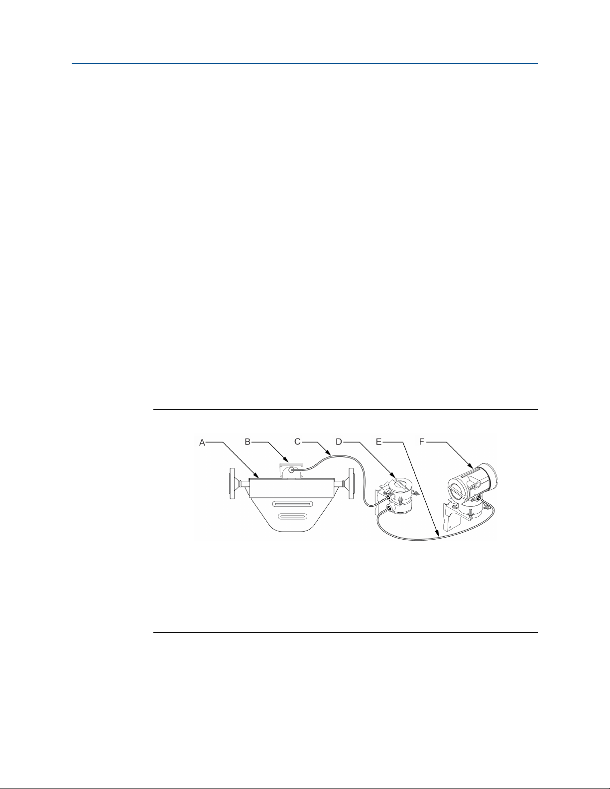
Figure 1-1: MVD remote core processor with remote transmitter
A. Sensor
B. Junction box
C. 9-wire cable
D. Core processor
E. 4-wire cable
F. Transmitter
Installation Instructions 7
Page 8

Planning the installation Installation Manual
October 2018 MMI-20001965
1.3 Hazardous area installations
If your cable will be installed in a hazardous area, ensure that it meets the hazardous area
requirements.
DANGER
Failure to maintain intrinsic safety in a hazardous area could result in an explosion.
To keep sensor wiring intrinsically safe:
• Keep intrinsically safe (IS) sensor wiring separate from power supply wiring and output
wiring.
• Do not install power cable in the same conduit or cable tray as flowmeter cable.
• Use this document with the appropriate approvals documentation. These manuals are
shipped with the flowmeter or available on the Emerson web site: www.emerson.com.
• For hazardous area installations in Europe, refer to standard EN 60079-14 if national
standards do not apply.
8 Micro Motion CSA-D-MVD Transmitter
Page 9

Installation Manual Transmitter output installation
MMI-20001965 October 2018
2 Transmitter output installation
CSA diagrams for installing various meters.
Table 2-1: List of Drawings for Transmitter output installation
Drawing name Location
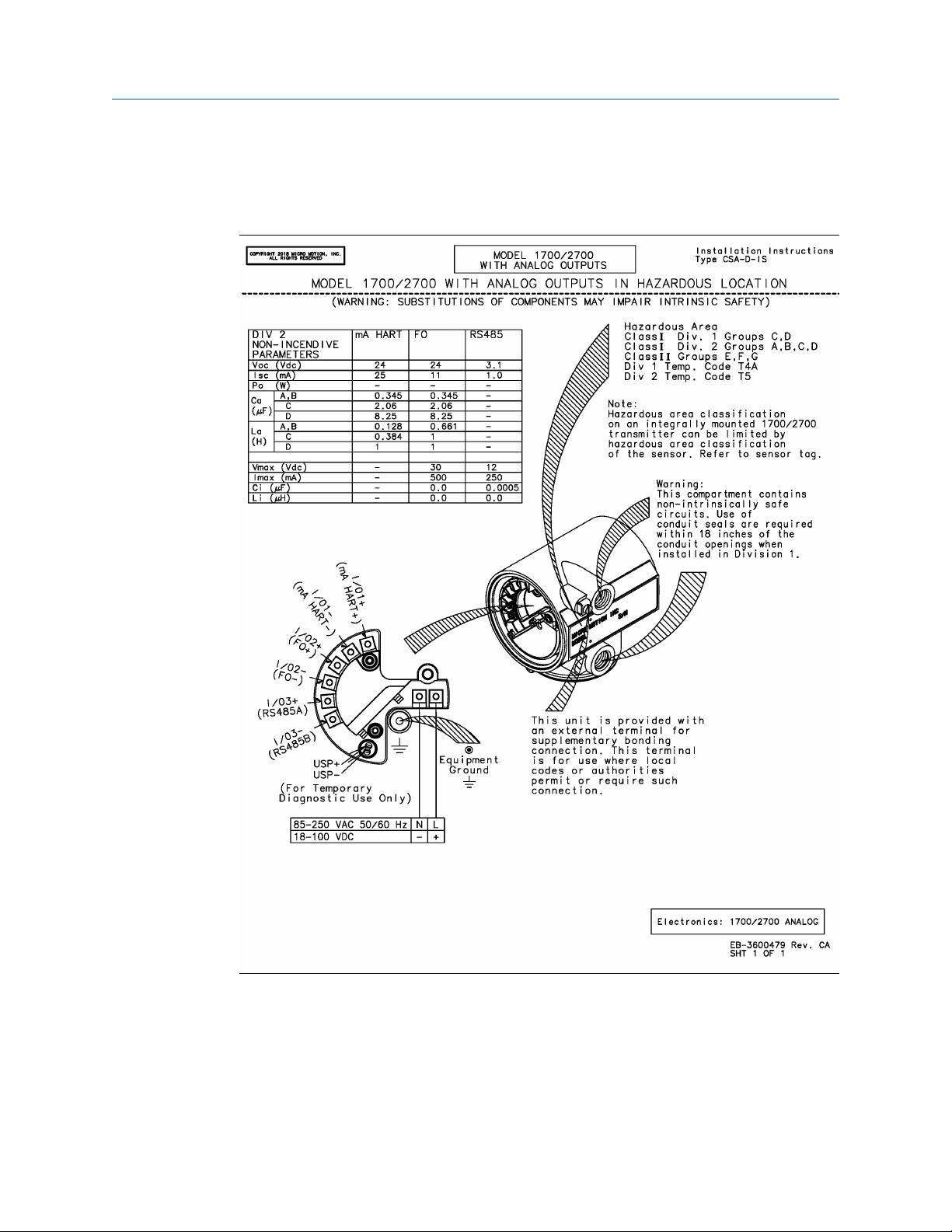
EB-3600479, Revision CA Transmitter output installation: Analog outputs for Model
1700/2700 transmitters
EB-20011794, Revision A Transmitter output installation Model 2750 transmitter with
configurable inputs and outputs
EB-3600667, Revision BA Transmitter output installation: Model 2700 with configurable
inputs and outputs
EB-3600473, Revision DA Transmitter output installation: Profibus-PA outputs for Model
1700/2700 Transmitters
EB-3600629, Revision DA Transmitter output installation Model 1700/2700 with Intrinsically
Safe installation
EB-3600476, Revision DA Transmitter output installation Model 1700/2700 with Fieldbus
Installation Instructions 9
Page 10
Transmitter output installation Installation Manual
October 2018 MMI-20001965
2.1 Transmitter output installation: Analog outputs for Model 1700/2700 transmitters
10 Micro Motion CSA-D-MVD Transmitter
Page 11

Installation Manual Transmitter output installation
MMI-20001965 October 2018
2.2 Transmitter output installation Model 2750 transmitter with configurable inputs and outputs
Installation Instructions 11
Page 12

Transmitter output installation Installation Manual
October 2018 MMI-20001965
2.3 Transmitter output installation: Model 2700 with configurable inputs and outputs
12 Micro Motion CSA-D-MVD Transmitter
Page 13

Installation Manual Transmitter output installation
MMI-20001965 October 2018
2.4 Transmitter output installation: Profibus-PA outputs for Model 1700/2700 Transmitters
Installation Instructions 13
Page 14

Transmitter output installation Installation Manual
October 2018 MMI-20001965
2.5 Transmitter output installation Model 1700/2700 with Intrinsically Safe installation
14 Micro Motion CSA-D-MVD Transmitter
Page 15

Installation Manual Transmitter output installation
MMI-20001965 October 2018
2.6 Transmitter output installation Model 1700/2700 with Fieldbus
Installation Instructions 15
Page 16

Transmitter output installation Installation Manual
October 2018 MMI-20001965
16 Micro Motion CSA-D-MVD Transmitter
Page 17

Installation Manual Model 1700/2700 4-Wire installation
MMI-20001965 October 2018
3 Model 1700/2700 4-Wire installation
Table 3-1: List of Drawings for Model 1700/2700 Transmitter 4-wire installation
Drawing name Location
EB-20003010, Revision A Model 1700/2700 4-wire installation: remote transmitter to
enhanced core processor mounted on sensor
EB-3600482, Revision B Model 1700/2700 Transmitter 4-wire installation – remote
transmitter to core processor mounted on sensor
EB-3005819, Revision C Model 1700-2700 Transmitter 4-wire remote transmitter installation
to core processor mounted on CMF400 sensor with booster
amplifier
EB-1005983, Revision B Model 1700/2700 transmitter 4-wire Remote transmitter to core
processor mounted on D600 sensor
Installation Instructions 17
Page 18

Model 1700/2700 4-Wire installation Installation Manual
October 2018 MMI-20001965
3.1 Model 1700/2700 4-wire installation: remote transmitter to enhanced core processor mounted on sensor
18 Micro Motion CSA-D-MVD Transmitter
Page 19

Installation Manual Model 1700/2700 4-Wire installation
MMI-20001965 October 2018
3.2 Model 1700/2700 Transmitter 4-wire installation – remote transmitter to core processor mounted on sensor
Important
This installation does not apply if you have either a D600 or a CMF400 sensor with a
booster amplifier.
Installation Instructions 19
Page 20

Model 1700/2700 4-Wire installation Installation Manual
October 2018 MMI-20001965
3.3 Model 1700-2700 Transmitter 4-wire remote transmitter installation to core processor mounted on CMF400 sensor with booster amplifier
20 Micro Motion CSA-D-MVD Transmitter
Page 21

Installation Manual Model 1700/2700 4-Wire installation
MMI-20001965 October 2018
3.4 Model 1700/2700 transmitter 4-wire Remote transmitter to core processor mounted on D600 sensor
Installation Instructions 21
Page 22

Model 1700/2700 4-Wire installation Installation Manual
October 2018 MMI-20001965
22 Micro Motion CSA-D-MVD Transmitter
Page 23

Installation Manual Direct host 4-wire installation
MMI-20001965 October 2018
4 Direct host 4-wire installation
Table 4-1: List of Drawings for direct host 4-wire installation
Drawing name Location
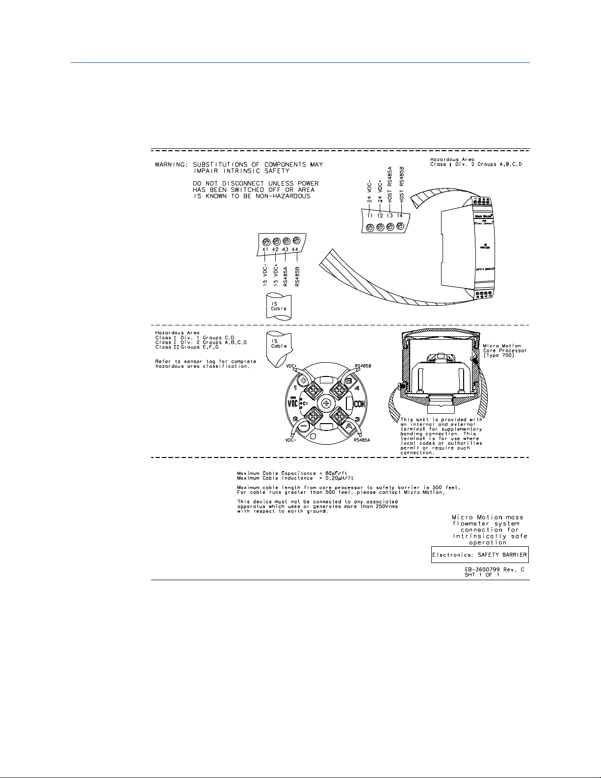
EB-3600799, Revision CA Direct host 4-wire installation – core processor to direct host
through a safety barrier
EB-20003013, Revision A Direct host 4-wire installation of enhanced core processor to a direct
host through a safety barrier
Installation Instructions 23
Page 24
Direct host 4-wire installation Installation Manual
October 2018 MMI-20001965
4.1 Direct host 4-wire installation – core processor to direct host through a safety barrier
24 Micro Motion CSA-D-MVD Transmitter
Page 25

Installation Manual Direct host 4-wire installation
MMI-20001965 October 2018
4.2 Direct host 4-wire installation of enhanced core processor to a direct host through a safety barrier
Installation Instructions 25
Page 26

Direct host 4-wire installation Installation Manual
October 2018 MMI-20001965
26 Micro Motion CSA-D-MVD Transmitter
Page 27
Installation Manual Model 800 enhanced core processor
MMI-20001965 October 2018
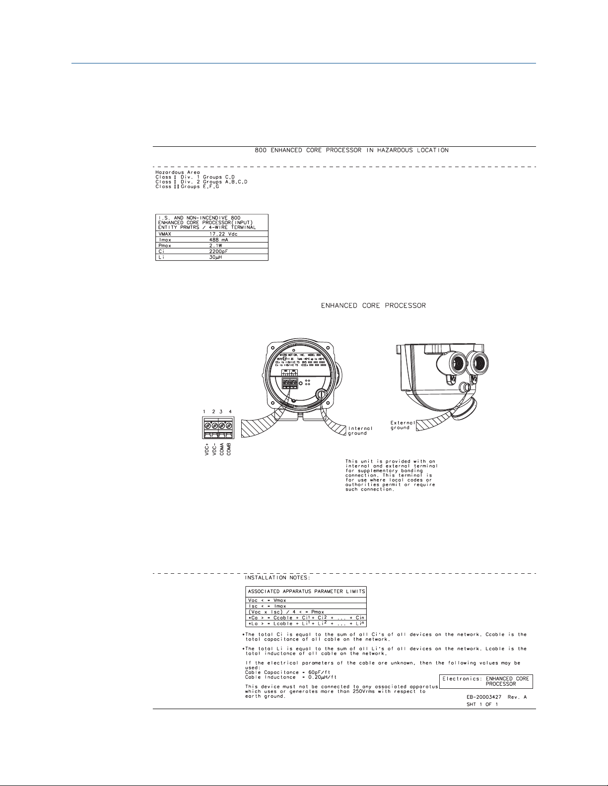
5 Model 800 enhanced core processor
Installation Instructions 27
Page 28

Model 800 enhanced core processor Installation Manual
October 2018 MMI-20001965
28 Micro Motion CSA-D-MVD Transmitter
Page 29

Installation Manual Model 2750 4-wire installation
MMI-20001965 October 2018
6 Model 2750 4-wire installation
Remote transmitter to enhanced core processor mounted on sensor.
Installation Instructions 29
Page 30

Model 2750 4-wire installation Installation Manual
October 2018 MMI-20001965
30 Micro Motion CSA-D-MVD Transmitter
Page 31

Installation Manual Model 1500/2500 4-wire installation
MMI-20001965 October 2018
7 Model 1500/2500 4-wire installation
Table 7-1: List of Drawings for Transmitter Models 1500/2500 4-wire installations
Drawing name Location
EB-20003009, Revision A Remote transmitter to enhanced core processor mounted on sensor
EB-20001220, Revision A Remote transmitter to core processor mounted on CMF, F, H, R,
CNG, and T sensor
EB-20001219, Revision A Remote transmitter to core processor mounted on CMF400 sensor
with booster amplifier
EB-20001218, Revision A Remote transmitter to core processor mounted on D600 sensor
Installation Instructions 31
Page 32

Model 1500/2500 4-wire installation Installation Manual
October 2018 MMI-20001965
7.1 Remote transmitter to enhanced core processor mounted on sensor
32 Micro Motion CSA-D-MVD Transmitter
Page 33

Installation Manual Model 1500/2500 4-wire installation
MMI-20001965 October 2018
7.2 Remote transmitter to core processor mounted on CMF, F, H, R, CNG, and T sensor
Installation Instructions 33
Page 34

Model 1500/2500 4-wire installation Installation Manual
October 2018 MMI-20001965
7.3 Remote transmitter to core processor mounted on CMF400 sensor with booster amplifier
34 Micro Motion CSA-D-MVD Transmitter
Page 35

Installation Manual Model 1500/2500 4-wire installation
MMI-20001965 October 2018
7.4 Remote transmitter to core processor mounted on D600 sensor
Installation Instructions 35
Page 36

Model 1500/2500 4-wire installation Installation Manual
October 2018 MMI-20001965
36 Micro Motion CSA-D-MVD Transmitter
Page 37

Installation Manual Model 3700 transmitter 4-wire installation
MMI-20001965 October 2018
8 Model 3700 transmitter 4-wire
installation
Table 8-1: List of Drawings for Transmitter Models 3700 4-wire installations
Drawing name Location
EB-20003012, Revision A Model 3700 transmitter to enhanced core processor mouted on
sensor
EB-20000224, Revision B Model 3700 transmitter to core processor mounted on CMF, F, H, R,
CNF, and T sensors
EB-20000218, Revision B Remote Model 3700 transmitter to core processor mounted on
CMF400 sensor with booster amplifier
EB-20000221, Revision B Model 3700 remote transmitter to core processor mounted on D600
sensor
Installation Instructions 37
Page 38

Model 3700 transmitter 4-wire installation Installation Manual
October 2018 MMI-20001965
8.1 Model 3700 transmitter to enhanced core processor mouted on sensor
38 Micro Motion CSA-D-MVD Transmitter
Page 39

Installation Manual Model 3700 transmitter 4-wire installation
MMI-20001965 October 2018
8.2 Model 3700 transmitter to core processor mounted on CMF, F, H, R, CNF, and T sensors
Installation Instructions 39
Page 40

Model 3700 transmitter 4-wire installation Installation Manual
October 2018 MMI-20001965
8.3 Remote Model 3700 transmitter to core processor mounted on CMF400 sensor with booster amplifier
40 Micro Motion CSA-D-MVD Transmitter
Page 41

Installation Manual Model 3700 transmitter 4-wire installation
MMI-20001965 October 2018
8.4 Model 3700 remote transmitter to core processor mounted on D600 sensor
Installation Instructions 41
Page 42

Model 3700 transmitter 4-wire installation Installation Manual
October 2018 MMI-20001965
42 Micro Motion CSA-D-MVD Transmitter
Page 43

Installation Manual Model 3500 transmitter 4-wire installation
MMI-20001965 October 2018
9 Model 3500 transmitter 4-wire
installation
Table 9-1: List of Drawings for Transmitter Models 3500 4-wire installations
Drawing name Location
EB-20003011, Revision A Remote model 3500 transmitter to enhanced core processor
mounted on sensor
EB-20000250, Revision B Remote Model 3500 transmitter to core processor mounted on
CMF, F, H, R, CNG and T sensors
EB-20000244, Revision B Remote Model 3500 transmitter to core processor mounted on
CMF400 sensor with booster amplifier
EB-20000247, Revision B Remote Model 3500 transmitter to core processor mounted on
D600 sensor
Installation Instructions 43
Page 44

Model 3500 transmitter 4-wire installation Installation Manual
October 2018 MMI-20001965
9.1 Remote model 3500 transmitter to enhanced core processor mounted on sensor
44 Micro Motion CSA-D-MVD Transmitter
Page 45

Installation Manual Model 3500 transmitter 4-wire installation
MMI-20001965 October 2018
9.2 Remote Model 3500 transmitter to core processor mounted on CMF, F, H, R, CNG and T sensors
Installation Instructions 45
Page 46

Model 3500 transmitter 4-wire installation Installation Manual
October 2018 MMI-20001965
9.3 Remote Model 3500 transmitter to core processor mounted on CMF400 sensor with booster amplifier
46 Micro Motion CSA-D-MVD Transmitter
Page 47

Installation Manual Model 3500 transmitter 4-wire installation
MMI-20001965 October 2018
9.4 Remote Model 3500 transmitter to core processor mounted on D600 sensor
Installation Instructions 47
Page 48

Model 3500 transmitter 4-wire installation Installation Manual
October 2018 MMI-20001965
48 Micro Motion CSA-D-MVD Transmitter
Page 49

Installation Manual Model LFT 4-wire installation to LF sensor
MMI-20001965 October 2018
10 Model LFT 4-wire installation to LF
sensor
Table 10-1: List of Drawings for Transmitter Model LFT 4-wire installations
Drawing name Location
EB-20002225, Revision A Profibus-PA transmitter remotely mounted to LF sensor
EB-20002227, Revision A mA/FO transmitter remotely mounted to LF sensor
EB-20002226, Revision A FOUNDATION Fieldbus™ transmitter remotely mounted to LF sensor
EB-20002229, Revision A Config I/O transmitter remotely mounted to LF sensor
EB-20002223, Revision A DIN rail transmitter remotely mounted to LF sensor
Installation Instructions 49
Page 50

Model LFT 4-wire installation to LF sensor Installation Manual
October 2018 MMI-20001965
10.1 Profibus-PA transmitter remotely mounted to LF sensor
50 Micro Motion CSA-D-MVD Transmitter
Page 51

Installation Manual Model LFT 4-wire installation to LF sensor
MMI-20001965 October 2018
10.2 mA/FO transmitter remotely mounted to LF sensor
Installation Instructions 51
Page 52

Model LFT 4-wire installation to LF sensor Installation Manual
October 2018 MMI-20001965
10.3 FOUNDATION Fieldbus™ transmitter remotely mounted to LF sensor
52 Micro Motion CSA-D-MVD Transmitter
Page 53

Installation Manual Model LFT 4-wire installation to LF sensor
MMI-20001965 October 2018
10.4 Config I/O transmitter remotely mounted to LF sensor
Installation Instructions 53
Page 54

Model LFT 4-wire installation to LF sensor Installation Manual
October 2018 MMI-20001965
10.5 DIN rail transmitter remotely mounted to LF sensor
54 Micro Motion CSA-D-MVD Transmitter
Page 55

Installation Manual Model 1700/2700 transmitter 9-wire integral installations
MMI-20001965 October 2018
11 Model 1700/2700 transmitter 9-wire
integral installations
Table 11-1: List of Drawings for Transmitter Models 1700/2700 9-wire integral
installations
Drawing name Location
EB-20001058 Revision C Model 1700/2700 transmitter with integrally-mounted processor to
junction box on CMF, F, H, T, D, and DL sensors
EB-30006199, Revision A Model 1700/2700 transmitter with integrally-mounted core
processor to 9-wire junction box on CMF400 sensor with booster
amplifier
EB-10005117, Revision A Model 1700/2700 transmitter with integrally-mounted core
processor to junction box on D600 sensor
EB-36000538, Revision A Model 1700/2700 transmitter with integrally-mounted core
processor to 9-wire junction box on DT sensor
Installation Instructions 55
Page 56

Model 1700/2700 transmitter 9-wire integral installations Installation Manual
October 2018 MMI-20001965
11.1 Model 1700/2700 transmitter with integrallymounted processor to junction box on CMF, F,
H, T, D, and DL sensors
Note
This installation process does not apply to CMF400 sensors with a booster amplifier or to
D600 sensors.
56 Micro Motion CSA-D-MVD Transmitter
Page 57

Installation Manual Model 1700/2700 transmitter 9-wire integral installations
MMI-20001965 October 2018
11.2 Model 1700/2700 transmitter with integrallymounted core processor to 9-wire junction box
on CMF400 sensor with booster amplifier
Installation Instructions 57
Page 58

Model 1700/2700 transmitter 9-wire integral installations Installation Manual
October 2018 MMI-20001965
11.3 Model 1700/2700 transmitter with integrallymounted core processor to junction box on
D600 sensor
58 Micro Motion CSA-D-MVD Transmitter
Page 59

Installation Manual Model 1700/2700 transmitter 9-wire integral installations
MMI-20001965 October 2018
11.4 Model 1700/2700 transmitter with integrallymounted core processor to 9-wire junction box
on DT sensor
Installation Instructions 59
Page 60

Model 1700/2700 transmitter 9-wire integral installations Installation Manual
October 2018 MMI-20001965
60 Micro Motion CSA-D-MVD Transmitter
Page 61

Installation Manual Model 1700/2700 9-wire remote installations
MMI-20001965 October 2018
12 Model 1700/2700 9-wire remote
installations
Table 12-1: List of Drawings for Transmitter Models 1700/2700 9-wire remote
installations
Drawing name Location
EB-20001060 Revision BA Model 1700/2700 transmitter installation to remote core processor
to 9-wire junction box on CMF, F, T, D, and DL sensors
EB-3007061, Revision B Model 1700/2700 transmitter to remote mount core processor to 9-
wire junction box on CMF400 sensor with booster amplifier
EB-10005119, Revision B Model 1700/2700 transmitter to remote core processor to 9-wire
junction box on D600 sensor
EB-3600674, Revision C Model 1700/2700 transmitter to remote core processor to 9-wire
junction box on DT sensor
Installation Instructions 61
Page 62

Model 1700/2700 9-wire remote installations Installation Manual
October 2018 MMI-20001965
12.1 Model 1700/2700 transmitter installation to remote core processor to 9-wire junction box on CMF, F, T, D, and DL sensors
Note
This installation process does not apply to CMF400 sensors with a booster amplifier or to
D600 sensors.
62 Micro Motion CSA-D-MVD Transmitter
Page 63

Installation Manual Model 1700/2700 9-wire remote installations
MMI-20001965 October 2018
12.2 Model 1700/2700 transmitter to remote mount core processor to 9-wire junction box on CMF400 sensor with booster amplifier
Installation Instructions 63
Page 64

Model 1700/2700 9-wire remote installations Installation Manual
October 2018 MMI-20001965
12.3 Model 1700/2700 transmitter to remote core processor to 9-wire junction box on D600 sensor
64 Micro Motion CSA-D-MVD Transmitter
Page 65

Installation Manual Model 1700/2700 9-wire remote installations
MMI-20001965 October 2018
12.4 Model 1700/2700 transmitter to remote core processor to 9-wire junction box on DT sensor
Installation Instructions 65
Page 66

Model 1700/2700 9-wire remote installations Installation Manual
October 2018 MMI-20001965
66 Micro Motion CSA-D-MVD Transmitter
Page 67

Installation Manual Model 1500/2500 9-wire installation
MMI-20001965 October 2018
13 Model 1500/2500 9-wire installation
Table 13-1: List of Drawings for Transmitter Models 1500/2500 9-wire installations
Drawing name Location
EB-20001221 Revision BA Model 1500/2500 transmitter to remote mount core processor to 9-
wire junction box on CMF, D (except D600), DL, F, H, and T sensors
EB-20001223, Revision A Model 1500/2500 transmitter to remote core processor to 9-wire
junction box on CMF400 sensor with booster amplifier
EB-20001222, Revision A Model 1500/2500 transmitter to core processor to 9-wire junction
box on D600 sensor
EB-20001225, Revision A Model 1500/2500 transmitter to core processor to 9-wire junction
box on DT sensor
Installation Instructions 67
Page 68

Model 1500/2500 9-wire installation Installation Manual
October 2018 MMI-20001965
13.1 Model 1500/2500 transmitter to remote mount core processor to 9-wire junction box on CMF, D (except D600), DL, F, H, and T sensors
68 Micro Motion CSA-D-MVD Transmitter
Page 69

Installation Manual Model 1500/2500 9-wire installation
MMI-20001965 October 2018
13.2 Model 1500/2500 transmitter to remote core processor to 9-wire junction box on CMF400 sensor with booster amplifier
Installation Instructions 69
Page 70

Model 1500/2500 9-wire installation Installation Manual
October 2018 MMI-20001965
13.3 Model 1500/2500 transmitter to core processor to 9-wire junction box on D600 sensor
70 Micro Motion CSA-D-MVD Transmitter
Page 71

Installation Manual Model 1500/2500 9-wire installation
MMI-20001965 October 2018
13.4 Model 1500/2500 transmitter to core processor to 9-wire junction box on DT sensor
Installation Instructions 71
Page 72

Model 1500/2500 9-wire installation Installation Manual
October 2018 MMI-20001965
72 Micro Motion CSA-D-MVD Transmitter
Page 73

Installation Manual Model 3700 9-wire installation instructions
MMI-20001965 October 2018
14 Model 3700 9-wire installation
instructions
Table 14-1: List of Drawings for Transmitter Models 3700 9-wire installations
Drawing name Location
EB-20001053, Revision CA Model 3700 transmitter to remote mount core processor to 9-wire
junction box on CMF, D (except D600), DL, F, H, and T sensors
EB-20000212, Revision C Model 3700 transmitter to remote core processor to 9-wire junction
box for CMF300A sensor
EB-20000203, Revision B Model 3700 transmitter to remote core processor to 9-wire junction
box on CMF400 sensor with booster amplifier
EB-20000206, Revision B Model 3700 transmitter to remote core processor to 9-wire junction
box on D600
EB-20000215, Revision B Model 3700 transmitter to remote mount core processor to 9-wire
junction box on DT sensor
Installation Instructions 73
Page 74

Model 3700 9-wire installation instructions Installation Manual
October 2018 MMI-20001965
14.1 Model 3700 transmitter to remote mount core processor to 9-wire junction box on CMF, D (except D600), DL, F, H, and T sensors
74 Micro Motion CSA-D-MVD Transmitter
Page 75

Installation Manual Model 3700 9-wire installation instructions
MMI-20001965 October 2018
14.2 Model 3700 transmitter to remote core processor to 9-wire junction box on CMF400 sensor with booster amplifier
Installation Instructions 75
Page 76

Model 3700 9-wire installation instructions Installation Manual
October 2018 MMI-20001965
14.3 Model 3700 transmitter to remote core processor to 9-wire junction box on D600
76 Micro Motion CSA-D-MVD Transmitter
Page 77

Installation Manual Model 3700 9-wire installation instructions
MMI-20001965 October 2018
14.4 Model 3700 transmitter to remote mount core processor to 9-wire junction box on DT sensor
Installation Instructions 77
Page 78

Model 3700 9-wire installation instructions Installation Manual
October 2018 MMI-20001965
78 Micro Motion CSA-D-MVD Transmitter
Page 79

Installation Manual Model 3500 9-wire installation
MMI-20001965 October 2018
15 Model 3500 9-wire installation
Table 15-1: List of Drawings for Transmitter Models 3500 9-wire installations
Drawing name Location
EB-20001051, Revision CA Model 3500 transmitter to remote core processor to 9-wire junction
box on CMF, D (except D600), DL, H, and T sensors
EB-20000229, Revision BA Model 3500 transmitter to remote core processor to 9-wire junction
box on CMF400 sensor with boost amplifier
EB-20000232, Revision B Model 3500 transmitter to remote mount core processor to 9-wire
junction box on D600 sensor
EB-20000241, Revision B Model 3500 transmitter to remote mount core processor to 9-wire
junction box on DT sensor
Installation Instructions 79
Page 80

Model 3500 9-wire installation Installation Manual
October 2018 MMI-20001965
15.1 Model 3500 transmitter to remote core processor to 9-wire junction box on CMF, D (except D600), DL, H, and T sensors
80 Micro Motion CSA-D-MVD Transmitter
Page 81

Installation Manual Model 3500 9-wire installation
MMI-20001965 October 2018
15.2 Model 3500 transmitter to remote core processor to 9-wire junction box on CMF400 sensor with boost amplifier
Installation Instructions 81
Page 82

Model 3500 9-wire installation Installation Manual
October 2018 MMI-20001965
15.3 Model 3500 transmitter to remote mount core processor to 9-wire junction box on D600 sensor
82 Micro Motion CSA-D-MVD Transmitter
Page 83

Installation Manual Model 3500 9-wire installation
MMI-20001965 October 2018
15.4 Model 3500 transmitter to remote mount core processor to 9-wire junction box on DT sensor
Installation Instructions 83
Page 84

Model 3500 9-wire installation Installation Manual
October 2018 MMI-20001965
84 Micro Motion CSA-D-MVD Transmitter
Page 85

Installation Manual D600 remote booster amplifier installation
MMI-20001965 October 2018
16 D600 remote booster amplifier
installation
Table 16-1: List of Drawings for D600 remote booster amplifier installation
Drawing name Location
EB-1005084, Revision B D600 remote booster amplifier installation with core processor
remotely mounted from sensor and transmitter
EB-1005085, Revision B D600 remote booster amplifier with junction box remotely mounted
from sensor and transmitter
Installation Instructions 85
Page 86

D600 remote booster amplifier installation Installation Manual
October 2018 MMI-20001965
16.1 D600 remote booster amplifier installation with core processor remotely mounted from sensor and transmitter
86 Micro Motion CSA-D-MVD Transmitter
Page 87

Installation Manual D600 remote booster amplifier installation
MMI-20001965 October 2018
16.2 D600 remote booster amplifier with junction box remotely mounted from sensor and transmitter
Installation Instructions 87
Page 88

D600 remote booster amplifier installation Installation Manual
October 2018 MMI-20001965
88 Micro Motion CSA-D-MVD Transmitter
Page 89

Installation Manual List of drawings
MMI-20001965 October 2018
A List of drawings
Table A-1: List of Drawings
Drawing name Location
EB-1005084 Revision B D600 remote booster amplifier installation with core processor
remotely mounted from sensor and transmitter
EB-1005085 Revision B D600 remote booster amplifier with junction box remotely mounted
from sensor and transmitter
EB-10005117 Revision B Model 1700/2700 transmitter with integrally-mounted core
processor to junction box on D600 sensor
EB-1005119 Revision B Model 1700/2700 transmitter to remote core processor to 9-wire
junction box on D600 sensor
EB-2000203 Revision B Model 3700 transmitter to remote core processor to 9-wire junction
box on CMF400 sensor with booster amplifier
EB-20000206 Revision B Model 3700 transmitter to remote core processor to 9-wire junction
box on D600
EB-20000215 Revision B Model 3700 transmitter to remote mount core processor to 9-wire
junction box on DT sensor
EB-2000218 Revision B Remote Model 3700 transmitter to core processor mounted on
CMF400 sensor with booster amplifier
EB-2000221 Revision B Model 3700 remote transmitter to core processor mounted on D600
sensor
EB-20000224, Revision B Model 3700 transmitter to core processor mounted on CMF, F, H, R,
CNF, and T sensors
EB-20000229, Revision BA Model 3500 transmitter to remote core processor to 9-wire junction
box on CMF400 sensor with boost amplifier
EB-20000232, Revision B Model 3500 transmitter to remote mount core processor to 9-wire
junction box on D600 sensor
EB-20000241, Revision B Model 3500 transmitter to remote mount core processor to 9-wire
junction box on DT sensor
EB-20000244, Revision B Remote Model 3500 transmitter to core processor mounted on
CMF400 sensor with booster amplifier
EB-20000247, Revision B Remote Model 3500 transmitter to core processor mounted on
D600 sensor
EB-20000250, Revision B Remote Model 3500 transmitter to core processor mounted on
CMF, F, H, R, CNG and T sensors
EB-20001051, Revision C Model 3500 transmitter to remote core processor to 9-wire junction
box on CMF, D (except D600), DL, H, and T sensors
EB-20001053, Revision C Model 3700 transmitter to remote mount core processor to 9-wire
junction box on CMF, D (except D600), DL, F, H, and T sensors
EB-20001058, Revision, C Model 1700/2700 transmitter with integrally-mounted processor to
junction box on CMF, F, H, T, D, and DL sensors
Installation Instructions 89
Page 90

List of drawings Installation Manual
October 2018 MMI-20001965
Table A-1: List of Drawings (continued)
Drawing name Location
EB-20001060, Revision, BA Model 1700/2700 transmitter installation to remote core processor
to 9-wire junction box on CMF, F, T, D, and DL sensors
EB-20001218, Revision A Remote transmitter to core processor mounted on D600 sensor
EB-20001219, Revision A Remote transmitter to core processor mounted on CMF400 sensor
with booster amplifier
EB-20001220, Revision A Remote transmitter to core processor mounted on CMF, F, H, R,
CNG, and T sensor
EB-20001221 Revision B Model 1500/2500 transmitter to remote mount core processor to 9-
wire junction box on CMF, D (except D600), DL, F, H, and T sensors
EB-20001222, Revision A Model 1500/2500 transmitter to core processor to 9-wire junction
box on D600 sensor
EB-20001223, Revision A Model 1500/2500 transmitter to remote core processor to 9-wire
junction box on CMF400 sensor with booster amplifier
EB-20001225, Revision A Model 1500/2500 transmitter to core processor to 9-wire junction
box on DT sensor
EB-20002223, Revision A DIN rail transmitter remotely mounted to LF sensor
EB-20002225, Revision A Profibus-PA transmitter remotely mounted to LF sensor
EB-20002226, Revision A FOUNDATION Fieldbus™ transmitter remotely mounted to LF sensor
EB-20002227, Revision A mA/FO transmitter remotely mounted to LF sensor
EB-20002229, Revision A Config I/O transmitter remotely mounted to LF sensor
EB-20003009, Revision A Remote transmitter to enhanced core processor mounted on sensor
EB-20003010, Revision A Model 1700/2700 4-wire installation: remote transmitter to
enhanced core processor mounted on sensor
EB-20003011, Revision A Remote model 3500 transmitter to enhanced core processor
mounted on sensor
EB-20003012, Revision A Model 3700 transmitter to enhanced core processor mouted on
sensor
EB-20003013, Revision A Direct host 4-wire installation of enhanced core processor to a direct
host through a safety barrier
EB-20003427, Revision A Model 800 enhanced core processor
EB-20011794, Revision A Transmitter output installation Model 2750 transmitter with
configurable inputs and outputs
EB-20011795, Revision A Model 2750 4-wire installation
EB-3005819, Revision C Model 1700-2700 Transmitter 4-wire remote transmitter installation
to core processor mounted on CMF400 sensor with booster
amplifier
90 Micro Motion CSA-D-MVD Transmitter
Page 91

Installation Manual List of drawings
MMI-20001965 October 2018
Table A-1: List of Drawings (continued)
Drawing name Location
EB-3006199, Revision C Model 1700/2700 transmitter with integrally-mounted core
processor to 9-wire junction box on CMF400 sensor with booster
amplifier
EB-3007061, Revision B Model 1700/2700 transmitter to remote mount core processor to 9-
wire junction box on CMF400 sensor with booster amplifier
EB-3600473, Revision DA Transmitter output installation: Profibus-PA outputs for Model
1700/2700 Transmitters
EB-3600476, Revision DA Transmitter output installation Model 1700/2700 with Fieldbus
EB-3600479, Revision CA Transmitter output installation: Analog outputs for Model
1700/2700 transmitters
EB-3600482, Revision BA Model 1700/2700 Transmitter 4-wire installation – remote
transmitter to core processor mounted on sensor
EB-3600538, Revision B Model 1700/2700 transmitter with integrally-mounted core
processor to 9-wire junction box on DT sensor
EB-3600629, Revision D Transmitter output installation Model 1700/2700 with Intrinsically
Safe installation
EB-3600667, Revision B Transmitter output installation: Model 2700 with configurable
inputs and outputs
EB-3600674, Revision C Model 1700/2700 transmitter to remote core processor to 9-wire
junction box on DT sensor
EB-3600799, Revision CA Direct host 4-wire installation – core processor to direct host
through a safety barrier
Installation Instructions 91
Page 92

*MMI-20001965*
MMI-20001965
Rev. EB
2018
Micro Motion Inc. USA
Worldwide Headquarters
7070 Winchester Circle
Boulder, Colorado USA 80301
T +1 303-527-5200
T +1 800-522-6277
F +1 303-530-8459
www.emerson.com
Micro Motion Asia
Emerson Automation Solutions
1 Pandan Crescent
Singapore 128461
Republic of Singapore
T +65 6363-7766
F +65 6770-8003
©
2018 Micro Motion, Inc. All rights reserved.
The Emerson logo is a trademark and service mark of Emerson Electric Co. Micro Motion, ELITE,
ProLink, MVD and MVD Direct Connect marks are marks of one of the Emerson Automation
Solutions family of companies. All other marks are property of their respective owners.
Micro Motion Europe
Emerson Automation Solutions
Neonstraat 1
6718 WX Ede
The Netherlands
T +31 (0) 70 413 6666
F +31 (0) 318 495 556
www.micromotion.nl
Micro Motion United Kingdom
Emerson Automation Solutions
Emerson Process Management Limited
Horsfield Way
Bredbury Industrial Estate
Stockport SK6 2SU U.K.
T +44 0870 240 1978
F +44 0800 966 181
 Loading...