

Page 1
Large operator interface for easy setup & control
• 128 x 128 pixel display enhances view of process
• Easy to read menus and advanced help system
Transmitter and discrete control from a single instrument
• Functions as an advanced process transmitter or as a discrete
batch controller, with 8 I/O channels for maximum adaptability
•HART
®
and Modbus® support expand communications options
Wide variety of applications
• Concentration & net flow measurement
• Custody transfer with batch control
• Patented meter verification application
Product Data Sheet
PS-00291, Rev. B
May 2007
Micro Motion® Series 3000 Transmitters and Discrete Controllers
Micro Motion® Series 3000 electronics combine transmitter functions and
PLC capabilities in one instrument. Series 3000 models feature MVD™
technology, providing high-speed DSP capabilities and a broad range of
specialty applications.
3300
3350
2400S
1700
2700
1500
2500
Frequency-input
discrete controller
Compact integral
transmitter
Versatile
field-mount
transmitter
Compact
control-room
transmitter
3500
3700
Integrated control
and measurement
platform
Page 2
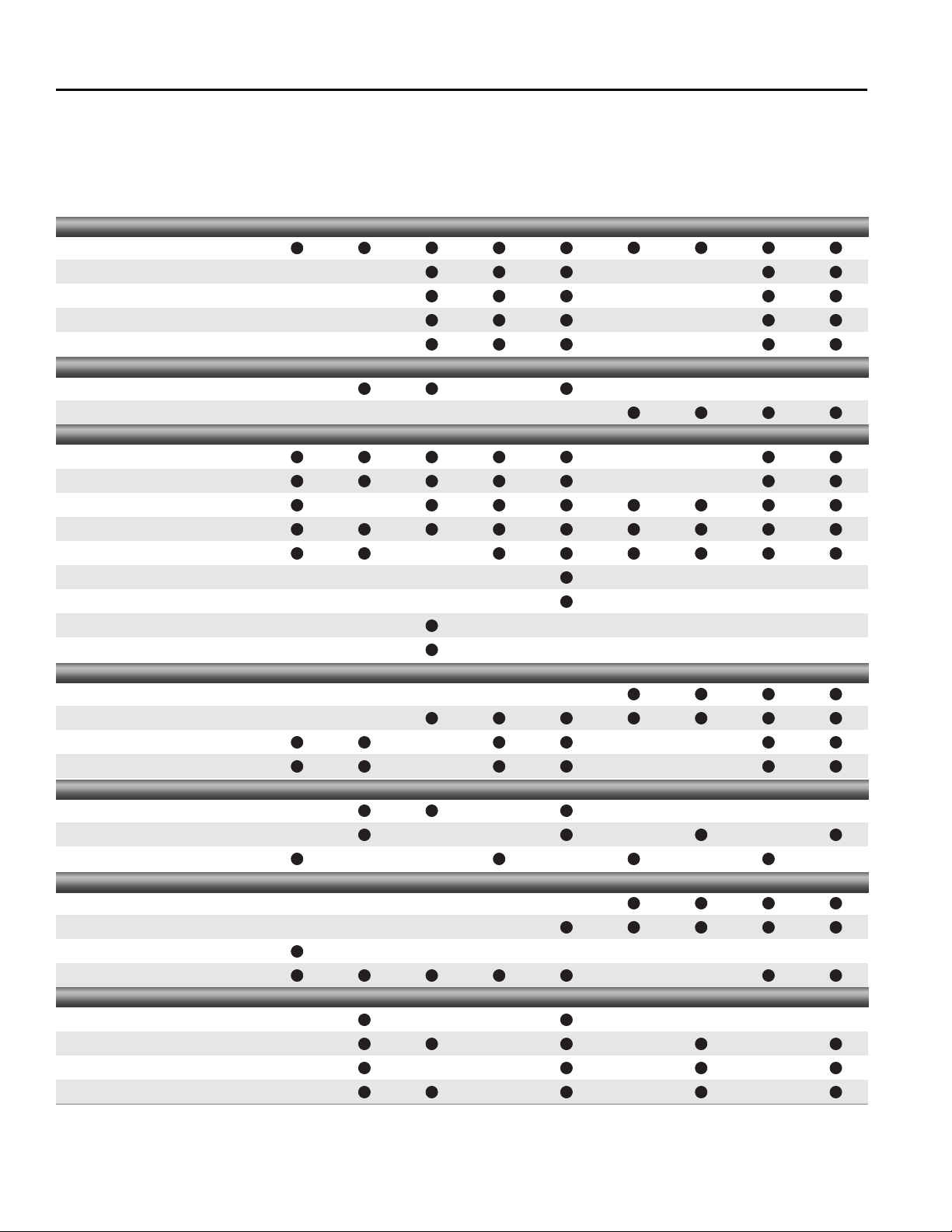
Micro Motion transmitters and controllers
Output variables
Local display
Outputs
Inputs
Mounting
Application type
Hazardous approvals
Micro Motion transmitters and controllers fit a wide variety of application needs. The table below can help
determine which Micro Motion products are right for your process. For more detailed product information,
consult the appropriate Product Data Sheet or contact your local Micro Motion representative.
1500 1700 2400S 2500 2700 3300 3350 3500 3700
Mass / volume flow
Net mass / volume flow
Temperature
Density
Concentration
2-line
Multi-line
4–20 mA
10 kHz pulse
Discrete
HART®
Modbus®
FOUNDATION fieldbus™
PROFIBUS-PA
PROFIBUS-DP
DeviceNet®
10 kHz pulse
Discrete
4-wire Coriolis sensor
9-wire Coriolis sensor
Integral – Field
Remote – Field
Remote – Control room
Batch controller
Custody transfer
Filling & dosing
Meter verification
C1D1
C1D2
Zone 1
Zone 2
2 Micro Motion® Series 3000 Transmitters and Discrete Controllers
Page 3

Series 3000 transmitters and discrete controllers
Contents
Housings . . . . . . . . . . . . . . . . . . . . . . . . . . . . . . . . 4
Applications. . . . . . . . . . . . . . . . . . . . . . . . . . . . . . 4
Interface/display. . . . . . . . . . . . . . . . . . . . . . . . . . . 5
Electrical connections . . . . . . . . . . . . . . . . . . . . . . 5
Input signals . . . . . . . . . . . . . . . . . . . . . . . . . . . . . 6
Output signals . . . . . . . . . . . . . . . . . . . . . . . . . . . . 6
Environmental specifications. . . . . . . . . . . . . . . . . 8
Power supply. . . . . . . . . . . . . . . . . . . . . . . . . . . . . 8
Hazardous area classifications . . . . . . . . . . . . . . . 9
Model 3100 accessory . . . . . . . . . . . . . . . . . . . . 10
Model 3500/3700 liquid flow performance . . . . . 10
Model 3500/3700 density
performance (liquid only). . . . . . . . . . . . . . . . . . . 11
Model 3500/3700 gas flow performance. . . . . . . 11
Weight. . . . . . . . . . . . . . . . . . . . . . . . . . . . . . . . . 11
Dimensions . . . . . . . . . . . . . . . . . . . . . . . . . . . . . 12
Ordering information . . . . . . . . . . . . . . . . . . . . . . 16
MVD technology. MVD technology makes your
Micro Motion meter work smarter. Front-end digital
processing dramatically reduces signal noise and
gives you faster response time compared to analog
devices.
Only MVD technology allows you to:
• Measure multiple variables
• Install easily with a standard 4-wire signal cable
• Identify and resolve problems easily with built-in
smart diagnostics
• Choose transmitter capabilities based on your
application’s needs
• Upgrade transmitter functionality as needed
Series 3000 transmitters and controllers with MVD
technology.
deliver process measurement and discrete control
based on direct input from a Micro Motion Coriolis
meter. Model 3300 and 3350 controllers provide
discrete control based on a frequency input from a
remote transmitter. Series 3000 models are
available with specialty applications, such as batch
control, enhanced density measurement, petroleum
measurement, custody transfer, and meter
verification.
Configuration, operation, and maintenance are all
accomplished using the innovativ e Series 3000 user
interface. The interface features a large, easy-touse backlit display with big, tactile-feedback push
buttons. Other user interfaces (such as hand-held
communication devices) are not required, but can
be used. Modbus and HART communication allow
configuration devices such as ProLink II, AMS, and
HART Communicators to be used with the
Series 3000, and the Series 3000 can be integrated
into a PlantWeb network.
Model 3500 and 3700 transmitters
Micro Motion® Series 3000 Transmitters and Discrete Controllers 3
Page 4

Housings
Rack-mount 19-inch (486.2 mm) rack-mount housing meets DIN standard 41494 and IEC 297-3
Front panel is rated IP40
Panel-mount Front panel with bezel is rated NEMA 4X (IP65)
Field-mount Compartment with threaded cover contains electronics
Terminal compartment contains:
• Non-intrinsically safe compartment with input/output and power supply terminals
• Intrinsically safe compartment with interface/display, sensor terminals (Model 3700 only), and
optional input and output terminals
Mounting bracket and interface/display rotate to allow mounting in four different orientations
Rated NEMA 4X (IP67)
Applications
Process monitor/totalizer Process monitoring and totalizing for multiple variables, including mass flow , v olume flo w, density,
and temperature.
Discrete batch control • Configuration of up to six preset batch recipes
• One-stage or two-stage batch control
• End-of-batch warning and batch-overrun alarms
• Configuration by quantity or by percent of target for primary valve closure, secondary valve
opening and closure, end warning, and batch overrun
• Configuration for target lockout, or for target adjustment during batch operation
• Automatic overshoot compensation
Meter verification Provides in-situ assessment of a Micro Motion Coriolis meter, determining whether the meter has
been affected by erosion, corrosion, or other influences affecting meter calibration. No secondary
references are required to perform this operation.
Enhanced density Enhanced density measurement for a number of applications, including:
• %HFCS, °Brix, °Plato, °Balling,
• °Baumé at SG60/60
• Density at reference temperature
• Specific gravity
• Concentration derived from reference density
• Concentration derived from specific gravity
Custody transfe r • Physical and software security
• Security-alarm posting
• Mass or volume totalizer that can be configured by the user
• Custom formatting of receipt tickets
• Audit trail of configuration changes
• Multidrop printing capability
Petroleum measurement (API) Provides API process variables, such as API volume flow and API average density.
4 Micro Motion® Series 3000 Transmitters and Discrete Controllers
Page 5

Interface/display
Display
Models 3300 and 3500 Backlit LCD, 128 × 128 pixel, bit map
Adjustable contrast
Non-glare, chemical-resistant acrylic lens
Models 3350 and 3700 Backlit LCD, 128 × 128 pixel, bit map
Adjustable contrast
Non-glare tempered glass lens
Suitable for hazardous area installation
Keypad membrane switch Large push buttons with tactile feedback
Software-defined function keys
Chemical-resistant polyester
Electrical connections
Input and output connections
Rack-mount Type D connectors per DIN standard 41612 (IEC 603-2)
Available as solder tails (standard) or screw terminals (optional)
Screw terminals accept 24 AWG (0.25 mm
2
) to 16 AWG (1.5 mm2) wires
Panel-mount Screw terminals (standard) or I/O cable with remote DIN rail-mount screw
terminals (optional)
Remote terminals attach to any of four rail types. I/O cable is available in lengths of 2, 5, and 10
feet (0.6, 1.5, and 3 meters)
2
Screw terminals accept 24 AWG (0.25 mm
) to 16 AWG (1.5 mm2) wires
Field-mount Two color-coded wiring compartments:
• Compartment with intrinsically safe terminals has two 3/4-inch NPT or M20 × 1.5 conduit
openings
• Compartment with non-intrinsically safe terminals has three 3/4-inch NPT or M20 × 1.5
conduit openings
2
Screw terminals accept 22 AWG (0.34 mm
) to 16 AWG (1.5 mm2) wires
Power connection
Rack-mount Screw terminals are fixed to rack chassis
Ground makes first and breaks last
2
Screw terminals accept 18 AWG (0.75 mm
Panel-mount Screw terminals accept 18 AWG (0.75 mm
Field-mount Screw terminals accept 18 AWG (0.75 mm
) to 14 AWG (2.5 mm2) wires
2
) to 14 AWG (2.5 mm2) wires
2
) to 12 AWG (4.0 mm2) wires
Micro Motion® Series 3000 Transmitters and Discrete Controllers 5
Page 6

Input signals
Non-intrinsically safe input signals
One 2-wire
frequency/pulse input
Frequency range 0–20,000 Hz
Minimum pulse width 25 μ-sec
Power Sourcing or sinking
Voltage 0–0.8 VDC low state
Current Nominal 5 mA pull-up
3–30 VDC high state
Two discrete
momentary inputs
Intrinsically safe input signals
One 4-wire Coriolis sensor signal input with ground
Pulse width 0.15 sec minimum
Voltage 0–0.8 VDC low state
Output signals
Non-intrinsically safe output signals
Two active
4–20 mA outputs
Three discrete outputs Configurable for the application
Isolated to ±50 VDC from all other outputs and earth ground
Maximum load limit of 1000 Ohms
Output is linear with process from 3.8 to 20.5 mA per NAMUR NE43 (June 1994)
Polarity Active high or active low, software selectable
Power Internal pull-up to 24 V
Voltage 24 VDC nominal
Current Sourcing at 5.6 mA when V
3–30 VDC high state
Dry contacts
= 3 VDC
out
Sinking up to 500 mA at 30 VDC maximum
One 2-wire
frequency/pulse output
(1) The crossover frequency depe nds on the configured value of the pulse width. At the min imum pulse width value of 0.543 ms, the
crossover frequency is 922 Hz. At th e maximum pulse width value of 277 ms, the crossover frequency is 1.8 Hz.
6 Micro Motion® Series 3000 Transmitters and Discrete Controllers
Scalable to 10,000 Hz
Output is linear with flow rate to 12,500 Hz
Pulse width 50% duty cycle above the crossover frequency
Configurable between 0.543 ms and 277 ms
Polarity Active high or active low, software selectable
Power Active or passive, software selectable
Voltage 24 VDC nominal, active
30 VDC applied maximum, passive
Current Sourcing at 10 mA at 3 VDC, active
Sinking at 500 mA, active or passive
(1)
Page 7

Output signals continued
Fault indication
When a fault is detected, outputs go to configured states. User can select upscale, downscale, internal zero, or none. Milliamp
outputs conform to NAMUR NE43 (June 1994).
Upscale Milliamp 21 to 24 mA, user configurab l e
Frequency 15,000 Hz
Downscale Milliamp 1 to 3.6 mA, user configurable
Frequency 0 Hz
Internal zero Drives the mA and frequency outputs for process variables to zero values
None Ignores fault conditions
Digital communications
RS-485 port One pair of terminals supports SP (service port) mode or RS-485 mode. On device power-up , the
user has 10 seconds to connect in SP mode. After 10 seconds, the terminals switch to RS-485
mode. The communication parameters in SP mode are:
Data rate 38,400 baud
Parity No parity
Stop bit One stop bit
Address 111
In RS-485 mode, the Series 3000 can communicate via Modbus RTU, Modbus ASCII, or HART
protocols. The communication parameters are configurable with ProLink II software, Modbus, or
the display. The shipped default parameters are:
Data rate 9600 baud
Parity Odd
Stop bit One stop bit
(1)
The RS-485 port can also be configured as a printer port (see below).
HART Bell 202
Printer port The RS-485 port can be configured as a printer port. When the RS-485 port is
(1) Using HART, it is possible to configure basic transmitter functionality, and read/write batch setpoints and totals. Series 3000 batch
applications or enhanced density applications canno t be configured using HART. Using Modbus, all transmitter functionality, batch
commands, and batch applications can be controlled.
(1)
The HART Bell 202 signal is superimposed on the primary mA output, and is available for host
system interface. The HART Bell 202 communication parameters are:
Frequency 1.2 and 2.2 KHz
Amplitude 0.8 mA peak-to-peak
Data rate 1200 baud
Resistance Loop requires 250 to 600 Ohms resistance
configured as a printer port, it cannot be used for any other function.
Requires external RS-232 adapter (not included)
Bidirectional with Epson printer; send only with all other printers and when using a multidrop
configuration
Micro Motion® Series 3000 Transmitters and Discrete Controllers 7
Page 8

Environmental specifications
EMI effects All Ser ies 3000 devices Meet EMC directive 89/336/EEC per EN 61326 Industrial, and all Series
3000 devices conform to NAMUR NE21 (June 1997).
Ambient temperature effect On analog outputs ±0.005% of span per °C
(1)
Ambient temperature limits
Temperature accuracy Models 3500 and 3700 ±1.0 °C ±0.5% of reading in °C
Temperature repeatability Models 3500 and 3700 ±0.2 °C
Humidity limits 5 to 95% relative humidity, non-condensing at 140 °F (60 °C)
Vibration limits Per IEC 68-2-6, endurance sweep, 5 to 2000 Hz, 50 sweep cycles at 1.0 g
(1) If exposed to direct sunlight, the ambient temperature can be expected to rise by an additional 50 °F (10 °C).
Operating –4 to +140 °F –20 to +60 °C
Storage –40 to +158 °F –40 to +70 °C
Power supply
AC power sup ply
Model 3300 85 to 265 VAC
50/60 Hz, 15 VA
0.25 A maximum at 85 VAC, 0.12 A maximum at 265 VAC
IEC 127-3/4 fuse, 0.63 A time-delay
Complies with European low-voltage directive 2006/95/EC per IEC 61010-1
Installation (Overvoltage) Category II, Pollution Degree 2
Models 3350, 3500,
and 3700
DC power supply
Model 3300 18 to 30 VDC
Models 3350, 3500,
and 3700
85 to 265 VAC
50/60 Hz, 30 VA
0.33 A maximum at 85 VAC, 0.15 A maximum at 265 VAC
IEC 127-3/4 fuse, 0.63 A time-delay
Complies with European low-voltage directive 2006/95/EC per IEC 61010-1
Installation (Overvoltage) Category II, Pollution Degree 2
7 watts typical, 14 watts maximum
IEC 127-3/4 fuse, 1.6 A time-delay
18 to 30 VDC
18 watts typical, 25 watts maximum
IEC 127-3/4 fuse, 1.6 A time-delay
8 Micro Motion® Series 3000 Transmitters and Discrete Controllers
Page 9

Hazardous area classifications
UL is a U.S.A. approvals agency. CSA is a Canadian approvals agency that provides approvals accepte d in both the U.S.A.
(C-US) and Canada. ATEX is a European directive.
UL and CSA Model 3300 Class I, Div. 2, Groups A, B, C, and D when installed in a suitable
enclosure
Model 3350 Class I, Div. 2, Groups A, B , C, and D
Model 3500 Class I, Div. 2, Groups A, B, C , and D when installed in a suitable
enclosure
Provides non-incendive sensor outputs for use in Class I, Div. 2,
Groups A, B, C, and D , or intrinsically safe sensor outputs f or use
in Class I, Div. 1, Groups C and D; Class II, Div. 1, Groups E, F,
and G
Model 3700 Class I, Div. 2, Groups A, B , C, and D
Provides non-incendive sensor outputs for use in Class I, Div. 2,
Groups A, B, C, and D , or intrinsically safe sensor outputs f or use
in Class I, Div. 1, Groups C and D; Class II, Div. 1, Groups E, F,
and G
ATEX Model 3350 ATEX Zone 1
CE 0575 II 2G EEx de [ib] IIB/IIC T4
Model 3500 Safe area only. Can be connected to a sensor in ATEX Zone 1
area.
CE 0575 II (2)G [EEx ib] IIB/IIC
Model 3700 ATEX Zone 1
CE 0575 II 2G EEx de [ib] IIB/IIC T4
Micro Motion® Series 3000 Transmitters and Discrete Controllers 9
Page 10

Model 3100 accessory
Relays module Three relays
Solid state, SPST
Rated at 24–250 VAC, 40 mA to 5 A; or 0–70 VDC, 5 A
Energized by discrete outputs
NEMA 4X (IP65) enclosure (optional)
UL and CSA approvals Class I, Div. 2, Groups A, B, C, and D
ATEX approvals Suitable for installation in Zone 2, when properly installed in a suitable enclosure, complying with
ATEX Directive (94/9/EC) for Group II, Category 3G, according to CENELEC standard EN 50021
(1998) and marked as:
EEx n V II T4
KEMA 97 ATEX4940X
Ambient temperature –20 to +60 °C (–4 to +140 °F)
Additional installation-specific requirements are described in detail in the Series 3000 instruction
manual.
Model 3500/3700 liquid flow performance
Sensor model
Mass flow accuracy
Vo lume flow accuracy
Repeatability
(1) Stated flow accuracy includes the combined effects of repeatability, linearity, and hysteresis.
(2) For the details of flow accuracy and repeatability specifications , refer to the product data sheet for each sensor family.
(1)(2)
(1)(2)
ELITE ±0.05% of rate
(2)
ELITE® ±0.05% of rate
F-Series ±0.10% of rate
H-Series ±0.10% of rate
T-Series ±0.15% of rate
R-Series ±0.50% of rate
F-Series ±0.15% of rate
H-Series ±0.15% of rate
T-Series ±0.25% of rate
R-Series ±0.50% of rate
ELITE ±0.025% of rate
F-Series ±0.05% of rate
H-Series ±0.05% of rate
T-Series ±0.05% of rate
R-Series ±0.25% of rate
10 Micro Motion® Series 3000 Transmitters and Discrete Controllers
Page 11

Model 3500/3700 density performance (liquid only)
Sensor model g/cm3 kg/m3
Accuracy
(1)
ELITE ±0.0002 ±0.2
F-Series ±0.001 ±1.0
H-Series ±0.001 ±1.0
T-Series ±0.002 ±2.0
R-Series Not rated for density
Repeatability
(1) For the details of the density accuracy and repeatability specifications, refer to the product data sheet for each sensor family.
(1)
ELITE ±0.0001 ±0.1
F-Series ±0.0005 ±0.5
H-Series ±0.0005 ±0.5
T-Series ±0.0005 ±0.5
R-Series Not rated for density
Model 3500/3700 gas flow performance
Sensor model
®
Mass flow accuracy ELITE
Repeatability ELITE ±0.20% of rate
±0.35% of rate
F-Series ±0.50% of rate
H-Series ±0.50% of rate
T-Series ±0.65% of rate
R-Series ±0.75% of rate
F-Series ±0.25% of rate
H-Series ±0.25% of rate
T-Series ±0.25% of rate
R-Series ±0.50% of rate
Weight
Models 3300 and 3500 Maximum 3.5 lb (1.6 kg), excluding prepared cables
Models 3350 and 3700 19 lb (8.6 kg)
Micro Motion® Series 3000 Transmitters and Discrete Controllers 11
Page 12

Dimensions
Dimensions in
inches
(mm)
25 HP (25 TE)
5.0 (127)
4× M2.5 × 11
5 1/16
(128.5)
28 HP (28 TE)
5 9/16 (142.2)
19″ (486.2 mm) subrack conforms to
DIN 41494 Part 5, and IEC 297-3
Not included as part of Model 3300/3500
3 U
(3 HE)
4 13/16
(122.5)
1
(25.4)
6 11/16
(169.9)
7 11/32
(186.7)
7 29/32
(200.6)
8 33/64
(216.2)
Screw terminal connector (optional)
Rear rail for mounting connectors that
conform to DIN 41612 and IEC 603-2
Not included as part of Model 3300/3500
Approvals tag
Intrinsic safety shield
(Model 3500 only)
1 U = 1 HE = 1.750 inches (44.45 mm)
1 HP = 1 TE = 0.200 inches (5.08 mm)
Rack-mount Model 3300/3500
12 Micro Motion® Series 3000 Transmitters and Discrete Controllers
Page 13

Dimensions continued
Dimensions in
inches
(mm)
Bezel
6
(152)
1/2
(12)
7 3/4
(197)
8 1/2
(216)
6 1/2
(165)
Frame
Panel
6
(152)
Approvals tag
4 1/2
(114)
6 11/16
(170)
Intrinsic safety barrier
(Model 3500 only)
Panel-mount Model 3300/3500 with screw-type connectors
Micro Motion® Series 3000 Transmitters and Discrete Controllers 13
Page 14

Dimensions continued
Bezel
6
(152)
Frame
8 3/4
(222)
5 5/16
(135)
6 11/16
(170)
Minimum 4 1/4″
(108 mm) bend radius
Approvals tag
6 1/2
(165)
1/2
(12)
Dimensions in
inches
(mm)
Panel
6
(152)
DIN-rail-mount
screw terminals detail
3 3/64
(77)
2 37/64
(66)
2 31/64
(63)
2 19/64
(59)
2 1/4
(57)
9
(229)
2 15/64
(57)
3 17/32
(90)
DIN rail type TS 32
DIN rail type TS 35 × 15
DIN rail type TS 15
DIN rail type TS 35 × 7.5
Panel-mount Model 3300/3500 with optional I/O cable
14 Micro Motion® Series 3000 Transmitters and Discrete Controllers
Page 15

Dimensions continued
Dimensions in
inches
(mm)
12
(305)
11
(279)
4× ø 5/16
(9)
4
(102)
2 13/16
(71)
Display/cover can be
rotated 90° or 180°
11 5/16
(288)
3 5/8
(92)
6
(152)
6 1/8
(156)
5 1/16″ (129 mm)
Minimum clearance for removal
of circuit boards
8 11/16
(221)
15 1/2
(394)
2× 2 13/16
(71)
1 7/8
(48)
2× 15/16
(24)
Case ground
5× 3/4–14 NPT
or M20 × 1.5
female conduit opening
Mounting bracke t can
be rotated 90°
10 3/8
(264)
7 1/2
(191)
5 3/4
(147)
9 3/16
(234)
4× M8 × 16 bolts are included
for attaching the mounting bracket to
the Model 3350 or 3700 transmitter
Approvals tag
Mounting surface
Conduit openings view
Field-mount Model 3350/3700
Micro Motion® Series 3000 Transmitters and Discrete Controllers 15
Page 16

Ordering information — Model 3300
Model Product description
3300 Micro Motion Coriolis Discrete Controller; remote rack/panel-mount
Code Mounting options
RDIN rack
P Panel-mount
Code Power supply options
1 85 to 265 VAC
2 18 to 30 VDC (recommended for 24 VDC users)
Code Communication gateway module
A No communication gateway module
Code Additional hardware modules
0 No additional hardware modules
(1)
1
2 Weights & Measures Custody Transfer (OIML)
Code Sensor interface
0 No sensor interface
Code Terminals
A Solder pins (use with mounting code R only)
BScrew terminals
C Prepared cables; 2 foot (0.6 m) length (use with mounting code P only)
D Prepared cables; 5 foot (1.5 m) length (use with mounting code P only)
E Prepared cables; 10 foot (3 m) length (use with mounting cod e P only)
Code Relays and housings
1 No relays and housing
Code Approvals
M Micro Motion standard (no approval)
UUL
C CSA (Canada only)
A CSA C-US (U.S.A. and Canada)
(2)
Q
Continued on next page
(1) Control Application code must be code D (Discrete Batch Controller).
(2) Available with Chinese (M) language option only.
Weights & Measures Custody Transfer (all other than OIML)
General purpose with CMC (China only)
16 Micro Motion® Series 3000 Transmitters and Discrete Controllers
Page 17

Ordering information — Model 3300 continued
Code Language
A English local display Danish quick reference guide English manual
D English local display Dutch quick reference guide English manual
E English local display English quick reference guide English manual
F French local display French quick reference guide French manual
G German local display German quick reference guide German manual
H English local display Finnish quick reference guide English manual
I English local display Italian quick reference guide English manual
J Japanese local display Japanese quick reference guide English manual
M English local display Chinese quick reference guide English manual
N English local display Norwegian quick reference guide English manual
O English local display Polish quick reference guide English manual
P English local display Portuguese qu ick reference guide English manual
S English local display Spanish quick reference guide Spanish manual
W English local display Swedish quick reference guid e English manual
B English local display Hungarian CE requirements document English manual and quick reference guide
C English local display Czech CE requirements document English manual and quick reference guide
K English local display Slovak CE requirements document English manual and quick reference guide
L English local display Latvian CE requirements document English manual and quick reference guide
T English local display Estoni a n CE requirements document English manual and quick reference guide
U English local display Greek CE requirements document English manual and quick reference guide
V English local display Lithuanian CE requirements document English manual and quick reference guide
Y English local display Slovenian CE requirements document English manual and quick reference guide
Code Control application software
Z Process monitor/totalizer (standard)
D Discrete batch controller
Code Measurement application software
Z No measurement application software
Code Specialty applications
Z No specialty applications
X ETO application
Typical model number: 3300R1A00A1UEDZZ
Micro Motion® Series 3000 Transmitters and Discrete Controllers 17
Page 18

Ordering information — Model 3350
Model Product description
3350 Micro Motion Coriolis Discrete Controller; remote field-mount
Code Mounting options
A Field-mount
Code Power supply options
1 85 to 265 VAC
2 18 to 30 VDC (recommended for 24 VDC users)
Code Communication gateway module
A No communication gateway module
Code Additional hardware modules
0 No additional hardware modules
(1)
1
2 Weights & Measures Custody Transfer (OIML)
Code Sensor interface
0 No sensor interface
Code Conduit connections
A M20 without glands
B M20 with three increased safety glands
C M20 with five increased safety glands
D 3/4-inch NPT without conduit seals
Code Approvals
M Micro Motion standard (no approval)
UUL
C CSA (Canada only)
A CSA C-US (U.S.A. and Canada)
Z ATEX — Zone 1 Equipment Category 2
(2)
P
Continued on next page
Weights & Measures Custody Transfer (all other than OIML)
NEPSI — Safe area
(1) Control Application code must be code D (Discrete Batch Controller).
(2) Available only with language option M (Chinese).
18 Micro Motion® Series 3000 Transmitters and Discrete Controllers
Page 19

Ordering information — Model 3350 continued
Code Language
A English local display Danish quick reference guide English manual
D English local display Dutch quick reference guide English manual
E English local display English quick reference guide English manual
F French local display French quick reference guide French manual
G German local display German quick reference guide German manual
H English local display Finnish quick reference guide English manual
I English local display Italian quick reference guide English manual
J Japanese local display Japanese quick reference guide English manual
M English local display Chinese quick reference guide English manual
N English local display Norwegian quick reference guide English manual
O English local display Polish quick reference guide English manual
P English local display Portuguese qu ick reference guide English manual
S English local display Spanish quick reference guide Spanish manual
W English local display Swedish quick reference guid e English manual
B English local display Hungarian CE requirements document English manual and quick reference guide
C English local display Czech CE requirements document English manual and quick reference guide
K English local display Slovak CE requirements document English manual and quick reference guide
L English local display Latvian CE requirements document English manual and quick reference guide
T English local display Estoni a n CE requirements document English manual and quick reference guide
U English local display Greek CE requirements document English manual and quick reference guide
V English local display Lithuanian CE requirements document English manual and quick reference guide
Y English local display Slovenian CE requirements document English manual and quick reference guide
Code Control application software
Z Process monitor/totalizer (standard)
D Discrete batch controller
Code Measurement application software
Z No measurement application software
Code Specialty applications
Z No specialty applications
X ETO application
Typical model number: 3350A100AUEDZZ
Micro Motion® Series 3000 Transmitters and Discrete Controllers 19
Page 20

Ordering information — Model 3500
Model Product description
3500 Micro Motion Coriolis multivariable transmitter and discrete controller; remote rack/panel-mount
Code Mounting options
RDIN rack
P Panel-mount
Code Power supply options
1 85 to 265 VAC
2 18 to 30 VDC (recommended for 24 VDC users)
Code Remote core processor
Sensor interface code 5
A None
Sensor interface code 6 (remote core processor)
B1/2″–NPT remote core processor — no gland
E M20 remote core processor — no gland
F Remote core processor — brass/nickel cable gland
G Remote core processor — stainless steel cable gland
Code Additional hardware modules
0 No additional hardware modules
(1)
1
2 Weights & Measures Custody Transfer (OIML)
Code Sensor interface
5 4-wire interface to sensors with core processors
6 4-wire remote mount transmitter with 9-wire remote core processor to sensors with junction box
Code Terminals
BScrew terminals
C Prepared cables; 2 foot (0.6 m) length (use with mounting code P only)
D Prepared cables; 5 foot (1.5 m) length (use with mounting code P only)
E Prepared cables; 10 foot (3 m) length (use with mounting cod e P only)
Code Relays and housings
1 No relays and housing
Code Approvals
M Micro Motion standard (no approval)
UUL
C CSA (Canada only)
A CSA C-US (U.S.A. and Canada)
B ATEX — Safe area with IS sensor outputs
(2)
P
Continued on next page
(1) Control Application code must be code D (Discrete Batch Controller).
(2) Available with Chinese (M) language option only.
Weights & Measures Custody Transfer (all other than OIML)
NEPSI — Safe area
20 Micro Motion® Series 3000 Transmitters and Discrete Controllers
Page 21

Ordering information — Model 3500 continued
Code Language
A English local display Danish quick reference guide English manual
D English local display Dutch quick reference guide English manual
E English local display English quick reference guide English manual
F French local display French quick reference guide French manual
G German local display German quick reference guide German manual
H English local display Finnish quick reference guide English manual
I English local display Italian quick reference guide English manual
M English local display Chinese quick reference guide English manual
N English local display Norwegian quick reference guide English manual
O English local display Polish quick reference guide English manual
P English local display Portuguese qu ick reference guide English manual
S English local display Spanish quick reference guide Spanish manual
W English local display Swedish quick reference guid e English manual
B English local display Hungarian CE requirements document English manual and quick reference guide
C English local display Czech CE requirements document English manual and quick reference guide
K English local display Slovak CE requirements document English manual and quick reference guide
L English local display Latvian CE requirements document English manual and quick reference guide
T English local display Estoni a n CE requirements document English manual and quick reference guide
U English local display Greek CE requirements document English manual and quick reference guide
V English local display Lithuanian CE requirements document English manual and quick reference guide
Y English local display Slovenian CE requirements document English manual and quick reference guide
Code Control application software
Z Process monitor/totalizer (standard)
(1)
C
D Discrete batch controller
(1)
E
Code Measurement application software
Z No measurement application software
G Enhanced density
B Enhanced density with predefined algorithms for food and beverage
(2)
A
Code Specialty applications
Z No specialty applications
X ETO application
Typical model number: 3500R1A05A1UEDBZ
(1) Requires the Model 3500 to be connected to an enhanced core processor.
(2) Not available with sensor interface code 3.
Process monitor/totalizer; with meter verification, structural integrity method
Discrete batch controller; with meter verification, structural integrity method
Petroleum measurement
Micro Motion® Series 3000 Transmitters and Discrete Controllers 21
Page 22

Ordering information — Model 3700
Model Product description
3700 Micro Motion Coriolis multivariable transmitter and discrete controller; remote field-mount
Code Mounting options
A Field-mount
Code Power supply options
1 85 to 265 VAC
2 18 to 30 VDC (recommended for 24 VDC users)
Code Remote core processor
Sensor interface code 5
A None
Sensor interface code 6 (remote core processor)
B1/2″–NPT remote core processor — no gland
E M20 remote core processor — no gland
F Remote core processor — brass/nickel cable gland
G Remote core processor — stainless steel cable gland
Code Additional hardware modules
0 No additional hardware modules
(1)
1
2 Weights & Measures Custody Transfer (OIML)
Code Sensor interface
5 4-wire interface to sensors with core processors
6 4-wire remote mount transmitter with 9-wire remote core processor to sensors with junction box
Code Conduit connections
A M20 without glands
B M20 with three increased safety glands
C M20 with five increased safety glands
D 3/4-inch NPT without conduit seals
Code Approvals
M Micro Motion standard (no approval)
UUL
C CSA (Canada only)
A CSA C-US (U.S.A. and Canada)
Z ATEX — Zone 1 Equipment Category 2
(2)
P
Continued on next page
(1) Control Application code must be code D (Discrete Batch Controller).
(2) Available only with language option M (Chinese).
Weights & Measures Custody Transfer (all other than OIML)
NEPSI — Safe area
22 Micro Motion® Series 3000 Transmitters and Discrete Controllers
Page 23

Ordering information — Model 3700 continued
Code Language
A English local display Danish quick reference guide English manual
D English local display Dutch quick reference guide English manual
E English local display English quick reference guide English manual
F French local display French quick reference guide French manual
G German local display German quick reference guide German manual
H English local display Finnish quick reference guide English manual
I English local display Italian quick reference guide English manual
M English local display Chinese quick reference guide English manual
N English local display Norwegian quick reference guide English manual
O English local display Polish quick reference guide English manual
P English local display Portuguese qu ick reference guide English manual
S English local display Spanish quick reference guide Spanish manual
W English local display Swedish quick reference guid e English manual
B English local display Hungarian CE requirements document English manual and quick reference guide
C English local display Czech CE requirements document English manual and quick reference guide
K English local display Slovak CE requirements document English manual and quick reference guide
L English local display Latvian CE requirements document English manual and quick reference guide
T English local display Estoni a n CE requirements document English manual and quick reference guide
U English local display Greek CE requirements document English manual and quick reference guide
V English local display Lithuanian CE requirements document English manual and quick reference guide
Y English local display Slovenian CE requirements document English manual and quick reference guide
Code Control application software
Z Process monitor/totalizer (standard)
(1)
C
D Discrete batch controller
(1)
E
Code Measurement application software
Z No measurement application software
G Enhanced density
B Enhanced density with predefined algorithms for food and beverage
(2)
A
Code Specialty applications
Z No specialty applications
X ETO application
Typical model number: 3700 A 1 A 0 5 A U E D B Z
(1) Requires the Model 3700 to be connected to an enhanced core processor.
(2) Not available with sensor interface option 3.
Process monitor/totalizer; with meter verification, structural integrity method
Discrete batch controller; with meter verification, structural integrity method
Petroleum measurement
Micro Motion® Series 3000 Transmitters and Discrete Controllers 23
Page 24

Ordering information — Model 3100 high energy relay
Model Product description
3100 Micro Motion Coriolis High Energy Relay
Code Device (order separately)
A 3 relays; 24–250 VAC; 5 A
B 3 relays; 0–70 VDC; 5 A
Code Housing
1 No housing
(1)
2
Code Future expansion
A Reserved for future use
Code Approvals
M Micro Motion standard (no approval)
U UL Class I, Div. 2, Groups A, B, C, and D
C CSA Class I, Div. 2, Groups A, B, C, and D
B ATEX — Equipment Category 3 (Zone 2)
Typical model number: 3100 A 2 A U
(1) Not available with approval code B.
NEMA 4X housing for relays only
24 Micro Motion® Series 3000 Transmitters and Discrete Controllers
Page 25

Micro Motion® Series 3000 Transmitters and Discrete Controllers 25
Page 26

26 Micro Motion® Series 3000 Transmitters and Discrete Controllers
Page 27

Micro Motion® Series 3000 Transmitters and Discrete Controllers 27
Page 28

Emerson Process Management
Micro Motion Americas
Worldwide Headquarters
7070 Winchester Circle
Boulder, Colorado USA 80301
T: 800 522 6277
T: +1 (303) 527 5200
F: +1 (303) 530 8459
Mexico T: 52 55 5366 2622
Argentina T: 54 11 4837 7000
Brazil T: 55 15 3238 3677
Venezuela T: 58 26 1731 3394
Emerson Process Management
Micro Motion Europe/Middle East
Central & Eastern Europe T: +41 41 7686 111
Dubai T: 971-4 8835235
France T: 0800 917 901
Germany T: 0800 182 5347
Italy T: 0800 77334
The Netherlands T: (31) 318 495 555
U.K. T: 0870 240 1978
Russia/CIS T: +7 495 981 9811
Emerson Process Management
Micro Motion Asia Pacific
Australia T: (61) 3 9721 0200
China T: (86) 21 3895 4788
India T: (91) 22 5662 0566
Japan T: (81) 3 5769 6803
Korea T:(82)234384600
Singapore T: (65) 6 777 8211
Micro Motion—The undisputed leader in flow and density measurement
WWW.micromotion.com
World-leading Micro Motion measurement solutions from Emerson
Process Management deliver what you need most:
Technology leadership
Micro Motion introduced the first r eliable Coriolis meter in 1977. Since
that time, our ongoing product development has enabled us to
provide the highest performing measurement devices available.
Product breadth
From compact, drainable process control to high flow rate fiscal
transfer—look no further than Micro Motion for the widest ran ge of
measurement solutions. With the additi on of Solartron
density meters, Micro Motion truly is the world leader.
Unparalleled value
Benefit from expert phone, field, and application service and support
made possible by mor e than 500,000 meters installed worldwide and
30 years of flow and density measurement experience.
®
liquid and gas
© 2007 Micro Motion, Inc. All rights reserved. Micro Motion is committed to continuous product improvement. As a result, all specifications
are subject to change without notice. ELITE and ProLink are registered trademarks, and MVD and MVD Direct Connect are trademarks of
Micro Motion, Inc., Boulder, Colorado. Micro Motion is a registered trade name of Micro Motion, Inc., Boulder, Colorado. The Micro Motion
and Emerson logos are trademarks and service marks of Emerson Electric Co. All other trademarks are property of their respectiv e o wners .
 Loading...