

Page 1
Installation Manual
20001700, Rev CG
December 2019
Micro Motion™ 1700 and 2700 Transmitters
Installation Manual
Page 2

Safety messages
Safety messages are provided throughout this manual to protect personnel and equipment. Read each safety message carefully
before proceeding to the next step.
Safety and approval information
This Micro Motion product complies with all applicable European directives when properly installed in accordance with the
instructions in this manual. Refer to the EU declaration of conformity for directives that apply to this product. The EU declaration
of conformity, with all applicable European directives, and the complete ATEX Installation Drawings and Instructions are available
on the internet at www.emerson.com or through your local Micro Motion support center.
Information affixed to equipment that complies with the Pressure Equipment Directive, can be found on the internet at
www.emerson.com.
For hazardous installations in Europe, refer to standard EN 60079-14 if national standards do not apply.
Other information
Full product specifications can be found in the product data sheet. Troubleshooting information can be found in the configuration
manual. Product data sheets and manuals are available from the Micro Motion web site at www.emerson.com.
Return policy
Follow Micro Motion procedures when returning equipment. These procedures ensure legal compliance with government
transportation agencies and help provide a safe working environment for Micro Motion employees. Micro Motion will not accept
your returned equipment if you fail to follow Micro Motion procedures.
Return procedures and forms are available on our web support site at www.emerson.com, or by phoning the Micro Motion
Customer Service department.
Emerson Flow customer service
Email:
• Worldwide: flow.support@emerson.com
• Asia-Pacific: APflow.support@emerson.com
Telephone:
North and South America
United States 800-522-6277 U.K. 0870 240 1978 Australia 800 158 727
Canada +1 303-527-5200 The Netherlands +31 (0) 704 136
Mexico +41 (0) 41 7686
111
Argentina +54 11 4837 7000 Germany 0800 182 5347 Pakistan 888 550 2682
Brazil +55 15 3413 8000 Italy 8008 77334 China +86 21 2892 9000
Europe and Middle East Asia Pacific
666
France 0800 917 901 India 800 440 1468
Central & Eastern +41 (0) 41 7686
111
Russia/CIS +7 495 995 9559 South Korea +82 2 3438 4600
Egypt 0800 000 0015 Singapore +65 6 777 8211
Oman 800 70101 Thailand 001 800 441 6426
Qatar 431 0044 Malaysia 800 814 008
Kuwait 663 299 01
South Africa 800 991 390
Saudi Arabia 800 844 9564
UAE 800 0444 0684
New Zealand 099 128 804
Japan +81 3 5769 6803
2
Page 3

Installation Manual Contents
20001700 December 2019
Contents
Chapter 1 Before you begin............................................................................................................5
1.1 About this document........................................................................................................................5
1.2 Hazard messages..............................................................................................................................5
1.3 Related documentation....................................................................................................................5
Chapter 2 Planning........................................................................................................................ 7
2.1 Meter components...........................................................................................................................7
2.2 Installation types.............................................................................................................................. 7
2.3 Maximum cable lengths between sensor and transmitter...............................................................11
2.4 Output options...............................................................................................................................12
2.5 Electrical connections.....................................................................................................................13
2.6 Environmental limits...................................................................................................................... 13
2.7 Hazardous area classifications........................................................................................................ 14
2.8 Power requirements....................................................................................................................... 14
Chapter 3 Mounting.....................................................................................................................17
3.1 Mounting for integral installations..................................................................................................17
3.2 Orientation.....................................................................................................................................17
3.3 Accessibility for maintenance......................................................................................................... 17
3.4 Mounting options...........................................................................................................................17
3.5 Rotate the transmitter on the sensor (optional)..............................................................................23
3.6 Rotate the user interface on the transmitter (optional)...................................................................24
Chapter 4 Preparing the wires......................................................................................................27
4.1 Prepare the 4-wire cable.................................................................................................................27
4.2 Prepare the 9-wire cable.................................................................................................................30
Chapter 5 Wiring the transmitter to the sensor............................................................................37
5.1 Wire the transmitter to the sensor (4-wire).....................................................................................37
5.2 Wire the transmitter to the remote core processor (4-wire)............................................................38
5.3 Wire the remote core processor to the sensor using jacketed cable (9-wire)...................................40
5.4 Wire the remote core processor to the sensor using shielded or armored cable (9-wire).................42
5.5 Sensor and remote core processor/transmitter terminals...............................................................45
Chapter 6 Grounding....................................................................................................................49
6.1 Ground the meter components...................................................................................................... 49
Chapter 7 Wiring the power supply..............................................................................................51
7.1 Wire the power supply....................................................................................................................51
Chapter 8 I/O wiring for transmitters with analog outputs........................................................... 53
8.1 Basic analog wiring......................................................................................................................... 53
Installation Manual iii
Page 4

Contents Installation Manual
December 2019 20001700
8.2 HART®/analog single loop wiring.................................................................................................... 53
8.3 RS-485 point-to-point wiring..........................................................................................................54
8.4 HART multidrop wiring................................................................................................................... 55
Chapter 9 I/O wiring for transmitters with intrinsically safe outputs.............................................57
9.1 Safe area mA Output wiring (2700)................................................................................................ 57
9.2 Safe area HART/analog single-loop wiring...................................................................................... 58
9.3 Safe area HART multidrop wiring.................................................................................................... 59
9.4 Safe area Frequency Output/Discrete Output wiring...................................................................... 60
9.5 Hazardous area wiring.................................................................................................................... 61
Chapter 10 I/O wiring for 2700 with configurable input/outputs.................................................... 69
10.1 Channel configuration..................................................................................................................69
10.2 Basic mA Output wiring................................................................................................................ 70
10.3 HART/analog single loop wiring....................................................................................................70
10.4 HART multidrop wiring.................................................................................................................71
10.5 Internally powered Frequency Output wiring on Channel B.......................................................... 72
10.6 Externally powered Frequency Output wiring on Channel B..........................................................73
10.7 Internally powered FO wiring on Channel C.................................................................................. 74
10.8 Externally powered Frequency Output wiring on Channel C..........................................................75
10.9 Internally powered Discrete Output wiring on Channel B..............................................................76
10.10 Externally powered Discrete Output wiring on Channel B........................................................... 77
10.11 Internally powered Discrete Output wiring on Channel C............................................................78
10.12 Externally powered Discrete Output wiring on Channel C........................................................... 79
10.13 Internally powered Discrete Input wiring.................................................................................... 80
10.14 Externally powered Discrete Input wiring................................................................................... 80
Chapter 11 I/O wiring for 2700 with FOUNDATION fieldbus or PROFIBUS-PA...................................81
11.1 FOUNDATION fieldbus wiring........................................................................................................... 81
11.2 PROFIBUS-PA wiring..................................................................................................................... 81
iv Micro Motion 1700 and 2700 Transmitters
Page 5

Installation Manual Before you begin
20001700 December 2019
1 Before you begin
1.1 About this document
This manual provides information on planning, mounting, wiring, and initial setup of the
1700-2700 transmitter. For information on full configuration, maintenance,
troubleshooting, or service of the transmitter, see the configuration and use manual.
The information in this document assumes that users understand basic transmitter and
sensor installation, configuration, and maintenance concepts and procedures.
1.2 Hazard messages
This document uses the following criteria for hazard messages based on ANSI standards
Z535.6-2011 (R2017).
DANGER
Serious injury or death will occur if a hazardous situation is not avoided.
WARNING
Serious injury or death could occur if a hazardous situation is not avoided.
CAUTION
Minor or moderate injury will or could occur if a hazardous situation is not avoided.
NOTICE
Data loss, property damage, hardware damage, or software damage can occur if a
situation is not avoided. There is no credible risk of physical injury.
Physical access
NOTICE
Unauthorized personnel can potentially cause significant damage and/or misconfiguration
of end users' equipment. Protect against all intentional or unintentional unauthorized use.
Physical security is an important part of any security program and fundamental to
protecting your system. Restrict physical access to protect users' assets. This is true for all
systems used within the facility.
1.3 Related documentation
You can find all product documentation on the product documentation DVD shipped with
the product or at www.emerson.com.
See any of the following documents for more information:
• Micro Motion Series 1000 and Series 2000 Transmitters with MVD Technology Product Data
Sheet
Installation Manual 5
Page 6

Before you begin Installation Manual
December 2019 20001700
• 1700 documents
— Micro Motion Model 1700 Transmitters with Analog Outputs Configuration and Use
Manual
— Micro Motion Model 1700 Transmitters with Intrinsically Safe Outputs Configuration
and Use Manual
• 2700 documents
— Micro Motion Model 2700 Transmitters with Analog Outputs Configuration and Use
Manual
— Micro Motion Model 2700 Transmitters with Configurable Input/Outputs Configuration
and Use Manual
— Micro Motion Model 2700 Transmitters with Intrinsically Safe Outputs Configuration
and Use Manual
— Micro Motion Model 2700 Transmitters with FOUNDATION™ Fieldbus Configuration and
Use Manual
— Micro Motion Model 2700 Transmitters with PROFIBUS-PA Configuration and Use
Manual
• Micro Motion Fuel Consumption Application for Transmitters Installation and Operation
Guide
• Micro Motion 9-Wire Flowmeter Cable Preparation and Installation Guide
• Micro Motion Enhanced Density Application Manual
• Sensor installation manual
6 Micro Motion 1700 and 2700 Transmitters
Page 7
Installation Manual
20001700 December 2019
Planning
2 Planning
2.1 Meter components
A meter consists of the following components:
• A transmitter
• A sensor
• A core processor that provides additional memory and processing functions
2.2 Installation types
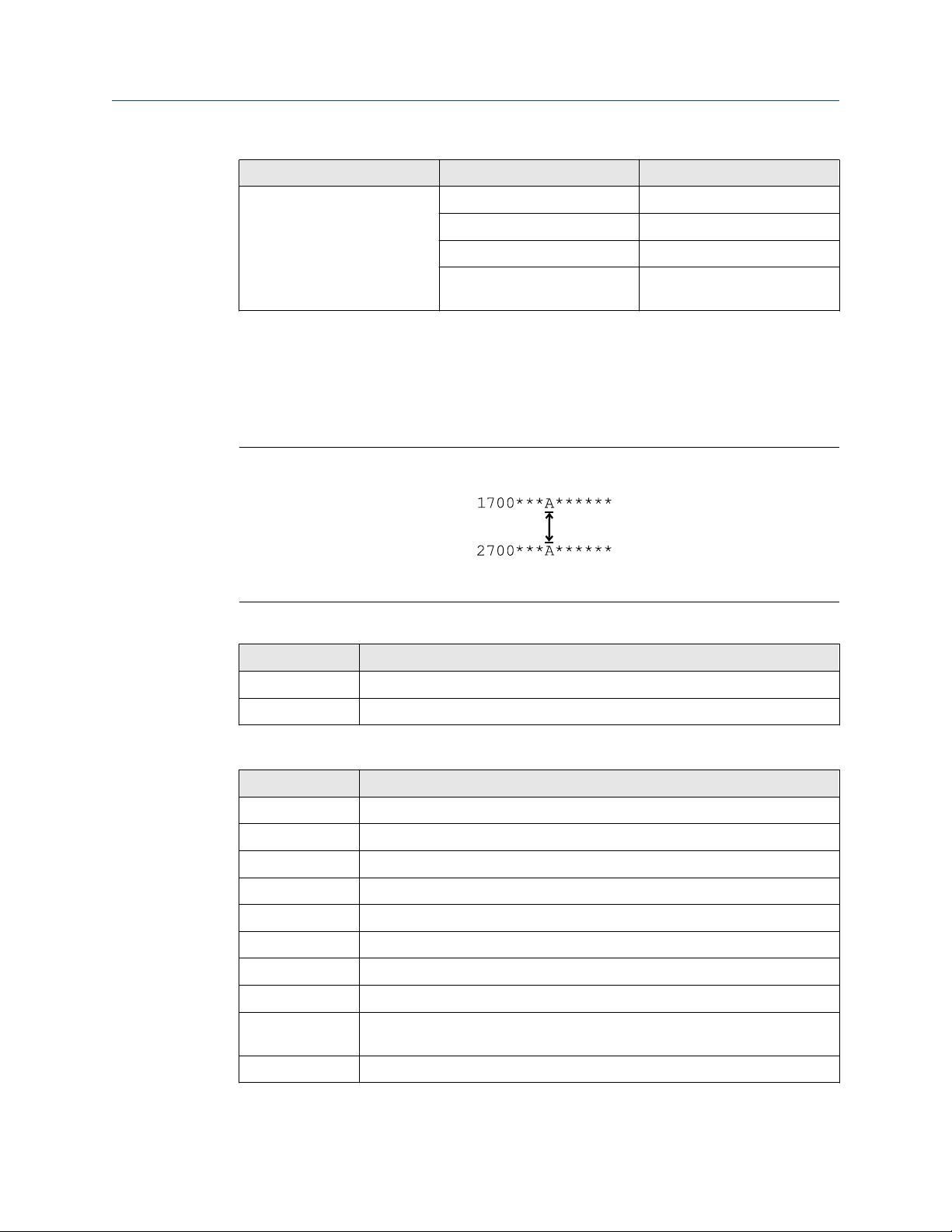
The transmitter was ordered and shipped for one of up to eight installation types. The fifth
character of the transmitter model number indicates the installation type.
Figure 2-1: Installation type indication for 1700 and 2700 transmitters
The model number is located on the device tag on the side of the transmitter.
Table 2-1: Installation types for 1700 and 2700 transmitters
Model code Description
R Remote mount 4-wire
I Integral
E Remote enhanced core processor (painted aluminum housing) with remote
transmitter
C Remote mount 9-wire (painted aluminum housing with integral core)
B Remote core processor with remote transmitter
M Remote mount 4-wire (stainless steel housing)
P Remote mount 9-wire (stainless steel housing)
(1)
H
(1) This option is available only with the 2700 FOUNDATION™ fieldbus transmitter
The transmitter is mounted directly to the sensor. Integral installations do not require
separate transmitter installation. Power supply and I/O must be field wired to the
transmitter.
Remote mount 4-wire (painted aluminum housing) for connecting to
Compact Density Meter (CDM), Fork Density Meter (FDM), Fork Viscosity
Meter (FVM)
Installation Manual 7
Page 8
STATUS
SCROLL SELECT
Planning Installation Manual
December 2019 20001700
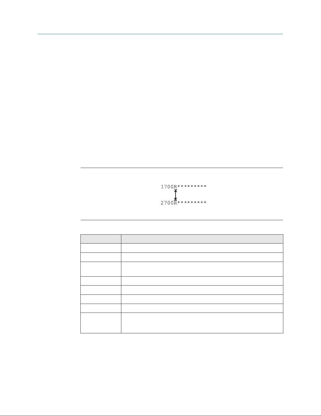
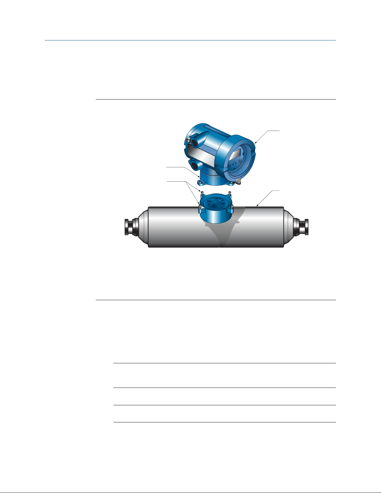
Figure 2-2: Integral installation (model code I)
Note
If replacing an integral 1700/2700 transmitter with a spare transmitter, retain the
transition ring. The replacement does not include a new transition ring.
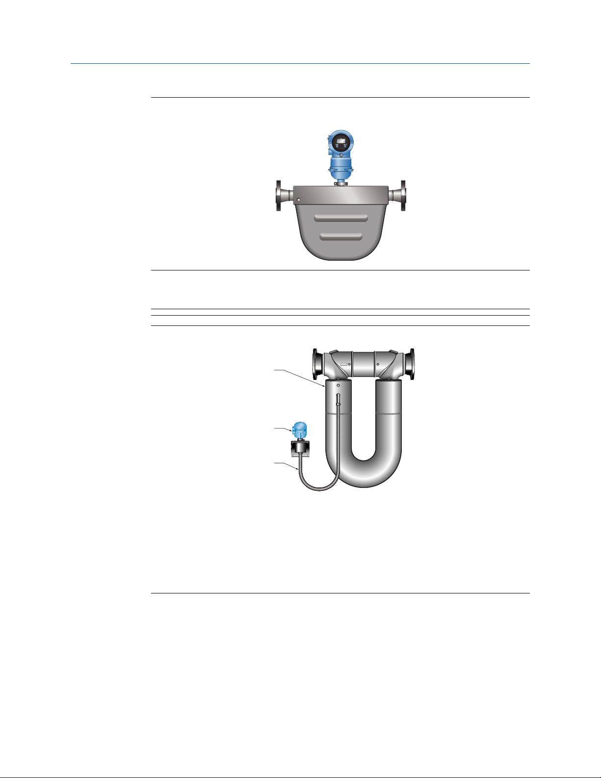
Figure 2-3: High-temperature meters with factory connection (model code I)
A
B
C
The transmitter is shipped with a flexible connection factory installed between the sensor
and the transmitter. The transmitter must be dismounted from its shipping location (spotwelded to the sensor case) and then mounted separately. Power supply and I/O must be
field wired to the transmitter.
A. Sensor
B. Transmitter or core processor
C. Factory-installed flexible connection
8 Micro Motion 1700 and 2700 Transmitters
Page 9

Installation Manual
Planning
20001700 December 2019
Figure 2-4: 4-wire remote installation for Coriolis meters (model code R or M)
A
B
C
D
A
The transmitter is installed remotely from the sensor. The 4-wire connection between the
sensor and transmitter must be field wired. Power supply and I/O must be field wired to
the transmitter.
A. Transmitter
B. Field-wired 4-wire connection
C. Core processor
D. Sensor
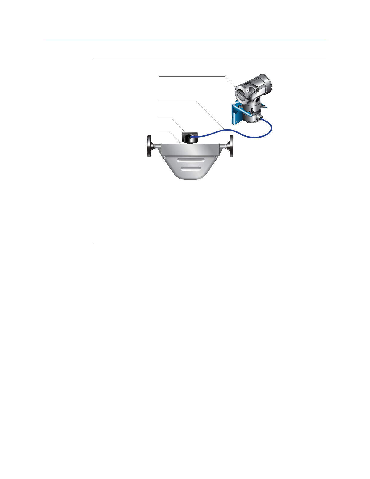
Figure 2-5: 4-wire remote installation for density and viscosity meters (CDM, FDM, or
FVM with fieldbus only model code H)
The transmitter is installed remotely from the Compact Density Meter (CDM), Fork Density
Meter (FDM), or Fork Viscosity Meter (FVM). The 4-wire connection between the sensor
and transmitter must be field wired. Power supply and I/O must be field wired to the
transmitter.
A. Transmitter
B. Field-wired 4-wire connection
C. Meter electronics
Installation Manual 9
Page 10
Planning Installation Manual
December 2019 20001700
Figure 2-6: 9-wire remote installation (model code P)
A
B
C
D
A
The transmitter and core processor are combined in a single unit that is installed remotely
from the sensor. The 9-wire connection between the transmitter/core processor and the
sensor must be field wired. Power supply and I/O must be field wired to the transmitter.
A. Transmitter
B. Field-wired 9-wire connection
C. Junction box
D. Sensor
10 Micro Motion 1700 and 2700 Transmitters
Page 11
Installation Manual Planning
20001700 December 2019
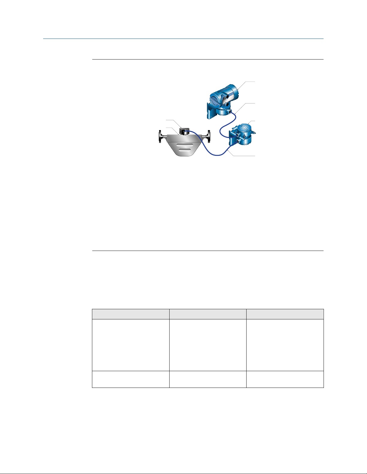
Figure 2-7: Remote core processor with remote sensor installation (model code B or
E)
C
D
A
B
E
F
The transmitter, core processor, and sensor are all mounted separately. The 4-wire
connection between the transmitter and core processor must be field wired. The 9-wire
connection between the core processor and the sensor must be field wired. Power supply
and I/O must be field wired to the transmitter. This configuration is sometimes called
double-hop.
A. Junction box
B. Sensor
C. Transmitter
D. Field-wired 4-wire connection
E. Core processor
F. Field-wired 9-wire connection
2.3 Maximum cable lengths between sensor and transmitter
The maximum cable length between the sensor and transmitter that are separately
installed is determined by cable type.
Cable type
Micro Motion 4-wire remote
mount
Micro Motion 9-wire remote
mount
Installation Manual 11
Wire gauge Maximum length
Not applicable • 1,000 ft (305 m) without
Ex-approval
• 500 ft (152 m) with IIC
rated sensors
• 1,000 ft (305 m) with IIB
rated sensors
Not applicable 60 ft (18 m)
Page 12
Planning Installation Manual
December 2019 20001700
Cable type Wire gauge Maximum length
User-supplied 4-wire VDC 22 AWG (0.326 mm²) 300 ft (91 m)
VDC 20 AWG (0.518 mm²) 500 ft (152 m)
VDC 18 AWG (0.823 mm²) 1,000 ft (305 m)
2.4 Output options
The transmitter was ordered and shipped for one of up to 10 output options. You must
know your transmitter output option to correctly install the transmitter. The eighth
character of the transmitter model number indicates the output option.
Figure 2-8: Output option indication for 1700 and 2700 transmitters
The model number is located on the device tag on the side of the transmitter.
Table 2-2: Output options for 1700 transmitters
Letter Description
A Analog outputs – one mA, one frequency, one RS-485
D Intrinsically safe analog outputs – one mA, one frequency
RS-485 22 AWG (0.326 mm²)
or larger
1,000 ft (305 m)
Table 2-3: Output options for 2700 transmitters
Letter Description
A Analog outputs – one mA, one frequency, one RS-485
B Configurable I/O channels (default configuration of two mA, one frequency)
C Configurable I/O channels (custom configuration )
D Intrinsically safe analog outputs – two mA, one frequency
E Intrinsically safe FOUNDATION fieldbus H1 with standard function blocks
G PROFIBUS-PA
N Non-incendive FOUNDATION fieldbus H1 with standard function blocks
2 WirelessHART® – one mA, one frequency, one RS-485
3 WirelessHART – one mA, two configurable I/O channels (custom
configuration)
4 Intrinsically safe WirelessHART – two mA, one frequency
12 Micro Motion 1700 and 2700 Transmitters
Page 13
Installation Manual Planning
20001700 December 2019
2.5 Electrical connections
Table 2-4: 1700 and 2700 transmitters
Connection type 1700 2700
Input/Output • Intrinsically safe
version: Two pairs
of wiring terminals
for transmitter
outputs
• Non-intrinsically
safe analog
outputs (output
option A): Three
pairs of wiring
terminals for
transmitter
outputs
Power • One pair of wiring terminals accepts AC or DC power
• One internal ground lug for power-supply ground wiring
Service port Two clips for temporary connection to the service port
Three pairs of wiring terminals for transmitter
I/O and communications
Notes
• Each screw terminal connection accepts one or two solid conductors, 14 AWG
(2.08 mm²) to 12 AWG (3.31 mm²) or one or two stranded conductors, 22 AWG
(0.326 mm²) to 14 AWG (2.08 mm²). Each plug type connector accepts one stranded
or solid conductor, 24 AWG (0.205 mm²) to 12 AWG (3.31 mm²).
• For 1700/2700 transmitters with an integral core processor (mounting code C), the 4-
wire connection between the transmitter and core processor is not normally accessed.
2.6 Environmental limits
1700 and 2700
Type
Ambient temperature limits
Humidity limits 5 to 95% relative humidity, non-condensing at
Installation Manual 13
(1)
Value
Operating:
-40 °F (-40.0 °C) to 140 °F (60.0 °C)
Storage:
-40 °F (-40.0 °C) to 140 °F (60.0 °C)
140 °F (60.0 °C)
Page 14

Planning Installation Manual
December 2019 20001700
Type Value
Vibration limits Meets IEC 60068-2-6,endurance sweep, 5 to
2000 Hz up to 1.0 g
Housing rating NEMA 4X [IP66/67/69(K)]
(1) Display responsiveness decreases, and display may become difficult to read below -4 °F
(-20.0 °C). Above 131 °F (55.0 °C), some darkening of display might occur.
(2) The protection is IP69K-based NEN-ISO 20653:2013 and IP69 when using standard IEC/EN
60529.
(2)
2.7 Hazardous area classifications
If you plan to mount the transmitter in a hazardous area:
• Verify that the transmitter has the appropriate hazardous area approval. Each
transmitter has a hazardous area approval tag attached to the housing.
• Ensure that any cable used between the transmitter and the sensor meets the
hazardous area requirements.
2.8 Power requirements
Self-switching AC/DC input, automatically recognizes supply voltage
• 85 to 265 VAC, 50/60 Hz, 6 watts typical, 11 watts maximum
• 18 to 100 VDC, 6 watts typical, 11 watts maximum
• Complies with low voltage directive 2006/95/EC per EN 61010-1 (IEC 61010-1) with
amendment 2, and Installation (Overvoltage) Category II, Pollution Degree 2
Notes
For DC power:
• Power requirements assume a single transmitter per cable.
• At startup, the power source must provide a minimum of 1.5 amps of short-term
current per transmitter.
• Length and conductor diameter of the power cable must be sized to provide 18 VDC
minimum at the power terminals, at a load current of 0.5 amps.
M = 18V + R × L × 0.5A
M: Minimum supply voltage
R: Cable resistance
L: Cable length
Table 2-5: Typical power cable resistance at 68 °F (20.0 °C)
Wire gauge Resistance
14 AWG 0.0050 Ω/ft
16 AWG 0.0080 Ω/ft
14 Micro Motion 1700 and 2700 Transmitters
Page 15

Installation Manual Planning
20001700 December 2019
Table 2-5: Typical power cable resistance at 68 °F (20.0 °C) (continued)
Wire gauge Resistance
18 AWG 0.0128 Ω/ft
20 AWG 0.0204 Ω/ft
2.5 mm
1.5 mm
1.0 mm
0.75 mm
0.50 mm
2
2
2
2
2
0.0136 Ω/m
0.0228 Ω/m
0.0340 Ω/m
0.0460 Ω/m
0.0680 Ω/m
Installation Manual 15
Page 16

Planning Installation Manual
December 2019 20001700
16 Micro Motion 1700 and 2700 Transmitters
Page 17

Installation Manual
20001700 December 2019
Mounting
3 Mounting
3.1 Mounting for integral installations
There are no separate mounting requirements for integral transmitters.
3.2 Orientation
You can mount the transmitter in any orientation as long as the conduit openings do not
point upward.
NOTICE
Upward-facing conduit openings risk condensation moisture entering the transmitter
housing that could damage the transmitter.
3.3 Accessibility for maintenance
Mount the transmitter in a location and orientation that satisfies the following conditions:
• Allows sufficient clearance to open the transmitter housing cover. Micro Motion
recommends 8 in (203 mm) – 10 in (254 mm) clearance at the rear of the transmitter.
• Provides clear access for installing cabling to the transmitter.
3.4 Mounting options
There are two options available for mounting the transmitter:
• Mount the transmitter to a wall or flat surface.
• Mount the transmitter to an instrument pole.
3.4.1
Mount the transmitter to a wall
Prerequisites
• Use two 0.31 in (7.9 mm) U-bolts for a 2 in (51 mm) pipe, and four matching nuts that
can withstand the process environment. Appropriate bolts and nuts are shipped with
remote mount transmitters in the ship kit. The pipe mount kit can be ordered as part of
the 1700/2700 part number.
• Ensure that the surface is flat and rigid, does not vibrate, or move excessively.
• Confirm that you have the necessary tools, and the mounting kit shipped with the
transmitter.
Procedure
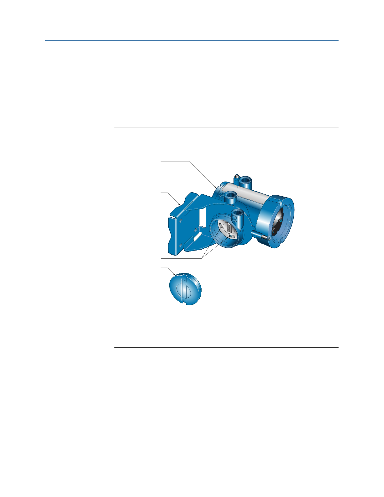
1. If desired, re-orient the transmitter on the mounting bracket.
Installation Manual 17
Page 18
B
D
C
A
Mounting Installation Manual
December 2019 20001700
a) Remove the junction end-cap from the junction housing.
b) Loosen each of the four 0.16 in (4.1 mm) cap screws.
c) Rotate the bracket so that the transmitter is oriented as desired.
d) Tighten the cap screws, torquing to 30 in lbf (3.39 N m) to 38 in lbf (4.29 N
m).
e) Replace the junction end-cap.
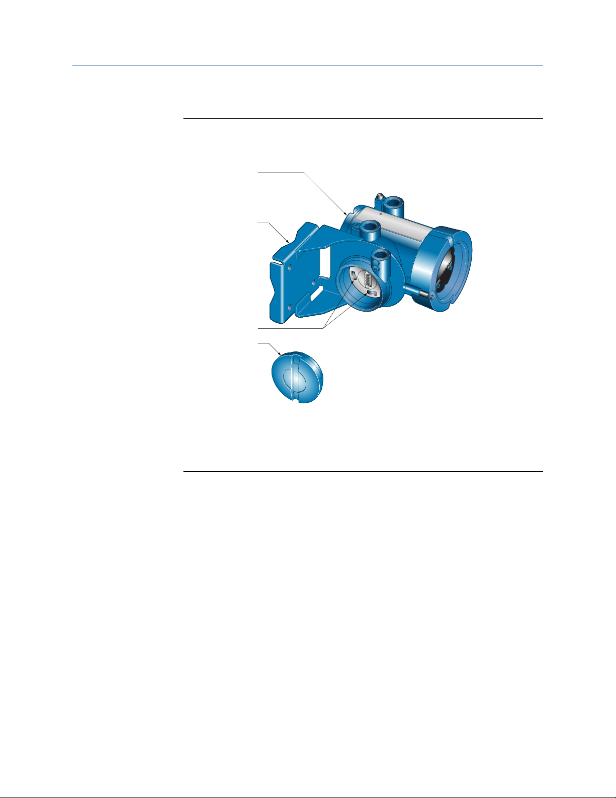
Figure 3-1: Components of 4-wire remote mount transmitter (aluminum
housing)
A. Transmitter
B. Mounting bracket
C. Cap screws
D. End-cap
18 Micro Motion 1700 and 2700 Transmitters
Page 19
Installation Manual Mounting
20001700 December 2019
Figure 3-2: Components of a 4-wire remote mount transmitter (stainless steel
housing)
A. Transmitter
B. Mounting bracket
C. Cap screws
D. End-cap
Installation Manual 19
Page 20
A
B
C
Mounting
December 2019 20001700
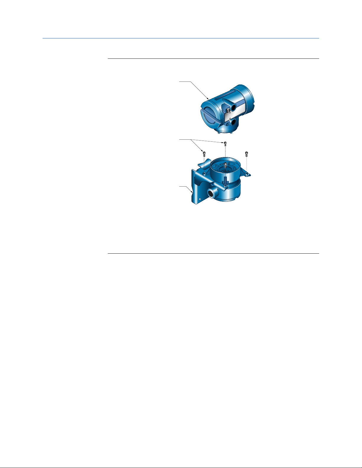
Figure 3-3: Components of 9-wire remote mount transmitter
Installation Manual
A. Transmitter
B. Cap screws
C. Mounting bracket
2. Attach the mounting bracket to the wall.
3.4.2
Mount the transmitter to an instrument pole
Prerequisites
• Use two 0.3125 in (8 mm) U-bolts for 2 in (51 mm) pipe, and four matching nuts, that
can withstand the process environment. Micro Motion does not supply U-bolts or nuts
(appropriate bolts and nuts are available as an option).
• Ensure the instrument pole extends at least 12 in (305 mm) from a rigid base, and is no
more than 2 in (51 mm) in diameter.
Procedure
1. If desired, re-orient the transmitter on the mounting bracket.
a) For 4-wire remote mount transmitters, remove the junction end-cap from
the junction housing.
b) Loosen each of the four 0.16 in (4.1 mm) cap screws.
c) Rotate the bracket so that the transmitter is oriented as desired.
d) Tighten the cap screws, torquing to 30 in lbf (3.39 N m) to 38 in lbf (4.29 N
m).
20 Micro Motion 1700 and 2700 Transmitters
Page 21
B
D
C
A
Installation Manual Mounting
20001700 December 2019
e) If applicable, replace the junction end-cap.
Figure 3-4: Components of 4-wire remote mount transmitter (aluminum
housing)
A. Transmitter
B. Mounting bracket
C. Cap screws
D. End-cap
Installation Manual 21
Page 22

A
B
C
Mounting Installation Manual
December 2019 20001700
Figure 3-5: Components of 9-wire remote mount transmitter
A. Transmitter and integral core
B. Cap screws
C. Mounting bracket
2. Attach the mounting bracket to an instrument pole.
22 Micro Motion 1700 and 2700 Transmitters
Page 23
A
B
C
D
Installation Manual
Mounting
20001700 December 2019
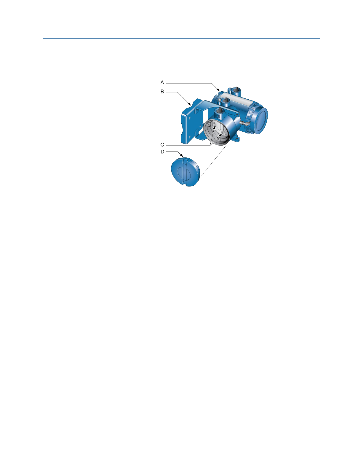
3.5 Rotate the transmitter on the sensor (optional)
In integral installations, you can rotate the transmitter on the sensor up to 360º in 90º
increments.
Figure 3-6: Components of an integral transmitter
A. Transmitter
B. Transition ring
C. Cap screws
D. Sensor
Procedure
1. Loosen each of the four cap screws 0.16 in (4.1 mm) that fasten the transmitter to
the base.
2. Rotate the transmitter counter-clockwise so that the cap screws are in the unlocked
position.
3. Gently lift the transmitter straight up, disengaging it from the cap screws.
NOTICE
Do not disconnect or damage the wires that connect the transmitter to the core
processor.
4. Rotate the transmitter to the desired orientation.
NOTICE
Do not pinch or stress the wires.
The slots on the transition ring should be aligned with the cap screws.
5. Gently lower the transmitter onto the base, inserting the cap screws into the slots.
Installation Manual 23
Page 24
A
B
C
G
E
F
D
Mounting
Installation Manual
December 2019 20001700
6. Rotate the transmitter clockwise so that the cap screws are in the locked position.
7. Tighten the cap screws, torquing to 1.70 ft lbf (2 N m) to 2.51 ft lbf (3 N m).
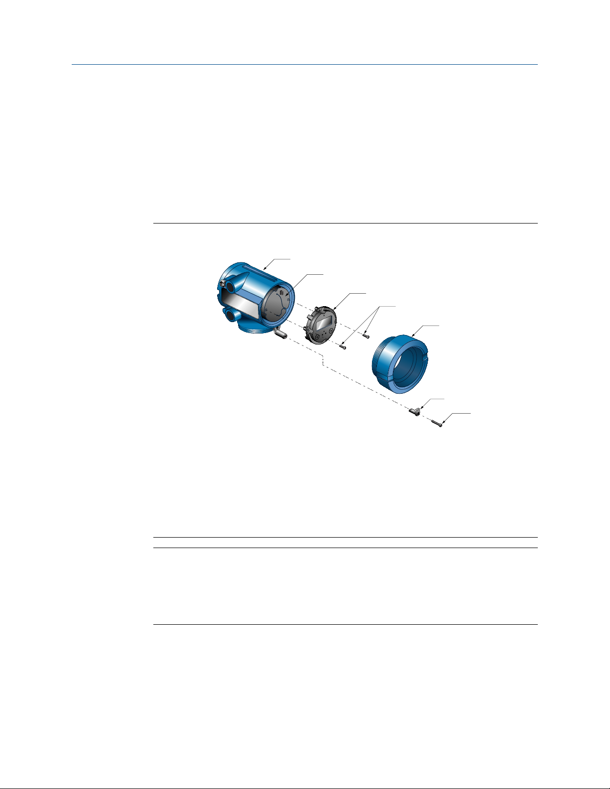
3.6 Rotate the user interface on the transmitter (optional)
The user interface on the transmitter electronics module can be rotated 90º or 180° from
the original position. .
Figure 3-7: Display components
A. Transmitter housing
B. Sub-bezel
C. Display module
D. Display screws
E. End-cap clamp
F. Cap screw
G. Display cover
Notes
• When using the touch buttons, you must cover at least a 0.31 in (7.9 mm) diameter
circle over the surface above the touch button: using your thumb may be more
effective because it has a greater surface area.
• When the housing cover is removed, the touch buttons do not function.
Procedure
1. Shut off power to the unit.
2. Remove the end-cap clamp by removing the cap screw.
3. Turn the display cover counterclockwise to remove it from the main enclosure.
24 Micro Motion 1700 and 2700 Transmitters
Page 25

Installation Manual Mounting
20001700 December 2019
4. Carefully loosen (and remove if necessary) the semicaptive display screws while
holding the display module in place.
5. Carefully pull the display module out of the main enclosure until the sub-bezel pin
terminals are disengaged from the display module.
Note
If the display pins come out of the board stack with the display module, remove the
pins and reinstall them.
6. Rotate the display module to the desired position.
7. Insert the sub-bezel pin terminals into the display module pin holes to secure the
display in its new position.
8. If you have removed the display screws, line them up with the matching holes on
the sub-bezel, then reinsert and tighten them.
9. Place the display cover onto the main enclosure.
10. Turn the display cover clockwise until it is snug.
11. Replace the end-cap clamp by reinserting and tightening the cap screw.
12. Restore power to the transmitter.
Installation Manual 25
Page 26

Mounting Installation Manual
December 2019 20001700
26 Micro Motion 1700 and 2700 Transmitters
Page 27

Installation Manual Preparing the wires
20001700 December 2019
4 Preparing the wires
4.1 Prepare the 4-wire cable
4.1.1 4-wire cable types and usage
Micro Motion offers two types of 4-wire cable: shielded and armored. Both types contain
shield drain wires.
The cable supplied by Micro Motion consists of one pair of red and black 18 AWG
(0.823 mm²) wires for the VDC connection, and one pair of white and green 22 AWG
(0.326 mm²) wires for the RS-485 connection.
User-supplied cable must meet the following requirements:
• Twisted pair construction.
• Applicable hazardous area requirements, if the core processor is installed in a
hazardous area.
• Wire gauge appropriate for the cable length between the core processor and the
transmitter, or the host.
Wire gauge
VDC 22 AWG (0.326 mm²) 300 ft (91 m)
VDC 20 AWG (0.518 mm²) 500 ft (152 m)
VDC 18 AWG (0.823 mm²) 1,000 ft (305 m)
RS-485 22 AWG (0.326 mm²) or larger 1,000 ft (305 m)
Maximum cable length
Prepare a cable with a metal conduit
Procedure
1. Remove the core processor cover using a flat-blade screw driver.
2. Run the conduit to the sensor.
3. Pull the cable through the conduit.
4. Cut the drain wires and let them float at both ends of the conduit.
Prepare a cable with user-supplied cable glands
Procedure
1. Remove the core processor cover using a flat-blade screw driver.
2. Pass the wires through the gland.
3. Terminate the shield and drain wires inside the gland.
4. Assemble the gland according to vendor instructions.
Installation Manual 27
Page 28

Preparing the wires Installation Manual
December 2019 20001700
Prepare a cable with Micro Motion-supplied cable glands
Procedure
1. Remove the core processor cover using a flat-blade screw driver.
2. Pass the wires through the gland nut and clamping insert.
A. Gland nut
B. Clamping insert
3. Strip the cable jacket.
Option Description
NPT gland type Strip 4.5 in (114 mm)
M20 gland type Strip 4.25 in (107.9 mm)
4. Remove the clear wrap and filler material.
5. Strip most of the shielding.
Option
NPT gland type Strip all but 0.75 in (19.0 mm)
M20 gland type Strip all but 0.5 in (13 mm)
6. Wrap the drain wires twice around the shield and cut off the excess drain wires.
A. Drain wires wrapped around shield
7. For foil (shielded cable) only:
Note
For braided (armored cable) skip this step and contine to the next step.
Option
Description
Description
NPT
gland
type
28 Micro Motion 1700 and 2700 Transmitters
a. Slide the shielded heat shrink over the drain wires. Ensure that the
wires are completely covered.
b. Apply heat 250 °F (121.1 °C) to shrink the tubing. Do not burn the
cable.
Page 29

Installation Manual Preparing the wires
20001700 December 2019
Option Description
c. Position the clamping insert so the interior end is flush with the
braid of the heat shrink.
A. Shielded heat shrink
B. After heat is applied
M20
Trim 0.3 in (8 mm).
gland
type
A. Trim
8. Assemble the gland by folding the shield or braid back over the clamping insert and
0.125 in (3.18 mm) past the O-ring.
A. Shield folded back
9. Install the gland body into the conduit opening on the core processor housing.
10. Insert the wires through the gland body and tighten the gland nut onto the gland
body.
A. Shield folded back
B. Gland body
Installation Manual 29
Page 30

Preparing the wires Installation Manual
December 2019 20001700
4.2 Prepare the 9-wire cable
Micro Motion supplies three types of 9-wire cable: jacketed, shielded, and armored. The
type of cable you are using determines how you will prepare the cable.
4.2.1 9-wire cable types and usage
Cable types
Micro Motion supplies three types of 9-wire cable: jacketed, shielded, and armored. Note
the following differences between the cable types:
• Armored cable provides mechanical protection for the cable wires.
• Jacketed cable has a smaller bend radius than shielded or armored cable.
• If ATEX compliance is required, the different cable types have different installation
requirements.
Cable jacket types
All cable types can be ordered with a PVC jacket or Teflon® FEP jacket. Teflon FEP is
required for the following installation types:
• All installations that include a T-series sensor.
• All installations with a cable length of 250 ft (76.20 m) or greater, a nominal flow less
than 20 percent, and ambient temperature changes greater than 68 °F (20.0 °C).
Table 4-1: Cable jacket material and temperature ranges
Cable jacket
material
PVC -4 °F (-20.0 °C) 194 °F (90.0 °C) -40 °F (-40.0 °C) 221 °F (105.0 °C)
Teflon FEP -40 °F (-40.0 °C) 194 °F (90.0 °C) -76 °F (-60.0 °C) 302 °F (150.0 °C)
Cable bend radii
Table 4-2: Bend radii of jacketed cable
Jacket material Outside diameter
PVC 0.415 in (10.54 mm) 3.15 in (80.0 mm) 6.25 in (158.8 mm)
Teflon FEP 0.340 in (8.64 mm) 2.6 in (66 mm) 5.15 in (130.8 mm)
Handling temperature Operating temperature
Low limit High limit Low limit High limit
Minimum bend radii
Static (no load)
condition
Under dynamic load
30 Micro Motion 1700 and 2700 Transmitters
Page 31

A
C (4)
B (4)
D (5)
Installation Manual Preparing the wires
20001700 December 2019
Table 4-3: Bend radii of shielded cable
Minimum bend radii
Jacket material Outside diameter
PVC 0.525 in (13.33 mm) 4.25 in (107.9 mm) 8.5 in (216 mm)
Teflon FEP 0.425 in (10.80 mm) 3.25 in (82.6 mm) 6.38 in (162.1 mm)
Static (no load)
condition
Under dynamic load
Table 4-4: Bend radii of armored cable
Minimum bend radii
Jacket material Outside diameter
PVC 0.525 in (13.33 mm) 4.25 in (107.9 mm) 8.5 in (216 mm)
Teflon FEP 0.340 in (8.64 mm) 3.25 in (82.6 mm) 6.38 in (162.1 mm)
Static (no load)
condition
Under dynamic load
Cable illustrations
Figure 4-1: Cross-section view of jacketed cable
A. Outer jacket
B. Drain wire (4 total)
C. Foil shield (4 total)
D. Filler (5 total)
Installation Manual 31
Page 32

A
C (1)
B
D
E (4)
F (4)
G (5)
A
C (1)
B
D
E (4)
F (4)
G (5)
Preparing the wires Installation Manual
December 2019 20001700
Figure 4-2: Cross-section view of shielded cable
A. Outer jacket
B. Tin-plated copper braided shield
C. Foil shield (1 total)
D. Inner jacket
E. Drain wire (4 total)
F. Foil shield (4 total)
G. Filler (5 total)
Figure 4-3: Cross-section view of armored cable
A. Outer jacket
B. Stainless steel braided shield
C. Foil shield (1 total)
D. Inner jacket
E. Drain wire (4 total)
F. Foil shield (4 total)
G. Filler (5 total)
32 Micro Motion 1700 and 2700 Transmitters
Page 33

Installation Manual Preparing the wires
20001700 December 2019
4.2.2 Prepare jacketed cable
Prepare jacketed cable at sensor end
Procedure
1. Trim 4.5 in (114 mm) of cable jacket.
2. Remove the clear wrap and filler material.
3. Remove the foil that is around the insulated wires and separate them.
A. Trim cable jacket
4. Identify the drain wires in the cable. Clip off each drain wire as close as possible to
the cable jacket.
A. Drain wires clipped
5. Slide the 1.5 in (38 mm) heat-shrink tubing over the wires and cable jacket. The
tubing should completely cover the clipped ends of the drain wires.
A. Heat-shrink tubing
6. Without burning the cable, apply heat to shrink all tubing. Recommended
temperature is 250 °F (121.1 °C).
7. Allow the cable to cool, then strip 0.25 in (6.4 mm) of insulation from each wire.
Prepare jacketed cable at transmitter end
Procedure
1. Trim 4 in (102 mm) of cable jacket.
2. Remove the clear wrap and filler material.
3. Remove the foil that is around the insulated wires and separate them.
A. Trim cable jacket
Installation Manual 33
Page 34

Preparing the wires Installation Manual
December 2019 20001700
4. Identify the drain wires in the cable and bring them together.
5. Fan the other wires to the outside of the cable.
6. Twist the drain wires together.
7. Slide the 3 in (76 mm) heat-shrink tubing over the drain wires. Push the tubing as
close as possible to the cable jacket.
8. Slide the 1.5 in (38 mm) long heat-shrink tubing over the cable jacket. The tubing
should completely cover all portions of the drain wires that remain exposed next to
the cable jacket.
A. Heat-shrink tubing over cable jacket
B. Heat-shrink tubing over drain wires
4.2.3
9. Without burning the cable, apply heat to shrink all tubing. Recommended
temperature is 250 °F (121.1 °C).
10. Allow the cable to cool, then strip 0.25 in (6.4 mm) of insulation from each wire.
Prepare shielded or armored cable
Prepare shielded or armored cable at sensor end
Procedure
1. Without cutting the shield, strip 7 in (178 mm) of outer jacket.
2. Strip 6.5 in (165 mm) of braided shield, so 0.5 in (13 mm) of shield remains
exposed.
3. Remove the foil shield that is between the braided shield and inner jacket.
4. Strip 4.5 in (114 mm) of inner jacket.
A. Trim outer jacket
B. Trim braided shield
C. Trim inner jacket
5. Remove the clear wrap and filler material.
6. Remove the foil that is around the insulated wires and separate them.
34 Micro Motion 1700 and 2700 Transmitters
Page 35

Installation Manual Preparing the wires
20001700 December 2019
7. Identify the drain wires in the cable. Clip each drain wire as close as possible to the
cable jacket.
A. Drain wires clipped
8. Slide the 1.5 in (38 mm) heat-shrink tubing over the cable jacket. The tubing should
completely cover the clipped ends of the drain wires.
A. Heat-shrink tubing
9. Without burning the cable, apply heat to shrink all tubing. Recommended
temperature is 250 °F (121.1 °C).
10. Allow the cable to cool, then strip 0.25 in (6.4 mm) of insulation from each wire.
Prepare shielded or armored cable at transmitter end
Procedure
1. Without cutting the shield, strip 9 in (229 mm) of cable jacket.
2. Strip 8.5 in (216 mm) of braided shield, so 0.5 in (13 mm) of shield remains
exposed.
3. Remove the foil shield that is between the braided shield and inner jacket.
4. Strip 4 in (102 mm) of inner jacket.
A. Trim outer jacket
B. Trim braided shield
C. Trim inner jacket
5. Remove the clear wrap and filler material.
6. Remove the foil that is around the insulated wires and separate them.
7. Identify the drain wires in the cable and bring them together.
8. Fan the other wires to the outside of the cable.
Installation Manual 35
Page 36

Preparing the wires Installation Manual
December 2019 20001700
9. Twist the drain wires together.
10. Slide the 3 in (76 mm) heat-shrink tubing over the drain wires. Push the tubing as
close as possible to the cable jacket.
11. Slide the 1.5 in (38 mm) long heat-shrink tubing over the cable jacket. The tubing
should completely cover all portions of the drain wires that remain exposed next to
the cable jacket.
A. Heat-shrink tubing over cable jacket
B. Heat-shrink tubing over drain wires
12. Without burning the cable, apply heat to shrink all tubing. Recommended
temperature is 250 °F (121.1 °C).
13. Allow the cable to cool, then strip 0.25 in (6.4 mm) of insulation from each wire.
36 Micro Motion 1700 and 2700 Transmitters
Page 37

Installation Manual Wiring the transmitter to the sensor
20001700 December 2019
5 Wiring the transmitter to the sensor
Note
For integral installations, there is no need to connect wiring between the transmitter and
the sensor.
5.1 Wire the transmitter to the sensor (4-wire)
Use this procedure to wire the transmitter to the sensor in a 4-wire remote installation.
Procedure
1. Connect the cable to the sensor-mounted core processor as described in the sensor
documentation.
2. Feed the wires from the sensor through the conduit opening on the transmitter.
3. Connect wires to the appropriate terminals on the mating connector.
Tip
You may find it easier to unplug the mating connector to connect the wires. If you
do so, remember to firmly reseat the mating connector and tighten the mating
connector screws so that the mating connector cannot accidentally come loose.
Figure 5-1: Wiring path for transmitters with aluminum housing
A. 4-wire cable
B. Transmitter conduit opening
C. Mating connector
Installation Manual 37
Page 38

A
B
C
Wiring the transmitter to the sensor Installation Manual
December 2019 20001700
5.2 Wire the transmitter to the remote core processor (4-wire)
Use this procedure to wire the transmitter to the remote core processor in a 4-wire remote
sensor installation. This procedure applies to both 700 and 800 core processors.
Procedure
1. If you are installing a Micro Motion-supplied cable gland at the core processor
housing, identify the cable gland to use for the 4-wire cable conduit opening.
Figure 5-2: Cable gland identification
A. Cable gland used with 4-wire conduit opening
B. ¾ in–14 NPT cable gland used with 9-wire conduit opening
C. ½ in–14 NPT or M20x1.5 cable glands used with transmitter
2. Connect the cable to the core processor as described in the sensor documentation.
3. Feed the wires from the remote core processor through the conduit opening.
4. Connect wires to the appropriate terminals on the mating connector.
Tip
You may find it easier to unplug the mating connector to connect the wires. If you
do so, remember to firmly reseat the mating connector and tighten the mating
connector screws so that the mating connector cannot accidentally come loose.
38 Micro Motion 1700 and 2700 Transmitters
Page 39

Installation Manual Wiring the transmitter to the sensor
20001700 December 2019
Figure 5-3: Wiring path for transmitters with aluminum housing
A. 4-wire cable
B. Transmitter conduit opening
C. Mating connector
Installation Manual 39
Page 40

Wiring the transmitter to the sensor Installation Manual
December 2019 20001700
Figure 5-4: Wiring path for transmitters with stainless steel housing
A. 4-wire cable
B. Transmitter conduit opening
C. Mating connector
5.3 Wire the remote core processor to the sensor using jacketed cable (9-wire)
Use this procedure to wire the remote core processor to the sensor using jacketed cable in
a 9-wire remote sensor installation.
Prerequisites
For ATEX installations, the jacketed cable must be installed inside a user-supplied sealed
metallic conduit that provides 360° termination shielding for the enclosed cable.
WARNING
Sensor wiring is intrinsically safe. To keep sensor wiring intrinsically safe, keep the
sensor wiring separated from power supply wiring and output wiring.
40 Micro Motion 1700 and 2700 Transmitters
Page 41

Installation Manual Wiring the transmitter to the sensor
20001700 December 2019
NOTICE
• Keep cable away from devices such as transformers, motors, and power lines, which
produce large magnetic fields. Improper installation of cable, cable gland, or conduit
could cause inaccurate measurements or flow meter failure.
• Improperly sealed housings can expose electronics to moisture, which can cause
measurement error or flowmeter failure. Install drip legs in conduit and cable, if
necessary. Inspect and grease all gaskets and O-rings. Fully close and tighten all
housing covers and conduit openings.
Procedure
1. Run the cable through the conduit. Do not install 9-wire cable and power cable in
the same conduit.
2. To prevent conduit connectors from seizing in the threads of the conduit openings,
apply a conductive anti-galling compound to the threads, or wrap threads with PTFE
tape two to three layers deep.
Wrap the tape in the opposite direction that the male threads will turn when
inserted into the female conduit opening.
3. Remove the junction box cover and core processor end-cap.
4. At both the sensor and transmitter, do the following:
a) Connect a male conduit connector and waterproof seal to the conduit
opening for 9-wire.
b) Pass the cable through the conduit opening for the 9-wire cable.
c) Insert the stripped end of each wire into the corresponding terminal at the
sensor and transmitter ends, matching by color. No bare wires should remain
exposed.
Also see Sensor and remote core processor/transmitter terminals.
Table 5-1: Sensor and remote core processor terminal designations
Remote core
Wire color Sensor terminal
Black No connection Ground screw (see
Brown 1 1 Drive +
Red 2 2 Drive –
Orange 3 3 Lead length
processor
terminal
note)
Function
Drain wires
compensator/
composite RTD/ID
resistor
Yellow 4 4 Temperature
return
Green 5 5 Left pickoff +
Blue 6 6 Right pickoff +
Installation Manual 41
Page 42

Wiring the transmitter to the sensor Installation Manual
December 2019 20001700
Table 5-1: Sensor and remote core processor terminal designations
(continued)
Remote core
Wire color Sensor terminal
Violet 7 7 Temperature +
Gray 8 8 Right pickoff –
White 9 9 Left pickoff –
d) Tighten the screws to hold the wire in place.
e) Ensure integrity of gaskets, grease all O-rings, then replace the junction-box
and transmitter housing covers and tighten all screws, as required.
processor
terminal
Function
5.4 Wire the remote core processor to the sensor using shielded or armored cable (9-wire)
Use this procedure to wire the remote core processor to the sensor using shielded or
armored cable in a 9-wire remote sensor installation.
Prerequisites
For ATEX installations, shielded or armored cable must be installed with cable glands, at
both the sensor and remote core processor ends. Cable glands that meet ATEX
requirements can be purchased from Micro Motion. Cable glands from other vendors can
be used.
NOTICE
• Keep cable away from devices such as transformers, motors, and power lines, which
produce large magnetic fields. Improper installation of cable, cable gland, or conduit
could cause inaccurate measurements or flow meter failure.
• Install cable glands in the 9-wire conduit opening in the transmitter housing and the
sensor junction box. Ensure that the cable drain wires and shields do not make contact
with the junction box or the transmitter housing. Improper installation of cable or cable
glands could cause inaccurate measurements or flow meter failure.
• Improperly sealed housings can expose electronics to moisture, which can cause
measurement error or flowmeter failure. Install drip legs in conduit and cable, if
necessary. Inspect and grease all gaskets and O-rings. Fully close and tighten all
housing covers and conduit openings.
42 Micro Motion 1700 and 2700 Transmitters
Page 43

A B C D E F
G H I
Installation Manual Wiring the transmitter to the sensor
20001700 December 2019
Procedure
1. Identify the components of the cable gland and cable.
Figure 5-5: Cable gland and cable (exploded view)
A. Cable
B. Sealing nut
C. Compression nut
D. Brass compression ring
E. Braided shield
F. Cable
G. Tape or heat-shrink tubing
H. Clamp seat (shown as integral to nipple)
I. Nipple
2. Unscrew the nipple from the compression nut.
3. Screw the nipple into the conduit opening for the 9-wire cable. Tighten it to one
turn past hand-tight.
4. Slide the compression ring, compression nut, and sealing nut onto the cable. Make
sure the compression ring is oriented so the taper will mate properly with the
tapered end of the nipple.
5. Pass the cable end through the nipple so the braided shield slides over the tapered
end of the nipple.
6. Slide the compression ring over the braided shield.
7. Screw the compression nut onto the nipple. Tighten the sealing nut and
compression nut by hand to ensure that the compression ring traps the braided
shield.
8. Use a 1 in (25 mm) wrench to tighten the sealing nut and compression nut 20 ft lbf
(27.1 N m) to 25 ft lbf (33.9 N m) of torque.
Installation Manual 43
Page 44

A
B
C
E
D
F
G A
Wiring the transmitter to the sensor Installation Manual
December 2019 20001700
Figure 5-6: Cross-section of assembled cable gland with cable
A. Cable
B. Sealing nut
C. Seal
D. Compression nut
E. Braided shield
F. Brass compression ring
G. Nipple
9. Remove the junction box cover and remote core processor end-cap.
10. At both the sensor and remote core processor, connect the cable according to the
following procedure:
a) Insert the stripped end of each wire into the corresponding terminal at the
sensor and remote core processor ends, matching by color. No bare wires
should remain exposed.
Also see Sensor and remote core processor/transmitter terminals.
Table 5-2: Sensor and remote core processor terminal designations
Remote core
Wire color Sensor terminal
Black No connection Ground screw (see
Brown 1 1 Drive +
Red 2 2 Drive –
Orange 3 3 Lead length
Yellow 4 4 Temperature
processor
terminal
notes)
Function
Drain wires
compensator/
composite RTD/ID
resistor
return
Green 5 5 Left pickoff +
Blue 6 6 Right pickoff +
44 Micro Motion 1700 and 2700 Transmitters
Page 45

D
I
H
F
E
A
B
C
G
Installation Manual Wiring the transmitter to the sensor
20001700 December 2019
Table 5-2: Sensor and remote core processor terminal designations
(continued)
Remote core
Wire color Sensor terminal
Violet 7 7 Temperature +
Gray 8 8 Right pickoff –
White 9 9 Left pickoff –
b) Tighten the screws to hold the wires in place.
c) Ensure integrity of gaskets, grease all O-rings, then replace the junction box
cover and remote core processor end-cap and tighten all screws, as required.
processor
terminal
Function
5.5 Sensor and remote core processor/transmitter terminals
This section describes the sensor to remote control processor terminals or the sensor to
transmitter terminals.
Figure 5-7: All ELITE, H-Series, and T-Series sensor, and 2005 or newer F-Series sensor
terminals
A. Violet
B. Yellow
C. Orange
D. Brown
E. White
F. Green
G. Red
H. Gray
I. Blue
Installation Manual 45
Page 46

1
9
8
7
6
5
4
3
2
A
Wiring the transmitter to the sensor Installation Manual
December 2019 20001700
Figure 5-8: All D and DL, and pre-2005 F-Series sensor terminals
Figure 5-9: DT sensor terminals (user-supplied metal junction box with terminal
block)
A. Earth ground
46 Micro Motion 1700 and 2700 Transmitters
Page 47

A
B
I
H
G
F
E
D
C
J
Installation Manual Wiring the transmitter to the sensor
20001700 December 2019
Figure 5-10: Remote core processor/transmitter terminals
A. Brown
B. Violet
C. Yellow
D. Orange
E. Gray
F. Blue
G. White
H. Green
I. Red
J. Ground screw (black)
Installation Manual 47
Page 48

Wiring the transmitter to the sensor Installation Manual
December 2019 20001700
48 Micro Motion 1700 and 2700 Transmitters
Page 49

Installation Manual Grounding
20001700 December 2019
6 Grounding
6.1 Ground the meter components
• In integral installations, all components are grounded together.
• In 4-wire remote installations, the transmitter and sensor are grounded separately.
• In 9-wire remote installations, the transmitter/core processor assembly and sensor are
grounded separately.
• In a remote core processor with remote sensor installation, the transmitter, remote
core processor, and sensor are all grounded separately.
Prerequisites
If national standards are not in effect, adhere to the following guidelines for grounding:
• Use copper wire, 14 AWG (2.08 mm²) or larger wire size.
• Keep all ground leads as short as possible, less than 1 Ω impedance.
• Connect ground leads directly to earth, or follow plant standards.
Procedure
Depending on your installation type:
Option
For an integral
installation
For all other
installations
Description
Ground via the piping if possible (see the sensor documentation). If
grounding via the piping is not possible, ground according to
applicable local standards using the transmitter’s internal or
external ground screw.
a. Ground the sensor according to the instructions in the sensor
documentation.
b. Ground the transmitter according to applicable local
standards, using the transmitter’s internal or external ground
screw.
Installation Manual 49
Page 50

Grounding Installation Manual
December 2019 20001700
Figure 6-1: Transmitter internal grounding screw
Figure 6-2: Transmitter external grounding screw
50 Micro Motion 1700 and 2700 Transmitters
Page 51

A B
C
Installation Manual Wiring the power supply
20001700 December 2019
7 Wiring the power supply
7.1 Wire the power supply
A user-supplied switch may be installed in the power supply line. For compliance with lowvoltage directive 2006/95/EC (European installations), a switch in close proximity to the
transmitter is required.
Procedure
1. Remove the transmitter housing cover.
2. Open the warning flap.
3. Connect the power supply wires to terminals 9 and 10.
Terminate the positive (line) wire on terminal 10 and the return (neutral) wire on
terminal 9.
Figure 7-1: Power supply wiring terminals
A. Warning flap
B. Equipment ground
C. Power supply wiring terminals (9 and 10)
4. Ground the power supply using the equipment ground, also under the warning flap.
Installation Manual 51
Page 52

Wiring the power supply Installation Manual
December 2019 20001700
52 Micro Motion 1700 and 2700 Transmitters
Page 53

A
B
00042
Installation Manual I/O wiring for transmitters with analog outputs
20001700 December 2019
8 I/O wiring for transmitters with
analog outputs
8.1 Basic analog wiring
A. mA Output loop (820 Ω maximum loop resistance)
B. Frequency receiving device (output voltage level is +24 VDC ± 3%, with a 2.2 kΩ pull-up
resistor)
8.2 HART®/analog single loop wiring
Note
For HART communications:
• 600 Ω maximum loop resistance
• 250 Ω minimum loop resistance
Installation Manual 53
Page 54

B
A
B
C
A
RS-485A
RS-485B
I/O wiring for transmitters with analog outputs Installation Manual
December 2019 20001700
A. 820 Ω maximum loop resistance
B. HART-compatible host or controller
8.3 RS-485 point-to-point wiring
A. Other devices
B. Primary controller
C. Multiplexer
54 Micro Motion 1700 and 2700 Transmitters
Page 55

B
A
C
E
D
F
I give up
Installation Manual I/O wiring for transmitters with analog outputs
20001700 December 2019
8.4 HART multidrop wiring
Tip
For optimum HART communication, single-point ground the output loop to an
instrument-grade ground.
A. 250–600 Ω resistance
B. HART-compatible host or controller
C. HART-compatible transmitters
D. 1700 or 2700 transmitter
E. SMART FAMILY™ transmitters
F. 24 VDC loop power supply required for passive transmitters
Installation Manual 55
Page 56

I/O wiring for transmitters with analog outputs Installation Manual
December 2019 20001700
56 Micro Motion 1700 and 2700 Transmitters
Page 57

A
B
A
mA1
mA2
B
Installation Manual I/O wiring for transmitters with intrinsically safe outputs
20001700 December 2019
9 I/O wiring for transmitters with
intrinsically safe outputs
9.1 Safe area mA Output wiring (2700)
A. External DC power supply (VDC)
B. R
load
Installation Manual 57
Page 58

A
mA1
C
B
I/O wiring for transmitters with intrinsically safe outputs Installation Manual
December 2019 20001700
Safe area mA Output load resistance values
R
= (V
max
supply
− 12)/0.023
Minimum 250Ω and 17.5V required for HART communications
A. External resistor R
load
(ohms)
B. Supply voltage VDC (volts)
C. Operating region
9.2 Safe area HART/analog single-loop wiring
A. External DC power supply (VDC)
B. R
(250–600 Ω resistance)
load
C. HART-compatible host or controller
58 Micro Motion 1700 and 2700 Transmitters
Page 59

Installation Manual I/O wiring for transmitters with intrinsically safe outputs
20001700 December 2019
Safe area mA Output load resistance values
R
= (V
max
Minimum 250Ω and 17.5V required for HART communications
A. External resistor R
B. Supply voltage VDC (volts)
C. Operating region
load
(ohms)
supply
− 12)/0.023
9.3 Safe area HART multidrop wiring
Tip
For optimum HART communication, single-point ground the output loop to an
instrument-grade ground.
Installation Manual 59
Page 60

B
A
C
E
D
F
A
B
C
00042
I/O wiring for transmitters with intrinsically safe outputs Installation Manual
December 2019 20001700
A. 250–600 Ω resistance
B. HART-compatible host or controller
C. HART-compatible transmitters
D. 1700 or 2700 transmitter with intrinsically safe outputs
E. SMART FAMILY transmitter
F. 24 VDC loop power supply required for HART 4–20 mA passive transmitters
9.4 Safe area Frequency Output/Discrete Output wiring
A. External DC power supply (VDC)
B. Counter
C. R
load
60 Micro Motion 1700 and 2700 Transmitters
Page 61

Installation Manual I/O wiring for transmitters with intrinsically safe outputs
20001700 December 2019
Safe area Frequency Output/Discrete Output load resistance values
R
= (V
max
R
min
supply
= (V
supply
Minimum 100Ω for supply voltage less than 25.6 volts
A. External pull-up resistor R
range (ohms)
load
B. Supply voltage VDC (volts)
C. Operating region
9.5 Hazardous area wiring
Information provided about I.S. barriers is intended as an overview. Application-specific or
product-specific questions should be addressed to the barrier manufacturer or
Micro Motion.
WARNING
• Hazardous voltage can cause severe injury or death. Shut off the power before wiring
transmitter outputs.
• Improper wiring in a hazardous environment can cause an explosion. Install the
transmitter only in an area that complies with the hazardous classification tag on the
transmitter.
Table 9-1: Safety parameters
− 4)/0.003
− 25)/0.006
Parameter 4–20 mA Frequency/discrete
Voltage (Ui) 30 V 30 V
Current (Ii) 300 mA 100 mA
Power (Pi) 1.0 W 0.75 W
Installation Manual 61
Page 62

I/O wiring for transmitters with intrinsically safe outputs Installation Manual
December 2019 20001700
Table 9-1: Safety parameters (continued)
Parameter 4–20 mA Frequency/discrete
Capacitance (Ci) 0.0005 μF 0.0005 μF
Inductance (Li) 0.0 mH 0.0 mH
Voltage
Current
Capacitance
Inductance
The transmitter’s safety parameters require the selected barrier’s opencircuit voltage to be limited to less than 30 VDC (V
= 30 VDC). This
max
voltage is the combination of the maximum safety barrier voltage
(typically 28 VDC) plus an additional 2 VDC for HART communications
when communicating in the hazardous area.
The transmitter’s safety parameters require the selected barrier’s shortcircuit currents to sum to less than 300 mA (I
milliamp outputs and 100 mA (I
= 100 mA) for the frequency/discrete
max
= 300 mA) for the
max
output.
The capacitance (Ci) of the transmitter is 0.0005 μF. This value added to
the wire capacitance (C
) must be lower than the maximum allowable
cable
capacitance (Co) specified by the I.S. barrier. Use the following equation to
calculate the maximum length of the cable between the transmitter and
the barrier: C
+ C
i
cable
≤ C
o
The inductance (Li) of the transmitter is 0.0 mH. This value plus the field
wiring inductance (L
), must be lower than the maximum allowable
cable
inductance (Lo) specified by the I.S. barrier. The following equation can
then be used to calculate the maximum cable length between the
transmitter and the barrier: L
+ L
i
cable
≤ L
o
62 Micro Motion 1700 and 2700 Transmitters
Page 63

Installation Manual I/O wiring for transmitters with intrinsically safe outputs
20001700 December 2019
9.5.1 Hazardous area mA Output wiring
A. Hazardous area
B. Safe area
C. V
in
D. V
out
E. Ground
F. R
load
G. R
barrier
Note
Add R
load
and R
to determine Vin.
barrier
Installation Manual 63
Page 64

I/O wiring for transmitters with intrinsically safe outputs Installation Manual
December 2019 20001700
Safe area mA Output load resistance values
R
= (V
max
supply
− 12)/0.023
Minimum 250Ω and 17.5V required for HART communications
A. External resistor R
load
(ohms)
B. Supply voltage VDC (volts)
C. Operating region
64 Micro Motion 1700 and 2700 Transmitters
Page 65

Installation Manual I/O wiring for transmitters with intrinsically safe outputs
20001700 December 2019
9.5.2 Hazardous area Frequency Output/Discrete Output wiring using a galvanic isolator
A. Hazardous area
B. Safe area
C. External power supply
D. V
out
E. R
load
F. Galvanic isolator (see note)
G. Counter
Note
The galvanic isolator shown here has an internal 1000 Ω resistor used for sensing current:
• ON > 2.1 mA
• OFF < 1.2 mA
These current switching levels comply with DIN19234 (NAMUR)/DIN EN 60947-5-6/IEC
60947-5-6.
Installation Manual 65
Page 66

I/O wiring for transmitters with intrinsically safe outputs Installation Manual
December 2019 20001700
9.5.3 Hazardous area Frequency Output/Discrete Output wiring using barrier with external load resistance
A. Hazardous area
B. Safe area
C. R
barrier
D. V
in
E. V
out
F. Counter
G. R
load
H. Ground
Note
Add R
barrier
and R
to determine Vin.
load
66 Micro Motion 1700 and 2700 Transmitters
Page 67

Installation Manual I/O wiring for transmitters with intrinsically safe outputs
20001700 December 2019
Safe area Frequency Output/Discrete Output load resistance values
R
= (V
max
R
min
= (V
supply
supply
− 4)/0.003
− 25)/0.006
Minimum 100Ω for supply voltage less than 25.6 volts
A. External pull-up resistor R
range (ohms)
load
B. Supply voltage VDC (volts)
C. Operating region
Installation Manual 67
Page 68

I/O wiring for transmitters with intrinsically safe outputs Installation Manual
December 2019 20001700
68 Micro Motion 1700 and 2700 Transmitters
Page 69

Installation Manual I/O wiring for 2700 with configurable input/outputs
20001700 December 2019
10 I/O wiring for 2700 with configurable
input/outputs
10.1 Channel configuration
The six wiring terminals are divided into three pairs, and called Channels A, B, and C.
• Channel A = terminals 1 and 2
• Channel B = terminals 3 and 4
• Channel C = terminals 5 and 6
Variable assignments are governed by channel configuration.
Table 10-1: Channel configuration
Channel Terminals Configuration options Power
A 1, 2 mA Output with HART/Bell202 Internal
B 3, 4 mA Output (default) Internal
Frequency Output Internal or external
Discrete Output Internal or external
C 5, 6 Frequency Output (default) Internal or external
Discrete Output Internal or external
Discrete Input Internal or external
Notes
• For Channel A, the Bell 202 signal is superimposed on the mA Output.
• You must provide power to the outputs when a channel is set to external power.
• When both Channel B and Channel C are configured for Frequency Output (dual pulse),
Frequency Output 2 is generated from the same signal that is sent to the first
Frequency Output. Frequency Output 2 is electrically isolated but not independent.
• You cannot configure the combination of Channel B as Discrete Output and Channel C
as Frequency Output.
Installation Manual 69
Page 70

A
mA1
mA2
B
I/O wiring for 2700 with configurable input/outputs Installation Manual
December 2019 20001700
10.2 Basic mA Output wiring
A. 820 Ω maximum loop resistance
B. 420 Ω maximum loop resistance
10.3 HART/analog single loop wiring
Note
For HART communications:
• 600 Ω maximum loop resistance
• 250 Ω minimum loop resistance
70 Micro Motion 1700 and 2700 Transmitters
Page 71

B
A
B
A
C
E
D
F
I give up
Installation Manual I/O wiring for 2700 with configurable input/outputs
20001700 December 2019
A. 820 Ω maximum loop resistance
B. HART-compatible host or controller
10.4 HART multidrop wiring
Tip
For optimum HART communication, single-point ground the output loop to an
instrument-grade ground.
A. 250–600 Ω resistance
B. HART-compatible host or controller
C. HART-compatible transmitters
D. 2700 configurable I/O transmitter (internally powered outputs)
E. SMART FAMILY transmitters
F. 24 VDC loop power supply required for HART 4–20 mA passive transmitters
Installation Manual 71
Page 72

A
00042
I/O wiring for 2700 with configurable input/outputs Installation Manual
December 2019 20001700
10.5 Internally powered Frequency Output wiring on Channel B
A. Counter
Output voltage versus load resistance
Maximum output voltage = 15 VDC ± 3%
A. High level output voltage (volts)
B. Load resistance (ohms)
72 Micro Motion 1700 and 2700 Transmitters
Page 73

A
B
C
000042
Installation Manual I/O wiring for 2700 with configurable input/outputs
20001700 December 2019
10.6 Externally powered Frequency Output wiring on Channel B
A. Pull-up resistor
B. External DC power supply (3–30 VDC)
C. Counter
NOTICE
Exceeding 30 VDC can damage the transmitter. Terminal current must be less than 500
mA.
Recommended pull-up resistor versus supply voltage
A. External pull-up resistor range (ohms)
Installation Manual 73
B. Supply voltage (volts)
Page 74

A
00042
I/O wiring for 2700 with configurable input/outputs Installation Manual
December 2019 20001700
10.7 Internally powered FO wiring on Channel C
Figure 10-1: Internally powered FO wiring on Channel C
A. Counter
Maximum output voltage = 15 VDC ± 3%
A. High level output voltage (volts)
B. Load resistance (ohms)
74 Micro Motion 1700 and 2700 Transmitters
Page 75

A
B
C
000042
Installation Manual I/O wiring for 2700 with configurable input/outputs
20001700 December 2019
10.8 Externally powered Frequency Output wiring on Channel C
A. Pull-up resistor
B. External DC power supply (3–30 VDC)
C. Counter
NOTICE
Exceeding 30 VDC can damage the transmitter. Terminal current must be less than 500
mA.
Recommended pull-up resistor versus supply voltage
A. External pull-up resistor range (ohms)
Installation Manual 75
B. Supply voltage (volts)
Page 76

A
I/O wiring for 2700 with configurable input/outputs Installation Manual
December 2019 20001700
10.9 Internally powered Discrete Output wiring on Channel B
A. Total load
Output voltage versus load resistance
Maximum output voltage = 15 VDC ± 3%
A. High level output voltage (volts)
B. Load resistance (ohms)
76 Micro Motion 1700 and 2700 Transmitters
Page 77

B
A
Installation Manual I/O wiring for 2700 with configurable input/outputs
20001700 December 2019
10.10 Externally powered Discrete Output wiring on Channel B
A. External DC power supply (3–30 VDC)
B. Pull-up resistor or DC relay
NOTICE
Exceeding 30 VDC can damage the transmitter. Terminal current must be less than 500
mA.
Recommended pull-up resistor versus supply voltage
A. External pull-up resistor range (ohms)
B. Supply voltage (volts)
Installation Manual 77
Page 78

A
I/O wiring for 2700 with configurable input/outputs Installation Manual
December 2019 20001700
10.11 Internally powered Discrete Output wiring on Channel C
A. Total load
Output voltage versus load resistance
Maximum output voltage = 15 VDC ± 3%
A. High level output voltage (volts)
B. Load resistance (ohms)
78 Micro Motion 1700 and 2700 Transmitters
Page 79

B
A
Installation Manual I/O wiring for 2700 with configurable input/outputs
20001700 December 2019
10.12 Externally powered Discrete Output wiring on Channel C
A. External DC power supply (3–30 VDC)
B. Pull-up resistor or DC relay
NOTICE
Exceeding 30 VDC can damage the transmitter. Terminal current must be less than 500
mA.
Recommended pull-up resistor versus supply voltage
Installation Manual 79
A. External pull-up resistor range (ohms)
B. Supply voltage (volts)
Page 80

A
B
A
C
I/O wiring for 2700 with configurable input/outputs Installation Manual
December 2019 20001700
10.13 Internally powered Discrete Input wiring
A. Switch
10.14 Externally powered Discrete Input wiring
A. PLC or other device
B. Bipolar negative-positive-negative (NPN) transistor
C. Direct DC input
Power is supplied by either a PLC/other device or by direct DC input.
Table 10-2: Input voltage ranges for external power
VDC Range
3–30 High level
0–0.8 Low level
0.8–3 Undefined
80 Micro Motion 1700 and 2700 Transmitters
Page 81

A
B
D
C
E
Installation Manual I/O wiring for 2700 with F
20001700 December 2019
OUNDATION fieldbus or PROFIBUS-PA
11 I/O wiring for 2700 with FOUNDATION
fieldbus or PROFIBUS-PA
11.1 FOUNDATION fieldbus wiring
See the following wiring diagram, and refer to the FOUNDATION fieldbus wiring
specification.
Important
The transmitter is either FISCO or FNICO approved. For FISCO-approved transmitters, a
barrier is required.
Figure 11-1: FOUNDATION fieldbus wiring diagram
A. Bus power supply
B. FOUNDATION fieldbus network per FOUNDATION fieldbus wiring specification
C. Spur to network per FOUNDATION fieldbus wiring specification
D. Terminals 1 and 2
E. Terminals 3 – 6 (unused)
Note
The fieldbus communication terminals (1 and 2) are not polarity-sensitive.
11.2 PROFIBUS-PA wiring
See the following wiring diagram, and refer to the PROFIBUS-PA User and Installation
Guideline published by PNO.
Important
• The transmitter is FISCO approved.
• For intrinsically safe wiring, see the PROFIBUS-PA User and Installation Guideline.
Installation Manual 81
Page 82

A
B
D
C
E
I/O wiring for 2700 with FOUNDATION fieldbus or PROFIBUS-PA Installation Manual
December 2019 20001700
Figure 11-2: PROFIBUS-PA wiring diagram
A. Bus power supply
B. PROFIBUS-PA segment per PROFIBUS-PA User and Installation Guideline
C. Spur to PROFIBUS-PA segment per PROFIBUS-PA User and Installation Guideline
D. Terminals 1 and 2
E. Terminals 3 – 6 (unused)
Note
The PROFIBUS communication terminals (1 and 2) are not polarity-sensitive.
82 Micro Motion 1700 and 2700 Transmitters
Page 83

Installation Manual
20001700 December 2019
Installation Manual 83
Page 84

*20001700*
20001700
Rev. CG
2019
Micro Motion Inc. USA
Worldwide Headquarters
7070 Winchester Circle
Boulder, Colorado USA 80301
T +1 303-527-5200
T +1 800-522-6277
F +1 303-530-8459
www.emerson.com
Micro Motion Asia
Emerson Automation Solutions
1 Pandan Crescent
Singapore 128461
Republic of Singapore
T +65 6363-7766
F +65 6770-8003
©
2019 Micro Motion, Inc. All rights reserved.
The Emerson logo is a trademark and service mark of Emerson Electric Co. Micro Motion, ELITE,
ProLink, MVD and MVD Direct Connect marks are marks of one of the Emerson Automation
Solutions family of companies. All other marks are property of their respective owners.
Micro Motion Europe
Emerson Automation Solutions
Neonstraat 1
6718 WX Ede
The Netherlands
T +31 (0) 318 495 555
T +31 (0) 70 413 6666
F +31 (0) 318 495 556
www.emerson.com/nl-nl
Micro Motion United Kingdom
Emerson Automation Solutions
Emerson Process Management Limited
Horsfield Way
Bredbury Industrial Estate
Stockport SK6 2SU U.K.
T +44 0870 240 1978
F +44 0800 966 181
 Loading...