

Page 1

Instruction Manual
Form 5733
July 2004
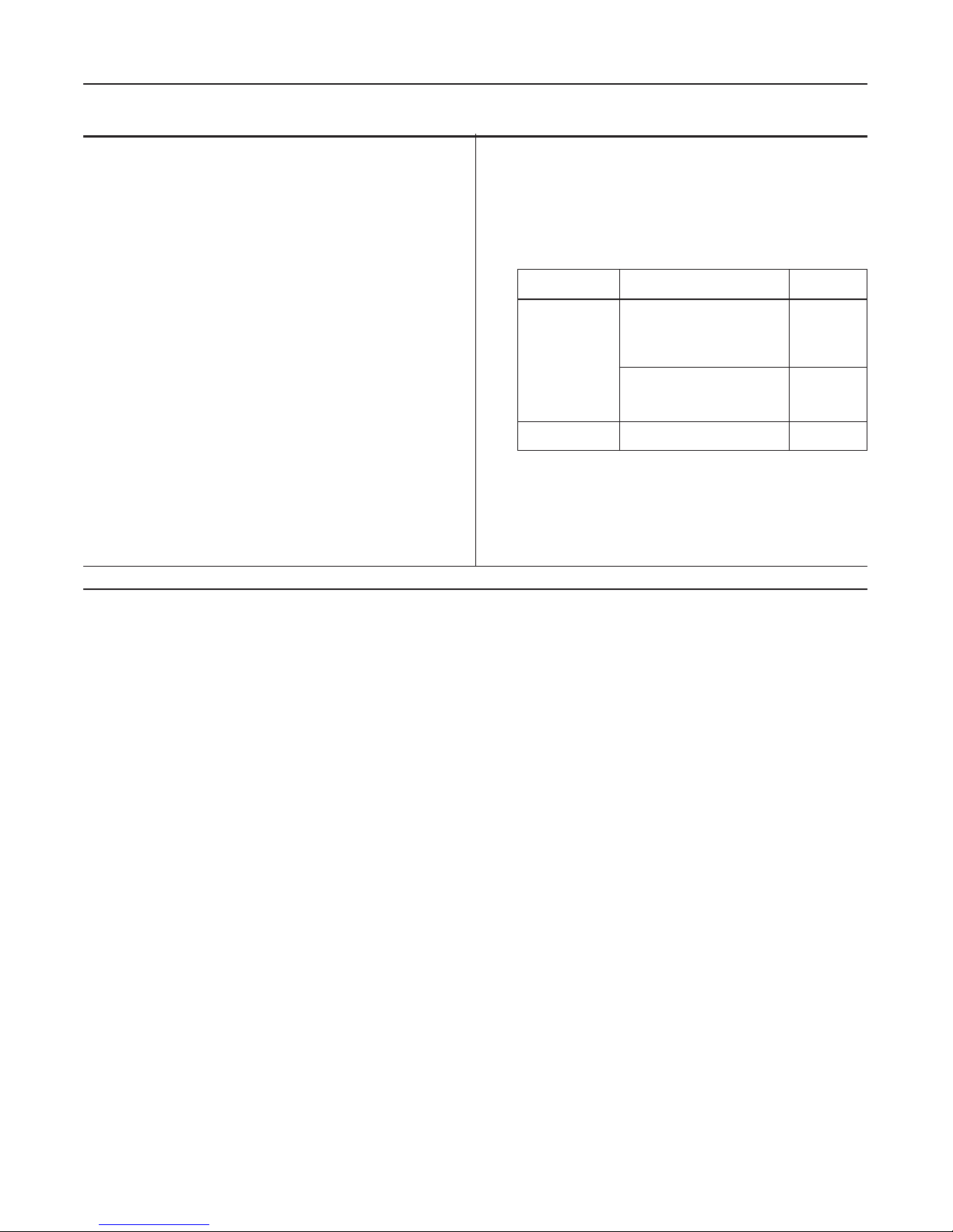
FL Series Pressure Reducing Regulators
E0821
E0820
FL Series
Type FL
Figure 1. T ype FL and T ype MFL with T ype SRS Silencer
Introduction
Scope of Manual
This manual provides instructions for installation,
adjustment, maintenance, and parts ordering for the FL
Series regulators.
Description
The FL Series regulators are accurate pilot-operated,
pressure balanced, soft seated regulators designed for
high pressure transmission/city gate, large capacity
distribution systems and power plant feeds. The FL
Series provides smooth, quiet operation, tight shutoff and
long life. The regulator utilizes a main valve actuator , a
Type PRX pressure reducing pilot, and a Type SA/2 pilot
Type MFL with Type SRS Silencer
supply pressure regulator. The T ype PRX pilot uses inlet
pressure reduced by a Type SA/2 supply pressure
regulator, as loading pressure to operate the main valve
actuator. The outlet pressure is sensed through a
control line on the main valve actuator and also on the
Type PRX pilot diaphragm.
Specifications
The Specifications section gives some general specifications for the FL Series regulators. The nameplates
give detailed information for a particular regulator as it
comes from the factory .
D103068X012
www.FISHERregulators.com
Page 2
FL Series
EPYT
ERUSSERPTELTUO
(GISP,EGNARrab)
GNIRPS
ROLOC
021/XRP
521/XRP
61ot3.7
62ot5.41
44ot32
08ot14
321ot37
)1,1ot5,0(
)
8,1ot1(
)3ot6,1(
)5,5ot8,2(
)5,8ot5(
etihW
wolleY
neerG
eulB
kcalB
012ot611
433ot302
534ot913
906ot124
)5,41ot8(
)3
2ot41(
)03ot22(
)24ot92(
revliS
dloG
munimulA
deR
PA-021/XRP
PA-521/XRP
0611ot534)08ot03(raelC
Specifications
Available Configurations
FL: Pilot-operated pressure reducing regulator
for medium to high outlet pressures
MFL: Monitor and regulator combined into a single
unit for overpressure protection
Maximum Emergency (Design Pressure)
1450 psig (100 bar)
Miminum Operating Differential Pressure
7.3 psid (0,5 bar d)
Outlet Pressure Ranges
Body Sizes
FL and MFL:
1, 1-1/2, 2, 2-1/2, 3, 4, and 6-inch (DN 25, 40, 50, 65,
80, 100, and 150) (6-inch for FL only)
FL and MFL with SRS Silencer (inlet x outlet):
1 x 4, 1-1/2 x 6, 2 x 6, 2-1/2 x 8, 3 x 10, 4 x 10, and
6 x 12-inch (DN 25 x 100, 40 x 150, 50 x 150,
65 x 200, 80 x 250, 100 x 250, and 150 x 300)
(6 x 12-inch for FL only)
Main Valve End Connection Style and Pressure
Ratings
Maximum Inlet and Outlet (Casing) Pressure
(1)
ANSI Class 300 RF: 740 psig (51,0) bar
ANSI Class 600 RF: 1450 psig (100) bar
(1)
1450 psig (100 bar)
1. The pressure/temperature limits in this instruction manual or any applicable standard limitation should not be exceeded.
Pressure Registration
External
Maximum Temperature Capabilities
–20° to 150°F (–29° to 66°C)
(1)
Principle of Operation
The pilot-operated T ype FL (figure 2) uses inlet pressure as the operating medium, which is reduced
through pilot operation to load the actuator diaphragm.
Outlet or downstream pressure opposes loading
pressure in the actuator and also opposes the pilot
control spring.
When outlet pressure drops below the setting of the
pilot control spring, pilot control spring force on the pilot
diaphragm thus opens the pilot valve plug, providing
additional loading pressure to the actuator diaphragm.
This diaphragm loading pressure opens the main valve
plug, supplying the required flow to the downstream
system. Any excess loading pressure on the actuator
diaphragm escapes downstream through the bleed
restriction in the pilot.
When the gas demand in the downstream system has
been satisfied, the outlet pressure increases. The
increased pressure is transmitted through the downstream control line and acts on the pilot diaphragm. This
pressure exceeds the pilot spring setting and moves the
diaphragm, closing the orifice. The loading pressure
acting on the main diaphragm bleeds to the downstream
system through a bleed restriction in the pilot.
2
Adjustment
The adjustment of the regulator is performed by means
of the pilot adjusting screw, which varies the compression of the control spring. Adjustment is performed while
the regulator is in operation with the aid of a test pressure gauge of suitable range or of a water column. The
shutoff valve downstream of the regulator must not be
completely closed; it is necessary that a small quantity
of gas flows downstream to allow the outlet side to vent
down, when it is necessary to lower the pressure.
Loosen the locknut and turn the adjusting screw slowly to
adjust outlet pressure. Use a pressure gauge to check
the outlet pressure until the desired pressure is reached.
Monitoring Systems
Monitoring regulation is overpressure protection by
containment, therefore, there is no relief valve to vent to
the atmosphere. When the working regulator fails to
control the pressure, a monitor regulator installed in
series, which has been sensing the downstream and
control pressure, goes into operation to maintain the
downstream pressure at a slightly higher than normal
pressure. During an overpressure situation, monitoring
Page 3

E0827
INLET PRESSURE
OUTLET PRESSURE
LOADING PRESSURE
PILOT SUPPLY PRESSURE
A TMOSPHERIC PRESSURE
FL Series
Figure 2. T ype FL Operational Schematic
keeps the customer on line. Also, testing is relatively
easy and safe. To perform a periodic test on a monitoring regulator, increase the outlet set pressure of the
working regulator and watch the outlet pressure to
determine if the monitoring regulator takes over at the
appropriate outlet pressure.
Wide-Open Monitoring Systems (figure 3)
There are two types of wide-open monitoring systems:
upstream and downstream. The difference between
upstream and downstream monitoring is that the
functions of the regulators are reversed. Systems can
be changed from upstream to downstream monitoring,
and vice-versa, by simply reversing the setpoints of the
two regulators. The decision to use either an upstream
or downstream monitoring system is largely a matter of
personal preference or company policy .
In normal operation of a wide-open configuration, the
working regulator controls the system’s outlet pressure. With a higher outlet pressure setting, the monitor
regulator senses a pressure lower than its setpoint and
tries to increase outlet pressure by going wide-open. If
the working regulator fails, the monitoring regulator
assumes control and holds the outlet pressure at its
outlet pressure setting.
Working Monitoring Regulators (figure 3)
In a working monitoring system, the upstream regulator
requires two pilots and it is always the monitoring
regulator. The additional pilot permits the monitoring
regulator to act as a series regulator to control an
intermediate pressure during normal operation. In this
way , both units are always operating and can be easily
checked for proper operation.
In normal operation, the working regulator controls the
outlet pressure of the system. The monitoring
regulator’s working pilot controls the intermediate
pressure and the monitoring pilot senses the system’s
outlet pressure. If the working regulator fails, the
monitoring pilot will sense the increase in outlet
pressure and take control.
Note
The working regulator must be rated for
the maximum allowable operating
pressure of the system because this will
be its inlet pressure if the monitoring
regulator fails. Also, the outlet pressure
rating of the monitoring pilot, and any
other components that are exposed to
3
Page 4
FL Series
the intermediate pressure must be rated
for full inlet pressure.
Working monitor installations require a T ype FL main
valve with a Type PRX/120 or PRX/120-AP working pilot
and a T ype PRX/125 or PRX/125-AP monitoring pilot for
the upstream regulator and a Type FL with the appropriate T ype PRX/120 or PRX/120-AP pilot for the downstream regulator. The Type MFL incorporates the
monitor and regulator into one compact unit.
Installation and Startup
Personal injury or equipment damage,
due to bursting of pressure-containing
parts may result if this regulator is overpressured or is installed where service
conditions could exceed the limits given
in the Specification section and on the
appropriate nameplate, or where conditions exceed any rating of the adjacent
piping or piping connections.
To avoid such injury or damage, provide
pressure-relieving or pressure-limiting
devices to prevent service conditions from
exceeding those limits. Also, check that
the installation is in compliance with all
applicable codes and regulations.
Additionally, physical damage to the
regulator could break the pilot off the
main valve, causing personal injury and
property damage due to bursting of
pressure-containing parts. T o avoid such
injury and damage, install the regulator in
a safe location.
Single Pilot Regulator
Installation
A T ype FL regulator bleeds no gas to atmosphere
during normal operation, thus making the regulator
suitable for installation in pits and other enclosed
locations without elaborate venting systems. This
regulator also can be installed in pits subject to
flooding by venting the pilot spring case above the
expected flood level so that the pilot setting can be
referenced to atmospheric pressure.
1. Use qualified personnel when installing, maintaining, or operating this regulator. Inspect the regulator
and the pipeline to be certain both are free of foreign
materials.
2. Install the regulator so that the flow arrow cast on
the main valve matches the flow direction of process
fluid through the regulator.
3. Apply pipe compound to the male pipeline threads
before installing a regulator with screwed end connections. Use gaskets between pipeline and regulator
flanges when installing a regulator with flanged end
connections.
A regulator may vent some gas to the
atmosphere. In hazardous or flammable
gas service, vented gas may accumulate, causing personal injury, death, or
property damage due to bursting of
pressure-retaining parts. Vent a regulator in hazardous gas service to a remote, safe location away from air
intakes or any hazardous location. The
vent line or stack opening must be
protected against condensation or
clogging.
4. A T ype PRX pilot has a 1/4-inch NPT vent connection in the spring case. To remotely vent gas from the
spring case, remove the screened vent, and connect
1/4-inch piping or tubing to the spring case connection.
The piping or tubing should vent to a safe location, have
as few elbows as possible, and have a screened vent
on its exhaust. Install the regulator and any remote
vent piping or tubing so that the vent is protected from
condensation, freezing, or any substance that could
clog it.
5. Connect a pilot supply line from the upstream
piping to the 1/4-inch NPT pilot inlet.
6. Connect a downstream control line to a straight
run of pipe 6 to 10 pipe diameters from the regulator
outlet as shown in figure 3. If such a distance is not
practical, connect the control line away from elbows,
swages, nipples, or any area where abnormal flow
velocities occur.
7. Install a hand valve in the control line.
8. Install the other end of the downstream control
line to the 1/2-inch NPT connection in either side of the
case body.
4
Page 5

TYPE PRX/120 OR
PRX/120-AP
FL Series
TYPE SA/2
TYPE SA/2
B
L
S
A
Single Pilot System Installation
TYPE PRX/120 OR
PRX/120-AP
B
L
S
A
4 x A
B
A
6 x A
TYPE PRX/120 OR
PRX/120-AP
L
S
A
TYPE SA/2
TYPE SA/2
E0825
TYPE PRX/125 OR
PRX/125-AP
B
4 x A
Upsteam or Downstream Wide-Open Monitoring System Installation
TYPE PRX/120 OR
PRX/120-AP
L
A
B
L
S
S
A
TYPE PRX/120 OR
B
L
S
A
PRX/120-AP
4 x A
6 x A
Working Monitoring System Installation
A
6 x A
A
Figure 3. Installation Drawings
5
Page 6

FL Series
9. Consult the appropriate instruction manual for
installation of an optional pneumatic or electric remote
control-drive unit. For optional remote pneumatic loading
of a Type PRX pilot, make the spring case piping
connections just as they would be made for remote
venting.
Prestartup Considerations
Each regulator is factory-set for the outlet pressure
specified on the order. If no setting was specified,
outlet pressure was factory-set at the mid-range of the
pilot control spring. Before beginning the startup
procedure in this section, make sure the following
conditions are in effect:
• Block valves isolate the regulator
• Vent valves are closed
• A bypass, if any, is in operation
In all cases, check the control spring setting to make
sure it is correct for the application.
ing screw counterclockwise decreases the spring
compression and pressure setting.
Pilot Adjustment
T o adjust a st andard Type PRX pilot, loosen the
locknut, and turn the adjusting screw. Then tighten the
locknut to maintain the adjustment position.
Startup
1. Open the upstream block (isolating) valve. Open
hand valve A in the external pilot supply line before
opening the downstream isolating valve (see figure 3).
2. Open the downstream block (isolating) valve for
minimum flow .
3. Slowly open hand valve B in the downstream
control line, while at the same time adjusting the pilot
setting, if necessary.
4. Completely open the downstream block valve.
5. Slowly close the bypass valve, if any .
Pilot supply pressure must be introduced into the regulator before introduction of any downstream pressure, or
internal damage may occur due to
reverse pressurization of the pilot and
main valve components.
Pressure gauges should always be used
to monitor downstream pressure during
startup. Procedures used in putting this
regulator into operation must be
planned accordingly if the downstream
system is pressurized by another regulator or by a manual bypass.
Note
Pilot supply pressure must be at least 15
psig (1,0 bar) greater than control pressure to operate the regulator at rated
travel.
Although remote loading or control constructions may
require separate adjustments on associated equipment,
the only adjustment normally necessary on a
Type FL-PRX regulator is the pressure setting of the
pilot control spring. Turning the adjusting screw
clockwise into the spring case increases the spring
compression and pressure setting. Turning the adjust-
Wide-Open Monitor Regulator
Installation
1. For both the wide-open monitoring regulator and
the working regulator, perform the Single Pilot Regulator Installation procedures through step 9.
2. Connect the control line of a wide-open monitoring
regulator (figure 3) to downstream piping near the
working regulator control line connection. During
normal operation the wide-open monitoring regulator
stands wide open with the pressure reduction being
taken across the working regulator . Only in case of
working regulator failure does the wide-open monitoring
regulator take control at its slightly higher setting.
Prestartup Considerations
Each regulator is factory-set for the outlet pressure
specified on the order. If no setting was specified,
outlet pressure was factory-set at the mid-range of the
pilot control spring. Before beginning the startup
procedures in this section, make sure the following
conditions are in effect:
• Block valves isolate the regulator
• Vent valves are closed
6
Page 7

FL Series
• Hand valves are closed
• A bypass, if any, is in operation
In all cases, check the control spring setting to make
sure it is correct for the application.
Introduce pilot supply pressure into the
regulator before introducing any downstream pressure, or internal damage
may occur due to reverse pressurization
of the pilot and main valve components.
Always use pressure gauges to monitor
downstream pressure during startup. If
the downstream is pressurized by
another regulator, plan startup procedures accordingly .
Note
Pilot supply pressure must exceed
control pressure by at least 15 psig
(1,0 bar) in order to operate the regulator at rated travel.
Although remote loading or control constructions may
require separate adjustments on associated equipment,
the only adjustment normally necessary on a
Type FL-PRX regulator is the pressure setting of the
pilot control spring. Turning the adjusting screw
clockwise into the spring case increases the spring
compression and pressure setting. Turning the adjusting screw counterclockwise decreases the spring
compression and pressure setting.
Pilot Adjustment
T o adjust a st andard Type PRX pilot, loosen the
locknut, and turn the adjusting screw. Then tighten the
locknut to maintain the adjustment position.
Startup
3. Slowly open the hand valve in the control line
while, at the same time, adjusting the pilot setting if
necessary.
4. Completely open the downstream block valve.
5. Slowly close the bypass valve, if any .
Working Monitor Regulator
Installation
All T ype FL working monitor regulators are bench set at
the factory according to the service conditions specified
on the customer’s order. Examine the unit on arrival to
make sure no damage has occurred in shipment. Clean
and blow out pipelines to be sure no welding slag or
other foreign material is present.
Install the T ype FL into the pipeline using adequate
gaskets for flanged regulator units and good piping
technique. Be sure to provide suitable pressure gauges
where appropriate, block valves, bypass valves and
piping, and bleed valves to permit safe and easy
maintenance of both the working monitor regulator and
the second-stage working regulator. Be sure flow will be
in the direction indicated by the arrow cast on the body
Refer to the figure 3 schematic and figure 4, and
proceed in the following steps.
1. Attach the intermediate pressure control line
(1/2-inch NPT pipe) between the 1/2-inch NPT pipe tee
and the intermediate pressure portion of the downstream piping. Install hand valve B in this line.
2. Connect 1/2-inch NPT distribution pressure
control line piping between the 1/2-inch NPT connection in the mounting bracket and the pipeline downstream of the second-stage working regulator . Include
hand valve A in this control line.
Note
Each pilot has a nameplate identifying it
as the working or monitor pilot.
This procedure is to be repeated in turn for each
regulator in the installation.
1. Slowly open the hand valve in the pilot supply line.
2. Slowly open the upstream block (isolating) valve
and partially open the downstream block valve for
minimum flow .
3. Pipe the pilot supply line to 1/4-inch NPT connection in the back of the working pilot body . Supply
pressure should be filtered if excess dirt or condensate
is present in the supply gas.
4. Install downstream working regulator per guidelines.
7
Page 8

FL Series
Startup
1. Before introducing any pressure to the unit, close
hand valve A in the distribution pressure control line and
hand valve B in the intermediate pressure control line.
Pilot supply pressure must be introduced into the regulator prior to introduction of any downstream pressure or
internal damage may occur due to
reverse pressurization of the pilot and
main valve components. Pilot supply
pressure must be at least 15 psi (1,0 bar)
greater than control pressure for proper
operation.
2. Slowly open the hand valve in the pilot supply line.
3. Slowly open the upstream block valve and partially
open the downstream block valve for minimum flow.
4. Slowly open hand valve B and allow the intermediate pressure to increase to the working pilot setting.
5. Put the second-stage working regulator into
operation according to recommended procedures and
instructions furnished with the second-stage working
regulator.
3. Adjust the second-stage working regulator to the
desired distribution pressure by following instructions
for that particular regulator .
4. Adjust the setting of the monitoring pilot to
establish the desired emergency distribution pressure,
which is to be maintained in the event of failure of the
second-stage working regulator . The steps followed
may vary with each piping situation. The basic method
remains the same.
The following procedure serves as an example which
can be used or modified to make monitoring pilot
adjustments in any installation.
Increase the outlet pressure setting of the secondstage working regulator until the monitoring pilot takes
control of the distribution pressure. Adjust the monitoring pilot setting until the desired emergency distribution
pressure is achieved. Refer to table 2 for the recommended minimum differential between the monitoring
pilot setting and the desired distribution pressure.
With settings as desired on both the monitoring and
the working pilots, tighten the locknuts to maintain
proper adjustment screw positions. Then re-adjust the
second-stage working regulator to the desired distribution pressure.
Shutdown
6. After the distribution pressure has been estab-
lished slowly open hand valve A.
Pilot Adjustment
The second-stage working regulator must be set to
operate at a lower pressure than the monitoring pilot or
the monitoring pilot will try to take control of the
distribution pressure. Follow the steps listed to obtain
the desired results.
1. Increase the setting of the monitoring pilot by
loosening the locknut and turning the adjusting screw
clockwise (into the spring case cap) until the working
pilot is in control of the intermediate pressure and the
second-stage working regulator is in control of the
distribution pressure.
2. Adjust the setting of the working pilot by loosening the jam nut and turning the adjusting screw clockwise (into the spring case cap) to increase the intermediate pressure, or counterclockwise (out of the spring
case cap) to reduce the intermediate pressure. Adjust
until desired intermediate pressure is reached.
In any installation it is important to slowly open and
close the valves and to vent the outlet pressure before
venting the inlet pressure to prevent damage caused by
reverse pressurization of the pilot or main valve.
Single Pilot Regulators and Wide-Open
Monitor Regulators
As well as applying to a single-pilot regulator, the steps
in this procedure also are valid for a wide-open monitoring installation and should be repeated for each regulator in such an installation.
1. Close the upstream isolating valve.
2. Close block valve A in the supply line.
3. Close the downstream isolating valve.
4. If the downstream control line taps into the
pipeline above the downstream isolating valve,
open vent valve C between the regulator and the
downstream isolating valve. Permit all pressure to
bleed out of the regulator.
8
Page 9

FL Series
If the downstream control line taps into the pipeline below the downstream isolating valve, close
hand valve B. Then open vent valve C and vent valve D,
permitting all pressure to bleed out of the regulator.
5. Open vent valve E to release any inlet pressure
that may be trapped in the regulator.
Working Monitor Regulators
1. Close the upstream isolating valve.
2. Close hand valve in pilot supply line.
3. Close the downstream isolating valve.
4. Open a bleed valve between the second-stage
working regulator and the downstream isolating valve.
Permit all pressure to bleed out of the working monitor
regulator and the second-stage working regulator.
5. Open vent valve to vent any intermediate pressure
trapped in the system.
6. Open vent valve to release any inlet pressure
trapped in the regulator.
Maintenance
The regulator parts are subject to normal wear and must
be inspected periodically and replaced as necessary.
The frequency of inspection and replacement depends
on the severity of service conditions and on applicable
federal, state and local codes and regulations.
4. Reinstall the pad.
Main Valve Diaphragm Maintenance
1. Place main valve with inlet side up.
2. Remove the travel indicator assembly by removing
the indicator cover (key 40) and indicator bushing
(key 38). Check O-ring (key 37), replace if necessary .
Remove the indicator support (key 36). Check O-ring
(key 35), replace if necessary . Lif t out indicator stem
assembly (keys 33 and 34).
3. Remove inlet flange (key 1) by removing socket
head cap screws (key 5). Due to force created by the
spring (key 6), take care when removing inlet flange.
Check O-rings (keys 3 and 4) and anti-friction rings
(key 2), replace if necessary.
4. Lift out spring (key 6). Remove hex head cap
screws, washers, and nuts (keys 9, 14, and 15). Lift
off the inlet cover (key 1 1). Check O-ring (key 3) and
anti-friction rings (key 2), replace if necessary .
5. Remove diaphargm assembly by removing screws
(key 27) to separate the outlet and the inlet plates
(keys 12 and 8). Check diaphragm (key 10) and O-rings
(keys 26 and 28) for damage and replace if necessary .
Check sleeve (key 16) seating surface for damage.
6. Reassemble in reverse order.
PRX Pilot Maintenance
To avoid personal injury or property
damage from sudden release of pressure, isolate the regulator from the
pressure system, and release all pressure
from the pilot and main valve before
performing maintenance operations.
Main Valve
Main Valve Pad Replacement
1. Remove outlet flange (key 22) by removing socket
head cap screws (key 5).
2. Remove pad holder assembly and O-ring (key 18).
3. Remove pad (key 20) from pad holder (key 19) by
removing cap screw (key 25) and pad retainer (key 21),
replace pad if necessary .
Always remove spring (key 7) tension
before performing maintenance on this
unit. T o remove spring tension, loosen
locknut (key 2) and back out adjusting
screw (key 1) until compression is
removed from the spring.
Lower Case Maintenance
1. Disconnect pilot and remove it from the line.
2. Remove screws (key 10) from lower cover (key 21)
and the separate lower cover from the body (key 16).
3. Use a wrench to hold the stem (key 23) and break
loose the stem nut (key 20). Remove the stem nut and
washer (key 1 1).
4. Remove the diaphragm plate (key 13), diaphragm
(key 14), pad holder (key 22), and O-ring (key 18).
9
Page 10

FL Series
Inspect the parts for damage or wear , and replace if
necessary.
5. Remove orifice (key 19) and O-ring (key 17).
Inspect the parts for damage or wear , and replace if
necessary . Lightly lubricate the O-ring and place in the
body (key 16). Install the orifice.
6. Set the pad holder (key 22) in the body (key 16).
7. Lightly lubricate the rims of the diaphragm (key 14)
and place it on top of the pad holder (key 22). Set the
diaphragm plate (key 13) on the diaphragm (key 14).
8. Lightly lubricate the O-ring (key 18) and place it in
the lower case (key 21).
9. Place the washer (key 1 1) and stem nut (key 20)
on the stem (key 23) and tighten.
If also performing
Upper Case Maintenance, skip to step 2 of the Upper
Case Maintenance section.
10. Insert machine screws (key 10) in the lower cover
(key 21) and tighten uniformly to ensure proper seal.
Upper Case Maintenance
1. Disconnect pilot and remove it from the line.
2. Loosen locknut (key 2) and back out adjusting
screw (key 1) until compression is removed from the
spring. Remove cap (key 3).
3. Lift the spring carrier (key 6), spring (key 7), and
O-ring (key 4) out of the upper cover (key 8). Inspect
O-ring and replace if necessary .
4. Remove machine screws (key 10) from lower cover
(key 21) and the separate lower cover from the body
(key 16), unless removed during lower diaphragm
maintenance. Use a wrench to hold stem (key 19)
securely while removing the stem nut (key 26).
5. Remove remaining loose components: washer ,
upper diaphragm plate, diaphragm, lower diaphragm
plate, and O-rings (keys 11, 13, 14, 15, 18, and 25).
Inspect diaphragm and O-rings for damage or wear, and
replace if necessary .
6. Lightly lubricate the O-ring (key 25). Place O-ring
over the stem (key 19) and press it down into the body
(key 16).
7. Set the lower diaphragm plate (key 15) into the
body (key 16).
9. Set the upper diaphragm plate (key 13) on top of
the diaphragm (key 14).
10. Place washer (key 1 1) and stem nut (key 26) on
the stem (key 19) and tighten using a wrench to hold
the stem.
1 1. Set the spring carrier (key 6).
Damper and Restrictor Maintenance
1. Remove screw (key 31) and plate (key 29).
2. Remove ring nuts (key 30).
3. Remove damper adjusting screw (key 27). Remove
and inspect O-ring (key 28) for damage or wear, and
replace if necessary . Lightly lubricate O-ring before
placing on the adjusting screw. Insert damper adjusting screw into the body (key 16) and tighten. Insert
ring nut (key 30) and tighten. Back out damper
adjusting screw until it stops.
4. Remove restrictor adjusting screw with hole
(key 32). Remove and inspect O-ring (key 28) for
damage or wear, and replace if necessary . Lightly
lubricate O-ring before placing on the adjusting screw.
Insert restrictor adjusting screw into the body (key 16)
and completely tighten. Insert ring nut (key 30) and
completely tighten. Back out restrictor adjusting screw
1/2 turn.
Note
When using a Type PRX/120 pilot with a
Type PRX/125 pilot as a monitor, use the
following settings:
• restrictor - completely tighten and
then back out three full turns.
• damper - back out until it stops.
5. Install plate (key 29) and screw (key 31).
T ype SA/2
1. Disconnect pilot supply filter regulator and remove
it from the line.
2. Remove bolts, washers, and nuts (keys 2, 9, and 10)
from body (key 16) and the separate upper and lower
covers (keys 1 1 and 19) from the body (key 16). When
separating the covers from the body , be aware of loose
components: (keys 1, 3, 4, 8, 12, 18, 20, and 21).
8. Lightly lubricate the rims of the diaphragm (key 14)
and place it in the body (key 16) on top of the lower
diaphragm plate (key 15).
10
3. Remove and inspect O-ring (key 13) for damage or
wear, and replace if necessary. Lightly lubricate the
O-ring before placing it back in the (key 1 1).
Page 11

FL Series
4. Clean screens (key 8). Replace filter pad (key 12).
5. Inspect diaphragm (key 18) for damage or wear,
and replace if necessary . Check the seating surface of
the (key 17) for erosion, scratches, spurs, or other
damage, and replace if necessary .
6. Unscrew and remove (key 5). Inspect O-ring
(key 6) for damage or wear, and replace if necessary .
Lightly lubricate the O-ring and place it on (key 5).
7. Pull (key 15) out of the body (key 16). Inspect the
seat for damage, and replace if necessary .
8. Set the (key 15) on the spring (key 14) and insert
the (key 5). Tighten the (key 5) until it stops.
9. Lightly lubricate the outer and inner rims of the
diaphragm (key 18). Place the diaphragm assembly on
top of the (key 5). The (key 17) will slide into (key 5).
Use care to avoid damage to parts when reassembling.
10. Set the spring (key 1) on top of the (key 21).
1 1. Align the (key 19) over the body (key 16) with the
sense port (V) opposite the pilot supply port (R).
12. Place the filter pad (key 12) and screens (key 8),
one on each side of the filter pad, on the (key 1 1).
13. Pick up the body (key 16) and place it on the
(key 1 1) with the inlet port (M) aligned vertically with the
sense port (V).
14. Insert bolts (key 2). Place washers (key 9) and
nuts (key 10) on the end of the bolts. Tighten the nuts.
Parts Ordering
Refer to the T ype number when contacting your Fisher
Sales Office or Sales Representative for technical
information. When ordering parts, also be sure to
include the complete 1 1-character part kit number .
Parts List
FL Main V alve (figure 4)
Key Description
Part Kit (includes key number: 2, 3, 4, 10, 18,
20, 26, 28, 35, 38, 46, and 47) See Table
1 Inlet Flange
2* Anti-Friction Ring
3* O-Ring
4* Body O-Ring
5 Screw
6 Spring
7 Fitting
8 Inlet Plate
9 Screw
10* Diaphragm
11 Inlet Cover
12 Outlet Plate
13 Outlet Cover
14 Washer
15 Nut
16 Sleeve
17 Fitting
18* O-Ring
19 Pad Holder
20* Pad
21 Pad Retainer
22 Outlet Flange
23 Gasket
24 Disassembly Spacer
25 Screw
26* O-Ring
27 Screw
28* O-Ring
29 Metal Plate
30 Nameplate Sticker
31 Drive Screw
32 Flow Arrow
33 Spring Collet
34 Indicator
35* O-Ring
36 Support
37 Indicator Bushing
38* O-Ring
39 Indicator Label
40 Indicator Cover
43 SR Silencer
46* O-Ring
47* O-Ring
48 Washer
M ATERIAL
NITRILE GD89984X012 GD89977X012 GD89985X012 GD89975X012 GD89986X012 GD89987X012 GD89988X012 ~
VITON GD89984X022 GD89977X022 GD89985X022 GD89975X022 GD89986X022 GD89987X022 GD89988X022 ~
NITRILE SR-SRS GD89973X012 GD89976X012 GD89972X012 GD89974X012 GD89971X012 GD89970X012 GD89969X012 ~
VITON SR-SRS GD89973X022 GD89976X022 GD89972X022 GD89974X022 GD89971X022 GD89970X022 GD89969X022 ~
~ CALL FOR KIT NUMBER
1 (DN 25) 1-1/2 (DN 40) 2 (DN 25) 2-1/2 (DN 65) 3 (DN 80) 4 (DN 100) 6 (DN 150) 8 (DN 200)
* Indicates Recommended Spare.
FL Series Parts Kit Part Numbers
SIZE, IN C H ES (D N )
11
Page 12

FL Series
12
Figure 4. FL Assembly
Page 13

FL Series
SRS Main V alve (figure 5)
Key Description
23 Gasket
24 Flange Spacer
200 Body
201 Retainer
202 Stud
203 Atenuator Plate
204 Spring Pin
205 Flange
206 Nut
207 Atenuator Plate
208 Atenuator Plate
209 Spacer
210 Spring Cage
211 Spring
Figure 5. SRS Assembly
13
Page 14

FL Series
TYPE PRX/120 OR PRX/125
TYPE PRX/120-AP OR PRX/125-AP
TYPE PRX/120 OR PRX/125 TYPE PRX/120-AP OR PRX/125-AP
14
Figure 6. PRX Series Pilot Assembly
Page 15

PRX Series Pilots (figure 6)
Description Part Number
Elastomer Parts Kits (includes keys: 4, 5, 14, 17,
18, 25, and 28)
Types PRX/120 and PRX/125
Nitrile GD89982X012
Fluoroelastomer GD89982X022
Types PRX/120-AP and PRX/125-AP
Nitrile GD89982X012
Fluoroelastomer GD89982X022
Key Description
1 Adjusting Screw
2 Lockut
3 Cap
(1)
4
Upper Cover O-Ring
(1)
5
O-Ring
6 Spring Carrier Plate
7 Spring (See table 2)
8 Upper Cover
9 Spring Carrier Plate
10 Machine Screw
11 Washer
12 Filter
13 Diaphragm Plate
(1)
14
Diaphragm
15 Diaphragm Plate
16 Body
(1)
17
Orifice O-Ring
(1)
18
Lower Cover O-Ring
19 Orifice
20 Nut
21 Lower Cover
22 Pad Holder
23 Stem
24 Nameplate
26 Upper Diaphragm Nut
27 Damper Adjusting Screw
(1)
28
Restrictor/Damper O-Ring
29 Plate
30 Ring Nut
31 Damper/Restrictor Screw
32 Restrictor Adjusting Screw with Hole
33 Plug
34 Plug
FL Series
T ype SA/2 Pilot Supply Filter Regulator
(figure 7)
Description Part Number
Elastomer Parts Kits (includes keys: )
Nitrile GD89995X012
Fluoroelastomer GD89995X022
Key Description
1 Spring
2 Socket Head Cap Screw
3 Washer
4 Plate
5 Regulator Seat
6 O-ring
7 Body
8 Filter Net
9 Washer
10 Nut
1. Recommended Spare Part
Figure 7. Type SA/2 Assembly
Key Description
11 Filter Cover
12 Felt
13 O-Ring
14 Spring
15 Pad Holder Unit
16 Nameplate
17 Screw Unit
18 Diaphragm
19 Regulator Cover
20 Spring Washer
21 Nut
15
Page 16

FL Series
Fisher is a mark owned by Fisher Controls International, Inc., a business of Emerson Process Management. The Emerson logo is a trade mark and service mark of Emerson Electric Co. All other marks are the
property of their respective owners.
The contents of this publication are presented for informational purposes only, and while every effort has been made to ensure their accuracy, they are not to be construed as warranties or guarantees, express
or implied, regarding the products or services described herein or their use or applicability. We reserve the right to modify or improve the designs or specifications of such product s at any time without notice.
Fisher does not assume responsibility for the selection, use or maintenance of any product. Responsibility for proper selection, use and maintenance of any Fisher product remains solely with the purchaser.
For information, contact Fisher:
Marshalltown, Iowa 50158 USA
McKinney, Texas 75070 USA
28320 Gallardon, France
40013 Castel Maggiore (BO), Italy
Sao Paulo 05424 Brazil
Singapore 128461
©Fisher Controls International, Inc., 2002, 2004; All Rights Reserved
www.FISHERregulators.com
 Loading...