

Page 1
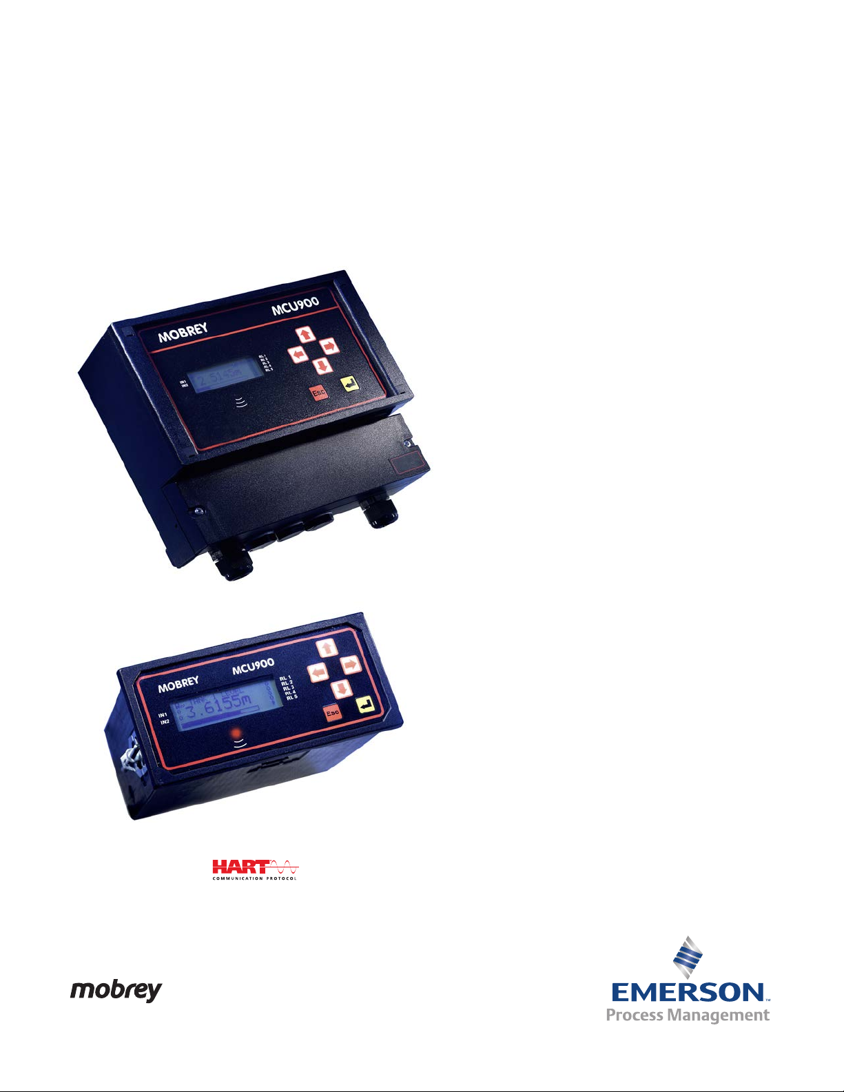
Mobrey MCU900 Series
4–20 mA + HART® Compatible Controller
Reference Manual
IP2030/RM, Rev AA
June 2014
Page 2

Page 3

Reference Manual
IP2030/RM, Rev AA
Title Page
June 2014
Mobrey MCU900 Series
Universal Control Unit
Read this manual before working with the product.
For personal and system safety, and for optimum product performance,
make sure you thoroughly understand the contents before installing, using,
or maintaining this product.
For the latest customer support information, visit the Mobrey brand
pages at www.emersonprocess.com, and then click on the Mobrey
Service or Product Support quick links.
The products described in this document are NOT designed for
nuclear-qualified applications.
Using non-nuclear qualified products in applications that require
nuclear-qualified hardware or products may cause inaccurate readings.
For information on Rosemount nuclear-qualified products, contact an
Emerson Process Management Sales Representative.
Replacement equipment or spare parts not approved by Emerson for use as
spare parts could reduce the capabilities of the Mobrey MCU900 Series
control unit, and may render the instrument dangerous.
Use spare parts supplied or sold by Emerson
1
Page 4

Page 5

Reference Manual
IP2030/RM, Rev AA
Table of Contents
1Section 1: Introduction
1.1 Safety messages. . . . . . . . . . . . . . . . . . . . . . . . . . . . . . . . . . . . . . . . . . . . . . . . . . . . . . . .1
1.2 Manual overview . . . . . . . . . . . . . . . . . . . . . . . . . . . . . . . . . . . . . . . . . . . . . . . . . . . . . . .2
1.3 Control unit versions and software releases . . . . . . . . . . . . . . . . . . . . . . . . . . . . . . . .2
1.4 Customer support . . . . . . . . . . . . . . . . . . . . . . . . . . . . . . . . . . . . . . . . . . . . . . . . . . . . . .2
1.5 Product recycling/disposal . . . . . . . . . . . . . . . . . . . . . . . . . . . . . . . . . . . . . . . . . . . . . . .2
2Section 2: Control Unit Overview
2.1 Safety messages. . . . . . . . . . . . . . . . . . . . . . . . . . . . . . . . . . . . . . . . . . . . . . . . . . . . . . . .3
2.2 About the Mobrey MCU900 Series Control Unit. . . . . . . . . . . . . . . . . . . . . . . . . . . . .3
2.2.1 Wall and panel mounting options. . . . . . . . . . . . . . . . . . . . . . . . . . . . . . . . . .3
Table of Contents
June 2014
2.2.2 4–20mA HART transmitter input options . . . . . . . . . . . . . . . . . . . . . . . . . . .4
2.2.3 Control functionality . . . . . . . . . . . . . . . . . . . . . . . . . . . . . . . . . . . . . . . . . . . . .4
2.3 Control unit functions . . . . . . . . . . . . . . . . . . . . . . . . . . . . . . . . . . . . . . . . . . . . . . . . . . .5
2.3.1 Standard functions . . . . . . . . . . . . . . . . . . . . . . . . . . . . . . . . . . . . . . . . . . . . . . 5
2.3.2 Difference, sum, and product functions (on MCU902 only) . . . . . . . . . . .5
2.3.3 Data logging functions (on MCU90F only) . . . . . . . . . . . . . . . . . . . . . . . . . . 5
2.4 Control unit front panel . . . . . . . . . . . . . . . . . . . . . . . . . . . . . . . . . . . . . . . . . . . . . . . . .6
2.4.1 Keypad . . . . . . . . . . . . . . . . . . . . . . . . . . . . . . . . . . . . . . . . . . . . . . . . . . . . . . . . . 6
2.4.2 Status LED . . . . . . . . . . . . . . . . . . . . . . . . . . . . . . . . . . . . . . . . . . . . . . . . . . . . . .6
2.4.3 Display . . . . . . . . . . . . . . . . . . . . . . . . . . . . . . . . . . . . . . . . . . . . . . . . . . . . . . . . .7
3Section 3: Installation
3.1 Safety messages. . . . . . . . . . . . . . . . . . . . . . . . . . . . . . . . . . . . . . . . . . . . . . . . . . . . . . . .9
3.2 Considerations before installation . . . . . . . . . . . . . . . . . . . . . . . . . . . . . . . . . . . . . . 10
3.2.1 Safety considerations . . . . . . . . . . . . . . . . . . . . . . . . . . . . . . . . . . . . . . . . . . .10
3.3 Mounting the control unit . . . . . . . . . . . . . . . . . . . . . . . . . . . . . . . . . . . . . . . . . . . . . 11
3.3.1 Mounting the wall-mount version . . . . . . . . . . . . . . . . . . . . . . . . . . . . . . . .11
3.3.2 Mounting the panel version. . . . . . . . . . . . . . . . . . . . . . . . . . . . . . . . . . . . . .11
3.4 Electrical installation . . . . . . . . . . . . . . . . . . . . . . . . . . . . . . . . . . . . . . . . . . . . . . . . . . 13
3.4.1 Making electrical connections on wall-mount units . . . . . . . . . . . . . . . . .13
Tab le of C ontents
3.4.2 Making electrical connections on panel-mount units . . . . . . . . . . . . . . . .15
3.4.3 Power connections . . . . . . . . . . . . . . . . . . . . . . . . . . . . . . . . . . . . . . . . . . . . .16
3.4.4 Earthing connections . . . . . . . . . . . . . . . . . . . . . . . . . . . . . . . . . . . . . . . . . . .16
TOC-i
Page 6

Table of Contents
June 2014
Reference Manual
IP2030/RM, Rev AA
3.4.5 Transmitter connections and cabling. . . . . . . . . . . . . . . . . . . . . . . . . . . . . .16
3.4.6 Connecting HART transmitters to the Mobrey MCU902 . . . . . . . . . . . . .18
3.4.7 Relay connections . . . . . . . . . . . . . . . . . . . . . . . . . . . . . . . . . . . . . . . . . . . . . .20
3.4.8 Current output connections . . . . . . . . . . . . . . . . . . . . . . . . . . . . . . . . . . . . .20
3.4.9 Digital control voltage-free contact inputs. . . . . . . . . . . . . . . . . . . . . . . . .21
3.4.10 RS232 connections . . . . . . . . . . . . . . . . . . . . . . . . . . . . . . . . . . . . . . . . . . . . .22
4Section 4: Getting started
4.1 Safety messages. . . . . . . . . . . . . . . . . . . . . . . . . . . . . . . . . . . . . . . . . . . . . . . . . . . . . . 25
4.2 Switching on the MCU901 and MCU90F for the first time . . . . . . . . . . . . . . . . . . 26
4.2.1 Switching on with one new HART transmitter connected . . . . . . . . . . . .27
4.2.2 Switching on with one 4–20 mA transmitter connected . . . . . . . . . . . . .29
4.3 Switching on the MCU902 for the first time . . . . . . . . . . . . . . . . . . . . . . . . . . . . . . 29
4.4 A quick tour of the menu system . . . . . . . . . . . . . . . . . . . . . . . . . . . . . . . . . . . . . . . 30
4.5 Programming the control unit. . . . . . . . . . . . . . . . . . . . . . . . . . . . . . . . . . . . . . . . . . 32
4.5.1 The basics . . . . . . . . . . . . . . . . . . . . . . . . . . . . . . . . . . . . . . . . . . . . . . . . . . . . .32
4.5.2 Step-by-step programming of the control unit . . . . . . . . . . . . . . . . . . . . .37
4.5.3 Run App and Program operating modes . . . . . . . . . . . . . . . . . . . . . . . . . . .38
4.5.4 Application Wizard . . . . . . . . . . . . . . . . . . . . . . . . . . . . . . . . . . . . . . . . . . . . .39
4.5.5 Optional change: system settings . . . . . . . . . . . . . . . . . . . . . . . . . . . . . . . .42
4.5.6 Optional change:
transmitter input channel settings (advanced users) . . . . . . . . . . . . . . . .43
4.5.7 Programming Input Channel 1 for a 4–20 mA input
(advanced users) . . . . . . . . . . . . . . . . . . . . . . . . . . . . . . . . . . . . . . . . . . . . . . .44
4.5.8 Programming Channel 1 for a HART input (advanced users). . . . . . . . . .48
4.5.9 Programming Channel 2 for a HART input (MCU902 only)
(advanced users) . . . . . . . . . . . . . . . . . . . . . . . . . . . . . . . . . . . . . . . . . . . . . . .50
4.5.10 Volumetric contents and flow measurement applications
(advanced users) . . . . . . . . . . . . . . . . . . . . . . . . . . . . . . . . . . . . . . . . . . . . . . .52
4.5.11 Set-up the volumetric contents calculations for a
popular linear / uniform vessel (advanced users). . . . . . . . . . . . . . . . . . . .52
4.5.12 Set-up the volumetric contents calculations for a popular
non-linear / non-uniform shaped vessel (advanced users). . . . . . . . . . . .53
TOC-ii
4.5.13 Set-up flow calculations for non-linear / non-uniform
open channel profiles (advanced users) . . . . . . . . . . . . . . . . . . . . . . . . . . .56
4.5.14 Set-up open channel flow calculations for pre-programmed flat,
parabolic, and Parshall flumes (advanced users) . . . . . . . . . . . . . . . . . . . .58
4.5.15 Set-up Kindsvater Shen (V-notch ISO1438) flow calculations. . . . . . . . .59
4.5.16 Set-up exponential flow law calculations . . . . . . . . . . . . . . . . . . . . . . . . . .59
Table of Contents
Page 7

Reference Manual
IP2030/RM, Rev AA
Table of Contents
June 2014
4.5.17 Using a plotted profile for calculating volume or flow . . . . . . . . . . . . . . .61
4.5.18 Digital inputs IN1 and IN2. . . . . . . . . . . . . . . . . . . . . . . . . . . . . . . . . . . . . . . .63
4.5.19 Data logging on the Mobrey MCU90F . . . . . . . . . . . . . . . . . . . . . . . . . . . . .64
4.5.20 Set-up the current output . . . . . . . . . . . . . . . . . . . . . . . . . . . . . . . . . . . . . . .68
4.5.21 Set-up the relays . . . . . . . . . . . . . . . . . . . . . . . . . . . . . . . . . . . . . . . . . . . . . . .69
4.5.22 Set-up alarms . . . . . . . . . . . . . . . . . . . . . . . . . . . . . . . . . . . . . . . . . . . . . . . . . .91
4.5.23 Set-up totalizing on the Mobrey MCU901 control unit. . . . . . . . . . . . . . .95
4.5.24 Set-up totalizing on the Mobrey MCU902 control unit. . . . . . . . . . . . . . .97
4.5.25 Set-up totalizing on the Mobrey MCU90F control unit . . . . . . . . . . . . . . .99
4.5.26 Display configuration options . . . . . . . . . . . . . . . . . . . . . . . . . . . . . . . . . . 102
4.5.27 Serial communications . . . . . . . . . . . . . . . . . . . . . . . . . . . . . . . . . . . . . . . . 104
4.5.28 PIN Security. . . . . . . . . . . . . . . . . . . . . . . . . . . . . . . . . . . . . . . . . . . . . . . . . . 105
5Section 5: Servicing and Health Checking
5.1 Safety messages. . . . . . . . . . . . . . . . . . . . . . . . . . . . . . . . . . . . . . . . . . . . . . . . . . . . . 107
5.2 Servicing the MCU900 Series control unit . . . . . . . . . . . . . . . . . . . . . . . . . . . . . . . 107
5.2.1 Replacing the fuse on mains ac-powered control units . . . . . . . . . . . . 108
5.3 Health checking the MCU900 Series control unit . . . . . . . . . . . . . . . . . . . . . . . . 110
5.3.1 Simulation (self-test). . . . . . . . . . . . . . . . . . . . . . . . . . . . . . . . . . . . . . . . . . 110
5.3.2 Display test . . . . . . . . . . . . . . . . . . . . . . . . . . . . . . . . . . . . . . . . . . . . . . . . . . 110
5.3.3 Calibration of the Current Input (I
5.3.4 Fixing the Current Output (I
out
5.3.5 Calibration of the Current Output (I
). . . . . . . . . . . . . . . . . . . . . . . . . . . . . 111
in
). . . . . . . . . . . . . . . . . . . . . . . . . . . . . . . . . 111
). . . . . . . . . . . . . . . . . . . . . . . . . . 112
out
5.3.6 Monitoring the control unit readings. . . . . . . . . . . . . . . . . . . . . . . . . . . . 112
5.3.7 Diagnostic data for the MCU900 Series control unit . . . . . . . . . . . . . . . 115
5.3.8 Model code, serial number, and software and hardware revisions. . . 116
AAppendix A: Reference Data
A.1 Specifications . . . . . . . . . . . . . . . . . . . . . . . . . . . . . . . . . . . . . . . . . . . . . . . . . . . . . . . 117
A.1.1 General . . . . . . . . . . . . . . . . . . . . . . . . . . . . . . . . . . . . . . . . . . . . . . . . . . . . . 117
Tab le of C ontents
A.1.2 Display . . . . . . . . . . . . . . . . . . . . . . . . . . . . . . . . . . . . . . . . . . . . . . . . . . . . . . 117
A.1.3 Electrical . . . . . . . . . . . . . . . . . . . . . . . . . . . . . . . . . . . . . . . . . . . . . . . . . . . . 117
A.1.4 Mechanical . . . . . . . . . . . . . . . . . . . . . . . . . . . . . . . . . . . . . . . . . . . . . . . . . . 119
A.1.5 Environment . . . . . . . . . . . . . . . . . . . . . . . . . . . . . . . . . . . . . . . . . . . . . . . . . 119
A.2 Dimensional drawings. . . . . . . . . . . . . . . . . . . . . . . . . . . . . . . . . . . . . . . . . . . . . . . . 121
TOC-iii
Page 8

Table of Contents
June 2014
Reference Manual
IP2030/RM, Rev AA
BAppendix B: Product Certifications
B.1 Safety messages. . . . . . . . . . . . . . . . . . . . . . . . . . . . . . . . . . . . . . . . . . . . . . . . . . . . . 123
B.2 European directive information. . . . . . . . . . . . . . . . . . . . . . . . . . . . . . . . . . . . . . . . 124
B.3 Hazardous locations certifications . . . . . . . . . . . . . . . . . . . . . . . . . . . . . . . . . . . . . 124
B.3.1 ATEX intrinsically safe approvals . . . . . . . . . . . . . . . . . . . . . . . . . . . . . . . . 124
B.3.2 IECEx intrinsically safe approvals. . . . . . . . . . . . . . . . . . . . . . . . . . . . . . . . 124
CAppendix C: Menus and Parameters
C.1 Menus and parameters . . . . . . . . . . . . . . . . . . . . . . . . . . . . . . . . . . . . . . . . . . . . . . . 125
DAppendix D: Additional Features
D.1 Restoring the factory defaults . . . . . . . . . . . . . . . . . . . . . . . . . . . . . . . . . . . . . . . . . 135
D.1.1 How to restore the factory default settings . . . . . . . . . . . . . . . . . . . . . . 135
D.2 ADVANCED parameter access . . . . . . . . . . . . . . . . . . . . . . . . . . . . . . . . . . . . . . . . . 136
EAppendix E: Support for HART® Transmitters
E.1 Overview . . . . . . . . . . . . . . . . . . . . . . . . . . . . . . . . . . . . . . . . . . . . . . . . . . . . . . . . . . . 139
E.2 Fully supported HART transmitters. . . . . . . . . . . . . . . . . . . . . . . . . . . . . . . . . . . . . 139
E.3 Generic support for HART transmitters . . . . . . . . . . . . . . . . . . . . . . . . . . . . . . . . . 139
E.3.1 Compatibility between transmitter and control unit . . . . . . . . . . . . . . 139
E.3.2 Universal and common practice commands . . . . . . . . . . . . . . . . . . . . . 140
6Index
TOC-iv
Table of Contents
Page 9

Reference Manual
IP2030/RM, Rev AA
Section 1 Introduction
Safety messages . . . . . . . . . . . . . . . . . . . . . . . . . . . . . . . . . . . . . . . . . . . . . . . . . . . . . . . . . page 1
Manual overview . . . . . . . . . . . . . . . . . . . . . . . . . . . . . . . . . . . . . . . . . . . . . . . . . . . . . . . . page 2
Control unit versions and software releases . . . . . . . . . . . . . . . . . . . . . . . . . . . . . . . . page 2
Customer support . . . . . . . . . . . . . . . . . . . . . . . . . . . . . . . . . . . . . . . . . . . . . . . . . . . . . . . page 2
Product recycling/disposal . . . . . . . . . . . . . . . . . . . . . . . . . . . . . . . . . . . . . . . . . . . . . . . . page 2
1.1 Safety messages
Procedures and instructions in this manual may require special precautions to ensure the safety
of the personnel performing the operations. Information that raises potential safety issues is
indicated by a caution symbol ( ). The external hot surface symbol ( ) is used when a surface
is hot and care must be taken to avoid possible burns. If there is a risk of an electrical shock the
( ) symbol is used. Refer to the safety messages listed at the beginning of each section before
performing an operation preceded by this symbol.
Section 1: Introduction
June 2014
Failure to follow these installation guidelines could result in death or serious injury:
The Mobrey MCU900 Series Control Unit must be installed, connected,
commissioned, operated, and maintained by suitably qualified personnel only,
observing any national and local requirements that may apply
Use the equipment only as specified in this manual. Failure to do so may impair the
protection provided by the equipment
Explosions could result in death or serious injury:
Please review the approvals section of this reference manual for any restrictions
associated with an installation
Electrical shock could cause death or serious injury:
If the control unit is installed in a high voltage environment and a fault condition or
installation error occurs, high voltage may be present on leads and terminals
Use extreme caution when making contact with the leads and terminals
Make sure that power to the control unit is off while making connections
Section 1: Introduction
1
Page 10

Section 1: Introduction
June 2014
1.2 Manual overview
This manual provides installation, configuration and maintenance information for the
Mobrey MCU900 Series control unit.
Section 2: Control Unit Overview
Section 3: Installation
Section 4: Getting started
Section 5: Servicing and Health Checking
Appendix A: Reference Data
Appendix B: Product Certifications
Appendix C: Menus and Parameters
Appendix D: Additional Features
Reference Manual
IP2030/RM, Rev AA
Appendix E: Support for HART® Transmitters
1.3 Control unit versions and software releases
The following control unit versions are covered in this product manual:
Mobrey MCU901 Standard Control Unit
Mobrey MCU902 Differential Control Unit
Mobrey MCU90F Logging Control Unit
The software release covered in this product manual is issue 4.00.00 (and above).
1.4 Customer support
For the latest customer support information, visit the Mobrey brand pages at
www.emersonprocess.com, and then click on the Mobrey Service or Product Support
quick links.
1.5 Product recycling/disposal
Recycling of equipment and packaging should be taken into consideration. The product and
packaging should be disposed of in accordance with local and national legislation.
Section 1: Introduction2
Page 11
Reference Manual
Wall Mount
Panel Mount
IP2030/RM, Rev AA
Section 2: Control Unit Overview
Section 2 Control Unit Overview
Safety messages . . . . . . . . . . . . . . . . . . . . . . . . . . . . . . . . . . . . . . . . . . . . . . . . . . . . . . . . . page 3
About the Mobrey MCU900 Series Control Unit . . . . . . . . . . . . . . . . . . . . . . . . . . . . . . page 3
Control unit functions . . . . . . . . . . . . . . . . . . . . . . . . . . . . . . . . . . . . . . . . . . . . . . . . . . . . page 5
Control unit front panel . . . . . . . . . . . . . . . . . . . . . . . . . . . . . . . . . . . . . . . . . . . . . . . . . . page 6
2.1 Safety messages
Procedures and instructions in this manual may require special precautions to ensure the safety
of the personnel performing the operations. Information that raises potential safety issues is
indicated by a caution symbol ( ). The external hot surface symbol ( ) is used when a surface
is hot and care must be taken to avoid possible burns. If there is a risk of an electrical shock the
( ) symbol is used. Refer to the safety messages listed at the beginning of each section before
performing an operation preceded by this symbol.
June 2014
2.2 About the Mobrey MCU900 Series Control Unit
Note
A full specification for the control unit is in Appendix A: Reference Data.
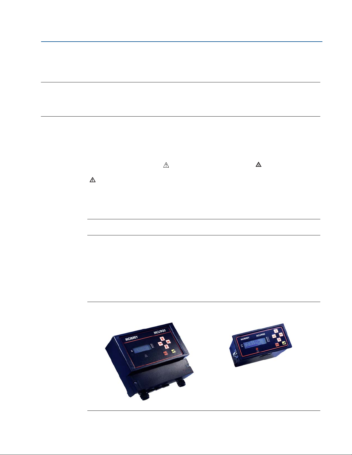
2.2.1 Wall and panel mounting options
The wall mounting option has a tough, weatherproof enclosure for internal or external
installation.
The panel mounting option has a black enclosure, and is designed for control room panel or
cabinet installation.
Figure 2-1. Mounting options
Section 2: Control Unit Overview
3
Page 12
Section 2: Control Unit Overview
B
E
E
20mA
4mA
F
D
D
C
A
G
June 2014
2.2.2 4–20mA HART transmitter input options
4–20mA HART transmitter input options:
The Mobrey MCU901 Standard control unit and the Mobrey MCU90F Logging control
unit accepts one 4–20mA or HART transmitter input
The Mobrey MCU902 Differential control unit accepts two HART transmitter inputs
Note
The Mobrey MCU900 Series is designed for non-hazardous (safe) area installation, but
can be connected to a transmitter installed in a hazardous area.
See Appendix B: Product Certifications for the control unit certifications.
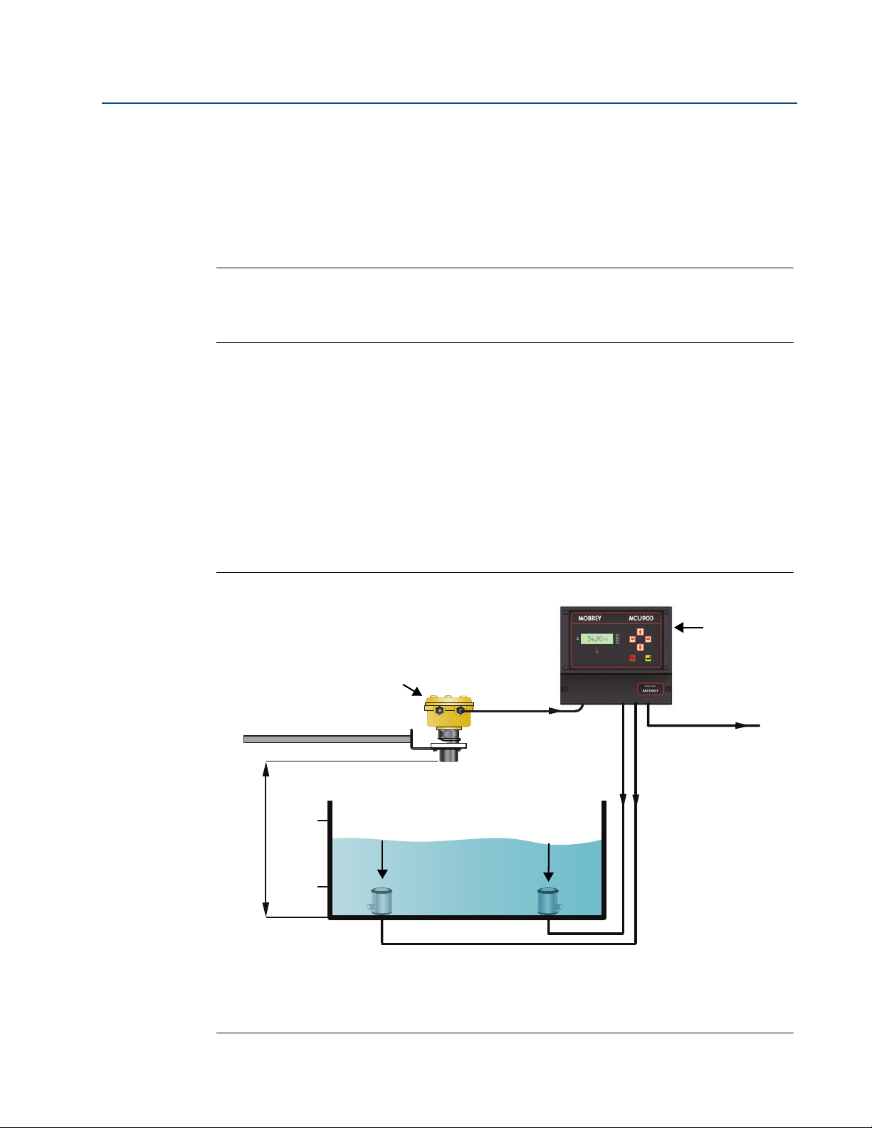
2.2.3 Control functionality
Control functionality is provided by five SPDT voltage-free contact relays in the control unit
(see Figure 2-2 on page 4). The five relay outputs are fully field adjustable to perform a wide
variety of control, fault indication, or alarm duties.
Reference Manual
IP2030/RM, Rev AA
For applications where the control unit functionality is linked to other external events, there are
two digital input ports for accepting contact closure signals.
The isolated 4–20 mA signal output from the Current Output of the control unit is driven by a
Primary / Process Value (PV) e.g. level.
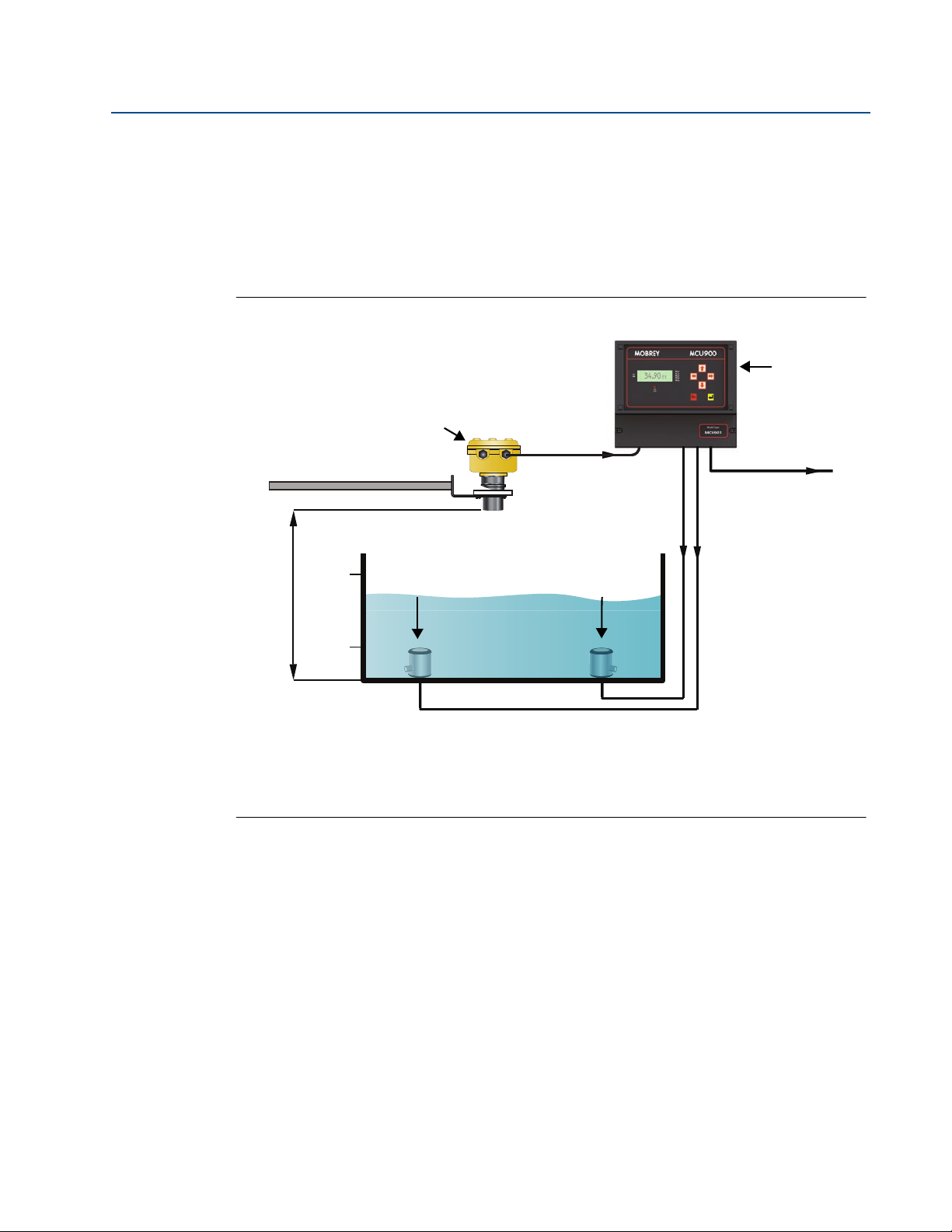
Figure 2-2. Typical application using a Mobrey MCU900 Series control unit
A. Mobrey MSP Series Level Transmitter E. Pump
B. Mobrey MCU900 Series Control Unit F. Transmitter Bottom Reference
C. 4–20 mA signal output G. 4–20 mA and HART signal input
D. Relay
Section 2: Control Unit Overview4
Page 13

Reference Manual
IP2030/RM, Rev AA
2.3 Control unit functions
2.3.1 Standard functions
The Mobrey MCU900 Series control unit provides these standard functions:
Calculation and display of the control unit Primary / Process Value (PV)
The control unit PV is typically a live transmitter reading, which can be any measured
value e.g. level, temperature, or pressure.
Alternatively, the control unit PV is a volume or flow value calculated using the live
transmitter level reading. The control unit is pre-programmed with standard tank
shapes and flow algorithms to simplify the configuration for calculating volume or flow
from the live transmitter level reading. A 20-point programmable look-up table is
provided for non-standard applications.
Output of measured variable as an isolated 4–20mA signal
The output signal is driven by the control unit Primary / Process Value (PV).
Relay control functions
There are five freely assignable relay outputs. By default, Relay 5 is a fault relay but can
be assigned to a control duty. The other relays are available to operate at user-entered
PV values.
Section 2: Control Unit Overview
June 2014
The control unit is pre-programmed with popular pump control routines for wet well
and sump control, along with energy saving overrides.
Voltage-free (digital) contact closure inputs
There are two digital input ports for accepting contact closure signals to override
control unit functions.
HART transmitter interrogation and programming
Any HART transmitter can be connected. The control unit recognizes the transmitter as
an “unknown instrument” but supports the Universal and Common Practice HART
commands (see Appendix E: Support for HART® Transmitters).
When a Mobrey MSP Series HART transmitter is connected, the control unit recognizes
the transmitter and allows full access to the transmitter’s configuration parameters.
Refer to the reference manual of the transmitter for full information about
programming the transmitter parameters (e.g. Transmitter Bottom Reference) using
the MCU900 Series control unit or other HART-based devices.
2.3.2 Difference, sum, and product functions (on MCU902 only)
The Mobrey MCU902 Differential control unit has all the functions of the standard control unit,
plus extra functions for calculating the difference, sum, or product of two separate inputs from
HART transmitters.
2.3.3 Data logging functions (on MCU90F only)
The Mobrey MCU90F Logging control unit has all the functions of the standard control unit, plus
a 7000 event logging function.
Section 2: Control Unit Overview
5
Page 14
Section 2: Control Unit Overview
1.572 m
Esc
12:47
RL1
RL2
RL3
RL4
IN1
IN2
RL5
MCU
A
B
C
June 2014
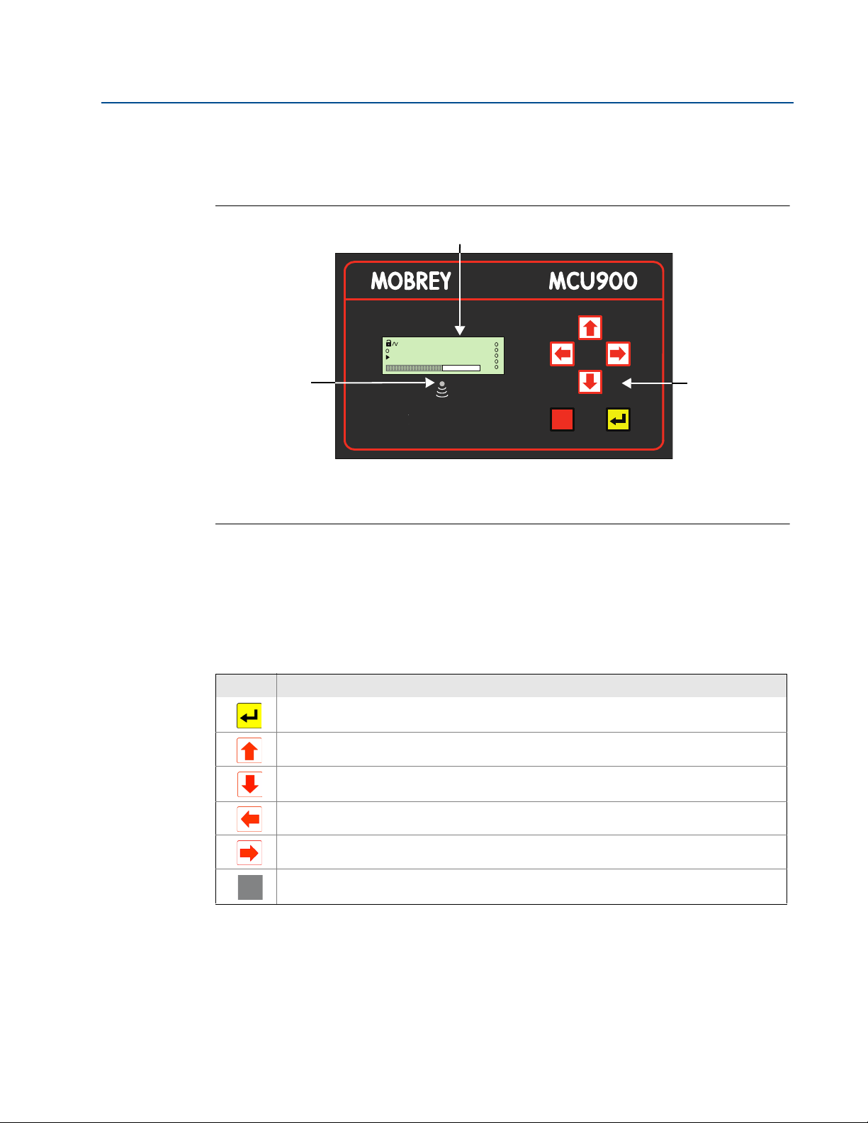
2.4 Control unit front panel
This front panel fascia has an integral keypad, display, and health status LED.
Figure 2-3. Front panel fascia
Reference Manual
IP2030/RM, Rev AA
A. 4-line Back-lit LCD Display
B. Status LED
C. Keypad
2.4.1 Keypad
The membrane keypad has six function buttons (Ta bl e 2 - 1 ). The buttons are used for navigating
a menu system and for viewing or changing application parameters.
Table 2-1. Keypad Function Buttons
Button What the button will do
When the Primary / Process Value (PV) is shown, use the red (ENTER) button to access the menu system.
At other times, this button is for selecting a menu option and for confirming something.
When navigating the menu system, the UP-ARROW button is for moving upwards one line.
At other times, this button is for scrolling through a list of alphanumeric characters or a list of options.
When navigating the menu system, the DOWN-ARROW button is for moving downwards one line.
At other times, this button is for scrolling through a list of alphanumeric characters or a list of options.
The LEFT-ARROW button is for moving left e.g. to another character when editing a parameter value.
The RIGHT-ARROW button is for moving right e.g. to another character when editing a parameter value.
When navigating the menu system, use the ESCAPE button to return to a previous menu level and the
Full PV Display. At other times, e.g. while editing, the button is for restoring a setting that is being edited.
2.4.2 Status LED
The LED is positioned just below the LCD (Figure 2-3 on page 6). It flashes once per second to
indicate that the control unit and transmitters are operating correctly. The LED is constantly lit if
there are operating difficulties e.g. a transmitter fault.
Section 2: Control Unit Overview6
Page 15
Reference Manual
Mobrey MCU901
Mobrey MCU902
B
D
E
A
C
F
G
H
K
I
J
Mobrey MCU90F
IP2030/RM, Rev AA
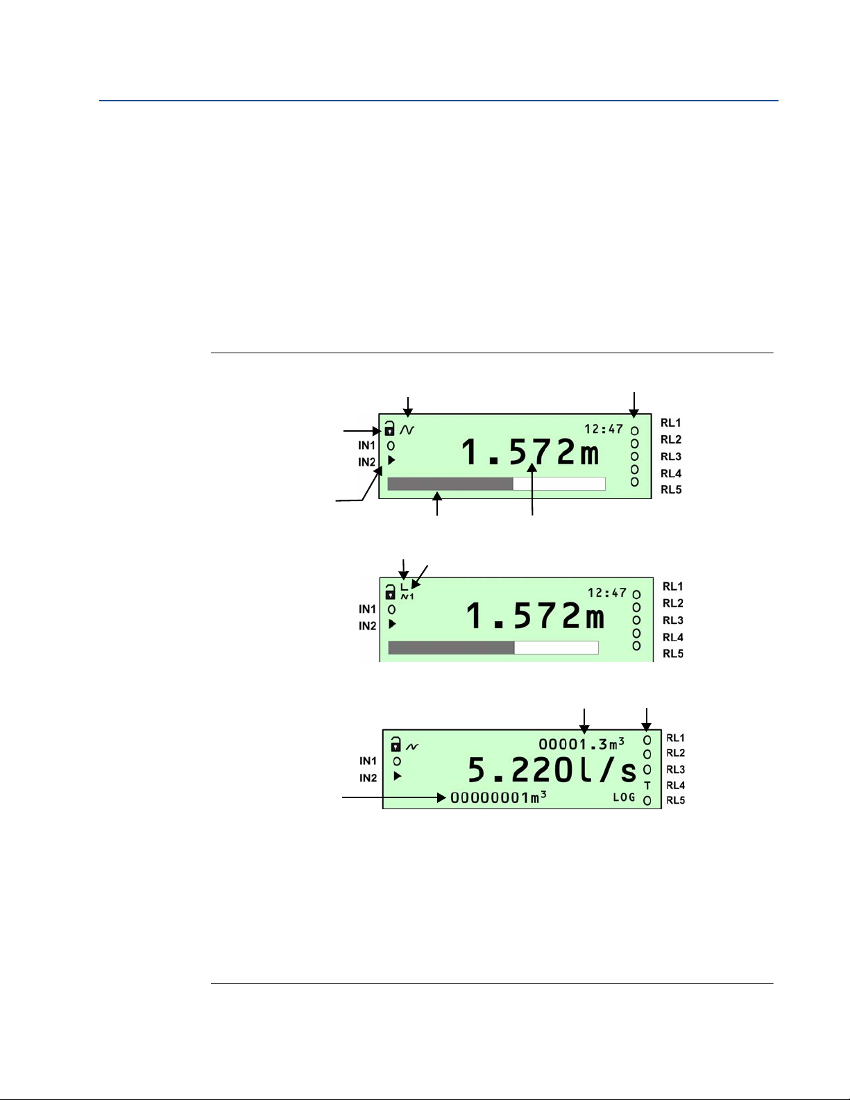
2.4.3 Display
After the power-up and self-checks are completed, the Full PV Display is presented.
The default Full PV Display typically features a digital clock, a measured variable with display
units, and status icons. There are some display differences between control units:
On the MCU901 and MCU902, a bar graph indicates the 4–20mA output signal.
(The MCU90F display can be changed to show the bar graph).
On the MCU902, an extra icon on the first line and indicates if one or two HART
transmitters connected to the control unit.
On the MCU90F, there are two totalizers displayed; one above and one below the
control unit Primary / Process Value (PV).
Figure 2-4. Typical displays of the MCU901, MCU902, and MCU90F
Section 2: Control Unit Overview
June 2014
A. Program/Run App mode (locked padlock = Run App mode) H. HART Transmitter Communicating
B. HART Transmitter Communicating (absent if Idle) (1=Tx1, 2=Tx2)
C. Relay (RL) Status: O = De-energized,
A = Alarm, S = Sampler, T = Totalizer A = Alarm, S = Sampler, T = Totalizer
D. Primary / Process Value (PV) of Control Unit J. Totalizer 1
E. Bar graph of 4–20mA Output K. Totalizer 2 (Daily Total)
F. Digital Input Status: O = Open,
G. HART Transmitter Allocated:
Left Vertical Bar = Tx1; Right Vertical Bar = Tx2
Section 2: Control Unit Overview
= Energized, I. Relay (RL) Status: O = De-energized,= Energized,
= Closed
7
Page 16
Section 2: Control Unit Overview
1.572 m
1.572 m
12:47
1
Full PV Display
Large PV Display
June 2014
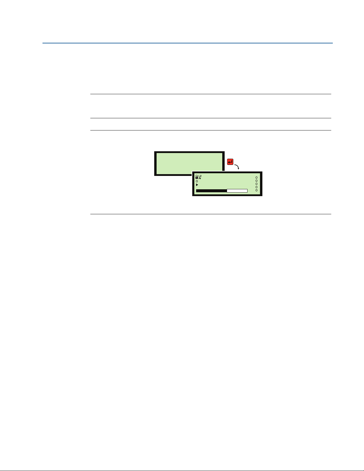
After a period of keypad inactivity, the display automatically changes to the Large PV Display.
This shows only the control unit Primary / Process Value (PV) and Display units, but in a larger
character size to facilitate easier viewing.
To restore the Full PV Display, press the red (ENTER) button.
Note
The Large PV Display feature can be switched off using parameter P574.
See “Display configuration options” on page 102.
Figure 2-5. Large PV Display
Reference Manual
IP2030/RM, Rev AA
Section 2: Control Unit Overview8
Page 17

Reference Manual
IP2030/RM, Rev AA
Section 3 Installation
Safety messages . . . . . . . . . . . . . . . . . . . . . . . . . . . . . . . . . . . . . . . . . . . . . . . . . . . . . . . . . page 9
Considerations before installation . . . . . . . . . . . . . . . . . . . . . . . . . . . . . . . . . . . . . . . . . page 10
Mounting the control unit . . . . . . . . . . . . . . . . . . . . . . . . . . . . . . . . . . . . . . . . . . . . . . . . page 11
Electrical installation . . . . . . . . . . . . . . . . . . . . . . . . . . . . . . . . . . . . . . . . . . . . . . . . . . . . . page 13
3.1 Safety messages
Procedures and instructions in this manual may require special precautions to ensure the safety
of the personnel performing the operations. Information that raises potential safety issues is
indicated by a caution symbol ( ). The external hot surface symbol ( ) is used when a surface
is hot and care must be taken to avoid possible burns. If there is a risk of an electrical shock the
( ) symbol is used. Refer to the safety messages listed at the beginning of each section before
performing an operation preceded by this symbol.
Section 3: Installation
June 2014
Failure to follow these installation guidelines could result in death or serious injury:
The Mobrey MCU900 Series control unit must be installed, connected,
commissioned, operated, and maintained by suitably qualified personnel only,
observing any national and local requirements that may apply
Use the equipment only as specified in this manual. Failure to do so may impair the
protection provided by the equipment
Explosions could result in death or serious injury:
Please review the approvals section of this reference manual for any restrictions
associated with an installation
Electrical shock could cause death or serious injury:
If the control unit is installed in a high voltage environment and a fault condition or
installation error occurs, high voltage may be present on leads and terminals
Use extreme caution when making contact with the leads and terminals
Make sure that power to the control unit is off while making connections
Section 3: Installation
9
Page 18

Section 3: Installation
June 2014
3.2 Considerations before installation
Note
The Mobrey MCU900 Series is designed for non-hazardous (safe) area installation, but can
power and take input from an intrinsically safe transmitter installed in a hazardous area.
See Appendix B: Product Certifications for the control unit certifications.
3.2.1 Safety considerations
Guidelines
1. This product is classified type A in accordance with European EMC directive
2004/108/EC. To ensure electro-magnetic compatibility, in any member country, this
product should not be installed in a residential area.
2. Do not mount the control unit on a structure that is subject to vibration, or in a position
where damage may be caused by impact, thermal stress or liquid ingress.
3. The fuse must only be replaced with the type specified (see page 108 for procedure).
Reference Manual
IP2030/RM, Rev AA
4. If the equipment is likely to come into contact with aggressive substances, it is the
responsibility of the user to take suitable precautions that prevent it from being
adversely affected, thus ensuring that the type of protection is not compromised.
Aggressive Substances - e.g. acidic liquids or gases that may attack metals or solvents
that may affect polymeric materials.
Suitable Precautions - e.g. regular checks as part of routine inspections or establishing
from the material's data sheet that it is resistant to specific chemicals.
5. The user should not repair this equipment.
6. Terminal 30 (intrinsically safe earth/ground) of the control unit must be connected to a
high integrity earth/ground point.
7. A mains powered Control Unit must not be connected to a supply exceeding 250 V
r.m.s. or dc, or to apparatus containing a source of voltage exceeding 250 V r.m.s. or dc.
8. A direct current (dc) powered control unit must not be connected to a supply
exceeding 30 Vdc or apparatus containing a source of voltage exceeding 30 Vdc.
9. The intrinsically safe outputs of the control unit may be connected to certified
equipment used in a hazardous area. Refer to Appendix B: Product Certifications for
details of relevant certifications.
10. Cable between the MCU900 Series control unit and a transmitter should be shielded,
twisted-pair with the shield connected to terminal 3 (marked with earth symbol) on the
MCU900 Series control unit. The shield should be left unconnected at the transmitter
unless there is a terminal specifically provided for this purpose.
11. Cable runs should be separate from any high voltage or mains cables to avoid crosstalk
or interference.
12. Refer to the technical data in Appendix A: Reference Data.
Section 3: Installation10
Page 19

Reference Manual
IP2030/RM, Rev AA
3.3 Mounting the control unit
3.3.1 Mounting the wall-mount version
Guidelines
This housing is rated IP65. It is suitable for mounting outside, but this should be above
any flood level, away from any overflow path, and away from direct sunlight
Do not mount the control unit on a structure that is subject to vibration, or in a position
where damage may be caused by impact, thermal stress, or liquid ingress
The mass of the mains powered unit is 1.4 kg, and the DC powered unit is 1.0 kg.
To conform with safety requirements, the wall on which the unit is mounted should be
capable of supporting four times this weight
It is not necessary, or advisable, to remove the upper part of the unit housing that
contains the LCD and keypad. There are no user serviceable parts inside. The unit must
not be modified in any way
Procedure
Section 3: Installation
June 2014
1. Mount the unit on a suitable wall or structure using the fixing points shown on
Figure A-1 on page 121.
2. Make the electrical connections
(see “Making electrical connections on wall-mount units” on page 13).
3.3.2 Mounting the panel version
Guidelines
This housing is rated IP40 and is designed for panel mounting in a weatherproof
environment. An optional fascia overlay hood is available which improves the IP rating
to IP65 – see Product Data Sheet IP2031 on the Mobrey brand pages at
www.emersonprocess.com for ordering information
Do not mount the control unit on a structure that is subject to vibration, or in a position
where damage may be caused by impact, thermal stress, or liquid ingress
Where three of more units are fitted in the same cabinet or panel, ensure that there is
adequate air circulation to aid cooling. It is recommended that an air circulation fan be
fitted
The unit requires at least 6.5 in. (165 mm) clearance behind the mounting panel to
avoid cable fouling
After mounting the control unit, all wiring is made at the rear of the unit using the two
part terminal blocks provided. (A pre-wired data download socket suitable for front
panel mounting is provided on the MCU90F)
Section 3: Installation
Mount the control unit on a panel with thickness 1.5 to 10 mm, ensuring the panel is
strong enough to support the 2.6 lb. (1.2 kg) weight of the unit
Ensuring there is enough clearance behind the chosen position in the panel (6.5 in [165
mm] minimum), cut a horizontal slot 5.43 in. (138 mm) long by 2.68 in. (68 mm) high
in the panel and remove any rough edges
11
Page 20

Section 3: Installation
C
B
A
June 2014
Procedure
1. Unpack the two screw clips provided.
2. Identify the moulded lugs (protrusions) in the recesses on each side of the control unit.
3. Holding the screwdriver-slot-end of the threaded spindle of one of the screw clamps
4. Remove the screw clamps from both of the screw clamp frames.
5. Slide the control unit into the panel, ensuring that the panel seal provided is in place
6. Re-fit the screw clamps, one on each side, and tighten with a screwdriver to clamp the
Reference Manual
IP2030/RM, Rev AA
(Ignore the recesses on the top and bottom of the unit).
and looking at the control unit rear, engage a screw clamp frame onto the control unit
side (see Figure 3-1 on page 12) and see how the four steel lugs (protrusions) of the
screw clamp frame engage with the moulded lugs of the unit. Gently pull the screw
clamp for the lugs to engage with each other.
behind the front panel bezel.
control unit against the panel.
7. For electrical connections,
see “Making electrical connections on panel-mount units” on page 15.
Figure 3-1. The fitted screw clamp
A. Screw Clamp Frame
B. Front Panel Bezel
C. Screw Clamp With Threaded Spindle
Section 3: Installation12
Page 21

Reference Manual
IP2030/RM, Rev AA
3.4 Electrical installation
It is the responsibility of the installer to:
Refer to safety data and electrical specifications in Appendix A: Reference Data
Refer to the certifications and control drawings in Appendix B: Product Certifications
Check and obtain any work permits required before applying power to the unit
Observe all local regulations and approval requirements
Ensure the wiring is suitable for the load current
Ensure the wiring insulation is suitable for the voltage, temperature, and environment
of the installation
Ensure suitable cable glands or conduit connections are used when wiring to the
control unit to maintain enclosure integrity
Never remove or modify the mechanical barriers separating the terminal area from the
main enclosure and separating the transmitter input terminals from other terminals.
Section 3: Installation
June 2014
3.4.1 Making electrical connections on wall-mount units
All field wiring connections are accessible by removing the lower terminal cover, which is
secured by two screws on the wall-mount control unit.
The cabling between the Mobrey MCU900 Series control unit and a transmitter should be a
screened (shielded), twisted-pair type with the cable screen (shield) connected to terminal 3
(marked with earth/ground symbol) on the Mobrey MCU900 Series control unit. The cable
screen (shield) should be left unconnected at the transmitter end unless there is a terminal
specifically provided for this purpose.
Cable runs should be separate from any high voltage or mains cables to avoid crosstalk or
interference.
Figure 3.4.2 on page 15 shows the layout of the control unit terminals. All terminal blocks are
suitable for wires 14 to 26 AWG (0,5 to 1,5 mm
for wires 10 AWG (2,5 mm
). Insulation should be stripped back 1/4 in. (7 mm).
Transmitter connections are made on the left side of the terminals enclosure. The intrinsically
safe earth/ground (terminal 30) must be connected to a high integrity earth/ground point if the
transmitter connected to terminals 1 and 2 is sited in a hazardous area.
Note
Use only 167 F (75 C) copper conductors for field wiring.
), except the mains terminals which are suitable
Section 3: Installation
Note
In intrinsically safe systems, apparatus connected to the MCU900 Series control unit
must not be supplied from a voltage greater than 250V r.m.s. or 250 Vdc.
13
Page 22
Section 3: Installation
10 11 12
0VIN2IN1
789
24V
I
out
0V
456
RX TX
0V
1316141715
18
NO COM NC
NCCOMNO
25 26 27
NO
COM
NC
1922202321
24
NO COM NC
NCCOMNO
1
24V
I
in
2 3
FUSE
200mA (T)
28
L
N
29 30
IS EARTH
June 2014
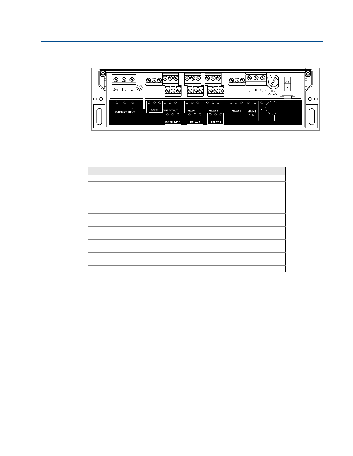
Figure 3-2. Connection terminals layout (for mains-powered wall-mount unit)
(The direct current (dc) powered unit has a slightly different layout – terminals 31 and 32 replace terminals 28 and 29).
Table 3-1. Connection terminal descriptions (for wall-mount unit)
Ter mi na l Function Terminal marking
1 Loop supply 24V
2 Current input Iin
3 Cable screen Earth (Earth symbol)
4-6 RS232 RX-TX-0V
7-9 Current output 24V-Iout-0V
10-12 Digital input 1 and 2 IN1-IN2-0V
13-15 Relay 1 NO-COM-NC
16-18 Relay 2 NO-COM-NC
19-21 Relay 3 NO-COM-NC
22-24 Relay 4 NO-COM-NC
25-27 Relay 5 NO-COM-NC
28-29
30 I.S. Earth/Ground (Earth/Ground symbol)
31
32
(1) Mains-powered control unit only.
(2) Direct current (dc) powered control unit only.
Reference Manual
IP2030/RM, Rev AA
(1)
(2)
(2)
Mains input L-N
Negative Positive +
Cable glands for the wall-mount unit
The five cable-entry positions are pre-drilled to accept M20 cable glands. The Mobrey MCU90F
control unit has a data download socket factory pre-fitted in one of these cable-entry positions.
Two cable glands, rated IP65 and suitable for cable with outside diameter 4 to 7 mm, are
supplied for use with the mains supply and transmitter cable. M20 blanking plugs are supplied
for the other three cable entry positions.
All glands and blanking plugs are supplied in a plastic bag. The installer must fit these, or
suitable equivalents, in place of the transit red-caps, to ensure weatherproofing of the control
unit. The white sealing washers supplied with the cable glands and blanking plugs must be fitted
on the outside of the enclosure under gland/blanking plug.
Section 3: Installation14
Page 23
Reference Manual
IP2030/RM, Rev AA
Section 3: Installation
3.4.2 Making electrical connections on panel-mount units
Field wiring connections are made to the back of the panel-mount control unit using the
two-part (plug/socket) terminal connectors provided. Figure 3-3 shows the rear panel layout.
Note
The plug/socket terminal connectors on the panel mount unit are polarized (keyed)
to prevent inter-changeability and incorrect connection.
Cabling between the Mobrey MCU900 Series control unit and a transmitter should be a
screened (shielded), twisted-pair type with the cable screen (shield) connected to terminal 3
(marked with earth/ground symbol) on the control unit. The cable screen (shield) should be left
unconnected at the transmitter end unless there is a terminal specifically provided for this
purpose. Cable runs should be separate from any high voltage or mains cables to avoid crosstalk
or interference.
Connect terminal 30 (intrinsically safe earth/ground) to a high integrity earth/ground point if
the transmitter connected to terminals 1 and 2 is sited in a hazardous area.
June 2014
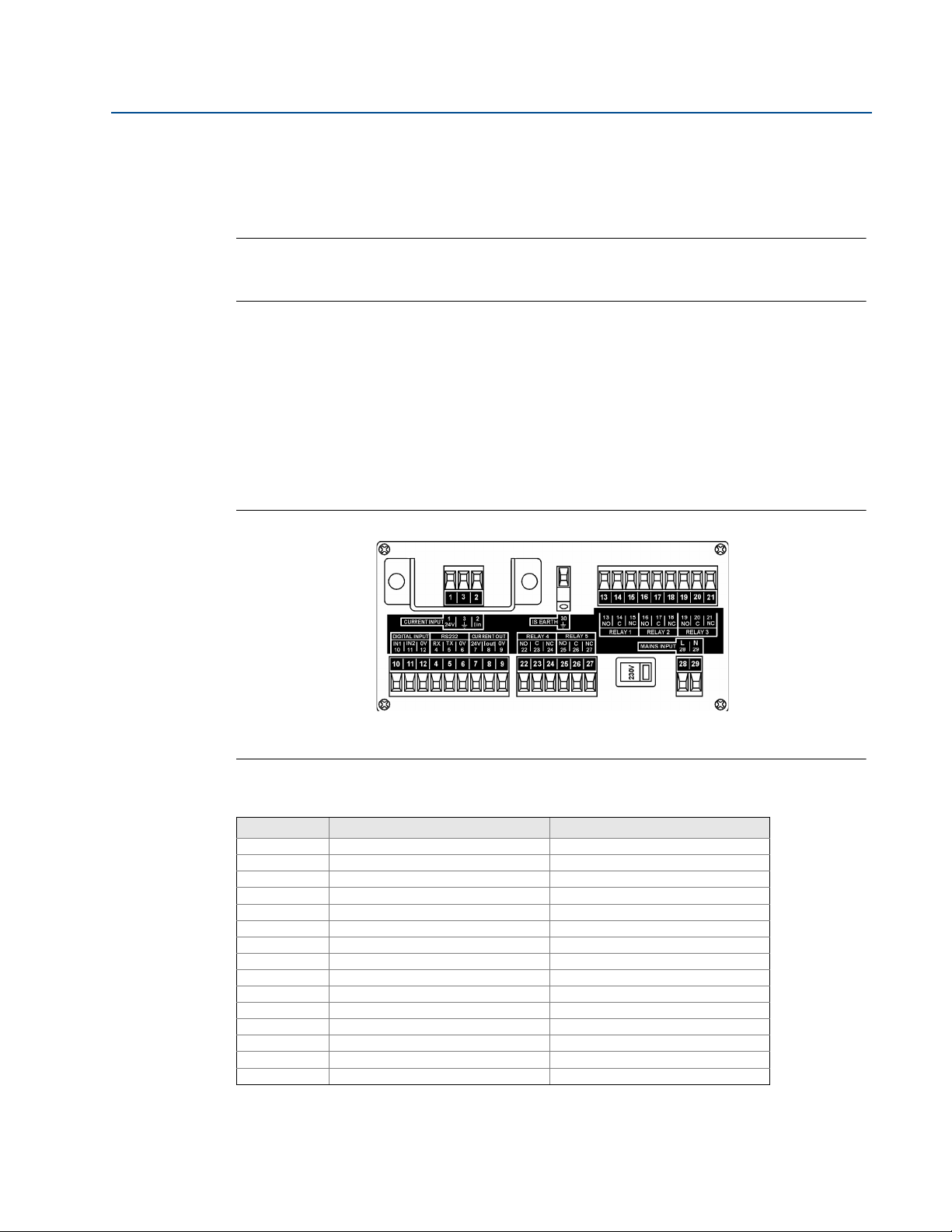
Figure 3-3. Connection terminals layout (for mains-powered panel-mount unit)
(The direct current (dc) powered unit has a slightly different layout – terminals 31 and 32 replace terminals 28 and 29).
Table 3-2. Connection descriptions for panel mount unit
Ter mi na l Function Terminal marking
1 Loop supply 24V
2 Current input Iin
3 Cable screen Earth (Earth symbol)
4-6 RS232 RX-TX-0V
7-9 Current output 24V-Iout-0V
10-12 Digital input 1 and 2 IN1-IN2-0V
13-15 Relay 1 NO-COM-NC
16-18 Relay 2 NO-COM-NC
19-21 Relay 3 NO-COM-NC
22-24 Relay 4 NO-COM-NC
25-27 Relay 5 NO-COM-NC
(1)
28-29
30 I.S. Earth (Earth symbol)
(2)
31
(2)
32
(1) Mains-powered control unit only.
(2) Direct current (dc) powered control unit only.
Mains input L-N
Negative Positive +
Section 3: Installation
15
Page 24

Section 3: Installation
June 2014
3.4.3 Power connections
When the control unit is powered by mains alternating current (ac) power, select the voltage as
115V or 230V using the voltage-selector slide switch.
When the control unit is direct current (dc) powered, ensure the supply is adequate (15 to 30
Vdc). Do not exceed 30 Vdc.
A switch or circuit breaker should be installed in close proximity to the instrument, and labelled
as such. Although the Mobrey MCU900 Series control unit meets all European standards for
surge immunity on power and signal lines, it is recommended that lightning suppressors are
also fitted if local conditions make this advisable.
3.4.4 Earthing connections
The IP-rated Mobrey MCU900 Series control unit is double insulated and does not require a
mains earth.
Do not connect terminal 30 to a mains earth. Terminal 30 is provided for use as an intrinsically
safe (or functional) earth connection, which must be used when a transmitter is mounted in a
hazardous area and is connected to terminals 1 and 2.
Reference Manual
IP2030/RM, Rev AA
Terminal 3 is to be used for connection of a twisted-pair cable screen (shield) when the control
unit is powering the transmitter (see Figure 3-4 on page 17). This screen (shield) should be left
unconnected at the transmitter end unless there is a terminal provided for this purpose.
When connected to equipment located in a hazardous area, not meeting the requirements of
clause 6.3.12 (Isolation of circuits from earth or frame) in IEC 60079-11:2006
(EN 60079-11:2007), equipotential earthing must be ensured between the equipment and the
intrinsically safe earth. An example of equipotential earthing is a cable with a cross-sectional
2
area greater than 4 mm
and a resistance of less than 1 ohm.
3.4.5 Transmitter connections and cabling
Connection of a transmitter to the control unit does not confer intrinsic safety on the
transmitter. It is the responsibility of the user to ensure any transmitter installed in a hazardous
area is suitable for use and certified accordingly. The installation should be in accordance with a
recognized code of practice.
Check that the electrical parameters of the installed system of control unit, transmitter, any
loop-powered devices, and interconnecting cable to ensure compliance with the product
certificates and technical data. Particular attention must be given to the cable and the
transmitter to ensure that the total capacitance and inductance limits stated in the technical
data in Appendix B: Product Certifications are not exceeded.
Cable joins are allowable in cabling the transmitter, provided that the joint is made within an
IP20/NEMA 3 (minimum) enclosure suitable for the environment, and that wiring withstands a
test voltage of 500 V r.m.s. to earth.
The maximum length of cable permissible between the transmitter and control unit is
determined by limits imposed by the intrinsic safety certificates of the instruments and control
drawings.
Section 3: Installation16
Page 25
Reference Manual
A
B
24 V
I
IN
1
2
3
1
2
3
A
B
24 V
I
IN
IP2030/RM, Rev AA
Section 3: Installation
June 2014
No other outputs from the control unit must be routed through a hazardous area unless
protected by an additional I.S. Barrier (not supplied).
It is the responsibility of the user to ensure that any transmitter is installed in accordance with
the manufacturer’s instructions supplied with the transmitter.
Cable between the MCU900 Series control unit and a transmitter should be shielded
twisted-pair with the shield connected to terminal 3 (marked with earth symbol) on the
MCU900 Series control unit. The shield should be left unconnected at the transmitter unless
there is a terminal specifically provided for this purpose.
Cable runs should be separate from any high voltage or mains cables to avoid crosstalk or
interference. Multi-core cable may be used if the other cores carry only low voltage (24 Vdc
nominal) signals and each pair of cores is individually screened (shielded).
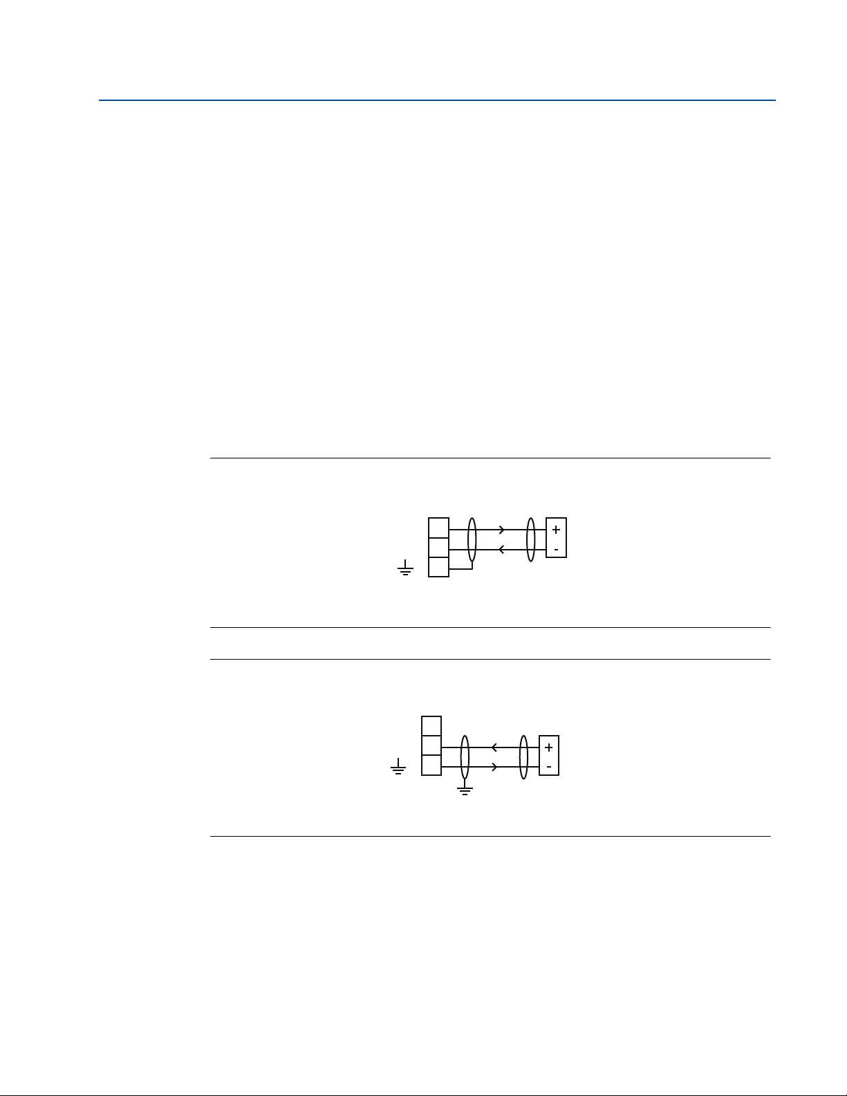
Loop-powered transmitters must be connected to terminals 1, 2, and 3 on the control unit
(see Figure 3-4).
The MCU900 Series control unit supplies 23 Vdc from a 400 Ohm source to power transmitters.
Separately powered transmitters must be connected to terminals 2 and 3 (see Figure 3-5).
Figure 3-4. Loop-powered transmitter connections to MCU900 Series control unit
1
2
3
A. Control unit
B. Transmitter
Figure 3-5. Self-powered transmitter connections to MCU900 Series control unit
A. Control unit
B. Transmitter
Section 3: Installation
17
Page 26
Section 3: Installation
1
2
3
1
2
3
A
A
BB
C
June 2014
Reference Manual
IP2030/RM, Rev AA
3.4.6 Connecting HART transmitters to the Mobrey MCU902
The Mobrey MCU902 control unit takes the input from two HART transmitters and calculates
the sum, difference, or product of the two inputs.
Note
The transmitters must be HART compatible for the MCU902 to operate correctly.
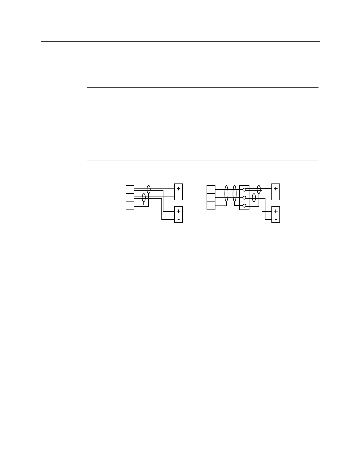
Connection of the two transmitters to the MCU902 can be done by:
cabling both transmitter cables wired directly into Current Input terminals on the
MCU902 (Figure 3-6), or
using a single cable wired directly into Current Input terminals with the two
transmitters connected to this single cable via a suitable junction box (Figure 3-6).
Figure 3-6. Connecting two HART transmitters to the Mobrey MCU902
A. HART Transmitter Tx1
B. HART Transmitter Tx2
C. Junction box
For correct operation, each HART transmitter must be changed to “multi-drop” mode to allow
them to communicate with the Mobrey MCU902 control unit through a common connection.
Each HART transmitter must therefore have their poll address changed from the factory default
address of “0” to a unique address.
The MCU902 control unit is used to achieve this address change, but requires the transmitters
to be connected in a specific sequence as detailed here:
1. With the power supply turned off, connect the first HART transmitter to the Current
Input terminals on the MCU902 control unit (see Figure 3-6).
2. Check the voltage-selector-switch is set for the correct voltage on the
mains-powered control unit (115 or 230 Vac), and then turn the power on.
3. After applying power, the control unit searches for a HART transmitter.
A HART transmitter with the factory default polling address of 0 is found after 15
seconds. The control unit automatically changes the Transmitter Poll Address from “0”
to “1” and it is designated “Tx1” (Transmitter 1) and assigned to Channel 1.
The control unit reads parameters from the HART transmitter and makes them
available for local interrogation and programming within the menu system.
Section 3: Installation18
Page 27

Reference Manual
IP2030/RM, Rev AA
Section 3: Installation
June 2014
4. When an un-configured Mobrey MSP Series Level Transmitter is being used for the first
time, a prompt appears asking for the Trans mitter [1] B ottom Refe r ence.
If commissioning the system now, edit and save a new Transmitter Bottom Reference or
keep the existing Transmitter Bottom Reference. After the start-up process is complete,
the display appears showing a measurement e.g. liquid level or the menu system.
If the system is not to be commissioned at this time, simply switch off the power and
the same prompt re-appears when switching on the power next time. The Transmitter
Bottom Reference can be changed later, but it is better to get it correct now.
Note
If the Re-connecting to Digital Transmitter message does not appear, check that the
operating mode of the control unit is set to Run App mode (see page 38) and that the
Input Channel Source is set for a digital HART input (see page 48 or page 50)
5. Turn the power supply off and connect the second HART transmitter (see Figure 3-6),
such that both HART transmitters are connected at the same time.
6. Turn the power supply on.
7. The MCU902 control unit searches for, and detects, the two connected HART
transmitters.
After the second HART transmitter is found, the control unit automatically changes the
Transmitter Poll Address from “0” to “2” and it is designated “Tx2” (Transmitter 2) and
assigned to Channel 2.
The control unit reads parameters from the HART transmitter and makes them
available for local interrogation and programming within the menu system.
8. When an un-configured Mobrey MSP Series Level Transmitter is being used for the first
time, a prompt appears asking for the Trans mitter [2] B ottom Refe r ence.
If commissioning the system now, edit and save a new Transmitter Bottom Reference or
keep the existing Transmitter Bottom Reference. After the start-up process is complete,
the display appears showing a measurement e.g. liquid level or the menu system.
If the system is not to be commissioned at this time, simply switch off the power and
the same prompt re-appears when switching on the power next time. The Transmitter
Bottom Reference can be changed later, but it is better to get it correct now.
9. The two HART transmitters are now known to the control unit, and will be remembered
each time the power is switched off and on.
Section 3: Installation
19
Page 28
Section 3: Installation
Internally Powered Loop Powered
June 2014
3.4.7 Relay connections
The five voltage-free contact relays are grouped as shown in Tab l e 3 -3 . Whilst each relay is
individually double-insulated, their arrangement is such that the insulation between relays in
the same group is standard or ‘basic’ insulation. Care must be taken in order to avoid the risk
of electric shock. It is allowed to use relays in the same group to control circuits with both mains
and dc, or low voltage circuits.
Note
The relay labels (NO-C-NC) in Ta b l e 3- 1 and Ta bl e 3 - 2 represent the relay terminals in
the de-energized state.
Table 3-3. Relay configuration groups
Wall Mount MCU900 Series control unit Panel Mount MCU900 Series control unit
Relay 1 and 2: Group 1 Relay 1, 2 and 3 : Group 1
Relay 3 and 4 : Group 2 Relay 4 and 5 : Group 2
Relay 5: Group 3
Reference Manual
IP2030/RM, Rev AA
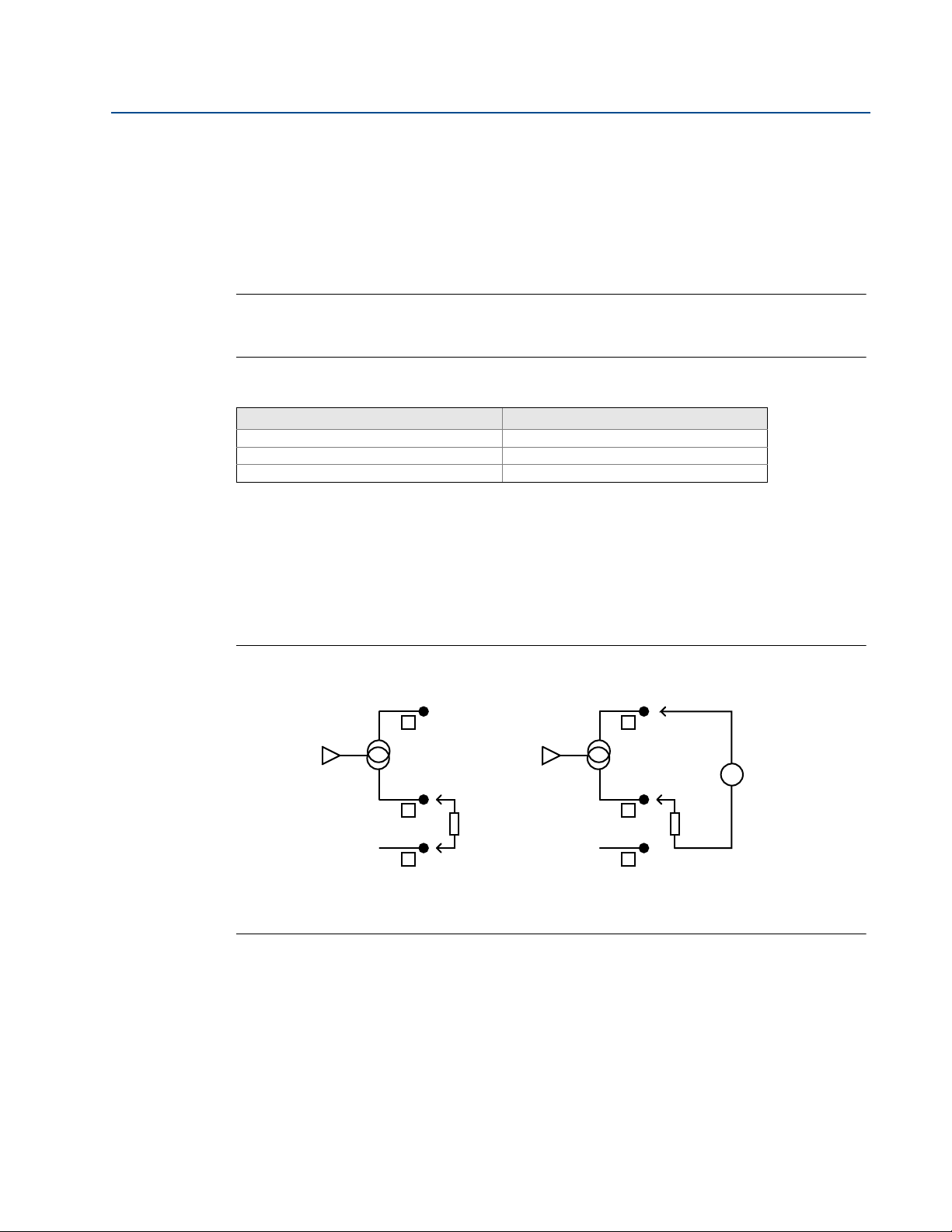
3.4.8 Current output connections
The Current Output may be connected in internally-powered or loop-powered mode, as shown in
Figure 3-7. In loop-powered mode, an external power source is required. A minimum of 2.5 V dc
is required across terminals 7 and 8 for correct operation. The voltage must not exceed 30 Vdc.
Figure 3-7. Alternative output current configurations
24V
7
Io
8
0V
9
+
Load
-
24V
0V
7
+
External
Supply
Io
8
+
Load
-
-
9
Section 3: Installation20
Page 29

Reference Manual
IP2030/RM, Rev AA
3.4.9 Digital control voltage-free contact inputs
There are two trigger inputs, IN1 and IN2. Each input is connected as shown in Figure 3-8.
Figure 3-8. Connections for external trigger input
Section 3: Installation
June 2014
External
Contact
Closure
IN
or10 11
0V
12
Section 3: Installation
21
Page 30
Section 3: Installation
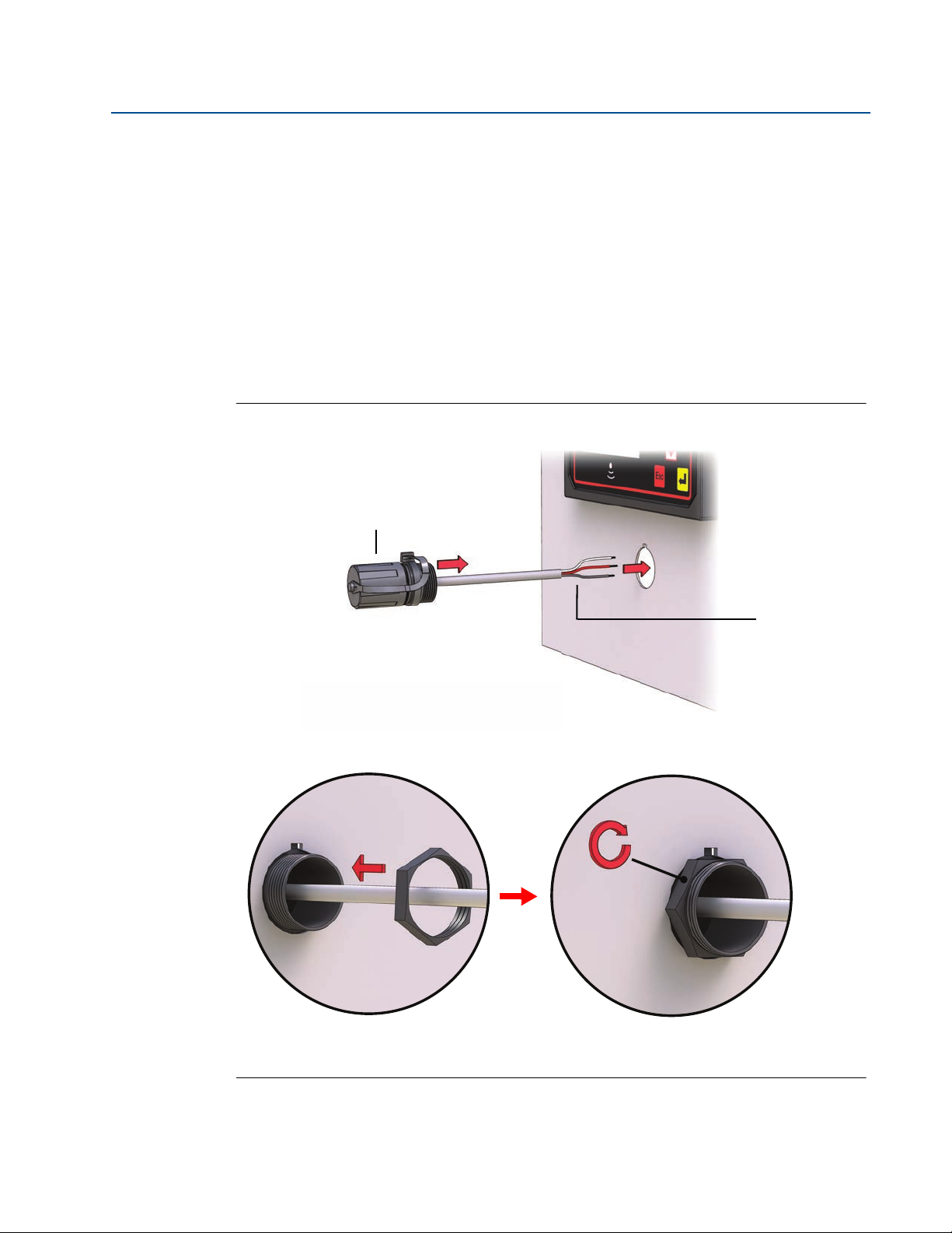
Note B
Use the supplied mini-B nut to secure the socket to the panel.
Note A
Cut-out the hole in the panel to the dimensions
shown in Figure A-2 on page 122.
June 2014
3.4.10 RS232 connections
The RS232 connections, terminals 4, 5 and 6, are for downloading logged data to a PC or a
handheld device.
Wall-mountable Mobrey MCU90F control units are supplied with a factory pre-fitted
RS232 data-download socket, which is also pre-wired to terminals 4, 5, and 6.
The panel-mountable Mobrey MCU90F control unit is supplied with a data-download
socket ready to be fitted to a panel (see Figure 3-9 on page 22) and then wired to
terminals 4, 5, and 6 on the rear of the control unit (see Figure 3-10 on page 23).
When there is data to be downloaded using Mobrey LOG-VIEW or other software, connect the
RS232 data-download cable supplied with the socket (see Figure 3-11 on page 23).
Figure 3-9. Fitting the RS232 data-download socket to a panel
Reference Manual
IP2030/RM, Rev AA
A. RS232 socket with cap fitted.
B. RS232 socket flying lead.
Section 3: Installation22
Page 31

Reference Manual
4: Rx (White)
5: Tx (Red)
6: 0V (Black)
Note B
Note A
Note C
IP2030/RM, Rev AA
Section 3: Installation
June 2014
Figure 3-10. Wiring the socket flying lead to terminals 4, 5, and 6 (panel mount unit)
Figure 3-11. Connecting the RS232 data-download cable supplied with the socket
A. RS232 data-download cable.
B. Unscrewed socket cap.
C. See Mobrey LOG-VIEW manual IP130 for further information on downloading logged data.
Section 3: Installation
23
Page 32

Section 3: Installation
June 2014
Reference Manual
IP2030/RM, Rev AA
Section 3: Installation24
Page 33

Reference Manual
IP2030/RM, Rev AA
Section 4 Getting started
Safety messages . . . . . . . . . . . . . . . . . . . . . . . . . . . . . . . . . . . . . . . . . . . . . . . . . . . . . . . . .page 25
Switching on the MCU901 and MCU90F for the first time . . . . . . . . . . . . . . . . . . . . page 26
Switching on the MCU902 for the first time . . . . . . . . . . . . . . . . . . . . . . . . . . . . . . . . page 29
A quick tour of the menu system . . . . . . . . . . . . . . . . . . . . . . . . . . . . . . . . . . . . . . . . . . page 30
Programming the control unit . . . . . . . . . . . . . . . . . . . . . . . . . . . . . . . . . . . . . . . . . . . . page 32
4.1 Safety messages
Procedures and instructions in this section may require special precautions to ensure the safety
of the personnel performing the operations. Information that raises potential safety issues is
indicated by a warning symbol ( ). Refer to the safety messages listed at the beginning of each
section before performing an operation preceded by this symbol.
Section 4: Getting started
June 2014
Failure to follow these installation guidelines could result in death or serious injury:
The Mobrey MCU900 Series control unit must be installed, connected,
commissioned, operated, and maintained by suitably qualified personnel only,
observing any national and local requirements that may apply
Use the equipment only as specified in this manual. Failure to do so may impair the
protection provided by the equipment
Explosions could result in death or serious injury:
Please review the approvals section of this reference manual for any restrictions
associated with an installation
Electrical shock could cause death or serious injury:
If the control unit is installed in a high voltage environment and a fault condition or
installation error occurs, high voltage may be present on leads and terminals
Use extreme caution when making contact with the leads and terminals
Make sure that power to the control unit is off while making connections
Section 4: Getting started
25
Page 34
Section 4: Getting started
B
E
E
20mA
4mA
F
D
D
C
A
G
June 2014
Reference Manual
IP2030/RM, Rev AA
4.2 Switching on the MCU901 and MCU90F for the
first time
The Mobrey MCU901 and MCU90F control units accept the input from a single HART or
4–20 mA transmitter. Connect the transmitter to the Current Input terminals on the control
unit as explained in the section “Electrical installation” on page 13.
Figure 4-1. The Mobrey MCU901 or MCU90F control unit with one transmitter
A. Mobrey MSP Series Transmitter E. Pump
B. Mobrey MCU900 Series Control Unit F. Transmitter Bottom Reference
C. 4–20 mA signal output G. 4–20 mA and HART signal input
D. Relay
Section 4: Getting started26
Page 35

Reference Manual
Re-connecting to
Digital Transmitter
Please Wait
Re-connecting to
Digital Transmitter
Please Wait
Re-connecting to
Digital Transmitter
Please Wait
(start of search)
(after 3 seconds)
(after 15 seconds)
IP2030/RM, Rev AA
Section 4: Getting started
June 2014
4.2.1 Switching on with one new HART transmitter connected
After applying power, the control unit first displays the control unit version e.g. MCU901 and the
software version. It then automatically searches for a HART transmitter.
Figure 4-2. Searching for a HART transmitter after applying power
A HART transmitter with the factory default polling address of 0 is found after 15 seconds.
When found by the controller, it is designated “Tx1” (Transmitter 1) and assigned to Channel 1.
However, if the polling address is in the range 1 to 15, a prompt appears allowing the polling
address and the tag name to be changed. This is optional, and pressing the red (ENTER) button
continues the start-up process.
At this time, the control unit reads parameters from the HART transmitter and makes them
available for local interrogation and programming within the menu system of the control unit.
When an un-configured Mobrey MSP Series Level Transmitter is being used for the first time, a
prompt appears asking for the Transmitter Bottom Referen ce (Figure 4-3). This value is used
to automatically set-up the 4–20 mA output span of the transmitter over this range.
If the system is not to be commissioned at this time, simply switch off the power and the same
prompt re-appears when switching on the power next time. The Transmitter Bottom Reference
can be changed later, but it is better to get it correct now.
If commissioning the system now, edit and save a new Transmitter Bottom Reference or
keep (save) the existing Transmitter Bottom Reference (Figure 4-3).
Note
If the Re-connecting to Digital Transmitter message does not appear, check that the
operating mode of the control unit is set to Run App mode (see page 38) and that the
Input Channel Source is set for a digital HART input (see page 48 or page 50)
After the start-up process is complete, the display appears showing a measurement e.g. liquid
level or the menu system. The value on the display is the Primary / Process Variable (PV) of the
control unit, but this can be changed (see “Display configuration options” on page 102).
Section 4: Getting started
Whenever power is lost and restored, the control unit re-establishes digital communications
with the HART transmitter and the PV display re-appears.
27
Page 36
Section 4: Getting started
Re-connecting to
Digital Transmitter
Please Wait
Bottom Reference =
distance to sensor
from tank bottom
=Continue
Edit Transmitter
Bottom Reference ?
12.000 m
ESC=No =Yes
to edit
Bottom Reference
06.500 m
ESC=Back =Save
5
Save new
Bottom Reference ?
06.500 m
ESC=No =Yes
Bottom Reference
saved.
Setup controller ?
ESC=No =Yes
Esc
Esc
Esc
Esc
Save
Bottom Reference ?
12.000 m
ESC=No =Yes
Esc
x4
Controller SETUP
menu appears –
Use App Wizard
(see page 39)
Controller MAIN
menu appears
(Yes)
(Yes)
(Yes)
(No)
(No)
(Back)
(No)
(Continue)
(06.500 m)
(No)
(Yes)
Note A
Note B
x5
x2
June 2014
Figure 4-3. Prompts for Transmitter Bottom Reference
Reference Manual
IP2030/RM, Rev AA
A. Default Bottom Reference as read from a Mobrey MSP900FH Transmitter configured with metric base units. Example is for illustration only.
B. The 6.500 m has been used here as an example new bottom reference. Enter the value that is required for your level measurement.
Section 4: Getting started28
Page 37

Reference Manual
C
A
D
B
E
C
IP2030/RM, Rev AA
Section 4: Getting started
4.2.2 Switching on with one 4–20 mA transmitter connected
After applying power with a 4–20 mA transmitter connected, the Full PV Display appears and
indicates a control unit Primary / Process Value (PV) of zero. It is then necessary to configure the
control unit for a 4–20 mA input instead of a digital HART input.
See “Optional change: transmitter input channel settings (advanced users)” on page 43 for this
procedure.
4.3 Switching on the MCU902 for the first time
The Mobrey MCU902 takes the input from two HART transmitters and calculates a single sum,
difference, or product of the two inputs.
It is important to connect the two HART transmitters in the correct sequence, as detailed in
“Connecting HART transmitters to the Mobrey MCU902” on page 18.
After both HART transmitters are connected, the top-left corner shows communications with
both transmitters by alternating “1” and “2” next to the digital communications icon.
June 2014
The factory default configuration shows the reading from the first connected transmitter (Tx1).
This configuration can be changed to show the sum, difference or product of the readings from
both transmitters.
Figure 4-4. The MCU902 and two HART transmitters
A. Mobrey MCU900 Series Control Unit D. Transmitter [1] Bottom Reference
B. Mobrey MSP Series Transmitter E. Transmitter [2] Bottom Reference
C. HART Communications
Section 4: Getting started
29
Page 38

Section 4: Getting started
June 2014
4.4 A quick tour of the menu system
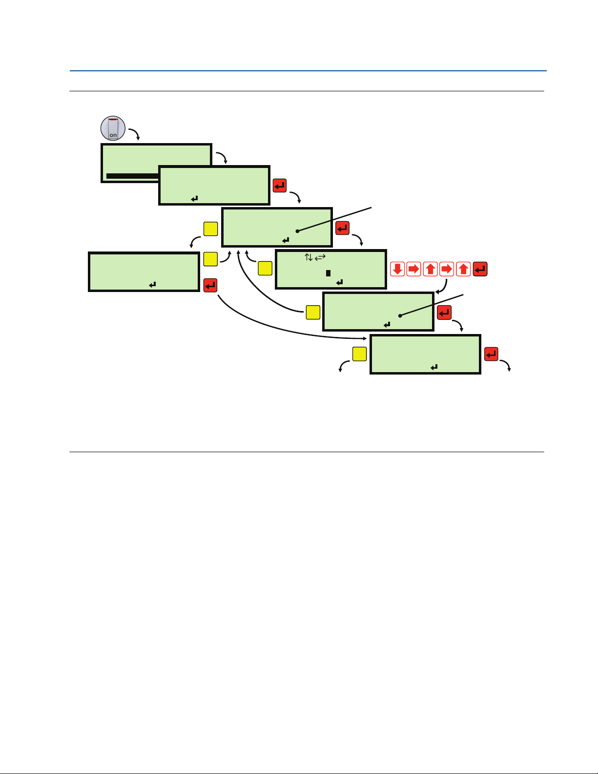
Follow these instructions for a quick tour of the menu system:
1. This quick tour begins at the Full Display or Large PV Display (Figure 4-5 on page 31).
If already within the menu system, use the Esc button repeatedly until the Full Display
re-appears.
2. Press the red (ENTER) button to display the MAIN MENU (see Figure 4-5 on page 31).
The MAIN MENU is the top level of the menu system.
3. Navigation of the menu system is achieved by using the ARROW buttons,
the red (ENTER) button, and the Esc button.
The Esc button returns you to the previous menu level, unless you are at the top level.
4. The highlighted and blinking text indicates what menu option will be selected if the
red (ENTER) button was pressed now. Do not press it yet.
Reference Manual
IP2030/RM, Rev AA
5. The
6. The MAIN MENU sits above a series of sub-menus, which lead to further levels of
7. Press the red (ENTER) button to select the highlighted menu option SETUP.
8. The SELECT INSTRUMENT menu now appears. This screen is for selecting whether to
9. Press the red (ENTER) button to select the highlighted menu option Controller: ****.
10. The control unit SETUP menu now appears with menu options APPLICATION, DISPLAY,
11. Use the DOWN-ARROW button to highlight OUTPUT and then press the red (ENTER)
12. The OUTPUT menu now appears with menu options CURRENT OUTPUT, RELAY,
symbol on the display indicates there are further menu options available,
accessible by using the DOWN-ARROW button.
An
symbol indicates there are further menu options available, accessible by using the
UP-ARROW button.
sub-menus that lead to parameter screens (see Figure 4-6 on page 31).
enter the setup menu for the control unit (controller) or a found HART transmitter.
If there are no HART transmitters connected, Step 7 results in the SETUP menu for the control
unit appearing straight away. Skip to Step 10.
and OUTPUT visible.
button to select and enter the OUTPUT menu.
TOTALIZER, PV DAMPING, ALARM, and FAU LT.
13. Explore these menu options to see screens for setting-up for an application and for
displaying read-only information.
14. After exploring, hold down the Esc button once to return to the MAIN MENU.
Section 4: Getting started30
Page 39

Reference Manual
A
B
MAIN MENU
Run App?
MONITOR
SETUP
SELECT INSTRUMENT
Tx1: ****
Tx2: ****
Controller : ****
MAIN MENU
Run App?
MONITOR
Advanced
SELECT INSTRUMENT
Tx1: ****
Tx2: ****
Controller : ****
ADVANCED
Dxxx
Pxxx
1
1
1
1
1
=
Run App?
= Yes
1
Esc=No
Program?
=Yes
Esc=No
1
Note A
Note B
Note C
Note D
Note E
Note F
or
IP2030/RM, Rev AA
Figure 4-5. How to enter the menu system
1.572m
1
1.572m
SETUP
Run App?
MONITOR
A. Large PV display.
B. Full display showing PV in normal size characters and other information.
Figure 4-6. MAIN MENU overview
12:47
1
Section 4: Getting started
June 2014
MAIN MENU
Section 4: Getting started
A. Toggles the operating mode of the control unit. An open padlock indicates that Program mode is selected and
parameter values can be changed.
B. Selecting Controller: ****leads to the SETUP menu for setting up the control unit for an application.
C. Selecting Tx1: **** leads to the SETUP menu for adjusting the HART transmitter Tx1 operation (and similarly for Tx2
on the Mobrey MCU902). The Transmitter Bottom Reference for Tx1 (and similarly for Tx2) can be changed here.
D. Selecting Controller: **** leads to menus for viewing live readings and diagnostic information for the control unit.
E. Selecting Tx1: **** leads to menus for viewing live readings and diagnostic information from the HART transmitter
Tx1 (and similarly for Tx2 on the Mobrey MCU902).
F. Advanced access menu for advanced users to directly select parameter screens when the parameter number is
known. For a guide to this, see Appendix D Additional Features.
31
Page 40

Section 4: Getting started
June 2014
4.5 Programming the control unit
4.5.1 The basics
This chapter covers programming using the front panel of the MCU900 Series control unit to
make changes to the factory default set-up of the control unit.
Use the Application Wizard (App Wizard) to easily set-up the control unit for a level, flow, or
contents volume application, and then optionally adjust the set-up by editing parameters in the
menu system. See Appendix C: Menus and Parameters for a full list of menus and parameters.
Note
If a Mobrey MSP Series transmitter is connected, refer to the reference manual of the
transmitter for full information about programming the transmitter parameters
(e.g. Transmitter Bottom Reference) using the MCU900 Series control unit or other
HART-based devices.
For information about how the control unit supports other HART transmitters, see
Appendix C: Menus and Parameters and Appendix E: Support for HART® Transmitters.
Reference Manual
IP2030/RM, Rev AA
The basics about parameters
The MCU900 Series control unit has menu-based parameters for programming – setting up for
an application, adjusting default settings, etc. – and for viewing information.
Parameters are populated throughout the menu system. They are grouped in sub-menus, which
are organized for intuitive programming. Each parameter has a unique 3-digit identification
number, prefixed by a 'P' (if programmable) or a 'D' (if for display purposes only).
Note
A full list of menus and parameters is in Appendix C: Menus and Parameters
With some experience, it becomes easy to locate parameters. Alternatively, parameters can be
accessed directly by entering their unique 3-digit identification number. Details of this
Advanced access feature are in Appendix D: Additional Features.
To understand the basics about editing a parameter setting, follow the worked examples for
editing a numerical parameter and the calendar date parameter.
Section 4: Getting started32
Page 41
Reference Manual
x3
x2
Note A
IP2030/RM, Rev AA
Section 4: Getting started
June 2014
How to edit a numerical parameter
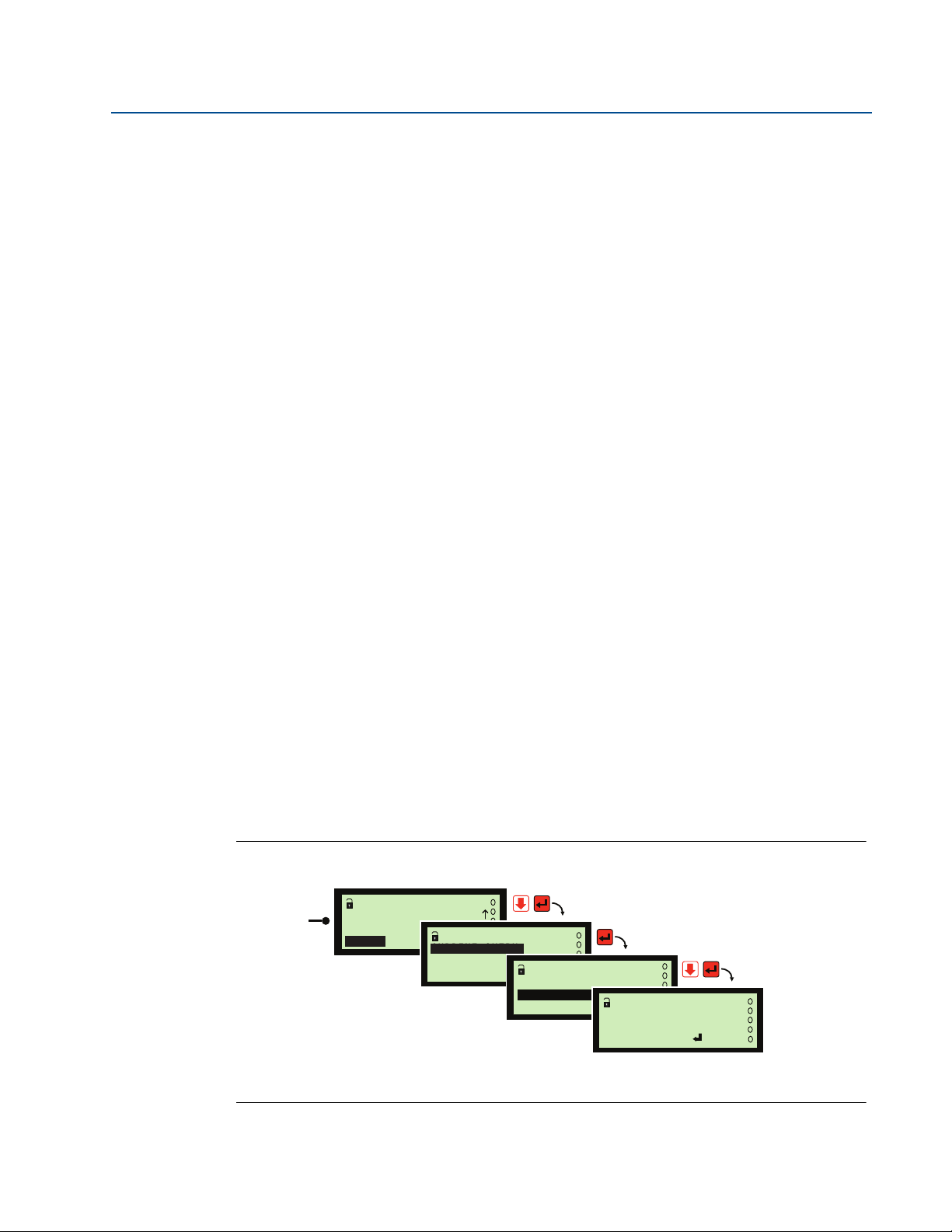
1. Navigate to the Up Range Value parameter screen (see Figure 4-7).
2. When entering any parameter screen, it is in View Mode (Figure 4-8 on page 34).
Help with what can be done next is on display line 4.
(In View Mode, the Esc button is used to leave (quit) the parameter screen.
The SETTINGS menu then re-appears, as seen before selecting the parameter screen).
3. To enter Edit Mode, press the red (ENTER).
4. A highlighted “+” appears (Figure 4-8) to show this positive sign can be changed to be a
negative sign. The UP-ARROW or DOWN-ARROW cycles between “+” and “–”.
(Also, note that on display line 4, “Edit” has changed to be “Save”).
5. Change the number from “+12.000” to “+6.500” (Figure 4-8):
a. Press the RIGHT-ARROW button once to move right one space and highlight the “1”.
(The LEFT-ARROW can be used to move the highlight back one space).
b. Press the UP-ARROW button five times to change the “1” to a “6”.
(The DOWN-ARROW can be used to scroll down through the numbers and decimal point).
c. Press the RIGHT-ARROW button once to highlight the “2”.
d. Press the DOWN-ARROW button three times to change the “2” to a decimal point.
e. Press the RIGHT-ARROW button once to highlight the old decimal point.
f. Press the DOWN-ARROW button six times to change the old decimal point to a “5”.
(Note that other button press sequences could have been used to edit 6.500).
6. Press the red (ENTER) button to save the +6.500 and return to View Mode
that on display line 4, “Save” has changed back to “Edit”).
e
(Not
7. Press the Esc button to return to the SETTINGS menu.
Figure 4-7. Navigation to a numerical parameter screen
SETUP
CURRENT OUTPUT
CURRENT OUTPUT
RELAY
TOTALIZER
OUTPUT
Low Range Val
Up Range Val
Alarm Action
CURRENT OUTPUT
Up Range Val P401
12.000 m
Esc=Quit =Edit
APPLICATION
DISPLAY
OUTPUT
.
Section 4: Getting started
A. This is the SETUP menu for the control unit – see Figure 4-6 on page 31 for how to get here.
33
Page 42

Section 4: Getting started
Note A
Note B
Note D
Note C
June 2014
Figure 4-8. Example of editing a numerical value
Up Range Val P401
12.000 m
Esc=Quit =Edit
Up Range Val P401
12.000 m
+
Esc=Quit =Save
Up Range Val P401
+12.000 m
Esc=Quit =Save
1
Up Range Val P401
+62.000 m
Esc=Quit =Save
6
Up Range Val P401
+6..000 m
Esc=Quit =Save
Reference Manual
IP2030/RM, Rev AA
.
Up Range Val P401
+6.5000 m
Esc=Quit =Save
A. When entering any parameter screen, it is in View Mode. Help with what can be done next is on display line 4.
B. Parameter is in Edit Mode. In this mode, pressing Esc button restores the original setting and returns to View Mode.
C. The UP-ARROW button is used to scroll up through the numbers and decimal point, and the DOWN-ARROW button
scrolls down through the numbers and decimal point.
D. Parameter has returned to View Mode.
5
Up Range Val P401
6.5000 m
Esc=Quit =Edit
How to edit the calendar date parameter
1. Navigate to the Date parameter screen (see Figure 4-9 on page 35).
2. When entering any parameter screen, it is in View Mode (Figure 4-10 on page 35).
Help with what can be done next is on display line 4.
(In View Mode, the Esc button is used to leave (quit) the parameter screen.
The SETTINGS menu then re-appears, as seen before selecting the parameter screen).
3. To enter Edit Mode, press the red (ENTER) button.
4. The “3” is highlighted to show this digit can now be edited (Figure 4-10).
(Also, note that on display line 4, “Edit” has changed to be “Save”).
5. Change the calendar date from “30/01/14” to “31/01/14”:
a. Press the RIGHT-ARROW button once to move right one space and highlight the “0”.
(The LEFT-ARROW can be used to move the highlight back one space).
Section 4: Getting started34
Page 43

Reference Manual
SETUP
INPUT CHANNEL
DIGITAL INPUT
SYSTEM
SYSTEM
TEST
DEFAULTS
SETTINGS
SETTINGS
Time
Date Format
Date
Date P730
30/01/14dmy
Esc=Quit =Edit
x5
Note A
Date P
30/01/14dmy
Quit
=
730
Esc= Edit
Date P
30/01/14dmy
Quit
=
730
Esc= Save
Date P
31/01/14dmy
Quit
=
730
Esc= Save
3
1
Date P
31/01/14dmy
Quit
=
730
Esc= Edit
Note A
Note B
Note D
Note C
IP2030/RM, Rev AA
Section 4: Getting started
June 2014
b. Press the UP-ARROW button once to change the “0” to a “1”.
(The DOWN-ARROW can be used to cycle backwards through the digits and decimal point).
6. Press the red (ENTER) button to save the new date and return to View Mode.
(Note that on display line 4, “Save” has changed back to “Edit”).
7. Press the Esc button to return to the SETTINGS menu.
Figure 4-9. Navigation to the calendar date screen
A. This is the SETUP menu for the control unit – see Figure 4-6 on page 31 for how to get here.
Figure 4-10. Example of editing the calendar date
A. When entering any parameter screen, it is in View Mode. Help with what can be done next is on display line 4.
B. Parameter is in Edit Mode. In this mode, pressing Esc button restores the original setting and returns to View Mode.
C. The UP-ARROW button is used to scroll up through the numbers and decimal point, and the DOWN-ARROW button
scrolls down through the numbers and decimal point.
D. Parameter has returned to View Mode.
Section 4: Getting started
35
Page 44
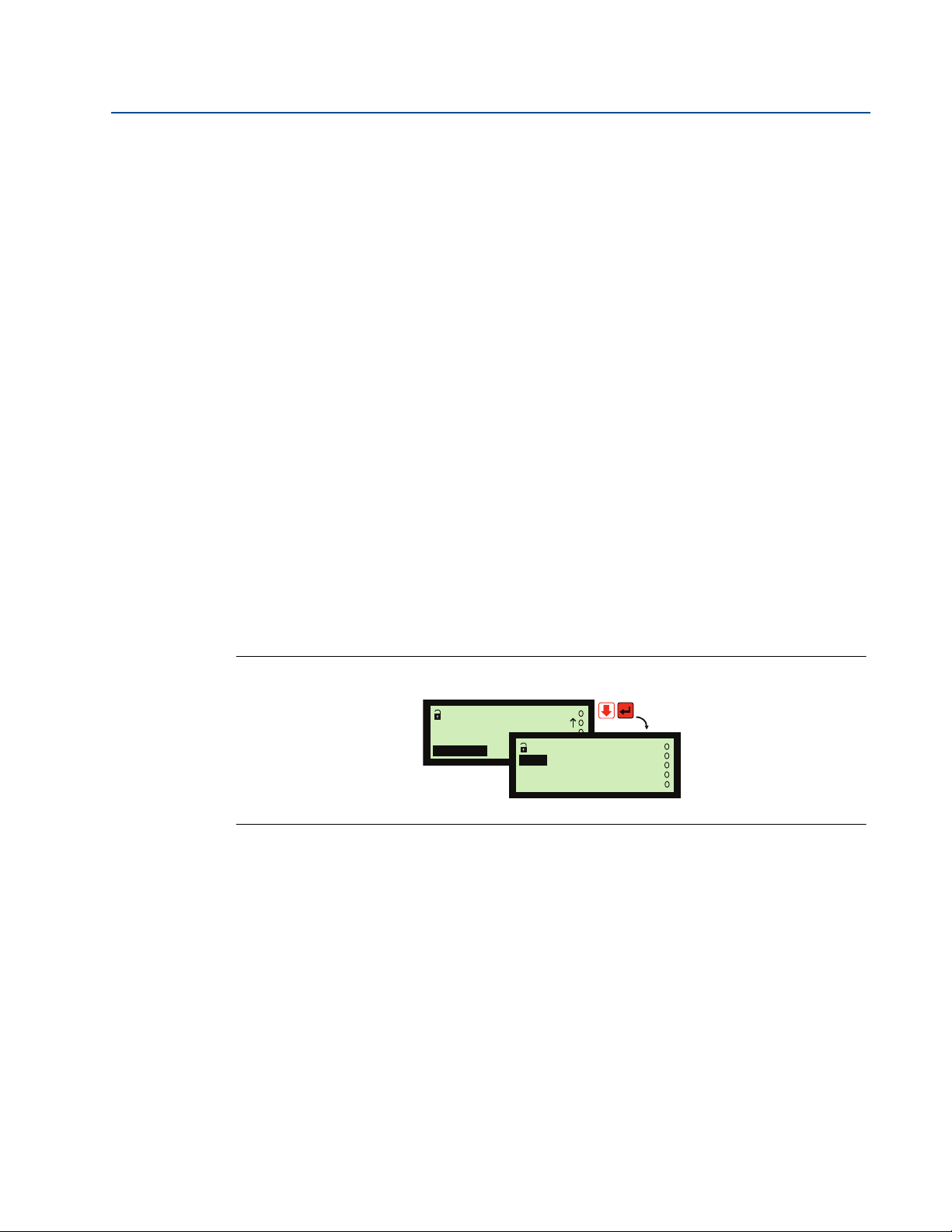
Section 4: Getting started
MAIN MENU
Run App?
MONITOR
ADVANCED
ADVANCED
Dxxx
Pxxx
x3
June 2014
The basics about the menu navigation
In this chapter and throughout this manual, a simple notation has been used to guide you to a
particular menu screen or parameter screen. This avoids the need for detailed navigation
instructions.
Consider the navigation instructions to be followed before arriving at the ADVANCED menu.
For the purpose of this example, the starting point is the Full PV Display.
In the notation form, this is simply:
1. Navigate to MAIN MENU / ADVANCED
Without the notation, this translates into these instructions:
1. Press the red (ENTER) button to display the MAIN MENU screen.
2. Press the DOWN-ARROW button three times until ADVANCED is highlighted and
3. Press the red (ENTER) button once.
Reference Manual
IP2030/RM, Rev AA
blinking.
If square brackets are used in the notation, e.g. MAIN MENU / SETUP / [CONTROL UNIT], it
signifies that the bracketed menu does not appear in all circumstances.
When HART transmitters are not being used, the SELECT INSTRUMENT screen does not appear.
As there is no need to select the control unit menu or a HART transmitter (Tx1 or Tx2) menu, the
menus that appear after selecting MAIN MENU / SETUP are purely for the control unit.
Figure 4-11. Navigating to the ADVANCED menu
Section 4: Getting started36
Page 45

Reference Manual
IP2030/RM, Rev AA
Section 4: Getting started
4.5.2 Step-by-step programming of the control unit
Step 1: Put the unit into Program mode
Put the control unit into Program mode. (The factory default is for it to be in Program mode).
See “Run App and Program operating modes” on page 38.
Step 2: Use the App Wizard
Use the Application Wizard (App Wizard) to easily set-up the control unit for a level, flow, or
contents volume application, and then optionally adjust the set-up by editing parameters in the
menu system. For examples of using the App Wizard, see“Application Wizard” on page 39.
Note:
Before using the App Wizard with a 4–20 mA transmitter, the Input Channel 1 source
parameter P111 on the control unit must be set for a 4–20 mA input (see page 44)
Level and volume measurement duties are not available on the MCU90F Logging unit.
June 2014
Step 3: Optional changes after using the App Wizard
Optionally change system settings
This includes how to switch on the keyboard sound, setting the date/time, and changing
language. See “Optional change: system settings” on page 42.
Optionally change transmitter input channel settings (advanced users)
This is for advanced users and looks in-depth at how the input channels are used to obtain the
control unit Process Value / Primary Value (PV) value from a transmitter.
See “Optional change: transmitter input channel settings (advanced users)” on page 43
For most users, the App Wizard will set-up the majority of applications with no need of
direct changes to input channel parameters.
Optionally change application settings (advanced users)
This is for advanced users and looks in-depth at further processing of PV values to get content
(volume) or flow rate values, which can be shown on the display. A totalizer function can also be
set-up. For most users, the App Wizard will set-up the majority of applications with no
need of direct changes to application parameters.
See “Volumetric contents and flow measurement applications (advanced users)” on page 52
and “Using a plotted profile for calculating volume or flow” on page 61.
Section 4: Getting started
Optionally change the digital input settings
This includes how to allocate actions to digital inputs (IN1 and IN2).
See “Digital inputs IN1 and IN2” on page 63.
Optionally change output settings
This includes setting-up the 4–20mA output and relay outputs.
See “Set-up the current output” on page 68 and “Set-up the relays” on page 69.
37
Page 46

Section 4: Getting started
Program?
= Yes
Esc=No
1
=
Run App?
= Yes
1
Esc=No
MAIN MENU
Run App?
SETUP
MONITOR
Run App?
1
MAIN MENU
Run App?
SETUP
MONITOR
Program?
1
MAIN MENU
Program?
SETUP
MONITOR
SETUP
1
MAIN MENU
Program?
SETUP
MONITOR
SETUP
1
Switching to Run App mode: Switching to Program mode:
June 2014
Optionally set-up other features
This includes configuring data logging (page 64), alarm handling (page 91), the display
(page 102), serial communications (page 104), and PIN security (page 105).
By default, security restrictions are switched off and the user has access to all parameters.
After programming (configuring) is complete, a PIN security code can be used to prevent
unauthorized access. For details, refer to Section “PIN Security” on page 105.
Step 4: Put the unit into Run App mode
Put the control into Run App mode (see below).
For checks e.g. auto-cycle of the control unit Primary / Process Value (PV), diagnostics, and
fault-finding, see Section 5: Servicing and Health Checking.
There is trouble-shooting information in Section 5: Servicing and Health Checking.
Alternatively, the MCU900 Series control unit can be re-set to the factory defaults as guided in
the Section “Restoring the factory defaults” on page 135.
Reference Manual
IP2030/RM, Rev AA
4.5.3 Run App and Program operating modes
Menu: MAIN MENU / Run App? (or MAIN MENU / Program?)
There are two operating modes on the control unit: Run App and Program.
Press the red (ENTER) button at the Run App? or Program? screen to switch between these
two operating modes (Figure 4-12)
An open padlock icon indicates the MCU900 Series control unit is presently in the Program
mode.
In this mode, the unit can be programmed. The Current Output and all Relay Outputs are frozen
unless allocated to totalizing and sampler duties. Fault relays are de-energized.
A closed padlock icon indicates that the MCU900 Series control unit is presently in the Run App
mode. In this mode, most of the unit cannot be programmed. The Current Output and all Relay
Outputs operate as normal.
The Program? screen (Figure 4-12) appears automatically if an attempt is made to edit a
parameter whilst in Run App mode. A security PIN can be set-up to restrict the mode change.
Figure 4-12. How to switch between Run App and Program modes
Section 4: Getting started38
Page 47
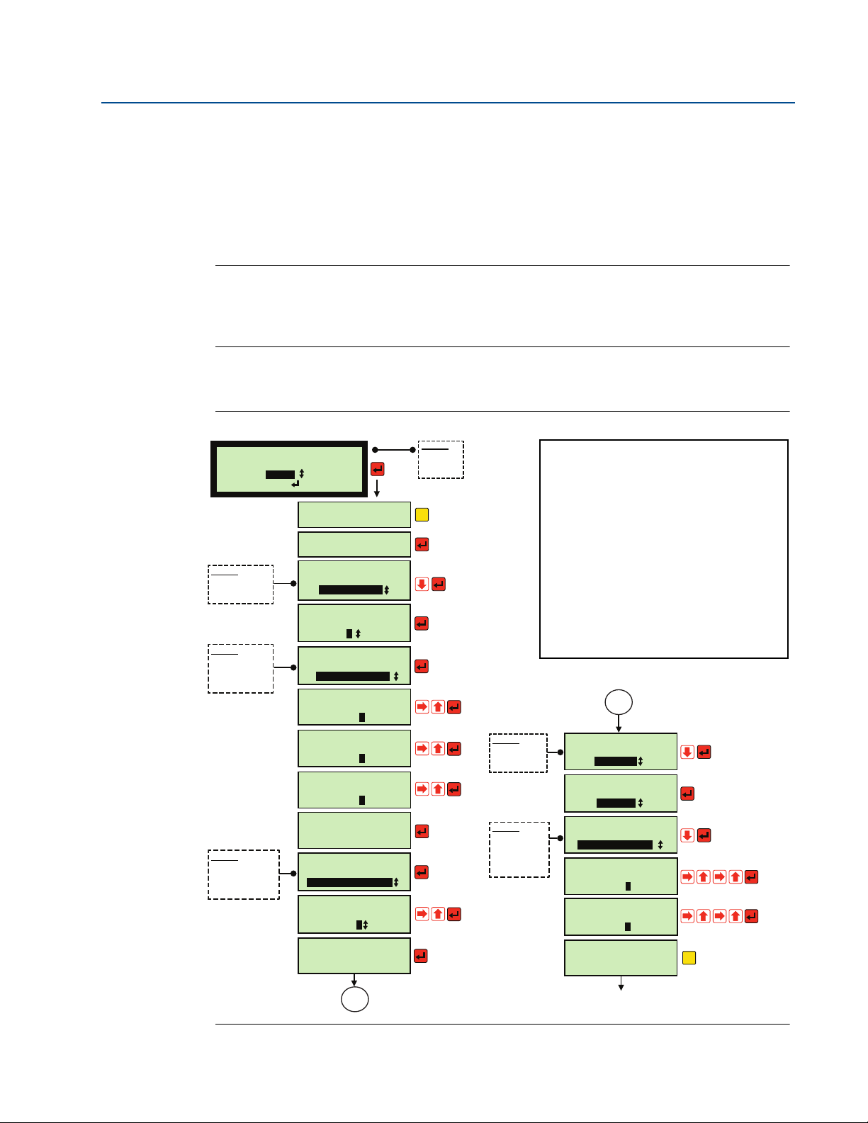
Reference Manual
App Wizard
Select Application
Esc=Back =Next
Level
Options:
* Level
* Volume
* Flow
Set Current Output ?
Set up Relays ?
Relay Wizard
Select Function
Pump Control
Options
*
Relay(s)
*
Pump Control
*
Custom
Select Mode for
Relay 3
Hi or Lo Alarm
Options
*
*
Rate of change
*
Out of limits
*
Digital input
Enter On point
for Relay 3
000012 ft
Enter Off point
for Relay 3
000011 ft
1
2
Set point
*
Hi or Lo Alarm
Setup Complete
Program further
Relays?
Pump Control
Number of Pumps
2
Options
*
Assist com off
*
Assist split off
*
Stby com off
*
Stby split off
Select Pump Control
Duty
Assist com off
Number of starts
Qualifier
00
4
Options
*
Number of starts
*
Run-Time
*
Ratio of Run-Time
*
Ratio of starts
Select
Autosequence on
t
Number of starts
Enter On point
for Pump 1
000000 ft
5
Enter On point
for Pump 2
000000 ft
8
Lowest common
off point
000000 ft
1
Pump Control
Select
Autosequence Mode ?
Relay Wizard
Select Function
Relay(s)
Relay(s)
Select Relay
Relay 3
Options
*
Relay(s)
*
Pump Control
*
Custom
Setup Complete
Program further
Relays?
Esc
Esc
APPLICATION DATA
INPUTS:
Level measurement in feet from transmitter.
Transmitter Bottom Reference is 22 ft.
Sump/lift station working level is 20 ft.
2-pump operation required is duty assist with
common off. Auto-sequencing after 4 starts.
OUTPUTS:
Level in feet.
Relay 1 (Pump 1) on at 5 ft.; off at 1 ft.
Relay 2 (Pump 2) on at 8 ft.; off at 1 ft.
Relay 3 (High Alarm) on at 12 ft.; off at 11 ft.
x5
x8
x4
x5
x5
x5
x4
x4
x2
(no)
(yes)
(Pump
control)
(2)
(Assist
com off)
(5)
(5)
(1)
(yes)
(Number
of starts)
(4)
(yes)
A
A
(Relays)
(Relay 3)
(Hi or Lo
Alarm)
(12)
(11)
(no)
x2
Exits to menu system.
(Select Run App mode to start application).
IP2030/RM, Rev AA
4.5.4 Application Wizard
Use the Application Wizard (App Wizard) to easily set-up the control unit for an application.
If a message appears saying that the units are not set, it is because the HART transmitter has not
been found by the control unit when power was applied. Change the operating mode from
Program to Run App mode and the control unit will attempt to re-connect to the transmitter.
Note
When using a MCU902 control unit, it is necessary to select Difference, Sum, Product,
or Independent (and channel) before Level/Volume/Flow can be selected.
Level and volume measurement duties are not available on the MCU90F Logging unit.
Using the App Wizard to set-up a level application
Figure 4-13. App Wizard example: pump control with a high alarm
Section 4: Getting started
June 2014
Section 4: Getting started
39
Page 48

Section 4: Getting started
App Wizard
Select Application
Esc=Back =Next
Volume
Options:
* Level
* Volume
* Flow
Volume Wizard
Select Tank Shape
Horiz cyl flat
Options
* Vertical cylinder
* Horiz Cyl flat
* Horiz Cyl domed
* Rectangular
* Spherical
* Conical bottom
* 20 point table
(Wait while transferring plot points)
Choose method of
calibrating Tank
Tank dimensions
Options
*
Tank dimensions
*
Maximum volume
Enter value
of Tank diameter
6.5000 ft
5
Enter value
of Tank Length
255000 ft
.
Volume Wizard
max Tank Volume
6205.6 gal
Set Current Output ?
Enter volume
to give 4 mA out
000000 gal
Enter volume
to give 20 mA out
6200.0 gal
0
Set up Relays ?
Relay Wizard
Select Function
Relay(s)
Options
*
Relay(s)
*
Pump Control
*
Custom
Options
*
Relay 1
*
Relay 2
*
Relay 3
*
Relay 4
Select Mode for
Relay 1
Hi or Lo Alarm
Options
*
*
Rate of change
Relay(s)
Select Relay
Relay 1
*
Out of limits
*
Digital input
*
Hi or Lo Alarm
Enter On point
for Relay 1
006000 gal
Enter Off point
for Relay 1
005800 gal
8
6
Set point
Setup Complete
Program further
Relays?
Esc
0
APPLICATION DATA
INPUTS:
Level measurement in feet from transmitter.
Transmitter Bottom Reference is 7.5 ft.
Tank is a horizontal cylinder with flat ends.
Tank dimensions are 6.5 ft. dia. x 25 ft. length.
Volume capacity is 6205.6 gallons.
OUTPUTS:
Contents volume in US gallons displayed.
Relay on at 6000 gallons; off at 5800 gallons.
Current Output range 0 to 6200 gallons.
x6
x5
x2
x5
x5
x6
x6
x5
x8
x2
x2
x3
(Horiz
cyl flat)
(Tank
dimensions)
(continue)
(6.5)
(25.0)
(yes)
(0)
(Edits 6205.6 to be 6200.0)
(yes)
(Relays)
(Hi or Lo Alarm)
(6000)
(5800)
(no)
Exits to menu system.
(Select Run App mode
to start application).
(Relay 1)
x2
June 2014
Reference Manual
IP2030/RM, Rev AA
Using the App Wizard to set-up a contents volume application
Figure 4-14. App Wizard example: tank volume with a high alarm
Section 4: Getting started40
Page 49
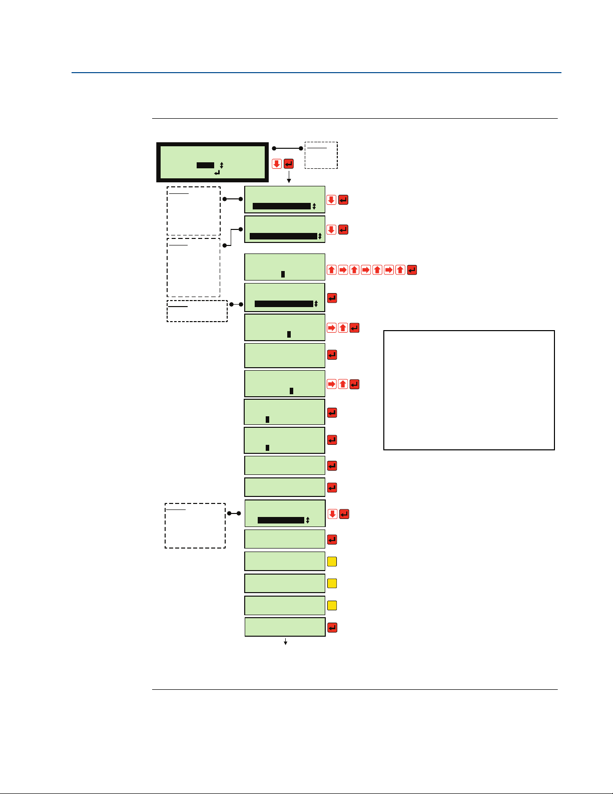
Reference Manual
App Wizard
Select Application
Esc=Back =Next
Flow
Options:
* Level
* Volume
* Flow
Flow Wizard
Select Output Units
gallons per min
Options
*
gallons per day
*
gallons per hour
*
gallons per min
*
Mega gals / day
*
Cubic ft per hour
*
Cubic ft per sec
Flow Wizard
Select Profile
V-Notch Weir (5/2)
Options
*
Flow Calculation
*
Flume/Weir (3/2)
*
V-Notch Weir (5/2)
*
V-Notch (ISO1438)
*
Vlarem
*
Parshall
*
Manning
*
20 point look-up
Enter max
flow
645.50 g/m
5
Enter height for
max flow
000001 ft
1
Enter flow
to give 4 mA out
000000 g/m
Enter flow
to give 20 mA out
645.50 g/m
6
Do you wish
to set up a
low flow cut off ?
(Wait while transferring plot points)
Choose method of
calibrating flow
HT for max flow
Options
*
Height for max flow
*
Flow at present height
Enter
low flow cut off
000001 %
2
Flow Wizard
complete
Totalizer Wizard
complete
Set up totalizer?
Display totalizer?
Set up Totalizer
relay?
Set up Sampler
relay?
Totalizer Wizard
Select Units
gallons x100
Options
*
gallons
*
gallons x10
*
gallons x100
*
gallons x1000
*
million gallons
*
cubic feet
Esc
Esc
Inhibit Totalizer
on digital input(s)?
Esc
0
APPLICATION DATA
INPUTS:
Level measurement in feet from transmitter.
Open channel is a 60° V-Notch Weir
Maximum flow is 645.50 gallons per minute.
Height at maximum flow is 1 ft.
OUTPUTS:
Flow rate in gallons per minute
Totalized flow in gallons x 100
2% low flow cut-off
x2
x2
x2
x5
(Edits 100.0 to be 645.5)
x4
x5
x5
x5
x5
x2
x2
(gallons per min)
(V-Notch Weir 5/2)
(Height for max flow)
(1)
(yes)
(2)
(0)
(645.50)
(continue)
(yes)
(gallons)
(yes)
(no)
(no)
(no)
(continue)
Exits to menu system.
(Select Run App mode
to start application).
x2
IP2030/RM, Rev AA
Section 4: Getting started
Using the App Wizard to set-up a flow application
Figure 4-15. App Wizard example: open channel flow with a 60° V-Notch Weir
June 2014
Section 4: Getting started
41
Page 50

Section 4: Getting started
June 2014
4.5.5 Optional change: system settings
Menu: SETUP / [CONTROLLER /] SYSTEM / SETTINGS
Calendar clock
P730 Date
Set the calendar date in the format as selected by P734.
P731 Time
Set the clock time. The 24-hour clock format is supported.
P734 Date format (Default setting is "dd/mm/yy")
Choose between “dd/mm/yy”, “yy/mm/dd”, and “mm/dd/yy”.
Keypad sound
P735 Keypad Sound (Default setting is “Off”)
Reference Manual
IP2030/RM, Rev AA
If you want the keypad sound switched on, select “On” from the option list.
Language
P737 Language (Default setting is "English")
If you wish to change the language used on-screen, there is a choice of other languages.
Section 4: Getting started42
Page 51

Reference Manual
IP2030/RM, Rev AA
Section 4: Getting started
4.5.6 Optional change: transmitter input channel settings (advanced users)
Sections 4.5.6 to 4.5.9 are for advanced users. They explain in-depth what transmitter inputs
are supported on the control unit, and how to program (configure) the operation of those
transmitter inputs to result in a control unit Primary / Process Value (PV).
The resulting control unit PV is indicated on the factory-default configured display.
For most users, the App Wizard will set-up the majority of applications with no need of
direct changes to input channel parameters.
Transmitter input channels on the Mobrey MCU901 and MCU90F
The MCU901 and MCU90F control units support the connection of a single 4–20 mA or HART
transmitter. There is one transmitter input channel and it is referred to as Input Channel 1.
For a 4–20 mA transmitter:
See “Programming Input Channel 1 for a 4–20 mA input (advanced users)” on page 44.
June 2014
For a HART transmitter:
See “Programming Channel 1 for a HART input (advanced users)” on page 48.
Transmitter input channels on the Mobrey MCU902
The MCU902 control unit supports the connection of two HART transmitters, but not two 4–20
mA transmitters. The input channels and are referred to as Input Channel 1 and Input Channel
2.
For two HART transmitters:
See “Programming Channel 1 for a HART input (advanced users)” on page 48.
See “Programming Channel 2 for a HART input (MCU902 only) (advanced users)” on
page 50
Sum, difference, or product calculations using input channels 1 and 2
Parameter P150 selects how final values from transmitter input channels 1 (D851) and 2 (D852)
are processed together – sum, difference, or product calculation – before being output to
parameters D800, D801, D802, or D803 ('Answers').
The factory default programming (configuration) for P150 is to allow values from D851 to go
straight to D800.
For a graphical overview, see Figure 4-17 and Figure 4-18 on page 47.
.
Section 4: Getting started
43
Page 52

Section 4: Getting started
June 2014
Reference Manual
IP2030/RM, Rev AA
4.5.7 Programming Input Channel 1 for a 4–20 mA input (advanced users)
This section explains how to program (configure) the operation of the Input Channel 1 on the
control unit when a 4–20 mA transmitter is connected. Do not connect a second transmitter.
Please read this section together with the graphical overview in Figure 4-16 on page 47.
The final result of the Input Channel 1 processing is stored in D800 and is referred to as the
control unit Primary / Process Value (PV). It is shown on the factory default configuration of
the display.
Essential parameters to program
Select the displayed units for the control unit Primary/ Process Value (PV)
First, it is essential to know the units for the measurements coming from the transmitter.
When this is known, navigate the menu system to SETUP / [CONTROLLER /] DISPLAY / PV Units
for the PV Units parameter P200 and then select the measurement units that are to be shown
for the control unit PV on the display.
Please note that the PV Units parameter (P200) does not automatically convert the transmitter
input or the control unit PV into alternative units. It is necessary to enter a conversion factor into
parameter P114 (see the descriptions that follow).
Set Input Channel 1 to receive input from a 4–20 mA transmitter
1. Navigate to the menu SETUP / [CONTROLLER /] INPUT CHANNEL / Ch1 I/P Source for
the Ch1 I/P Source parameter P111.
2. Select mA in 1 from the option list.
Note
The built-in Application (App) Wizard is an easy-to-use configuration tool that can be
used to automatically populate values and settings in the input channel parameters.
Navigate to: SETUP / [CONTROLLER /] APPLICATION / App Wizard
Before using the App Wizard with a 4–20 mA transmitter, the Input Channel 1 source
parameter P111 on the control unit must be set for a 4–20 mA signal input; this is not
the factory default setting for P111.
Optional parameters and how the 4–20 mA signal is processed
Figure 4-16 on page 47 shows how the 4–20 mA input signal is processed through Input
Channel 1 and which parameters and processing stages affect the resulting control unit PV.
Signal conditioning and damping stages
Analog measurements (level, pressure, and temperature, etc.) are input to the control unit as a
4–20 mA signal, and pass through a conditioning stage (to remove spikes) and a damping stage
(to smooth out large jumps in signals).
The damping can be adjusted by changing the time setting (in seconds) in parameter P321.
Navigate to the menu SETUP / [CONTROLLER /] INPUT CHANNEL / Cur I/P Damping.
Section 4: Getting started44
Page 53

Reference Manual
IP2030/RM, Rev AA
Section 4: Getting started
June 2014
Signal limits check
The signal is then checked to ensure it is within the range of 3.7 to 20.75 mA. Signals outside
this range cause an alarm condition, which may be externally signalled using a control unit relay
(see “Alarm indication selection” on page 91).
Conversion of signal into a percentage value
By default, the mA signal (readable via D840) is converted (normalized) into a percentage in the
range 0 to 100% (readable via D842), where 4 mA is 0% and 20 mA is 100%.
Note
The control unit can process mA input values in the range 3.8 to 20.5 mA
Read-only parameters D840 and D842 are in the menu MONITOR / DIAGNOSTICS
Applying the optional percentage offset adjustment
P112 is a positive, negative, or zero offset adjustment of the converted (normalized)
percentage. This optional offset feature can be used to accommodate a standing level in a tank.
Note
The output from this adjustment is readable in D802 and is the Tertiary Value (TV) of
the control unit. D802 = D842 + P112
P112 is in the menu SETUP / [CONTROLLER /] INPUT CHANNEL / Ch1 I/P Offset
Applying the scaling factor to get the required units
Changing the PV display units (P200) does not automatically convert the control unit PV to be in
alternative units. A user-entered value in P114 is used to convert (scale) the offset-adjusted
percentage value (D802) to a new value (D801) that is in the required measurement units.
If the mA input represents a liquid level, simply set P114 to the level represented by 20 mA.
Note
D801 is the Secondary Value (SV) of the control unit. D801 = (D802/100) * P114
P114 is not applied if the PV display units (P200) are already configured to be “%”
P114 is in the menu SETUP / [CONTROLLER /] INPUT CHANNEL / Ch1 Pre Scale
Read-only parameters D80* are in the menu MONITOR / READINGS
Optional calculation of contents (volumetric) or flow measurement
By selecting a vessel profile or calculation using P113, a level measurement in D801 can be used
to calculate a volume measurement or open channel flow rate that is then stored in D851.
The programming (configuring) required for this is in “Volumetric contents and flow
measurement applications (advanced users)” on page 52.
Section 4: Getting started
Applying an optional low volume or flow rate cut-off action
The channel 1 output result in D851 can be forced to zero when it falls below a positive
threshold, which is a percentage of the maximum flow. Enter the percentage in P117.
By default, the setting is “None” to switch off this optional check.
45
Page 54

Section 4: Getting started
June 2014
This feature is particularly useful in an open channel flow application where a small standing or
remaining liquid level in the channel would cause continued totalizing of flow when no actual
flow exists. As a guide, set P117 to a positive value of 2% of maximum flow to overcome this
problem.
Note
P117 is in the menu SETUP / [CONTROLLER /] INPUT CHANNEL / Ch1 Low Cut-off
Applying optional damping to the control unit PV
P210 allows the to smooth out large steps in calculated values (D851).
Note
P210 is in the menu:
D851 is in the menu:
Reference Manual
IP2030/RM, Rev AA
SETUP / [CONTROLLER /] OUTPUT / PV DAMPING / MCU PV DAMPING
MONITOR / DIAGNOSTICS / CHANNELS / Ch1 Output
Section 4: Getting started46
Page 55
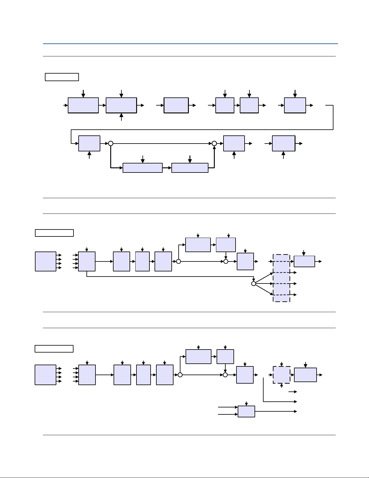
Reference Manual
Conditioning
and damping
mA Input
P321
Normalise
mA to %
Input
Source
Select
P111
D842
mA mA
%%
Apply
Input
Offset
P112
Channel
Profile
Select
D802
(TV)
D840
Apply
Input
Scaling
P114
%%%
mA
D801
(SV)
P113
Low
Cut-off
Check
Scaled
Profiles
Non-Linear Profile Post Scale NLP
(PV)
D800
4-20mA Limit
Alarm Check
<3.7mA
>20.75mA
P117
P115 P116
D851
(CH1 O/P)
P111 = “mA in”
PV
Damping
P210
Note:
Optional damping of mA readings ten times a second: mA = [mA_before + ((mAnow - mA_before)/(1+10 * P321))]
Optional damping of control unit PV ten times a second: D800 = [D800before + ((D800now - D800before)/(1+10 * P210))]
Input
Source
Select
P111
D900
Txr
HART
Variables
D901
D902
D903
PV, SV,
TV or FV
P112
Apply
Input
Offset
P114
Apply
Input
Scale
(SV)
D801
(TV)
D802
(FV)
D803
SV, TV and FV
Low
Cut-off
Check
D800
Profile
Select
P113
Scaled
Profiles
Non-Linear
Profile
Post
Scale
NLP
(PV)
Output
Map
P117
SV
P115 P116
TV
FV
D851
(CH1 O/P)
P111 = “Tx1 : PV”
PV
Damping
P210
Note:
Optional damping of control unit PV ten times a second:
D800 = [D800before + ((D800now - D800before)/(1+10 * P210))]
Input
Source
Select
P121
D900
Txr (Tx2)
HART
Variables
D901
D902
D903
PV, SV,
TV or FV
P122
Apply
Input
Offset
P124
Apply
Input
Scale
(SV)
D801
(TV)
D802
(FV)
D803
Low
Cut-off
Check
D800
Profile
Select
P123
Scaled
Profiles
Non-Linear
Profile
Post
Scale
NLP
(PV)
P127
P150
D851
(CH1 O/P)
P125 P126
D852
(CH2 O/P)
FV
Select
Tx1
Tx2
PV, SV,
TV and FV
PV, SV,
TV and FV
P151
PV
Damping
P210
P121 = “Tx2 : PV”
Note:
Optional damping of control unit PV ten times a second:
D800 = [D800before + ((D800now - D800before)/(1+10 * P210))]
IP2030/RM, Rev AA
Figure 4-16. Transmitter Input Channel 1 for a 4–20 mA input
Section 4: Getting started
June 2014
Figure 4-17. Transmitter Input Channel 1 for a HART input
Figure 4-18. Transmitter Input Channel 2 for a HART input
Section 4: Getting started
47
Page 56

Section 4: Getting started
June 2014
Reference Manual
IP2030/RM, Rev AA
4.5.8 Programming Channel 1 for a HART input (advanced users)
This section explains how to program (configure) the operation of the Input Channel 1 on the
control unit when a HART transmitter is connected. Read this section together with the
graphical overview in Figure 4-17 on page 47.
Note
Parameters from the HART transmitter are available on the control unit from the SETUP
and MONITOR menus, selectable from the main menu.
Essential parameter to program
Set Input Channel 1 to receive HART digital data from a transmitter
1. Navigate to the Ch1 I/P Source parameter P111:
SETUP / [CONTROLLER /] INPUT CHANNEL / Ch1 I/P Source (on MCU901/3)
SETUP / [CONTROLLER /] PV CALCULATION / CHANNEL 1 / Ch1 I/P Source (on MCU902)
2. Select Tx1: PV from the option list.
Note
The built-in Application (App) Wizard is an easy-to-use configuration tool that can be
used to automatically populate values and settings in the input channel parameters.
Navigate to: SETUP / [CONTROLLER /] APPLICATION / App Wizard
Before using the App Wizard, the Input Channel 1 parameter P111 on the control unit
must be set for a HART input. This is the factory default setting for P111.
Optional parameters and how the HART data is processed
Figure 4-17 on page 47 shows how the HART data is processed through Input Channel 1 and
shows which parameters and processing stages affect the result from Input Channel 1.
HART digital data is continuously read from the transmitter
The HART transmitter digitally communicates pre-calculated values of four HART variables
Primary Variable (PV), Secondary Variable (SV), Tertiary Variable (TV), and Fourth Variable (FV)
to the MCU900 Series control unit.
Selection of a HART variable as source for further processing
Parameter P111 selects one of the four HART variables (PV, SV, TV, or FV) on the transmitter to
be the source for further processing to get a result from Input Channel 1. The un-selected HART
variables are mapped to control unit D80x parameters (see Figure 4-17 on page 47).
Note
In Figure 4-17 on page 47, the selected source is the HART Primary Variable (PV).
Alternatively, Tx1: SV, Tx1: TV, or Tx1: FV can be selected.
Read-only parameters D80* are in the menu MONITOR / READINGS
Section 4: Getting started48
Page 57

Reference Manual
IP2030/RM, Rev AA
Section 4: Getting started
June 2014
Applying the optional offset adjustment to the selected source
Parameter P112 is a positive, negative, or zero offset for adjustment of the selected HART
variable. As an example, this feature may be used to handle a standing level in a tank.
Note
P112 is in the menu:
SETUP / [CONTROLLER /] INPUT CHANNEL / Ch1 I/P Offset (on MCU901/3) or
SETUP / [CONTROLLER /] PV CALCULATION / CHANNEL 1 / Ch1 I/P Offset (on MCU902)
Applying the optional scaling and profiling to the selected source
If volumetric or flow values are in the selected HART variable, set parameter P113 to Scaled.
Use parameter P114 to convert (scale) the value into units that match the display units you may
have selected (P200, P201, P202 or P203, as applicable in SETUP / [CONTROLLER /] DISPLAY).
If level values are in the selected HART variable, parameter P113 can be set to Scaled if wanting
just level measurement, and then use parameter P114 as described above. By selecting profile
calculation using P113, a level value can be used to calculate a volumetric or open channel flow
rate. The programming (configuring) required for this can be found in “Volumetric contents and
flow measurement applications (advanced users)” on page 52.
Note
P113 and P114 are in the sub-menus /Ch1 Profile and /Ch1 Pre scale at:
SETUP / [CONTROLLER /] INPUT CHANNEL (on MCU901/3) or
SETUP / [CONTROLLER /] PV CALCULATION / CHANNEL 1 (on MCU902)
Applying an optional low-cut-off action
The channel 1 output result in D851 can be forced to zero when it falls below a positive
threshold, which is a percentage of the maximum flow. Enter the percentage in P117.
By default, the setting is “None” to switch off this optional check.
This feature is particularly useful in an open channel flow application where a small standing or
remaining liquid level in the channel would cause continued totalizing of flow when no actual
flow exists. As a guide, set P117 to a positive value of 2% of maximum flow to overcome this
problem.
Note
P117 is in this menu:
SETUP / [CONTROLLER /] INPUT CHANNEL / Ch1 Low Cut-off (on MCU901/3) or
SETUP / [CONTROLLER /] PV CALCULATION / CHANNEL 1 / Ch1 Low Cut-off (MCU902)
Applying optional damping to the control unit PV
P210 allows the user to apply damping to smooth out big steps in calculated values in D851.
Section 4: Getting started
Note
P210 is in the menu:
SETUP / [CONTROLLER /] OUTPUT / PV DAMPING / MCU PV DAMPING
D851 is in the menu: MONITOR / DIAGNOSTICS / CHANNELS / Ch1 Output
49
Page 58

Section 4: Getting started
June 2014
Reference Manual
IP2030/RM, Rev AA
4.5.9 Programming Channel 2 for a HART input (MCU902 only) (advanced users)
This section explains how to program (configure) the operation of the Input Channel 2 on the
control unit when a HART transmitter is connected. Read this section together with the
graphical overview in Figure 4-18 on page 47.
Note
Parameters from the HART transmitter are available on the control unit from the SETUP
and MONITOR menus, selectable from the main menu.
Essential parameter to program
Set Input Channel 2 to receive HART digital data from a transmitter
1. Navigate to:
SETUP / [CONTROLLER /] INPUT CHANNEL / [CHANNEL 2 /] Ch2 I/P Source
for the Ch2 I/P Source parameter P121.
2. Select Tx2: PV from the option list.
Note
The built-in Application (App) Wizard is an easy-to-use configuration tool that can be
used to automatically populate values and settings in the input channel parameters.
Navigate to: SETUP / [CONTROLLER /] APPLICATION / App Wizard
Before using the App Wizard, the Input Channel 2 parameter P121 on the control unit
must be set for a HART input. This is the factory default setting for P121.
Optional parameters and how the HART data is processed
Figure 4-18 on page 47 shows how the HART data is processed through Input Channel 2 and
shows which parameters and processing stages affect the result from Input Channel 2.
HART digital data is continuously read from the transmitter
The HART transmitter digitally communicates pre-calculated values of four HART variables
Primary Variable (PV), Secondary Variable (SV), Tertiary Variable (TV), and Fourth Variable (FV)
to the MCU900 Series control unit.
Selection of a HART variable as source for further processing
Parameter P121 selects one of the four HART variables (PV, SV, TV, or FV) on the transmitter to
be the source for further processing to get a result from Input Channel 2. The un-selected HART
variables are mapped to control unit D80x parameters.
Note
In Figure 4-18 on page 47, the selected source is the HART Primary Variable (PV).
Alternatively, Tx2: SV, Tx2: TV, or Tx2: FV could have been selected.
Read-only parameters D80* are in the menu MONITOR / READINGS
Section 4: Getting started50
Page 59

Reference Manual
IP2030/RM, Rev AA
Section 4: Getting started
June 2014
Applying the optional offset adjustment to the selected source
P122 is a positive, negative, or zero offset for adjustment of the selected HART variable.
As an example, this feature may be used to accommodate a standing value of level in a tank.
P122 is in the menu SETUP / [CONTROLLER /] PV CALCULATION / CHANNEL 2 / Ch2 I/P Offset.
Applying the optional scaling and profiling to the selected source
If volumetric or flow values are in the selected HART variable, set parameter P123 to Scaled.
Use parameter P124 to convert (scale) the value into units that match the display units you may
have selected (P200, P201, P202, or P203, as applicable in SETUP / [CONTROLLER /] DISPLAY).
If level values are in the selected HART variable, parameter P123 can be set to Scaled if wanting
just level measurement, and then use parameter P124 as described in the paragraph above.
By selecting profile calculation using P123, a level value can be used to calculate a volumetric or
open channel flow rate. The programming (configuring) required for this can be found in
“Volumetric contents and flow measurement applications (advanced users)” on page 52.
Note
P123 and P124 are in the sub-menus /Ch2 Profile and /Ch2 Pre scale at:
SETUP / [CONTROLLER /] PV CALCULATION / CHANNEL 2
Applying an optional low-cut-off action
The channel 2 output result in D852 can be forced to zero when it falls below a positive
threshold, which is a percentage of the maximum flow. Enter the percentage in P127.
By default, the setting is “None” to switch off this optional check.
This feature is particularly useful in an open channel flow application where a small standing or
remaining liquid level in the channel would cause continued totalizing of flow when no actual
flow exists. As a guide, set P127 to a positive value of 2% of maximum flow to overcome this
problem.
Note
P127 is in this menu:
SETUP / [CONTROLLER /] PV CALCULATION / CHANNEL 2 / Ch2 Low Cut-off
Applying optional damping to the control unit PV
P210 allows the user to apply damping to smooth out big steps in calculated values in D852.
Note
P210 is in the menu:
SETUP / [CONTROLLER /] OUTPUT / PV DAMPING / MCU PV DAMPING
D852 is in the menu: MONITOR / DIAGNOSTICS / CHANNELS / Ch2 Output
Section 4: Getting started
51
Page 60

Section 4: Getting started
June 2014
Reference Manual
IP2030/RM, Rev AA
4.5.10 Volumetric contents and flow measurement applications (advanced users)
Sections 4.5.11 to 4.5.17 are for advanced users. They explain in-depth how the can be set-up to
use level measurements to calculate:
the volumetric contents of a linear (uniform) shaped, covered vessel
the volumetric contents or a non-linear (non-uniform) shaped, covered vessel
flow in non-linear (non-uniform) shaped open channels, which can then be totalized
flow in pre-programmed open channel flumes, which can then be totalized
The control unit has a built-in library of popular vessel profiles for volume of contents
calculations and standard open channel profiles for flow calculations.
For other vessel and channel profiles, see “Set-up flow calculations for non-linear / non-uniform
open channel profiles (advanced users)” on page 56.
4.5.11 Set-up the volumetric contents calculations for a popular linear / uniform vessel (advanced users)
The MCU900 Series control unit can use level measurements to calculate the volumetric
contents of a linear (uniform) shaped, closed vessel e.g. a vertical cylinder or rectangular vessel.
Essential parameters to program
Set-up volumetric contents calculations for a linear (uniform) vessel
Parameter P113 (or P123) must be set to Scaled, which establishes that the volume of the
vessel contents is linearly derived from the liquid level measured by a transmitter (D801).
Parameter P114 (or P124) must be set to:
the maximum contents volume of the vessel (if 4–20 mA level transmitter is used) or
the cross-sectional area of the vessel per unit of level measurement
(if a HART level transmitter is used)
Note
For a 4–20 mA transmitter measuring level, the volume is calculated as:
D851 = D801 where D801 = (D802 / 100) * P114
For a HART level transmitter measuring level for Input Channel 1, the volume is
calculated as: D851 = (P114 * Level measurement after offset P112 is applied)
For a HART level transmitter measuring level for Input Channel 2, the volume is
calculated as: D852 = (P124 * Level measurement after offset P122 is applied)
P113 and P114 are in sub-menus /Ch1 Profile and /Ch1 Pre scale at:
SETUP / [CONTROLLER /] INPUT CHANNEL (on MCU901/MCU90F) or
SETUP / [CONTROLLER /] PV CALCULATION / CHANNEL 1 (on MCU902)
P123 and P124 are in sub-menus /Ch2 Profile and /Ch2 Pre scale at:
SETUP / [CONTROLLER /] PV CALCULATION / CHANNEL 2 (on MCU902)
Read-only parameters D80* are in the menu MONITOR / READINGS
Section 4: Getting started52
Page 61

Reference Manual
IP2030/RM, Rev AA
Section 4: Getting started
June 2014
4.5.12 Set-up the volumetric contents calculations for a popular non-linear / non-uniform shaped vessel (advanced users)
The MCU900 Series control unit can use level measurements to calculate the volumetric
contents or a non-linear (non-uniform) shaped, closed vessel.
The control unit has a library of popular non-linear vessel shapes:
Horizontal cylinder with flat ends
Spherical vessel
Horizontal cylinder with domed ends
Examples of popular applications are shown in Figure 4-19 on page 55.
Note
For other vessel shapes, see “Set-up flow calculations for non-linear / non-uniform open
channel profiles (advanced users)” on page 56.
Essential parameters to program
Select a popular non-linear vessel shape
Use parameter P113 (or P123) to select a non-linear vessel shape from the option list.
The control unit then automatically populates P115 (or P125) with data from the built-in library.
The volumetric contents calculations for these non-linear profiles require an input value over the
range 0.0 to 1.0. Parameter P114 (or P124) is therefore used to convert (scale) the input signal
to a value within the range 0.0 to 1.0 for the volume calculation.
Note (MCU901/MCU90F)
P113, P114, and P115 are in the menus SETUP / [CONTROLLER /] INPUT CHANNEL
/Ch1 Profile, /Ch1 Pre scale, and /Ch1 NLP Data respectively
Note (MCU902)
P113, P114, and P115 are in these menus:
SETUP / [CONTROLLER /] PV CALCULATION / CHANNEL 1 / Ch1 Profile, /Ch1 Pre scale,
and /Ch1 NLP Data (respectively)
P123, P124, and P125 are in these menus:
SETUP / [CONTROLLER /] PV CALCULATION / CHANNEL 2/ /Ch2 Profile, /Ch2 Pre scale,
and /Ch2 NLP Data (respectively)
Section 4: Getting started
Setting P114 when a 4–20 mA level transmitter is connected
The 4–20 mA level transmitter should ideally provide a mA signal that is already scaled for the
full vessel height. P114 (or P124) can then be kept set at the default value of 1.0.
If the mA signal is not scaled for the full vessel height, P114 (or P124) must be programmed
with a value to convert (scale) the mA signal to be in the range 0.0 to 1.0. For example, if the
maximum current is below 20 mA for a full vessel, say 18 mA, set P114 = 16 * (18 - 4) = 1.143
53
Page 62

Section 4: Getting started
June 2014
Setting P114 (or P124) when a HART level transmitter is connected
The maximum level measurement from the HART transmitter must be equal to the height of the
liquid when the vessel is full.
The level measurement, after any input offset has been applied, must be re-scaled to the range
0.0 to 1.0 ready for input to the NLP calculation.
For example, if the level measurement range is 0.0 to 4.0, set P114 = (1.0 / 4.0) = 0.25
Setting P116 (or P126) to the maximum volume of the vessel
Parameter P116 (or P126) must be programmed with the volume of the contents in a full vessel
in the units chosen (P200, P201, P202, or P203, as applicable to the transmitter input channel).
The level measurement value, which is now in the range 0.0 to 1.0, is multiplied by the P116
(or P126) value to get the volume of the contents. The resulting volume is then passed to the
optional low volume cut-off action. See pages 45, 49, or 51, as applicable.
Note (MCU901/MCU90F)
P116 is in the menu SETUP / [CONTROLLER /] INPUT CHANNEL / Ch1 Post Scale
Reference Manual
IP2030/RM, Rev AA
P20x parameters are in the menu SETUP / [CONTROLLER /] DISPLAY
Note (MCU902)
P116 is in this menu:
SETUP / [CONTROLLER /] PV CALCULATION / CHANNEL 1/ Ch1 Post Scale
P126 is in this menu:
SETUP / [CONTROLLER /] PV CALCULATION / CHANNEL 2/ Ch2 Post Scale
P20x parameters are in the menu SETUP / [CONTROLLER /] DISPLAY
Section 4: Getting started54
Page 63

Reference Manual
P113/P123 = Spherical
P114/P124 = (1.0 / Diameter of tank)
P115/P125 = Plotted non-linear profile of tank
P116/P126 = Full volume of ideal spherical tank
P113/P123 = Horiz Cyl Flat
(Horizontal Cylinder, Flat Ends, Slope Ignored)
P114/P124 = (1.0 / Diameter of tank)
P115/P125 = Plotted non-linear profile of tank
P116/P126 = Full volume of ideal c ylindrical tank
P113/P123 = Conical
P114/P124 = (1.0 / Maximum level)
P115/P125 = Plotted non-linear profile of tank
P116/P126 = Full volume of ideal conical tank
IP2030/RM, Rev AA
Figure 4-19. Examples of popular non-linear (non-uniform) vessel applications
Section 4: Getting started
June 2014
Note
The non-linear profile (NLP) is plotted automatically when editing P113 / P123
manually or when using the Application (App) Wizard, except for the Conical NLP.
Menu: SETUP / [CONTROLLER /] APPLICATION / App Wizard
P115 / P125 is plotted with a simple cone if P113 / P123 is set to Conical manually.
Section 4: Getting started
55
Page 64

Section 4: Getting started
June 2014
Reference Manual
IP2030/RM, Rev AA
4.5.13 Set-up flow calculations for non-linear / non-uniform open channel profiles (advanced users)
The MCU900 Series control unit can use level measurements to calculate flow in open channels,
which can then be totalized. The control unit has a library of popular non-linear profiles for flow:
Flume 3/2
V-Notch 5/2
Manning formula
Figure 4-20 on page 57 shows a typical open channel flow structure.
Essential parameters to program
Note
P200 (PV units) must be changed from % to the required units of measurement.
The parameter P200 is in the menu SETUP / [CONTROLLER /] DISPLAY
Select a standard non-linear open channel profile
Use P113 (or P123) to select V Notch (5/2), Flume (3/2) or Manning from the option list.
The control unit then automatically populates P115 (or P125) with data from the built-in library.
The flow calculations for these non-linear profiles require an input value over the range 0.0 to
1.0. Parameter P114 (or P124) is therefore used to convert (scale) the input signal to be a value
within the range 0.0 to 1.0 for the flow calculation.
Note (MCU901/MCU90F)
P113, P114, and P115 are in the menus SETUP / [CONTROLLER /] INPUT CHANNEL
/Ch1 Profile, /Ch1 Pre scale, and /Ch1 NLP Data respectively
Note (MCU902)
P113, P114, and P115 are in these menus:
SETUP / [CONTROLLER /] PV CALCULATION / CHANNEL 1 / Ch1 Profile, /Ch1 Pre scale,
and /Ch1 NLP Data (respectively)
P123, P124, and P125 are in these menus:
SETUP / [CONTROLLER /] PV CALCULATION / CHANNEL 2/ /Ch2 Profile, /Ch2 Pre scale,
and /Ch2 NLP Data (respectively)
Note
When using the App Wizard, select V-Notch Weir (5/2), Flume/Weir (3/2), or
Manning at the prompt for a profile. This populates parameter P113 (or P123).
Setting P114 (or P124) when a 4–20 mA level transmitter is connected
The 4–20 mA level transmitter should ideally provide a mA signal that is already scaled for the
full level range expected in the flow channel. P114 (or P124) can then be kept set at the default
value of 1.0.
Section 4: Getting started56
Page 65

Reference Manual
P113 = “Flume (3/2)” (using 3/2 power law) (To BS3680)
P114 = (1.0 / Maximum height of flow in channel)
P115 = Plotted non-linear profile of channel
P116 = Maximum flow at maximum flow height
IP2030/RM, Rev AA
Section 4: Getting started
June 2014
If the mA signal is not scaled for the full level range of the channel, P114 (or P124) must be
programmed with a value to convert (scale) the mA signal to be a value in the range 0.0 to 1.0.
For example, if the maximum current is below 20 mA for a full channel, say 12 mA,
set P114 = 16 * (12 - 4) = 2.
Setting P114 (or P124) when a HART level transmitter is connected
The maximum level measurement from the HART transmitter must be equal to the height of the
liquid when the channel is full.
The level measurement, after any input offset has been applied, must be re-scaled to the range
0.0 to 1.0 ready for input to the NLP calculation.
For example, if the level measurement range is 0.0 to 1.5 m, set P114 = (1.0 / 1.5) = 0.667
Setting P116 (or P126) to the maximum flow expected in the channel
Finally, parameter P116 (or P126) must be programmed with the maximum flow expected in
the channel, which will occur at the maximum liquid level in the channel.
The control unit Primary/Process Value (D800) for the flow rate is derived by applying the
normalized transmitter input (range 0.0 to 1.0) to the profile, and then converting (scaling) by
parameters P114 and P116 (or P124 and P126).
Figure 4-20. Example of a non-linear open channel profile
Section 4: Getting started
57
Page 66

Section 4: Getting started
June 2014
Reference Manual
IP2030/RM, Rev AA
4.5.14 Set-up open channel flow calculations for pre-programmed flat, parabolic, and Parshall flumes (advanced users)
The MCU900 Series control unit has a library of data to set-up open channel flow calculations
with flat, parabolic, and Parshall flumes.
Essential parameters to program
Note
Flow calculations require the transmitter input channel(s) to be providing continuous
level measurements (see page 43). Also, P200 (control unit PV units) must be changed
from the default % to the required flow measurement units.
Select a flume
Use parameter P113 (or P123) to select a flume from the option list. The control unit then
automatically populates parameter P115 (or P125) with data from the built-in library.
The control unit uses P115 (or P125) in a different way to when a plotted profile is required.
For flat and parabolic flumes, it is used to store values for the flow calculation in cubic metres per
3
hour (m
Q = k x (h x mul)
/hour) where flow Q is given by:
Pwr
where h is the height of channel flow, and k and Pwr are factors.
When a flat or parabolic flume is selected, P115 / P125 (Pwr, k, and mul factors) and P116 /
3
P126 are populated for measuring flow in metric units of cubic metres per hour (m
/hour).
When a Parshall flume is selected, P115 / P125 (Pwr, k, and mul factors) and P116 / P126 are
populated for measuring flow in imperial units of US gallons per minute (GPM).
For flow measurement in alternative units, with automatic scaling of the control unit PV, use the
App Wizard (menu: SETUP / [CONTROLLER /] APPLICATION / App Wizard). The choice of units
offered depends on whether the transmitter is measuring in metric or imperial units.
Note
This modified version of the standard “Q=k x h
Pwr
”flow formula allows the use of a
multiplier (mul) factor. This extra factor can account for irregularities or errors in the
flow structure, but should only be manually entered where errors can be quantified.
Pre-defined values for factors k, mul and Pwr of each standard flow structure in the
library are shown in Table 4-1 on page 60 and Table 4-2 on page 60. Depending on the
derivation of k and the level units, the h value is scaled by a different mul factor.
Experienced users may wish to manually enter the values of k, mul or Pwr for specific
applications. To edit these, set P113/P123 to be “Flume***” and then edit k, mul or
Pwr at parameter P115/P125. Use the DOWN-ARROW button to display the mul value.
When a flume is selected from this list, the MCU900 Series control unit also populates
parameters P400 and P401 (Current Output span), P530 (Totalizer factor), and
P531 (Totalizer units of m3 or galx100).
Section 4: Getting started58
Page 67

Reference Manual
IP2030/RM, Rev AA
Section 4: Getting started
June 2014
Note (MCU901/MCU90F)
P113, P115, and P116 are in the menus SETUP / [CONTROLLER /] INPUT CHANNEL
/Ch1 Profile, /Ch1 NLP Data, and /Ch1 Post Scale respectively
Note (MCU902)
P113, P115, and P116 are in the menus SETUP / [CONTROLLER /] PV CALCULATION /
CHANNEL 1 / Ch1 Profile, /Ch1 NLP Data, and /Ch1 Post Scale respectively
P123, P125, and P126 are in the menus SETUP / [CONTROLLER /] PV CALCULATION /
CHANNEL 2 /Ch2 Profile, /Ch2 NLP Data, and /Ch2 Post Scale respectively
Note
When using the App Wizard, select Parshall or Vlarem at the prompt for a profile, and
the next prompt then allows selection of the pre-defined calculation e.g. Flume Flat 1
4.5.15 Set-up Kindsvater Shen (V-notch ISO1438) flow calculations
P113/P123 = “Kindsvater Shen”
This flow calculation requires just the angle of the V-notch to be entered in parameter P115
(or P125) to calculate a flow value over the weir. The head level measurement needs to be in
units of metres and the resultant flow value is in cubic metres per second (m
Note
Flow calculations require the transmitter input channel(s) to be providing continuous
level measurements (see page 43). Also, P200 (control unit PV units) must be changed
from the default % to the required flow measurement units.
When using the App Wizard, select V-Notch (ISO1438) at the prompt for a profile.
The App Wizard allows the selection of alternative flow units for the output result.
4.5.16 Set-up exponential flow law calculations
P113/P123 = “Flow calculation”
Exponential laws are supported by selecting this profile option, and manually entering values of
k-factor, power, and mul into parameters P115 (or P125).
The output is derived from the input value using: Q = k x (mul x Input)
As an example, consider a an application with a rectangular weir and level measurements in ft.
When the flow rate (Q) is 2000 GPM, the gauged head (Input) is known to be 0.792 feet.
Ter ms mul is 1.000 and pwr is 1.5 for a rectangular weir.
pwr
3
/s).
Section 4: Getting started
Therefore, k is calculated as Q / (mul x Input)
pwr
) = 2000 / (1 * 0.792)
1.5
= 2837.5
Note
Flow calculations require the transmitter input channel(s) to be providing continuous
level measurements (see page 43). Also, P200 (control unit PV units) must be changed.
59
Page 68

Section 4: Getting started
June 2014
Table 4-1. Pre-programmed flow calculation factors (Vlarem – flat and parabolic flumes)
Profile (P113/P123) k (P115 or P125) Pwr (P115 or P125) Mul (P115 or P125) P116 (or P126)
Flume Flat 1 0.1347877 1.5 0.01 3600.0
Flume Flat 2 0.1782664 1.5 0.01 3600.0
Flume Flat 3 0.3134177 1.5 0.01 3600.0
Flume Flat 4 0.5417157 1.5 0.01 3600.0
Flume Flat 5 0.8111058 1.5 0.01 3600.0
Flume Flat I 0.1322 1.5 0.01 3600.0
Flume Flat II 0.1777 1.5 0.01 3600.0
Flume Flat III 0.21758 1.5 0.01 3600.0
Flume Flat III bis 0.32835 1.5 0.01 3600.0
Flume Flat III ter 0.272 1.5 0.01 3600.0
Flume Flat IV 0.3521726 1.5 0.01 3600.0
Flume Flat V 0.442932 1.5 0.01 3600.0
Flume Flat V bis 0.4005 1.5 0.01 3600.0
Flume Flat VI 0.4990569 1.5 0.01 3600.0
Flume Flat VII 0.6237 1.5 0.01 3600.0
Flume Flat VIII 0.88116 1.5 0.01 3600.0
Flume Flt VIII bis 0.798 1.5 0.01 3600.0
Flume Flat IX 1.065186 1.5 0.01 3600.0
Flume Flat IX bis 0.8148 1.5 0.01 3600.0
Flume Flat X 1.3222761 1.5 0.01 3600.0
Flume Flat X bis 1.609 1.5 0.01 3600.0
Flume Flat X ter 1.064884 1.5 0.01 3600.0
Flume Flat XI 1.65099 1.5 0.01 3600.0
Flume Para 1 0.39885 2.3 0.01 3600.0
Flume Para 2 0.44187 2.3 0.01 3600.0
Flume Para 3 0.46362 2.2 0.01 3600.0
Flume Para 4 0.54419 2.2 0.01 3600.0
Flume Para 5 0.61851 2.1 0.01 3600.0
Flume Para 6 0.71726 2.1 0.01 3600.0
Flume Para 7 0.77152 2.1 0.01 3600.0
Flume*** (User) (User) (User) 3600.0
Reference Manual
IP2030/RM, Rev AA
Note
Vlarem flumes most commonly are used for open channel flow applications in Belgium.
When selecting a Vlarem flume from the above list, the PV flow units are automatically
set to m3/hr and the display configured to show the SV (level in cm on top line) and
totaliser in m3 (on bottom line). The transmitter base units must be set to metres
Table 4-2. Pre-programmed flow calculation factors (Parshall flumes)
Profile (P113/P123) Pwr (P115 or P125) k (P115 or P125) mul (P115 or P125) P116 (or P126)
Parshall 1 in 1.550 151.7 1.0 1.0
Parshall 2 in 1.550 303.4 1.0 1.0
Parshall 3 in 1.547 445.2 1.0 1.0
Parshall 6 in 1.580 924.5 1.0 1.0
Parshall 9 in 1.530 1378 1.0 1.0
Parshall 1 ft 1.522 1795 1.0 1.0
Parshall 1.5 ft 1.538 2693 1.0 1.0
Parshall 2 ft 1.550 3590 1.0 1.0
Parshall 3 ft 1.566 5386 1.0 1.0
Parshall 4 ft 1.578 7181 1.0 1.0
Parshall 5 ft 1.587 8976 1.0 1.0
Parshall 6 ft 1.595 10770 1.0 1.0
Parshall 8 ft 1.607 14360 1.0 1.0
Parshall 10 ft 1.600 17672 1.0 1.0
Parshall 12 ft 1.600 20982 1.0 1.0
Section 4: Getting started60
Page 69

Reference Manual
x3
x4
Note: The Mobrey MCU901 screens are shown here.
Note: The SELECT INSTRUMENT menu does not
appear unless a HART transmitter is connected.
IP2030/RM, Rev AA
Section 4: Getting started
4.5.17 Using a plotted profile for calculating volume or flow
When parameter P113 (or P123) is set to “special”, the parameter P115 (or P125) is used for
defining a 20-point look-up table that represents the profile of a vessel or open flow channel that
is not in the control unit library.
Note
When using the App Wizard, select 20 point look-up at the prompt for a profile.
Each point is a Cartesian co-ordinate (X, Y). The X value represents a level, and the Y value is the
corresponding volume or flow rate. The X points are at user-defined intervals, typically in equal
increments (5%) of maximum height.
These X points may be entered as levels (in the same units as the transmitter) and the Y points
entered as the corresponding volumes or flow rates for those levels (in the same units as selected
for the control unit Primary/Process Value). See Figure 4-21 on page 61, right-hand graph.
Parameters P114 (or P124) and P116 (or P126) need only be set to 1.0 for this method.
The volume or flow rate for the control unit PV is then derived from the plotted profile using the
live level measurements and interpolation between the plot points.
June 2014
The X and Y points can also be converted (normalized) to be in the range 0.0 to 1.0 before being
entered manually (see Figure 4-21 on page 61, left-hand graph). A value is then derived from
the plotted profile using the live level measurements that are already converted (normalized) by
the Transmitter Input Channel processing. Parameter P116 (or P126) is then applied to the
derived value to obtain the volume or flow rate for the control unit PV.
Note (MCU901/MCU90F)
P113 to P116 are in the menus SETUP / [CONTROLLER /] INPUT CHANNEL
/ Ch1 Profile, / Ch1 Pre scale, / Ch1 NLP Data, and / Ch1 Post Scale
Note (MCU902)
P113 to P116 are in the menus SETUP / [CONTROLLER /] PV CALCULATION /
CHANNEL 1 / Ch1 Profile, / Ch1 Pre scale, / Ch1 NLP Data, and / Ch1 Post Scale
P123 to P126 are in the menus SETUP / [CONTROLLER /] PV CALCULATION /
CHANNEL 2 / Ch2 Profile, / Ch1 Pre scale, / Ch2 NLP Data, and / Ch2 Post Scale
Figure 4-21. How to navigate to the P115 parameter screen
MAIN MENU
SETUP
Run App?
MONITOR
SELECT INSTRUMENT
Controller: ****
Tx1 : **** #1
DISPLAY
OUTPUT
INPUT CHANNEL
SETUP
Ch1 Profile
Ch1 Pre Scale
Ch1 NLP Data
INPUT CHANNEL
Ch1 NLP Data P115
x0: 0.000
y0: 0.000
Section 4: Getting started
61
Page 70

Section 4: Getting started
0.1
0.2
0.3
0.4
0.5
0.6
0.7
0.8
0.9
1.0
0.1 0.2 0.3 0.4 0.5 0.6 0.7 0.8 0.9 1.0
0.0
Y
X
200.0
400.0
600.0
800.0
1000.0
1200.0
1400.0
1600.0
1800.0
2000.0
0.4 0.8 1.2 1.6 2.0 2.4 2.8 3.2 3.6 4.0
0.0
Y
X
Normalized units (range 0.0 to 1.0) Actual level (X) and volume (Y) units
June 2014
Figure 4-22. Examples of plotted profile for a spherical vessel
Reference Manual
IP2030/RM, Rev AA
How to edit the 'look-up' table (P115/P125)
1. Parameter P113/P123 must first be set to be “Special”.
2. Navigate to the P115/P125 parameter screen (see Figure 4-21 on page 61).
3. Press the red (ENTER) button once to select point 0.
Before editing, you can use the DOWN-ARROW button to page down to another point
or use the Esc button to return to the menu.
4. With X0: highlighted, use the RIGHT-ARROW button to move across to the X0 value.
5. Use the UP-ARROW or DOWN-ARROW buttons to edit the X0 value.
6. Press the red (ENTER) button once to confirm the new X0 value.
7. With Y0: highlighted, use the RIGHT-ARROW button to move across to the Y0 value.
8. Use the UP-ARROW or DOWN-ARROW buttons to edit the Y0 value.
9. Press the red (ENTER) button once to confirm the new Y0 value.
10. To edit X0 and Y0 again, return to step 2. Otherwise, use the DOWN-ARROW button to
display the page with X1 and Y1 or use the Esc button to return to the menu.
11. Repeat for all points in the profile.
An X point with 0.0 terminates the profile (unless it is point X0, Y0).
Note
The Esc button can be used during editing to abort and restore the original values; it
needs to be pressed again to move back to the 'X' or 'Y' text
Section 4: Getting started62
Page 71

Reference Manual
IP2030/RM, Rev AA
4.5.18 Digital inputs IN1 and IN2
Digital inputs IN1 and IN2 can be programmed to perform an action whenever they are
triggered.
Note
See for “Digital control voltage-free contact inputs” on page 21 terminal connections.
Digital input IN1 and IN2 statuses are shown on the left-hand side of the display:
o = inactive or = active.
Parameter D835 shows the statuses of the inputs: active (1) or inactive (0).
First digit represents IN1. The second digit represents IN2.
How to allocate an action to IN1 or IN2:
1. Navigate to:
SETUP / [CONTROLLER /] DIGITAL INPUT / DIGITAL INPUT 1 or / DIGITAL INPUT 2
2. Use the Action selection parameter P340 (for IN1) or P345 (for IN2) to select a trigger
action from the option list. Tab l e 4 -3 lists all the options and explains their purpose.
Section 4: Getting started
June 2014
3. Use the Delay parameter P341 (for IN1) or P346 (for IN2) if a delay is needed before an
action is performed. The setting format is m:s (minutes and seconds).
4. Use the On State parameter P342 (IN1) or P347 (IN2) to change the logic of the input
for triggering an action. Options are:
“Closed” (default) – an action is triggered when the voltage-free contact is closed, or
“Open” – an action is triggered when the voltage-free contact is open.
Table 4-3. Digital input actions
Action Action that occurs while digital input is triggered
Free Digital Input has no allocated action. This is the factory default setting.
(1)
Alarm
(2)
Fau lt
Program mode Changes the control unit operating mode to Program (open padlock).
Hold totalizer Freezes the internal totalizer.
Hold MCU PV Prevents the control unit PV value (D800) from being updated.
Suppress Alarm If the digital input is active when an alarm condition is present, a message is displayed
Display Msg
Log Input
Pump-down
Lock Params Prevent 'P' prefixed parameters from being edited.
Protect totalizer 1 Prevent totalizer 1 from being reset.
Reset totalizer 2
(1) See“Set-up alarms” on page 91 for information about alarms and features they affect.
(2) See “Fault mode relay” on page 82 for how to indicate fault conditions using a relay output.
(3) SETUP / [CONTROLLER /] APPLICATION/ Message.
(4) Data logging is available on the Mobrey MCU90F.
(5) The pump-down feature available on the Mobrey MCU901 and Mobrey MCU902. See “Pump-down (Mobrey MCU901 and MCU902
(6) Totalizer 2 is available on the Mobrey MCU902 and Mobrey MCU90F.
(3)
(4)
(5)
only)” on page 85 for further information.
Forces an alarm condition, which is indicated if specified in the OUTPUT / ALARM menu.
Forces an fault condition, which is indicated if specified in the OUTPUT / FAULT menu.
indicating the alarm is being overridden. The Alarm relay is held on.
Displays a user-defined message (P241).
When the next data logging interval elapses, flag the data logged as a 'bad sample' if the
digital input has been active.
Invoke a pump-down operation.
(6)
Reset totalizer 2.
Section 4: Getting started
63
Page 72

Section 4: Getting started
June 2014
4.5.19 Data logging on the Mobrey MCU90F
The Mobrey MCU90F can record (log) up to 7000 events at regular intervals.
Each event is a parameter value. The parameter to be recorded (logged) is the one
selected for the middle section of the display (see Figure 2-4 on page 7).
This parameter-to-be-logged is typically the control unit Primary/Process Variable (PV).
If the MCU90F has been set-up to totalize, the daily value of the totalizer at midnight is
also logged. Up to 60 midnight totalized values are held in memory. This is in addition
to the memory for 7000 events.
The maximum value of the parameter-to-be-logged in each 24-hour period is also
logged.
The MCU90F gives a visual indication that logging of data is underway by flashing “LOG” in the
bottom, right-hand corner of the Full PV Display.
Note
Logged data may be downloaded at any time using the RS232 data download socket,
supplied with a Mobrey MCU90F (see “RS232 connections” on page 22), and Mobrey
LOG-VIEW software running on a Windows PC.
Reference Manual
IP2030/RM, Rev AA
See “Serial communications” on page 104 for RS232 communication parameters.
Menu: SETUP / [CONTROLLER /] LOGGING
P590 Log Interval (Default is 15 minutes)
The logging interval is the period over which the parameter-to-be-logged is sampled
every five seconds and then averaged at the end. The averaged value is then logged.
An interval value of 15 minutes logs the averaged value at 15-minute intervals, which
equates to 50 days elapsed time.
P591 Fast Log (Fast log mode) (Default is 0)
If the parameter-to-be-logged value is higher than a user-entered value (P591),
the MCU90F automatically moves to a fast log mode.
The parameter-to-be-logged is then logged once every minute until the logged value is
less than P591. Fast logged values are tagged for easy identification when examining
logged data.
P593 Low Mem Alarm (Default is 0%)
An alarm can be raised to indicate when the unused memory falls to below a
user-defined percentage (P593). See “Set-up alarms” on page 91 for selecting if this
alarm is indicated by a relay output, driving the output current to a set level, or both.
When the memory is full, logged data is either overwritten or the data logging stops, as
determined by parameter P592.
Parameter D846 shows the percentage of free memory remaining for data logging.
P592 Data Overwrite (Default is “On”)
After the logging memory is full, there is a choice to continue data logging and
overwrite the oldest data (On) or to stop data logging (Off).
Section 4: Getting started64
Page 73

Reference Manual
MAIN MENU
Run App?
MONITOR
SETUP
SELECT INSTRUMENT
Tx1: ****
Controller: ****
SETUP
DISPLAY
OUTPUT
LOGGING
LOGGING
Log Interval
Fast Log
Logging Wizard
Logging Wizard
ESC=Quit =Start
Note: The SELECT INSTRUMENT menu does not
appear unless a HART transmitter is connected.
x3
LOGGING
Log Interval
Fast Log
Logging Wizard
LOGGING
Data Overwrite
Low Mem Alarm
Fast Log
Log Interval P590
0 min
Esc=Quit =Edit
Fast Log P591
0.0000 m
Esc=Quit =Edit
Data Overwrite P592
On
Esc=Quit =Edit
Low Mem Alarm P593
0 %
Esc=Quit =Edit
IP2030/RM, Rev AA
Section 4: Getting started
June 2014
Starting, stopping and resetting the logger
To start data logging, change the logging interval (P590) from 0 to the interval required.
Logging is now activated.
Changing the logging interval from 0 to a logging interval in minutes will clear all data logged
(i.e. clear the 7000 event-memory plus the 60 midnight totals).
Changing the log interval from a non-zero interval (e.g. 15 minutes) to a new non-zero interval
(e.g. 5 minutes) will clear the 7000 event-memory).
To stop data logging, change the logging interval (P590) back to 0. Note, when the data logging
interval is re-set, all logged data will be cleared from the logging memory.
Figure 4-23. Navigating to the LOGGING Menu
Section 4: Getting started
Figure 4-24. Menu map for LOGGING screens
65
Page 74

Section 4: Getting started
Logging Wizard
ESC=Quit =Start
Set Interval
15 min
0
Set fast LOG trip
000000 m
1
Overwrite old data
Yes
LOG Digital input(s)
None
Options
*
Yes
*
No
Options
*
None
*
1
*
2
*
Both
Note A
(Edits 15 to be 05)
(None)
(Yes)
(1)
Exit to the menu system
June 2014
Using the Logging Wizard to set-up data logging of level
measurements
The Logging Wizard is the easiest way to set-up the data logging feature after the main
application is set-up.
As an example, consider data logging of the control unit PV value (D800) every 5 minutes; the
control unit PV is a level measurement in metres. When that level measurement is at one metre
or more, the Fast Log mode is required to activate. When the memory is full, old data is
overwritten.
1. Navigate to the Logging Wizard screen in the menu system (Figure 4-23 on page 65).
2. Start the Logging Wizard by pressing the red (ENTER) button once.
3. Work through the wizard prompts (Figure 4-25) until the menu system re-appears.
4. Change the operating mode to Run App (Figure 4-12 on page 38).
Reference Manual
IP2030/RM, Rev AA
Change the operating mode to Program (Figure 4-12 on page 38), if prompted.
Key presses for the wizard example are provided alongside the prompts.
5. Press the Esc button repeatedly until the Full PV Display appears. In the bottom-right
of the display is now the word LOG, flashing to indicate that data logging is operating.
Figure 4-25. Logging wizard example with data logging of level measurements
A. Measurement units for this wizard are dependent on control unit PV display units selected using parameter P200.
Section 4: Getting started66
Page 75

Reference Manual
Logging Wizard
ESC=Quit =Start
Set Interval
15 min
1
Set fast LOG trip
000000 m
3
/s1
Overwrite old data
No
LOG Digital input(s)
None
Memory Alarm Limit
00 %
1
Memory filling alarm
Relay
Select Relay
4
Options
*
Yes
*
No
Options
*
None
*
Relay
*
Current
*
Both
Options
*
1
*
2
*
3
*
4
Note A
Exit to the menu system
(15)
(1)
(No)
(Relay)
(4)
(10)
(None)
IP2030/RM, Rev AA
Section 4: Getting started
June 2014
Using the Logging Wizard to set-up of flow measurements
The Logging Wizard is the easiest way to set-up the data logging feature after the main
application is set-up.
As an example, consider data logging of the control unit PV value (D800) every 15 minutes;
the control unit PV is a flow measurement in cubic metres per second. When the flow
measurement is at 1 cubic metre per second or more, the Fast Log mode is required to activate.
When the memory is at 90% of capacity, a relay is activated instead of overwriting old data.
1. Navigate to the Logging Wizard screen in the menu system (Figure 4-23 on page 65).
2. Start the Logging Wizard by pressing the red (ENTER) button once.
Change the operating mode to Program (Figure 4-12 on page 38), if prompted.
3. Work through the wizard prompts (Figure 4-26) until the menu system re-appears.
Key presses for the wizard example are provided alongside the prompts.
4. Change the operating mode to Run App (Figure 4-12 on page 38).
5. Press the Esc button repeatedly until the Full PV Display appears. In the bottom-right
of the display is now the word LOG, flashing to indicate that data logging is operating.
Section 4: Getting started
Figure 4-26. Logging wizard example with data logging of flow measurements
A. Measurement units for this wizard are dependent on control unit PV display units selected using parameter P200.
67
Page 76

Section 4: Getting started
June 2014
4.5.20 Set-up the current output
The Current Output is for transmitting the control unit PV value (D800) as a 4–20 mA signal.
The output is calculated by using the range values of parameters P400 and P401.
Example
Consider a control unit PV value of 5 metres and the PV range is 0 to 10 metres:
0 metres is represented by a 4 mA signal (0%)
5 metres is represented by a 12 mA signal (50%)
10 metres is represented by 20 mA signal (100%)
Therefore, the Current Output would output the PV value 5 metres as a 12 mA signal.
Note
The current output is frozen while the control unit is in the Program operating mode.
Menu: SETUP / [CONTROLLER /] OUTPUT / CURRENT OUTPUT
Reference Manual
IP2030/RM, Rev AA
P400 Low Range Val (Factory default is 0.0)
This is the minimum control unit PV value represented by 4 mA.
P401 Up Range Val (Factory default is 100.0)
This is the maximum control unit PV value represented by 20 mA.
P402 Alarm Actions (Factory default is 3.6 mA)
Optional for determining how an alarm, if selected in the ALARM menu, is indicated on
the Current Output. Options for P402 are:
3.6 mA – fix current output to 3.6 mA to force a low current limit alarm.
Hold – freeze the current output at the present value.
21 mA – fix current output to 21 mA to force high current limit alarm.
See also Table 4-8 on page 94 for a summary of reporting methods for Alarms.
Note
The 3.6 mA and 21 mA options are the Mobrey Standard.
There is another alarm condition when the current output has reached the linear limit
i.e. saturated. For the Mobrey Standard, this is 3.8 mA or 20.5 mA.
P404 mA Mode (Factory default is “Instantaneous”)
On the Mobrey MCU90F, this optional parameter is for assigning the Current Output to
follow a rolling average of the calculated control unit PV (typically flow). To do this,
select the Rolling option.
The time period for the rolling averaging is defined using P590, which is also for
defining the logging interval (see “Data logging on the Mobrey MCU90F” on page 64).
Section 4: Getting started68
Page 77

Reference Manual
Note: The SELECT INSTRUMENT menu does not
appear unless a HART transmitter is connected.
Note: The Mobrey MCU901 screens are shown here.
x2
IP2030/RM, Rev AA
P210 MCU PV Damping (Factory default is 0)
This is used to apply damping to smooth out big steps in calculated control unit
Primary/Process values (PV).
4.5.21 Set-up the relays
An overview of the relay functions
Relays 1 to 4 are normally On Point / Off Point control relays which may be used to start/stop
pumps or open/close valves at different level points. The relay energizes at one level point and
then de-energizes at a different level point.
Relays can also be programmed as Out-of-limit Alarm relays which energize between defined
points and de-energize outside those points. The relays may also be programmed to perform
auto-sequences and auxiliary functions such as pump-down operations, pump rotations to
equalize wear, and de-sludge/cleaning. For further details, see “Other relay modes” on page 71.
Relay 5 is normally a Fail-safe Fault relay but may be re-allocated to another duty.
Section 4: Getting started
June 2014
How to start and use the Relay Wizard
Relays can be programmed easily using the Relay Wizard, accessible by navigating to the
RELAY menu. The Relay Wizard also forms a part of the Application (App) Wizard.
Figure 4-27. Navigating to the RELAY Screen
SETUP
Run App?
MONITOR
MAIN MENU
Controller: ****
Tx1: **** #1
SELECT INSTRUMENT
APPLICATION
DISPLAY
OUTPUT
SETUP
CURRENT OUTPUT
RELAY
TOTALIZER
OUTPUT
1
Relay Wizard
Reset RL Params
RELAY 1
RELAY
Section 4: Getting started
69
Page 78

Section 4: Getting started
June 2014
Understanding the relay status icons on the display
The relay status icons on the Full PV Display have the following meanings:
= Relay is energized
0 = Relay is de-energized
A = Alarm relay (see page 91 about alarms)
S = Sampler relay
T = Totalizing relay
How to reset the relay parameters only to factory defaults
To reset all relay parameters to their factory defaults, do the following:
1. Navigate to: SETUP / [CONTROLLER /] OUTPUT / RELAY / Reset RL param
2. If you wish to proceed, press the red (ENTER) button once.
Reference Manual
IP2030/RM, Rev AA
(Otherwise, use the Esc button to exit to the RELAY menu).
3. Wait until the “Please wait…” message disappears.
4. Press the Esc button to exit to the RELAY menu.
Note
Setting the relays to their factory default state in this way does NOT reset any other
parameters to their default state.
How to set-up an on/off point control relay
Note
Relays are frozen while the MCU900 Series control unit is in Program mode, preventing
all relay operations apart from Totalizer and Sampler relays.
Relay outputs 1 to 4 can be programmed to be an On/Off Point control relay.
Menus:
SETUP / [CONTROLLER /] OUTPUT / RELAY / RELAY 1, / RELAY 2, etc.
Relay 1 (RL1)
When relay RL1 mode (P410) is Set Point:
relay RL1 is energized at P411 (on point) and de-energized at P412 (off point)
Relay 2 (RL2)
When relay RL2 mode (P420) is Set Point:
relay RL2 is energized at P421 (on point) and de-energized at P422 (off point)
Section 4: Getting started70
Page 79

Reference Manual
IP2030/RM, Rev AA
Section 4: Getting started
June 2014
Relay 3 (RL3)
If relay RL3 mode (P430) is Set Point:
relay RL3 is energized at P431 (on point) and de-energized at P432 (off point)
Relay 4 (RL4)
If relay RL4 mode (P440) is Set Point:
relay RL4 is energized at P441 (on point) and de-energized at P442 (off point)
In a basic emptying application, the On Point (e.g. P411) is programmed to be greater than the
Off Point (e.g. P412). The Set Point relay energizes when the control unit PV value (D800)
exceeds the On Point and de-energizes when the PV value drops below the Off Point.
In a basic filling application, the On Point (e.g. P411) is programmed to be less than the
Off point (e.g. P412). The Set Point relay energizes when the control unit PV value (D800)
falls below the On point and de-energizes when the PV value rises above the Off Point.
There are set point relays modes for the control unit SV value (D801), TV value (D802) and
FV value (D803). For details of these D80* parameters, see “Optional change: transmitter input
channel settings (advanced users)” on page 43.
Relay safeguard options
Menus:
SETUP / [CONTROLLER /] OUTPUT / RELAY / RELAY 1, / RELAY 2, etc.
P413 RL1 Min On (Factory default: 0:00 m:s)
Defines the minimum time (minutes and seconds) that relay RL1 will stay energized before
de-energising. This is an optional override (safeguard) to allow sufficient time for connected
equipment to respond.
P414 RL1 Max On Factory default: 0:00 m:s)
Defines the maximum time (minutes and seconds) that relay RL1 will stay energized before
de-energising. This is an optional override (safeguard) to prevent overuse of connected
equipment.
P415 RL1 Min Off (Factory default: 0:00 m:s)
Defines the minimum time (minutes and seconds) that relay RL1 will stay de-energized before
energising. This is an optional override (safeguard) to avoid overuse of connected equipment.
P423 to P425 are the equivalents for relay RL2.
P433 to P435 are the equivalents for relay RL3.
P443 to P445 are the equivalents for relay RL4.
Section 4: Getting started
P453 to P455 are the equivalents for relay RL5.
Other relay modes
Table 4-4 on page 72 is a list of all relay modes. Relay modes automatically enable and disable
special control functions, special alarms and pumped volume totalizing as shown in Table 4-5 on
page 73. Descriptions of relay modes and the auxiliary functions follow Ta bl e 4 - 5 .
71
Page 80

Section 4: Getting started
June 2014
Table 4-4. Relay modes
Relay Mode Purpose of Relay Mode
None Relay is not used No
Set point SV On/Off Point control using SV (D801)
Set point TV On/Off Point control using TV (D802)
Set point FV On/Off Point control using FV (D803)
Assist Duty Assist, On/Off Point Control and Auto Sequence
Stby com off Duty Standby, Common Off and Auto Sequence
Stdby split off Duty Standby, Split Off and Auto Sequence
Digital Input 1 Relay energizes while Digital Input 1 (IN1) is active. Yes
Digital Input 2 Relay energizes while Digital Input 2 (IN2) is active. Yes
Sampler Relay outputs sampler pulses
RoC Relay is energized if the rate of change of the control unit PV is out-of-limits
Digital input 1+2 Relay is energized while Digital Input 1 (IN1) and 2 (IN2) are both active Ye s
Off Relay is always de-energized No
Set Point On/Off Point Control using PV (D800)
Alarm Relay is allocated to alarm indication duty
Hi or Lo Alarm High alarm limit (using On/Off Point Control):
Totalizer Relay outputs totalizer pulses (MCU901 only)
Totalizer 1 Relay outputs totalizer 1 pulses (MCU902/MCU90F only)
Totalizer 2 Relay outputs totalizer 2 pulses (MCU902/MCU90F only)
Fau lt Indicate fault condition by de-energizing relay
Custom To set-up a custom relay operation, see “Custom mode relay” on page 86. No
PV limits Relay energizes while control unit PV value (D800) is within on/off point limits.
On Relay is always energized No
Reference Manual
IP2030/RM, Rev AA
Auxiliary
functions
(Tab le 4- 5)
Yes
– see “How to set-up an on/off point control relay” on page 70.
Yes
– see “How to set-up an on/off point control relay” on page 70.
Yes
– see “How to set-up an on/off point control relay” on page 70.
Yes
– see “Duty Assist relay with common off points” on page 74.
– see “Duty Assist with split off points” on page 76.
– see “Auto-sequence (Mobrey MCU901 and MCU902 only)” on page 84.
Yes
– see “Standby, Common Off mode relay” on page 78
– see “Auto-sequence (Mobrey MCU901 and MCU902 only)” on page 84.
Yes
– see “Standby, Split Off mode relay” on page 80.
– see “Auto-sequence (Mobrey MCU901 and MCU902 only)” on page 84.
No
– see “Sampler mode relay” on page 82.
Yes
– see “Rate of Change mode relay” on page 83.
Yes
– see “How to set-up an on/off point control relay” on page 70.
Yes
– see “Set-up alarms” on page 91 for details of alarm handling.
Yes
– The On Point must be greater than the Off Point.
– Relay energizes when the PV (D800) is greater than the On Point.
– Relay de-energizes when the PV (D800) is less than the Off Point.
Low alarm limit (using On/Off Point Control):
– The On Point must be less than the Off Point.
– Relay energizes when the PV (D800) is less than the Off Point.
– Relay de-energizes when the PV (D800) is greater than the On Point.
An “A” is shown by the RL1 icon status (on the Full PV Display) when there is a
high or low alarm. (The section “Set-up alarms” on page 91 is not applicable).
No
– see “Totalizer mode relay” on page 82.
No
– see “Totalizer mode relay” on page 82.
No
– see “Totalizer mode relay” on page 82.
No
– see “Fault mode relay” on page 82.
Yes
– see “PV Limits mode relay” on page 83.
Section 4: Getting started72
Page 81

Reference Manual
IP2030/RM, Rev AA
PUMPED
VOLUM E
PUMP
EFFICIENCY
LEVEL
RISING
NO
ACTIVITY
TIME
RELAY RUN
Section 4: Getting started
June 2014
SPECIAL CONTROL FUNCTIONS SPECIAL ALARMS
OPS
RELAY
CUSTOM
(1)
PUMP
DOWN
(1)
SCUM LINE
SAVING
ENERGY
AUTO
(1)
SEQUENCE
SET POINTS
RELAY MODE
None
Table 4-5. Auxiliary functions valid for a given relay mode
Set point (PV) Yes Yes Yes Ye s Ye s Yes Ye s Yes
Section 4: Getting started
page 70 page 84 page 85 page 85 page 85 page 86 page 88 page 88 page 88 page 89 page 89 page 90
Set Point (SV) Yes Yes Ye s Yes Yes Ye s Ye s Ye s
Set Point (TV) Yes Yes Yes Yes Yes Ye s Yes Yes
Set Point (FV) Ye s Ye s Yes Ye s Yes Ye s Ye s Yes
Assist Yes Ye s Yes Ye s Ye s Yes Ye s Yes Ye s Ye s Ye s
Stby Com-off Ye s Ye s Ye s Ye s Yes Yes Ye s Yes Ye s Ye s Ye s
Stby Split-off Ye s Yes Ye s Ye s Yes Yes Ye s Yes Ye s Ye s Ye s
Digital Inputs Yes Yes Ye s
Sampler
Rate change Ye s Yes Yes Ye s
Off
Alarm Yes
Hi / Lo Alarm Yes
Tot al i zer
Fau lt
Custom
PV Limits Ye s Yes Yes Ye s
On
(1) Option available on the Mobrey MCU901 and MCU902 only.
73
Page 82
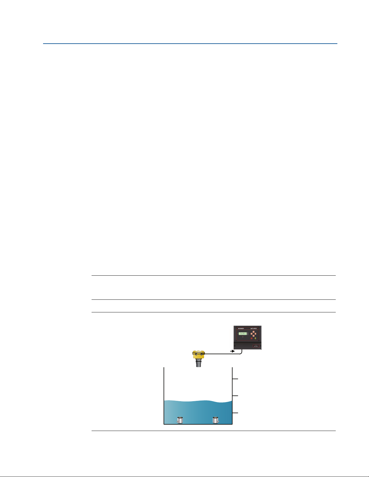
Section 4: Getting started
5.0 m (P411)
8.0 m (P421)
2.0 m (P412 and P422)
Level in m
Pump 1
Pump 2
June 2014
Duty Assist relay with common off points
This function requires two or more Assist mode relays. Two or more of these relays can be
energized at the same time (assisting), and they all de-energize at a common off point.
An Assist relay uses its On Point and Off Point parameters in a similar way to a Set Point mode
relay. A typical application would be emptying a wet well / lift station.
The worked example here illustrates how the function works. To keep the example simple, the
auto-sequencing options are not considered.
Example wet well / lift station application (emptying operation due to rising level)
using assist mode relays and common off points
Consider an application with two relay outputs, RL1 and RL2, connected to individual pumps in a
wet well/lift station. The control unit PV value (D800) is a level measurement in metres (m).
In Figure 4-28, both Pump 1 and Pump 2 are off because the liquid level is at a
When the level rises above 5 m (On point, P411), the relay RL1 is energized to start
If the level continues to rise and is above 8 m (On point, P421), relay RL2 is energized to
Reference Manual
IP2030/RM, Rev AA
satisfactory level, below 5 m
Pump 1 (Figure 4-29)
start Pump 2 and assist Pump 1. Relay RL1 stays energized to keep Pump 1 pumping
(Figure 4-30)
Pump 1 and Pump 2 continue to pump down until the level falls to below 2 m (Off Point,
P412 and P422), at which relays RL1 and RL2 de-energize to switch off both pumps
(Figure 4-31).
In this emptying application, the common off point is P412 (Off point, relay RL1) and
P422 (Off point, relay RL2), both of which are at the 2 m level.
Note
If Pump 1 had kept the level below 8 m, it would stay switched on until the level is 2 m.
Safeguards to prevent over-use of a pump are in “Relay safeguard options” on page 71.
Figure 4-28. Both Pump 1 and Pump 2 are off (the level is okay)
Section 4: Getting started74
Page 83

Reference Manual
5.0 m (P411)
8.0 m (P421)
2.0 m (P412)
Level in m
Pump 1
Pump 2
5.0 m (P411)
8.0 m (P421)
2.0 m (P412)
Level in m
Pump 1
Pump 2
5.0 m (P411)
8.0 m (P421)
2.0 m (P412)
Level in m
Pump 1
Pump 2
IP2030/RM, Rev AA
Section 4: Getting started
June 2014
Figure 4-29. Pump 1 is on (the rising level is above 5 m)
Figure 4-30. Pump 1 and Pump 2 are on (the rising level is above 8 m)
Section 4: Getting started
Figure 4-31. Pump 1 and Pump 2 are off (the falling level is below 2 m)
75
Page 84
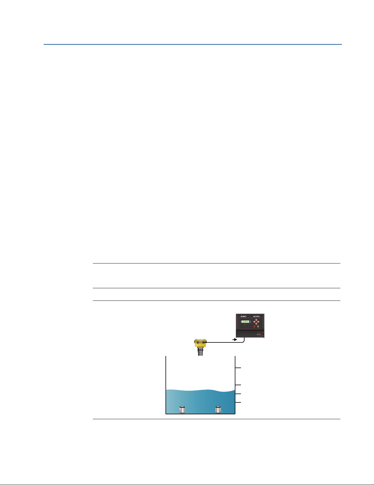
Section 4: Getting started
5.0 m (P411)
8.0 m (P421)
3.5 m (P422)
2.0 m (P412)
Level in m
Pump 1
Pump 2
June 2014
Duty Assist with split off points
This function requires two or more Assist mode relays. Two or more of these relays can be
energized at the same time (assisting), and they all de-energize at a split off points.
An Assist relay uses its On Point and Off Point parameters in a similar way to a Set Point mode
relay. A typical application would be emptying a wet well / lift station.
The worked example here illustrates how the function works. To keep the example simple, the
auto-sequencing options are not considered.
Example wet well / lift station application (emptying operation due to rising level)
using assist mode relays and split (separate) off points
Consider an application with two relays, RL1 and RL2, connected to individual pumps in a
wet well. The control unit PV value (D800) is a liquid level measurement in metres.
In Figure 4-32, both Pump 1 and Pump 2 are off because the liquid level is at a
When the level exceeds 5 m (On Point, P411), relay RL1 is energized to start Pump 1
When the level exceeds 8 m (On Point, P421), relay RL2 is energized to start Pump 2 and
Reference Manual
IP2030/RM, Rev AA
satisfactory level, below 5 m
(Figure 4-33)
assist Pump 1. Relay RL1 stays energized to keep Pump 1 pumping (Figure 4-34)
When the level falls to below 3.5 m (Off point, P422), relay RL2 de-energizes to switch
off Pump 2 (Figure 4-35)
When the level falls to below 2 m (Off point, P412), relay RL1 de-energizes to switch
off Pump 1
Note
If Pump 1 keeps the level below 8 m, it would stay switched on until the level is 2 m.
Safeguards to prevent overuse of pumps are in “Relay safeguard options” on page 71
Figure 4-32. Both Pump 1 and Pump 2 are off (the level is okay)
Section 4: Getting started76
Page 85

Reference Manual
5.0 m (P411)
8.0 m (P421)
3.5 m (P422)
2.0 m (P412)
Level in m
Pump 1
Pump 2
5.0 m (P411)
8.0 m (P421)
3.5 m (P422)
2.0 m (P412)
Level in m
Pump 1
Pump 2
5.0 m (P411)
8.0 m (P421)
3.5 m (P422)
2.0 m (P412)
Level in m
Pump 1
Pump 2
IP2030/RM, Rev AA
Section 4: Getting started
June 2014
Figure 4-33. Pump 1 is on (the rising level is above 5 m)
Figure 4-34. Both Pump 1 and Pump 2 are on (the rising level is above 8 m)
Section 4: Getting started
Figure 4-35. Pump 1 on and Pump 2 is off (the falling level is below 3.5 m)
77
Page 86
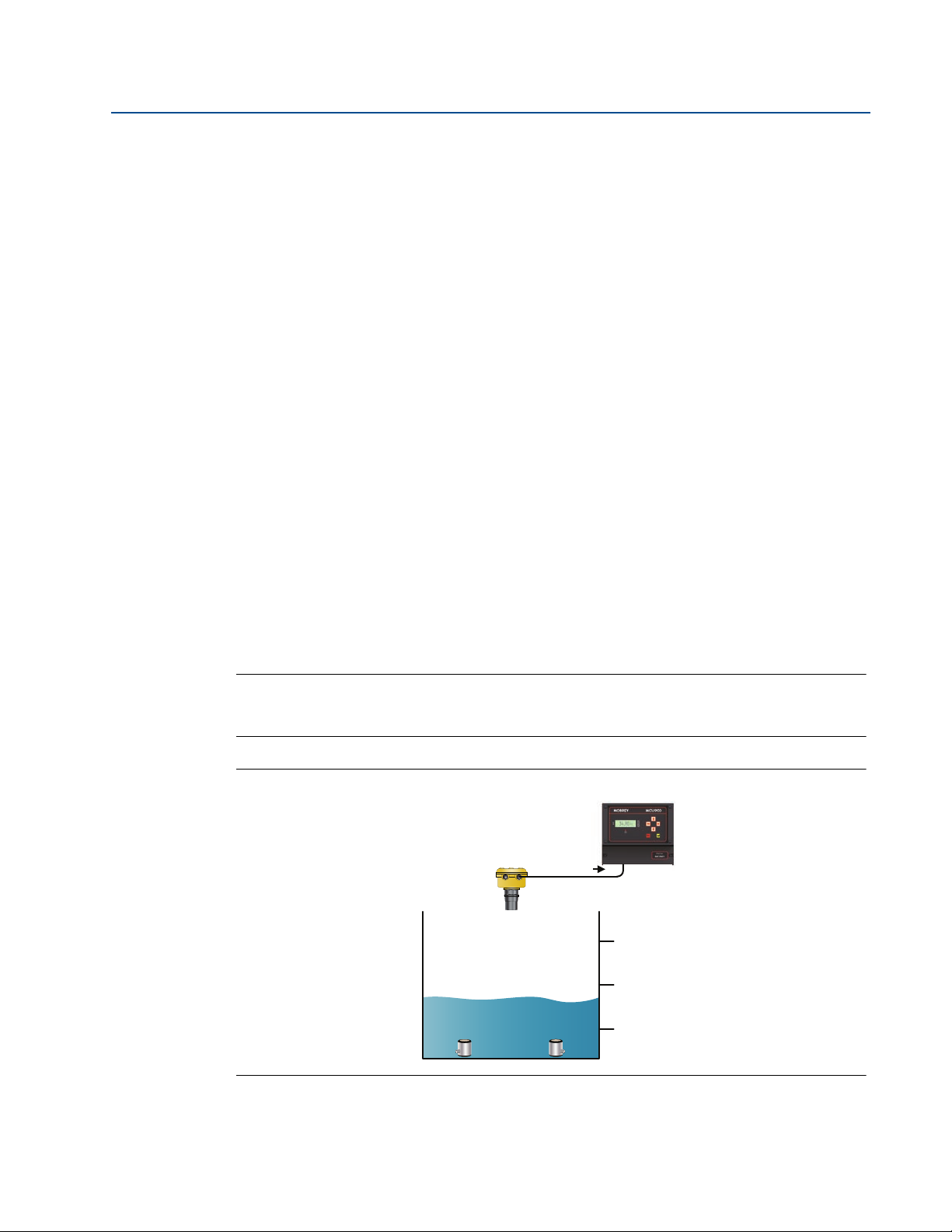
Section 4: Getting started
5.0 m (P411)
8.0 m (P421)
2.0 m (P412 and P422)
Level in m
Pump 1
Pump 2
June 2014
Standby, Common Off mode relay
This function requires two or more Standby, Common Off mode relays. Only one of these
relays is energized at any one time and the others are on standby to take over when needed.
A Standby, Common Off relay uses its On Point and Off Point parameters in a similar way to a
Set Point mode relay. A typical application would be emptying a wet well / lift station.
The worked example here illustrates how the function works. To keep the example simple, the
auto-sequencing options are not considered.
Example wet well application (emptying operation due to rising level) using standby,
common off point relays
Consider an application with two relay outputs, RL1 and RL2, connected to individual pumps in a
wet well. The control unit PV value (D800) is a liquid level measurement in metres (m).
In Figure 4-36, both Pump 1 and Pump 2 are off because the liquid level is at a
When the level rises above 5 m (On point, P411), the relay RL1 is energized to start
If the level continues to rise and is above 8 m (On point, P421), the relay RL2 is
Reference Manual
IP2030/RM, Rev AA
satisfactory level, below 5 m
Pump 1 (Figure 4-37)
energized to start Pump 2. Relay RL1 is de-energized to switch off Pump 1 (Figure 4-38)
Pump 2 continues to pump until the level falls below 2 m (Off Point, P412), at which
relay RL2 will de-energize to switch off Pump 2. (Pump 1 is already switched off).
In this emptying application, the common off point is P412 (Off point, relay RL1) and
P422 (Off point, relay RL2), both of which are at the 2 m level.
Note
If Pump 1 had kept the level below 8 m, it would stay switched on until the level is 2 m.
Safeguards to prevent over-use of a pump are in “Relay safeguard options” on page 71.
Figure 4-36. Both Pump 1 and Pump 2 are off (the level is okay)
Section 4: Getting started78
Page 87
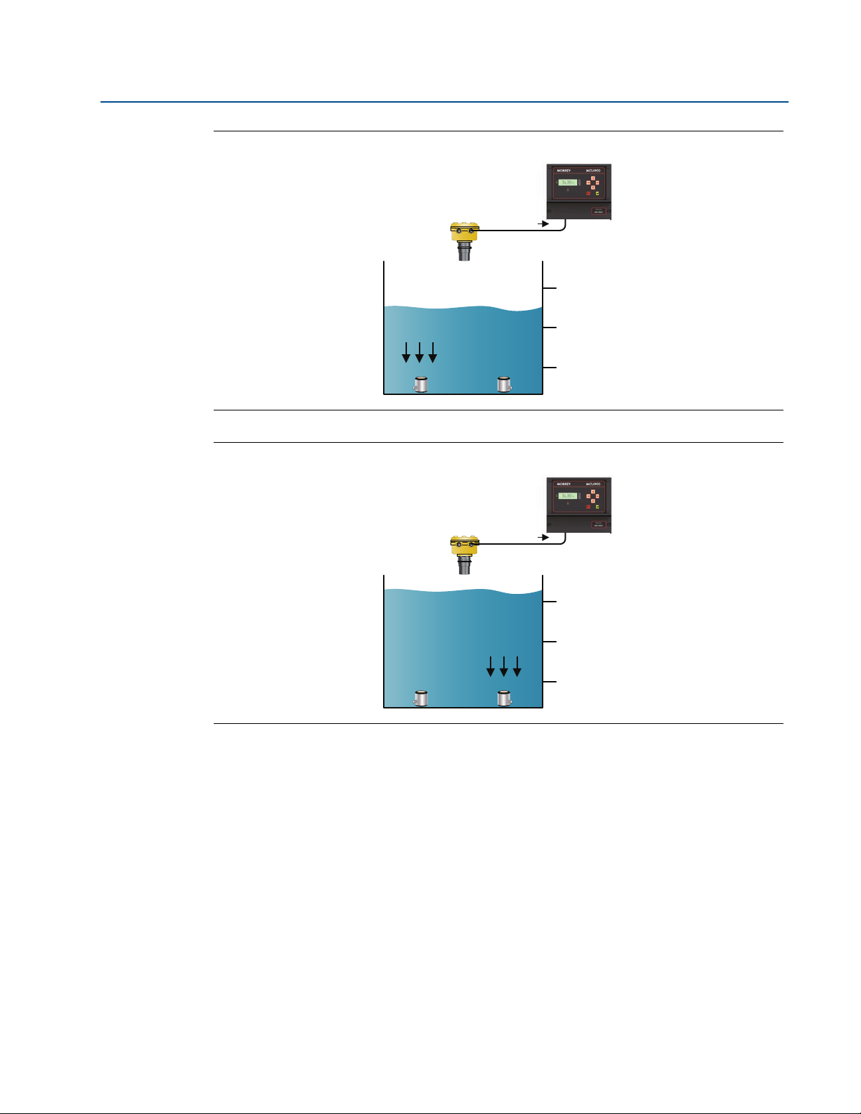
Reference Manual
5.0 m (P411)
8.0 m (P421)
2.0 m (P412)
Level in m
Pump 1
Pump 2
5.0 m (P411)
8.0 m (P421)
2.0 m (P412)
Level in m
Pump 1
Pump 2
IP2030/RM, Rev AA
Section 4: Getting started
June 2014
Figure 4-37. Pump 1 is on (the rising level is above 5 m)
Figure 4-38. Pump 1 is off and Pump 2 is on (the rising level is above 8 m)
Section 4: Getting started
79
Page 88

Section 4: Getting started
5.0 m (P411)
8.0 m (P421)
2.0 m (P412)
Level in m
Pump 1
Pump 2
June 2014
Standby, Split Off mode relay
This function requires two or more Standby, Split Off Point mode relays. Only one of these
relays is energized at any one time and the others are on standby to take over when needed.
A Standby, Split Off Point relay uses its On Point and Off Point parameters, just like a Set Point
mode relay. A typical application would be emptying a wet well / lift station.
The worked example here illustrates how the function works. To keep the example simple, the
auto-sequencing options are not considered.
Example wet well / lift station application (emptying operation due to rising level)
using standby, split off point relays
Consider an application with two relays, RL1 and RL2, connected to individual pumps in a
wet well. The control unit PV value (D800) is a liquid level measurement in metres.
In Figure 4-39, both Pump 1 and Pump 2 are off because the liquid level is at a
When the level exceeds 5 m (On Point, P411), relay RL1 is energized to start Pump 1.
When the level exceeds 8 m (On Point, P421), relay RL2 is energized to start Pump 2.
Reference Manual
IP2030/RM, Rev AA
satisfactory level, below 5 m
(Figure 4-40)
Relay RL1 is de-energized to switch off Pump 1 (Figure 4-41)
When the level falls to below 5 m (Off point, P422), relay RL2 de-energizes to switch off
Pump 2. Relay RL1 is energized to switch on Pump 1 (Figure 4-42)
In this emptying application, the switch off point for Pump 2 is 5 m; the On Point for
relay 1 P411 (On point, relay RL1) is used. P422 (Off point, relay RL2) is ignored.
When the level falls below 2 m (Off point, P412), relay RL1 de-energizes to switch off
Pump 1
Note
If Pump 1 keeps the level below 8 m, it would stay switched on until the level is 2 m.
Safeguards to prevent overuse of pumps are in “Relay safeguard options” on page 71
Figure 4-39. Both Pump 1 and Pump 2 are off (the level is okay)
Section 4: Getting started80
Page 89
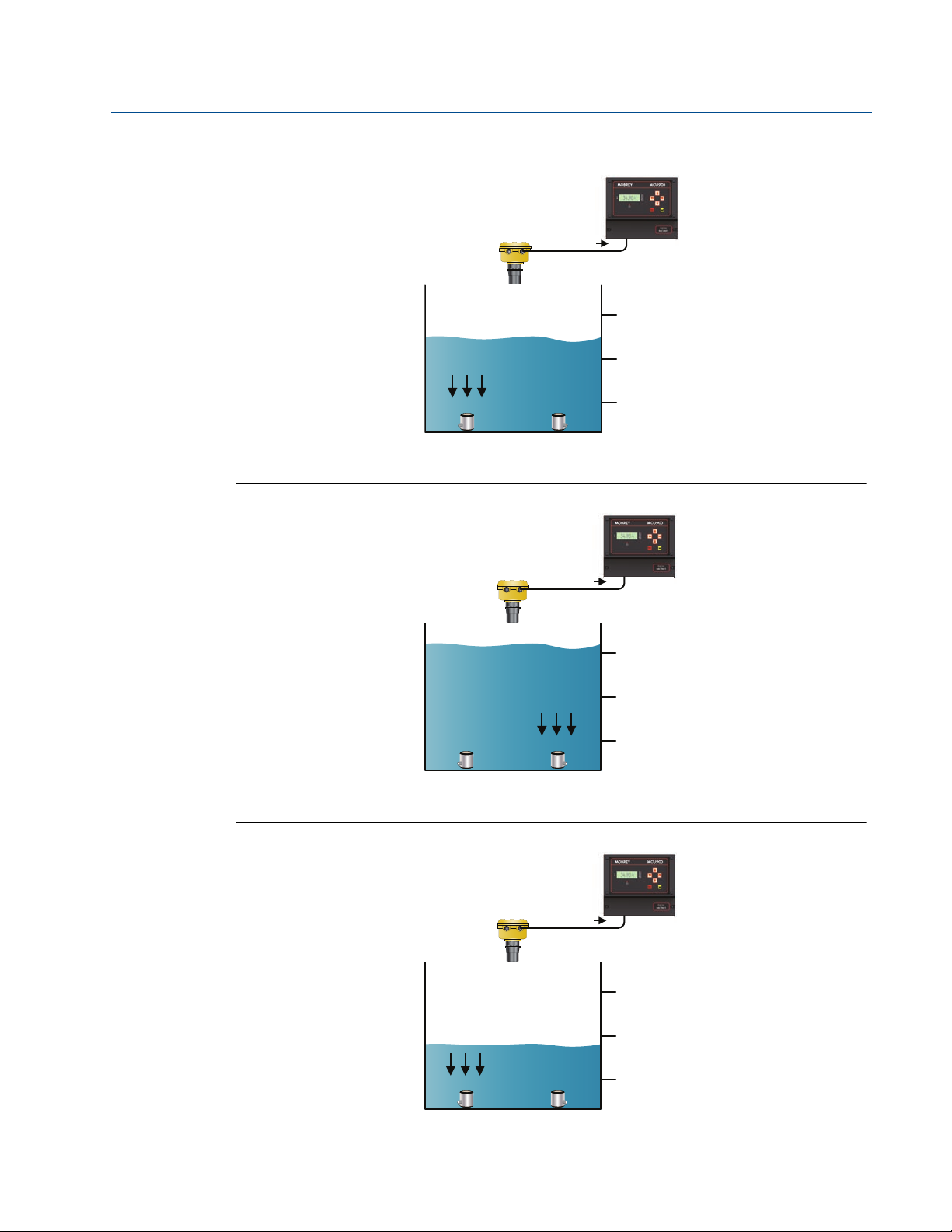
Reference Manual
5.0 m (P411)
8.0 m (P421)
2.0 m (P412)
Level in m
Pump 1
Pump 2
5.0 m (P411)
8.0 m (P421)
2.0 m (P412)
Level in m
Pump 1
Pump 2
5.0 m (P411)
8.0 m (P421)
2.0 m (P412)
Level in m
Pump 1
Pump 2
IP2030/RM, Rev AA
Section 4: Getting started
June 2014
Figure 4-40. Pump 1 is on (the rising level is above 5 m)
Figure 4-41. Pump 1 is off and Pump 2 is on (the rising level is above 8 m)
Section 4: Getting started
Figure 4-42. Pump 1 is on and Pump 2 is off (the falling level is below 5 m)
81
Page 90

Section 4: Getting started
June 2014
Totalizer mode relay
Menu: SETUP / [CONTROLLER /] OUTPUT / TOTALIZER
A Totalizer relay can output a pulse for each time that the internal totalizer count (D828)
increments. The duration of the pulse may set using parameter P534.
P534 Pulse Width (Factory default is 100)
The duration controls both the 'On' time and the 'Off' time - i.e. the pulse width - and
Note
If the totalizer count is running faster than the relay can produce pulses, an internal
Sampler mode relay
Sampler relays output pulses at a slower rate than a Totalizer relay. The Sampler relay can be
used as a coarse totalizer or as a trigger to an external event.
Reference Manual
IP2030/RM, Rev AA
may be set to a value between 10 ms and 2.5 seconds in steps of 10ms.
accumulator stores the excess pulses. The stored excess pulses are output by the
Totalizer relay after the totalizer count rate reduces.
Menu: SETUP / [CONTROLLER /] OUTPUT / TOTALIZER
P535 Sampler Factor (Factory default is 0)
This is for defining the frequency of the Sampler pulse. For example, a value of 100
means that the Sampler relay outputs a single pulse for every 100
th
increment to the
Tot a lizer C ount (D828/D829)
The pulse width is the same as selected for the Totalizer relay (P534)
Note
For information on setting up the totalizer, see page 95 onwards.
Fault mode relay
Fault relays de-energize when a particular fault condition exists. Parameter D831 shows a list of
active faults. Table 4-8 on page 94 has a summary of reporting methods for faults.
Menu: SETUP / [CONTROLLER /] OUTPUT / FAULT
P560 System Fault (Factory default is Both)
Fault relay de-energizes while there is a control unit fault and the option is Both or Relay
P561 CU Temp Fault (Factor y default setting is None)
Fault relay de-energizes while the CPU temperature rises above 65C and the option is
Both or Relay. Read-only parameter D844 shows the live temperature reading
P562 Xmtr Fault (Factory default setting is None)
Fault relay de-energizes while a HART transmitter signals a fault and the option is
Both or Relay
Section 4: Getting started82
Page 91

Reference Manual
IP2030/RM, Rev AA
Section 4: Getting started
June 2014
P563 Digital Input (Factory default setting is None)
Fault relay de-energizes while digital input IN1 or IN2 is triggered and the option is
Both or Relay
See “Digital inputs IN1 and IN2” on page 63 for how to select the Fault action required
for this feature
Note
Faults can be indicated using the output current if the Current or Both options are
selected (see “Set-up the current output” on page 68)
PV Limits mode relay
Menus:
SETUP / [CONTROLLER /] OUTPUT / RELAY / RELAY 1, / RELAY 2, etc.
This relay mode uses the relay On Point and Off Points (e.g. P411 and P412) as high and low
limit alarms for the control unit PV value (D800). The points can be in any order of value.
The relay is energized while the PV value exceeds the higher limit point value or while it is below
the lower limit point value.
Rate of Change mode relay
Menus:
SETUP / [CONTROLLER /] OUTPUT / RELAY / RELAY 1, / RELAY 2, etc. and
MONITOR / [CONTROLLER /] READINGS / Rate of Change
A rate of change value for the control unit PV value (D800) is calculated every 5 seconds in units
of PV per minute:
D809 = (PV
now
- PV
5 seconds ago
The On and Off points of a Rate of Change (RoC) mode relay are used as high and low limits for
read-only parameter D809. Limit values are in units of PV per minute (PV/min) and can be in any
order of value. The relay is energized while D809 exceeds the higher limit value or falls below the
lower limit value.
Typically, where the PV value is a liquid level measurement, the RoC relay can be used to warn of
a quickly rising or falling liquid level. Alternatively, the RoC mode relay can be used for
controlling the rate of liquid flow.
For further uses of D809, see “Pump Efficiency alarm (Mobrey MCU901 and MCU902 only)” on
page 89 and “Pumped volume totalizing” on page 90.
) * 12
Section 4: Getting started
83
Page 92

Section 4: Getting started
June 2014
Pump On Delay
Menu: SETUP / [CONTROLLER /] OUTPUT / RELAY / OVERRIDES
P499 Pump On Delay (Factory default is “3 s”)
This function is to prevent pumps from all being switched on simultaneously, which
When multiple relays are used for pump control (or as a set point) and power is lost,
Auto-sequence (Mobrey MCU901 and MCU902 only)
(Special Control Function – see Table 4-5 on page 73 for a full list)
Optional automatic rotation of the leading (most used) relay can be applied to Assist or Standby
mode relays. To use these options, two or more relays must have the same mode. The lowest
numbered relay is initially the lead relay.
Reference Manual
IP2030/RM, Rev AA
could cause a massive surge
this function provides a delay of 0 up to 9 seconds (3 seconds by default) for the
second, third, fourth, and fifth relay when power is re-established
Note
The rotation of relays is performed without the actual swapping of values between
relay parameters.
P270 Auto Seq Enable (Factory default is “Off”)
Select a rotation auto-sequence. All options are summarized in Tab l e 4 - 6
P271 Auto Seq Qual (Factory default is 0)
This defines the threshold (e.g. how many starts) before applying an auto-sequence to
rotate the 'lead' to the next relay with the same mode
Table 4-6. Auto-sequence options
Option Rotation basis
Standby Star ts For Standby mode relays only - rotation is based on how many times the 'leading' relay has
been energized compared to parameter P271.
Stdby On Time For Standby mode relays only - rotation is based on the hours that the 'leading' relay has been
energized compared to parameter P271.
Stdby Ratio T
Stdby Ratio S
Assist Starts Rotation of 'leading' Assist mode relay is based on how many times it has been energized
Assist On Time Rotation of 'leading' Assist mode relay is based on the hours that it has been energized
Assist Ratio T
Assist Ratio S
Off No rotation required.
(1) Ratio is based on the first two lowest-numbered relays with the same mode.
(1)
For two Standby mode relays only - rotation is based on the ratio of ON time for two relays
compared to P271.
(1)
For two Standby mode relays only - rotation based on the ratio of starts (times energized)
compared to P271.
compared to P271.
compared to P271.
(1)
For two Assist mode relays only - rotation based on the ratio of ON time for the two relays
compared to P271.
(1)
For two Assist mode relays only - rotation based on the ratio of starts (times energized)
compared to P271.
Section 4: Getting started84
Page 93

Reference Manual
IP2030/RM, Rev AA
Section 4: Getting started
June 2014
Energy saving
(Special Control Function – see Table 4-5 on page 73)
Menu: SETUP / [CONTROLLER /] OUTPUT / RELAY / OVERRIDES
P275 Engy Save Strt (Factory default is 0:00 h:m)
Set the time of day at which selected relays (P276) will energize until each relay Off
Point is reached. The energy saving start time is valid for one minute; if missed by the
MCU900 Series control unit being in Program mode, no action is taken when
subsequently put into Run App mode.
P276 Engy Save RL (Factory default is 00000)
Select relays for the operation associated with parameter P275
Each digit represents a relay. Relay RL1 is selected by editing the first digit to be a “1”.
Similarly, relay RL5 is selected with the fifth digit. To de-select a relay, change the
appropriate digit back to a “0”
Scum line prevention (Mobrey MCU901 and MCU902 only)
(Special Control Function – see Table 4-5 on page 73 for a full list of auxiliary relay functions)
This special control function is normally used with a pump control application to provide a small
variance in the start and stop level for the pump. It will help to prevent a build-up of scum on the
side of a wet well or sump.
Menu: SETUP / [CONTROLLER /] OUTPUT / RELAY / OVERRIDES
P277 Scum line var (Factory default is 0.0)
This parameter defines a maximum variance in the On Points and Off Points of selected
relays (P278). The variance is entered in the units of the On/Off Point, spaced in ten
equal increments within the On Point and Off Point limits. Each time the selected relays
(P278) de-energize, the variance moves on an increment
P278 Scum line RL (Factory default is 00000)
Select relays for the operation associated with parameter P277
Each digit represents a relay. Relay RL1 is selected by editing the first digit to be a “1”.
Similarly, relay RL5 is selected with the fifth digit. To de-select a relay, change the
appropriate digit back to a “0”
Pump-down (Mobrey MCU901 and MCU902 only)
(Special Control Function – see Table 4-5 on page 73 for a full list)
Section 4: Getting started
In a pump-down application, the lowest relay Off Point ('pump off' level) is normally a fixed level
above the Transmitter Bottom Reference point. However, it is sometimes required to make the
pumps continue to run for a period past the Off Point or run down the level to the Transmitter
Bottom Reference point. This can clear a sump of sludge that may have collected at the bottom.
Pump-down can be initiated automatically at pre-set intervals. A digital input can also initiate
pump-down at any time and this will re-set the interval before the next pump-down.
85
Page 94

Section 4: Getting started
June 2014
Pump-down automatically stops when the control unit PV (D800) is zero or after 20 minutes if a
duration (P274) has not been programmed, whichever is the shorter period.
Note
For details on configuring a digital input to initiate a pump-down operation,
Menu: SETUP / [CONTROLLER /] OUTPUT / RELAY / OVERRIDES
The relay mode must be Set point, Assist or, Standby, and parameters P272 to P274 edited to
set-up the pump down operation.
P272 Pump down RL (Factory default is 00000)
This is for selecting relays for a pump-down operation
Each of the five digits represents a relay. Relay RL1 is selected by editing the first digit to
P273 Pump down Int (Factory default is 000:00 h:m)
Reference Manual
IP2030/RM, Rev AA
see “Digital inputs IN1 and IN2” on page 63
a “1”. Similarly, relay RL5 is selected by editing the fifth digit. To de-allocated, edit the
appropriate digit back to a “0”
This defines a fixed interval (hours and minutes) between pump-downs
P274 Pump down Dur (Default setting is 00:00)
This defines the period (hours and minutes) that the relay will remain energized for the
pump-down. Safeguards may extend or reduce this period (see “Relay safeguard
options” on page 71)
D845 Next pump-down h:m (Factory default is 000:00)
This shows the time remaining before the next pump-down is started. The display
shows 000:00 if a pump-down is in progress or if it is not set-up
Custom mode relay
(Special Control Function – see Table 4-5 on page 73 for a full list)
A custom mode relay is typically used together with a secondary external device to provide a
voltage-free contact connected to one of the controller digital inputs (IN1 or IN2).
For example, this function may be used to provide a low flow cut-off for a pump control if the
pump is provided with a flow/no-flow switch. A second relay contact assigned to pump control
would then be wired in series with the Custom mode relay to provide the low flow cut-off.
Menu: SETUP / [CONTROLLER /] APPLICATION / CUSTOM
P250 Start On (Factory default is “None”)
Relay energizes when the selected condition is true. See also Table 4-7 on page 87
P251 Stop On (Factory default is “None”)
Relay de-energizes when the selected condition is true. See also Table 4-7 on page 87
Section 4: Getting started86
Page 95

Reference Manual
IP2030/RM, Rev AA
Section 4: Getting started
June 2014
P252 Stop If (Factory default is “None”)
Relay de-energizes when the selected condition is true. See also Table 4-7 on page 87.
P252 is a fail-safe for P251
P253 Start Time (Factory default is “7:00” - i.e. 7AM)
This defines the clock time for when a Custom mode relay operation will begin
(if P250 = Time) or end (if P251 = Time)
P254 Interval (Factory default is “1:00” i.e. 1hr 0min)
This is for defining the interval for repeating a Custom mode relay operation. P255 and
P256 are for setting up a second starting time and an associated interval
P257 Max Retries (Factory default is 10)
This defines the maximum number of failed attempts to perform Custom mode relay
operations before it is deemed an alarm condition.
The alarm condition can happen if the control unit is in Program mode, which prevents
all Custom mode relay operations from starting. Also, it can happen when the
maximum time for an energized relay (relay safeguard, page 71) has been reached and
is preventing a Custom mode relay operation from completing. For alarm indication
options, see “Set-up alarms” on page 91
Table 4-7. P250/P251/P252 options
Start on
Options Purpose of option
None Switched off. Yes Ye s Ye s
Time P253 and P254 determine when a Custom mode relay is to
be energized.
PV > Level Energize a Custom mode relay when the control unit PV
value (D800) is greater than the relay On Point.
PV < Level De-energize a Custom mode relay when the control unit PV
(1)(2)
Ext Trig
Ext Trig Xs
(1) This does not require Digital Input IN1 or IN2 to be allocated an ac tion
(2) Abbreviations: "Ext Trig" = External Trigger (Digital Input)
value (D800) less than the relay On point.
Energize a Custom mode relay when a digital input is
active.
(1)(2)
When a Digital Input is active, de-energize a Custom mode
relay after X seconds delay.
(P250)
Yes Ye s -
Yes - -
- Yes Ye s
Yes Ye s Ye s
- - Yes
Stop on
(P251)
Stop if
(P252)
Note
For any of the alarms below to be indicated by a relay or current output, an indication
method must be selected. See “Alarm indication selection” on page 91 for details
Section 4: Getting started
87
Page 96

Section 4: Getting started
June 2014
Relay Operations alarm
(Special alarm – see Table 4-5 on page 73 for a full list of auxiliary relay functions)
Menu: SETUP / [CONTROLLER /] APPLICATION / ALARM
P491 RL operations (Factory default is 0)
It is an alarm condition when the number of operations done by a selected relay (P492)
Relay operation counters parameters D811 to D815 are in the MONITOR menu.
For alarm indication options, see “Set-up alarms” on page 91
P492 RL ops rly sel (Factory default is "Disabled")
Select the relay for the monitoring operation associated with parameter P491
Relay Run-time alarm
Reference Manual
IP2030/RM, Rev AA
is higher than the number in P491
See also “Health checking the MCU900 Series control unit” on page 110
(Special alarm – see Table 4-5 on page 73 for a full list of auxiliary relay functions)
Menu: SETUP / [CONTROLLER /] APPLICATION / ALARM
P493 RL runtime (Factory default is 0:00 h:m = OFF)
It is an alarm condition when a relay, selected by P494, has been energized for longer
than the period (hours and minutes) set by P493
Run-time counters parameters D821 to D825 are in the MONITOR menu.
See also “Health checking the MCU900 Series control unit” on page 110
For alarm indication options, see “Set-up alarms” on page 91
P494 RL run rly sel (Factory default is "Disabled")
Select the relay for the monitoring operation associated with parameter P493
Note
For any of the alarms below to be indicated by a relay or current output, an indication
method must be selected. See “Alarm indication selection” on page 91 for details
No Activity alarm
(Special alarm - see Table 4-5 on page 73 for a full list of auxiliary relay functions)
Menu: SETUP / [CONTROLLER /] APPLICATION / ALARM
P497 No Activity Del (Factory default is 0:00 h:m)
It is an alarm condition if there is no relay activity for the period (hours and minutes)
defined by parameter P497. Relays are selected for monitoring using parameter P498.
The alarm condition is cleared when any of the monitored relays are energized
For alarm indication options, see “Set-up alarms” on page 91
Section 4: Getting started88
Page 97

Reference Manual
IP2030/RM, Rev AA
Section 4: Getting started
June 2014
P498 No Activity RL (Factory default is 00000)
Select relays for the relay inactivity monitoring operation
Each digit represents a relay. Relay RL1 is selected for monitoring by editing the first
digit to be a “1”. Similarly, relay RL5 is selected with the fifth digit. To de-select a relay,
change the appropriate digit back to a “0”
Rising Level alarm
(Special alarm – see Table 4-5 on page 73 for a full list of auxiliary relay functions)
Menu: SETUP / [CONTROLLER /] APPLICATION / ALARM
P490 R Lev alrm del (Factory default is 0:00 m:s)
The Rising Level alarm requires a minimum of one Assist or Standby mode relay.
If any Standby relay is energized, monitoring of the rising level is activated. For Assist
relays, they must all be energized for monitoring of the rising level to be activated.
A timed delay (P490) starts after the monitoring is activated. If the level is still rising
after the delay time has expired and the calculated rate of change of the control unit PV
(D800) is positive, the result is a Rising Level alarm condition. The alarm condition stops
as soon as the rate of change is negative, indicating a falling level.
For the Rising Level alarm to be indicated by a relay output or the current output, a
method must be selected. See “Set-up alarms” on page 91
See also “Rate of Change mode relay” on page 83
Pump Efficiency alarm (Mobrey MCU901 and MCU902 only)
(Special alarm – see Table 4-5 on page 73 for a full list of auxiliary relay functions)
The pump efficiency feature allows an alarm to be indicated (P550, P4*1) if the calculated
pump efficiency falls below a defined limit (P495).
Menu: SETUP / [CONTROLLER /] APPLICATION / ALARM
P495 Pump effy limit (Factory default is 0% = OFF)
It is an alarm condition while the calculated pump efficiency is below the limit defined
by P495. The pump efficiency calculation is based on the rate of change of the control
unit PV (D800) and is independently monitored for each selected relay (P496)
Pump efficiency values for relays are saved in D861 to D864, located in the MONITOR
menu. See also “Health checking the MCU900 Series control unit” on page 110.
P496 Pump effy RL (Factory default is 0000)
Select relays for pump efficiency limit monitoring operation
Each digit represents a relay. Relay RL1 is selected by editing the first digit to be a “1”.
Similarly, relay RL4 is selected with the fourth digit. (Relay RL5 does not support this
feature.) To de-select a relay, change the appropriate digit to a “0”
Section 4: Getting started
Pump efficiency (PE) is calculated using the rate of change (RoC) of the control unit PV while a
relay is energized. The PE value is saved in D86*; the “*” is the number of the relay (1 to 4)
89
Page 98

Section 4: Getting started
June 2014
The calculation assumes that liquid continues to enter the well or tank at the rate just prior to
the relay energizing (pump starting).
The control unit continuously calculates the rate of change, sampling a new control unit PV
every 5 seconds (as described in Section “Rate of Change mode relay” on page 83).
Over the next 9 pump starts, a further 9 change of RoC values are stored such that the control
unit can then calculate an average value in change of RoC. This average value, “RoC100” is then
taken as being equivalent to the pump operating at 100% efficiency. A value of 100% is then
stored in D86*.
Each subsequent pump start, and change in RoC thereafter, is used in a rolling average
calculation for a new average value in change of RoC, RoCnew, which is then compared to the
previous value “RoC100” and a new PE percentage value calculated using:
PE % = (RoCnew / RoC100) * 100
If the resulting PE is greater than 100%, the RoC100 is updated to the new value and the PE is
re-stated as 100% based on this new value.
If the resulting PE is less than 100%, then the PE is calculated as above and stored in D86*
Reference Manual
IP2030/RM, Rev AA
If the PE is below the limit set (P495), the PE alarm condition is true. To indicate an alarm by
Relay or Current Output, a method must be selected (see “Set-up alarms” on page 91).
Note
The alarm condition is automatically cleared if the calculated PE rises above the limit
(P495) by 5% or more
Pumped volume totalizing
(Totalizer Option – see Table 4-5 on page 73 for a full list of auxiliary relay functions)
This function is for calculating the total throughput in a contents volume application.
The control unit monitors the change in volume when no pumps are running i.e. when any
Assist or Standby mode relay is de-energized. It calculates the rate of change (RoC) of the
control unit PV (D800) every five seconds and then converts it to a rate of change per minute for
displaying as parameter D809.
When a pump is turned on, the control unit assumes that the rate of inflow remains the same as
it was just before starting the pumps. The RoC value (D809) is frozen while the pumps are on i.e.
when any Assist or Standby mode relay is energized.
To totalize pumped volume, the control unit PV (D800) must be in volume units so that the RoC
value (D809) is in units of volume per minute. The control unit integrates this volume every
second and increments the totalizer for every integer unit.
3
If the RoC value (D809) is 12 m
3
1.0 (m
), the Totalizer count (D828) increments every five seconds (1/12th of a minute).
per minute and the Total factor parameter (P530) is set to
Note
The Totalizer Wizard can be used to set-up pumped volume totalizing.
Section 4: Getting started90
Page 99

Reference Manual
IP2030/RM, Rev AA
Menu: SETUP / [CONTROLLER /] OUTPUT / TOTALIZER
P530 Total factor (Factor default is 0.0)
One count is added to the Totalizer count (D828) for a quantity defined by P530
P531 Total units (Factory default is "None")
Pumped volume totalizing is enabled by the totalizer units (P531) being set to PVol.
(This parameter also defines the display units for parameter D828).
Note
For other associated parameters, see “Set-up totalizing on the Mobrey MCU901 control
unit” on page 95.
4.5.22 Set-up alarms
Alarms
The MCU900 Series control unit can detect the following alarm conditions:
Section 4: Getting started
June 2014
Control unit Primary / Process Value (PV) is out-of-limits
Current Output saturated
(Standard:
Logging memory filling (Mobrey MCU90F)
Logging memory full (Mobrey MCU90F)
Digital input is configured to force an alarm when active
Maximum number of failed Custom relay operation attempts
Current Input saturated
Rising liquid level
Relay operation count limit exceeded
Relay run time limit exceeded
Low pump efficiency (on the MCU901 and MCU902 only)
Relay inactivity
3.9mA or 20.8mA, NAMUR NE43: 3.8mA or 20.5mA)
Parameter D830 shows a list of active alarms. Alarms are indicated using relay outputs and the
current output. Table 4-8 on page 94 has a summary of reporting methods for alarms.
Alarm indication selection
Menu: SETUP / [CONTROLLER /] OUTPUT / ALARM
Section 4: Getting started
For each alarm, there is a dedicated parameter in the ALARM menu for selecting the method of
indication for that alarm. Options for parameters P540 to P551 are:
None – if the alarm is to be indicated (default factory setting)
Both – alarm is indicated by an Alarm mode relay and output current
Current – alarm is indicated by the output current only
Relay – alarm is indicated by an Alarm mode relay only
91
Page 100

Section 4: Getting started
June 2014
For information on Alarm mode relays, see “Set-up the relays” on page 69.
Parameter P402 is used to decide how the output current indicates an alarm condition.
See “Set-up the current output” on page 68 for alarm action options.
P540 PV Over Limits (Factory default is "None")
Select the indication method for the alarm condition that happens while the control
P541 mA Out Sat (Factory default is "None")
Select the indication method for the alarm condition that happens while the
P542 Log mem filling (Factory default is "None")
Select the indication method for the alarm condition that happens while the available
P543 Digital Input (Factory default is “None”)
Select the indication method for the alarm condition that happens while a digital input,
See “Digital inputs IN1 and IN2” on page 63 for how to select the Alarm action required
Reference Manual
IP2030/RM, Rev AA
unit PV value is outside pre-set limits. See also “PV Limits mode relay” on page 83
output current is
3.8 mA or 20.5 mA
logging memory is low. See also “P593 Low Mem Alarm (Default is 0%)” on page 64
configured with an action to force this alarm, is energized.
for this feature
P544 Max retries (Factory default is “None”)
Select the indication method for the alarm condition that happens while a Custom relay
operation is unable to complete, even after a pre-set number of attempts (P257)
See also “Custom mode relay” on page 86 for information
P545 mA In Sat (Factory default is "None")
Select the indication method for the alarm condition that happens while the output
current is saturated i.e.
3.7 mA or 20.75 mA
P547 Rising Level (Factory default is "None")
Select the indication method for the Rising Level alarm condition
See “Rising Level alarm” on page 89 for information
P548 RL Operations (Factory default is "None")
Select the indication method for the alarm condition that happens while a relay
operation counter is higher than a pre-set limit
See “Relay Operations alarm” on page 88 for information
P549 RL runtime (Factory default is "None")
Select the indication method for the alarm condition that happens while a relay is
energized for longer than a pre-set period
See “Relay Run-time alarm” on page 88 for information
Section 4: Getting started92
 Loading...