

Page 1

Installation Leaflet
IP227, Rev. AA
July 07
MCU200 Installation, Operation &
Maintenance Instructions
WARNING:
If this equipment is used in a manner not specified by the
manufacturer, the protection provided may be impaired.
All installation and commissioning of this equipment must
be carried out by electrically competent persons
Mobrey ultrasonic liquid level control or sludge
blanket or interface detection systems using
control unit type MCU200
MCU200
Contents
1. Sensor installation
2. Control unit installation
3. Applications:
3.1Gain adjustment
3.2Liquid level alarm
3.3Pump control and latching arms
3.4Blanket or interface detection
4. Spare parts and fault finding
Each Mobrey ultrasonic control system requires a sensor to
suit the specific application, plus a control unit.
These installation instructions cover the Mobrey control units
in the MCU200 series.
Specification
Power supply MCU 201 110/120 ±10% 220/240±10% 50-60 Hz
Installation category MCU 201 II-IEC664 for 230V ac supply III-IEC664 for 115V ac supply
Pollution degree MCU 201 2-IEC664
Power consumption MCU 201 6VA approx at 240 Vac
Power supply MCU 203 24V dc (20V Min, 30V Max) Supply must be floating or negative earth
Current consumption MCU 203 0.1A Max
Relay output 5A at 230V ac DPCO
Relay state Normal state selectable energised/de-energised
Relay delay 0.5,2,8,30 seconds selectable. Operates for change of relay state in
one direction only. 50msecs in other direction. (Approx.)
LED indicators Red for alarm, Green for normal, Yellow for cable fault
LED state Green/Red indication selectable for either sensor state
Sensors compatible Any Mobrey ultrasonic gap, Hisens or Interface sensor
Sensor frequency Switch selects electronics operational at either l MHz or 3.7 MHz
Cable check Option selectable for certain sensors
External input Used to hold relay de-energised to provide pump control
Box size 200 x 120 x 75mm
Fixing centres 188 x 188
Box rating IP65 Polycarbonate (clear lid)
Temperature -40
Holes for glands 3 off 16mmØ
EMC Emissions: EN50081-1 Immunity: EN50082-1
Safety EN61010-1
o
C to 55oC ambient
www.mobrey.com
Page 2
1. Sensor Installation
1.1 General description
Each Mobrey ultrasonic sensor contains two piezoelectric
crystals. A high frequency signal (1 MHz or 3.7 MHz)
generated by the control unit is transmitted to one
piezoelectric crystal by coaxial cable. This crystal converts the
electrical signal into an ultrasonic oscillation.
The sensor design allows the ultrasonic oscillation to pass from
the transmitter crystal to the receiver piezoelectric crystal.
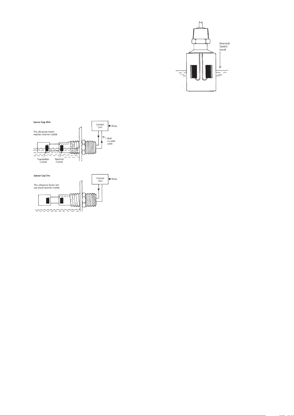
Most Mobrey sensors (300 or 400 series) are “gap” type
sensors, where the two piezoelectric crystals are separated by a
gap. When the gap is in liquid the signal reaches the receiver,
because of the low ultrasonic attenuation of the liquid. When
the gap is filled with air, no ultrasonic signal can pass from
transmitter to receiver.
See figure 1.
Fig.2. Hi-Sens transducer
The Hi-Sens sensor consists of two ultrasonic transducers
mounted on the inside of a cylinder. When the sensor is not
submerged in the liquid, the signal from one transducer
resonates round the cylinder like a bell ringing. If the liquid
rises up around the sensor, this ringing is damped and the
signal received by the second transducer is significantly
attenuated. The ringing or oscillation of the sensor is
detected by the control unit. Switching occurs when the
liquid is about half way up the cylinder of the Hi-Sens body.
NOTE: For satisfactory operations the Hi-Sens must not be
positioned in a vessel or tube less than 100mm internal
diameter.
Fig 1.
When the gap is filled with liquid, the piezoelectric receiver
crystal converts the ultrasonic wave into an electrical signal,
which is transmitted back to the control unit using a second
coaxial cable. Usually the two coaxial cables to the sensor are
in one overall sheath. The control unit circuitry is a feedback
amplifier, which oscillates when the sensor is wet, and is
quiescent for the sensor dry. The “oscillating” or “nonoscillating” sensor states dictate the output relay states of the
MCU200.
For sludge blanket or interface detection the sensor
“oscillates” in a clear liquid, and is “non-oscillating” in the
sludge or at the interface. The amplifier gain adjustment
determines the sludge density for the change between these
two states. See section 3.4.
For Mobrey Hisens sensors, (type numbers HL, HD etc) the
metal body of the sensor provides the ultrasonic coupling
between the piezoelectric crystals. This coupling is reduced
when the sensor is under a liquid, so that for Hisens sensors
“oscillating” state is dry, in air, and the “non oscillating” state
is wet, submerged in a liquid.
1.2 Switching levels and orientation
Mobrey gap sensors should normally be mounted with the gap
vertical, to avoid build up of solids on the sensor faces on
either side of the gap. In this condition the switching level
will be half way up the face: if the sensor is mounted from
the side of the tank this is normally on the centreline of the
cylindrical body.
Occasionally such sensors are mounted with the sensor faces
horizontal, either to avoid air bubbles passing through the gap
or for convenience of installation.
In this case the switching level will be at the sensor face at
the top of the gap.
1.3 Installation of sensor
The sensor must be handled with care - it is a measuring
instrument. Before installation, check that sensor, cable and
control unit have not been damaged in transit. Drill and tap a
hole with a suitable thread. It is advisable to use a boss or
similar on thin walls. The sensor has a tapered thread. Use
PTFE tape or similar to seal the thread. Mark the sensor
hexagon to identify the gap orientation of the sensor, if
appropriate. Take care not to damage the sensor cable during
tightening.
The cable should be laid on cable trays and separated from
any high voltage or mains cables. The normal cable
termination is a plastic gland (to fit the MCU200 control box
drilled hole) and crimped terminal pins to suit the MCU200
terminals.
1.4 Extension cables
Extension Cables up to 50 metres long can be fitted to most
Mobrey ultrasonic sensors in the factory to special order but a
better site arrangement is to have a separate extension cable.
When double coaxial cable needs to be extended, two sets of
coaxial plugs and sockets will be needed, one set for transmit
and one receive.Care must be taken that the connectors are
not earthed or shorted together in any way, to prevent crosstalk or pick-up. The coaxial connections must be made in a
waterproof junction box. Terminal blocks should not be used.
The extension cable needs to be of 50ohm characteristic
impedance. Suitable dual coaxial extension cables can be
purchased from KDG Mobrey (Part No. K178).
For extensions over 50 metres it is recommended two runs of
single coaxial low loss cable is used, with the transmit and
return cable runs separated by 0.15 metres to minimise crosstalk.
If several sensor cables are being run together then all the
transmit cables (those connected to E2) should be grouped
together and all receive cables (those connected to 1E)
grouped together maintaining the separation specified above.
Page 3
2. Control Unit Installation
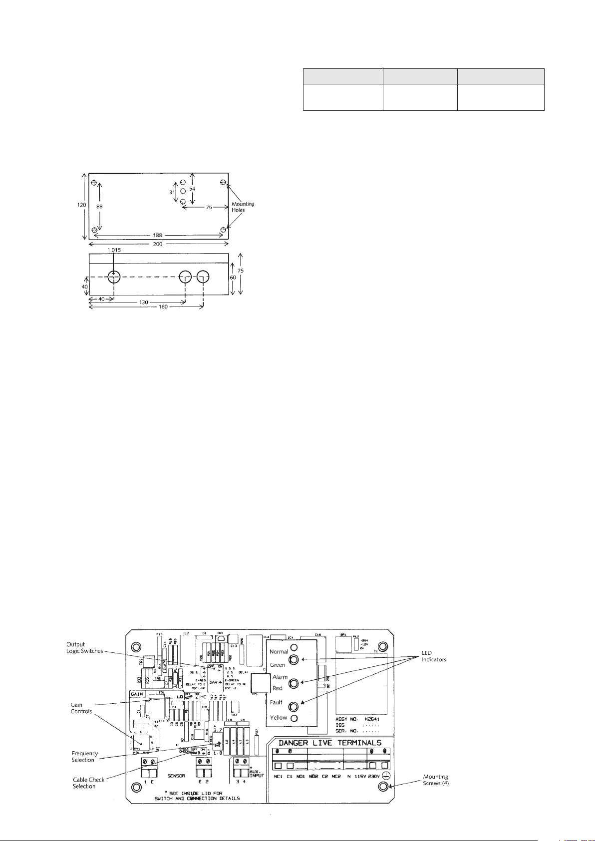
2.1 Mechanical
The control unit is supplied with three holes drilled in the
bottom (longer) side of the box. Two glands are supplied for
the power input cable and relay output cable. The sensor is
normally supplied fitted with a suitable gland on the cable.
Two further holes can be drilled in the bottom side of the box
should these be needed: it is recommended that the circuit
board is removed whilst drilling extra gland holes.
Fig. 4 MCU200 housing dimensions
All cable connections are made to the terminal blocks along
the bottom edge of the pcb (see fig.5). Release the terminal
screw before inserting the wire.
2.2 External Connections
Protection for permanently installed equipment
NOTE: This equipment is regarded as permanently installed
equipment and must be wired up using suitable cable for the
current and voltage specified. A suitable switch or circuit
breaker must be included in the installation and this should be
in close proximity to the equipment and marked as its
disconnecting device. A suitable fuse rated at 3A must be fitted
in the supply. Each relay circuit must be protected by a fuse not
exceeding the maximum rated current for the relay as specified
in the manual.
Fig 3 Suitable extension cables
50mtr 50-100m over 100m
RG174 URM76 Consult
RG178 RG58 factory
Two cables are required per sensor. The RG178 should be
used where the cable itself is subject to temperatures
exceeding 74°C.
(i) AC Mains is connected between the “N” terminal for
neutral and one of the “115V” or “230V” terminals
depending on the voltage supply available - BEWARE - the
terminal not connected externally will be “live” once the
transformer is powered via the other terminals.
(ii) Protective earth
NOTE: A protective earth should be used for all applications
(iii) The DPCO relay has two sets of contacts. These are
labelled:
Set 1: NC1 - Normally closed
C1 - Common
NO1 - Normally open
Set 2: NC2 - Normally closed
C2 - Common
NO2 - Normally open
Relay warning
CAUTION: External circuits (such as signal circuits) with
accessible parts or basic insulation only, MUST NOT be
connected to the relay if the relay is also connected to external
circuits which are hazardous live (mains circuits).
(iv) The Sensor connections are labelled “1”, “E” for the
receiver crystal and “2”, “E” for the coax cable to the
transmitter crystal. The screens of these coax cables are
connected to the terminals marked “E”.
(v) The Auxiliary Input is a terminal which can be connected
to a “push to reset” button to achieve a latching alarm, or to
another Mobrey control unit, to give a pump control from the
MCU200 unit relay output. If a short circuit is connected
between terminals 3 & 4, the MCU200 relay, once deenergised, is held de-energised. Even if the sensor attached
to the MCU200 changes state, to that which should energise
the output relay, this relay will not energise until the link
between terminals 3 & 4 is broken in the circuit external to
the MCU200. See section 3.3.
Fig. 5
MCU201 PC Board
Page 4

2.3 Switch Settings in MCU200 Series
(i) Gain switch(and potentiometer): See section 3.
(ii) Frequency selection
This slide switch is labelled “FREQ” and is located between
the sensor terminal block E2, and the Aux input terminals.
This selects the operating frequency of the MCU200 oscillator,
which is either 3.7MHz (switch in the 'up' position) or 1 MHz,
(switch to the down position). The ex-factory setting is to 1
MHz. The setting required is dictated by the sensor type
connected to the control unit. Usually these are:
1MHz sensors 3.7 MHz sensors
30*S, 31*S, 32*S, 33*S 36*S, 40*S, 42*S, 43*S,
35*S, 37*S, 38*S, 39*S, 44*S
HL*S, HD*S. 601S, 621S.
Fig. 6 Sensor frequencies
Where any sensor is built to operate at non standard
frequency, it will have the suffix M1 or M3 at the end of the
type number.
Mobrey sludge sensors type 433 and 448 with the suffix M1,
built after S/No 9001, can operate at both 1MHz and 3.7
MHz. The MCU201 selection switch determines the operating
frequency.
NOTE: The construction of Hisens sensors type HL* and HD*
and gap sensors types 601S, 621S prevents the use of this
cable check system. The separated nature of the sensor pairs
type 442S or 448S usually makes this cable check unreliable.
(iv) Relay output and LED logic selection
The bank of six slide switches towards the top of the pcb sets
the relay output state logic relative to the sensor state,
associated time delays and the LEDs. These are slide switches,
best adjusted with a pencil, and the ex factory wetting is with
all switches to the right.
Each switch is colour coded as shown in figure 7, and the pc
board labels give brief function information.
Colour code: Brown 1
Red 2
Orange 3
Fig 8 * Note that these times are approximate only
(iii) Cable check option selection
This slide switch is located directly above the sensor terminal
block E2. It is labelled “Cable Check” and the ex factory
setting is “OUT” with the slide switch to the right.
By sliding this switch to the left, the cable check circuitry is
brought into action. This circuitry monitors the continuity of
the screens of the two coaxial cables attached to the sensors:
normally these are linked at the sensor to the metal body of
the fitting (or to each other in the case of non metallic
sensors). If this continuity is broken, the “FAULT” LED will
illuminate giving an indication that the sensor cable is
damaged, and the MCU200 will give the “ALARM” output
relay state.
Note: OSC means sensor oscillating, E means relay
energised, NE means de-energised
Colour code:
Brown 1
Red 2
Orange3
Yellow 4
Green 5
Blue 6
Set the switches in the following order, starting at the bottom
and working upwards.
BLUE: If the MCU200 relay is to be energised (E) when the
sensor is oscillating (OSC) then set the No 6 blue switch to the
right (OSC=E). This is the preferred setting, to give a deenergised relay in the ALARM state for a gap sensor as a low
level alarm or for Hi-Sens as a high level alarm. The opposite
setting might be used for a sludge blanket detector, when an
oscillating sensor (OSC), which occurs in clear liquids, might
preferably cause the relay to de-energise (OSC=NE)
GREEN: This selects the relay change which is subject to the
time delay selected on the top switches. When the No.5
green switch is set to the right, the delay occurs between the
sensor changing state and the relay de-energising or becoming
“not energised” (NE). This time delay is a minimum of 0.5
seconds, (achieved by switching the top BROWN switch to the
right) and is used to prevent relay chatter at the changeover
point. Longer time delays are selected on the top three slide
switches as follows:
The relay change in the opposite direction is immediate
(within 50 milliseconds).
YELLOW: Only one of the GREEN or RED LEDs will be
illuminated at any one time. These LEDs show the state of
the MCU200 output relay. The RED LED is labelled “ALARM”
and the GREEN LED is labelled “NORMAL”. The yellow slide
switch (Number 4) determines which LED will be illuminated
when the relay is energised (E). It is usual to have the
GREEN/NORMAL condition occur with the relay energised, ie
with switch Number 4 to the right (E=GREEN).
Fig. 7 Relay output and LED logic switch
Page 5

3. Applications
3.1 Gain adjustment
Correct adjustment of the gain (HI/LO switch and
potentiometer) is essential for proper operation of any
ultrasonic sensor system. This adjusts the gain of the
feedback amplifier in the control unit, which produces
oscillation of the sensor when the coupling between the
ultrasonic crystals is sufficient. Therefore the higher the gain
setting, the lower the coupling needed to produce an
oscillating sensor.
The universal control unit of the MCU200 operates with many
sensors, so the correct setting for the particular sensor and
application should be found on site by experiment, if possible.
This will take account of particular site conditions like RF
coupling between extension cables, which can affect the
maximum allowed gain.
Other liquid characteristics, such as presence of suspended
solids, or air bubbles, can mean that for reliable operation the
MCU200 gain must be set as high as possible, to overcome
future solids build up, but at least one potentiometer division
below the maximum allowed level, to ensure temperature and
component ageing stability. With Hisens sensors,
condensation on the sensor may be overcome by increasing
the gain as high as possible. With sludge blanket sensors, the
gain adjustment changes the density of sludge at which the
system will switch, increased gain giving increased solids
levels.
The particular procedures outlined below for gain adjustments
give the mid point gain settings, which may need to be
adjusted to meet specific site/sensor future requirements as
indicated above.
3.2 Level Alarm
3.2.1. Low level alarm, gap type sensor
The normal gap sensor application. Relay de-energises for
alarm immediately (after 50 milliseconds). Most sensors of
this type operate at 1 MHz.
(i) Check that sensor is “dry”, cables are connected correctly
and “FAULT” LED is not illuminated. Put gain switch to “HI”
and rotate the gain potentiometer to “MAX”. In most cases
the green LED will illuminate, this is known as the “false wet”.
Rotate the gain potentiometer until this LED extinguishes.
Note the setting (X).
(ii) Reduce the gain potentiometer by 4 divisions from X, to
X-4. If necessary switch to “LO” gain. If no “false wet” was
possible set gain to “6” on the “HI” gain range.
(iii) Check that the green LED illuminates when the sensor
gap is filled with the liquid to be monitored.
Special cases
(a) Sensors type 362, 366, normally used for cryogenic
duties, operate at 3.7 MHz.
(b) Non penetration sensors type 601, 621 operate at 3.7
MHz and have a low wet to dry ratio compared to normal
sensors. For 601, 621 the false wet setting X should be
found and the operation point set to X-1.
3.2.2. High level alarm, gap type sensor
This typical application has relay de-energising for alarm.
Cable check here is important to provide a sensor check in the
normal condition. The example uses 1 MHz sensors and 2
seconds delay before alarm, to prevent wave action produced
by stirrers triggering the alarm.
Fig. 9
Fig. 10
Page 6

3.2.3. High level alarm, Hisens sensor
The Hi-Sens sensor oscillates when the sensor is dry, so
producing a fail safe high level alarm. Normally such systems
have the relay de-energising for alarm. This example has time
delay of 30 seconds to Normal to allow the operator to identify
any tank giving an occasional alarm.
Note that all Hisens sensors are 1 MHz and that cable check
circuit is out - firstly because it does not function with Hisens
but secondly that a cable fault with Hisens will produce an
alarm signal anyway.
Gain adjustment:
(i) With sensor dry, reduce time delays to 2 seconds for
simpler adjustment. Set gain switch to “LO” and reduce pot
to “MIN”. Red LED will illuminate - this is the “false wet”.
Rotate the gain potentiometer clockwise slowly until the green
LED illuminates: note the setting (X).
(ii) Increase the gain setting X + 3 if it is necessary to switch
to the “HI” gain range, re-check for a “false wet” position on
the “HI” range, or assume an overlap between “LO” and “HI”
of 2 divisions of gain.
(iii) Check that the sensor when immersed in water gives an
alarm output. Recheck in the liquid to be monitored.
(iv) Reset the time delays as needed.
Special site conditions:
In the above application the time delay can be used to
prevent high level alarms caused by splashing of the sensor, by
setting the green switch to “Delay to NE”. Avoiding severe
splashing or condensation effects may require a slight increase
in the gain setting to X + 4. To detect splashing or for use on
light oils the gain can be reduced to X + 2.
3.3 Pump control and latching alarms
The output relay of the MCU200 can be latched into the deenergised state. This latch is achieved by short circuiting the
two terminals of the Auxiliary input, labelled as terminals 3 &
4 on the pc board (see figure 5). The relay will remain deenergised while the latching short circuit is applied. Only
after this circuit is broken can the relay re-energise under the
control of the sensor.
A latching alarm can therefore be achieved by connecting one
pole of the output relay into the auxiliary input, through a
push to break “reset” button. NC1 and C1 should be used to
create this latch, with NC2, C2 and NO2 being used for the
external alarm circuit.
For a pump control application, switching a pump to control a
liquid between two sensors in a tank, this auxiliary input can
be used to monitor the second sensor. The control system
must be designed as follows:
(i) The pump to be latched “on” must be driven by the
MCU200 output relay.
(ii) The sensor attached directly to the MCU200 must
initiate the pump action to be latched.
(iii) The latched pump action occurs when the MCU200 relay
is de-energised.
(iv) The separate sensor must be used to detect the liquid
presence at the switch off point.
(v) The signal from the separate sensor to switch off the
pump must be an open circuit, and is connected to the
auxiliary input in the MCU200.
Fig. 11
Fig. 12 Tank filling pump control
In this example the number 6 switch (blue) on the MCU200
would be set to OSC = E, so that when the lower gap sensor
sees air it de-energises the relay to bring on the pump. With
switch number 4 (yellow) set to E = GREEN, the red LED
illuminates when the pump is running. With “Delay to NE”
set at 2 seconds, the sensor will ignore occasional bubbles or
surface turbulence which could trigger a pump start.
The high level sensor, illustrated as a Mobrey MCU200 plus
sensor, could alternatively be a Mobrey 005, or another
MCU200 or a float operated level switch: all will give a volt
free contact output suitable for the auxiliary input on the
lower MCU200.
Page 7

3.4 Interface Detection
3.4.1. Suspended Solids blanket sludge discharge
detection
The Mobrey MCU200 control unit can be used in conjunction
with a 433S sensor to provide sludge blanket level detection in
a settling tank, facilitating the control of automatic
desludging. Similarly, in conjunction with a Mobrey sludge
pipe using a pair of 488S sensors, the MCU200 can control
the end of desludge cycle when thin solids are discharged.
Figure 13 shows the operation of the sensor. In a clear liquid
the ultrasonic signal is carried across the gap and the sensor
“oscillates”. In a dirty liquid - one containing high levels of
suspended solids - the signal cannot cross the gap and the
oscillation ceases. (Note that this is the same condition that
occurs when the sensor is in air.) The Mobrey 433 sensor is
normally suspended in the settling tank itself.
Fig. 13 Type 433 sensor for suspended solids blanket alarm
An alternative sensor type is Mobrey sludge pipe, installed on
the sludge discharge line from the tank. In this application it
is essential to install the pipe section close to the tank
discharge, below the bottom of the tank. This maintains the
hydraulic pressure on the sludge to prevent release of
dissolved gases. Any such air entrained will give a false “thick
sludge” indication.
Increase the pot to the desired level, remembering a 2 division
overlap between “LO” and HI” gain ranges.
Check the setting in practice by taking a sludge sample at the
switch point, and adjust as necessary. Increasing the gain pot
makes the switch point occur at a higher suspended solids
level.
(iv) For different diameter pipelines or sensor gaps, of
dimensions Dmm, each division represents (180¸D) % solids
approximately.
(v) In a 3.7 MHz system, on a 150mm gap sensor each
division represents 0.25% solids: for sensor gaps Dmm the
divisions are (38¸D) % solids typically.
Overflow alarm or fine solids detection
(i) Set frequency to 3.7 MHz if sensor is suitable.
This improves sensitivity.
(ii) Reduce time delays and locate “zero” position as above.
(iii) Assume gain pot adjustment is (90¸D) % solids per division
increase to set initial switch point.
3.4.2. Interface detection between two dissimilar liquids
Viscous liquids, emulsions and liquids containing solid
particles have a greater ultrasonic attenuation than clear
liquids. This technique is used to detect which liquid is
present at the sensor, for example for the separation of oil and
water. For this duty Mobrey 402 or 433 sensors are used,
operating at 3.7 MHz to produce the maximum ultrasonic
difference between two liquids monitored. An alternative
technique for pipelines is the use of a Mobrey sludge pipe
section with 448 type sensors.
The gain is adjusted so that the sensor oscillates only in the
liquid with the lower ultrasonic attenuation: this is usually the
clearer liquid (water in the example of fig 15). Note that the
signal when oil is present in the sensor gap will be the same
as that for air in the gap, and that emulsion layers give a very
high attenuation.
Fig. 14 Sludge discharge control
The application of fig 14 shows a control valve opening on a
timed basis to discharge the sludge. Once sludge is flowing
along the line, the control valve can be closed by the MCU200
when sludge of low density is detected. The gain pot gives
adjustment of the % solids level at which the output relay
trips, increasing sludge density for clockwise rotation.
Settled sludge discharge control
(i) Reduce time delays (see fig 8) to make adjustment easier.
Set frequence of operation to 1 MHz (see fig 5) if the sensor
will operate at this frequency.
(ii) With sensor or pipe in relatively clean water (supernatant)
set gain switch to “LO” and reduce gain pot (see fig 5) until
the LED changes. Note this point on the pot as the “zero
suspended solids” switch point.
(iii) For a 1 MHz sensor on a 150mm or 200mm ID pipeline
or sensor gap, working on primary sewage sludges, each
division on the potentiometer increase above this zero switch
point represents approximately 1% suspended solids.
Fig. 15 Mobrey 402 sensor as oil/water interface
(i) Reduce the gain potentiometer with the sensor immersed
in one of the liquids until a “false dry” indication is obtained.
Note the position of the pot.
(ii) Repeat for the sensor immersed in the other liquid
(iii) Set the potentiometer half way between these two values.
Correct performance requires a total difference between the
two set points of at least 3 divisions.
Page 8

3.4.3. Interface detection between two immiscible similar
liquids
When liquids are ultrasonically very similar - as happens for
example with paraffin and water - the procedure in section
3.4.2. produces very little difference between the two “false
dry” points. In this case the “reflection” method of interface
detection is used.
If an ultrasonic beam is transmitted from one liquid to another
at a suitable angle (10%) it is split at the interface into a
reflected and a refracted beam, so that it does not reach the
receiver crystal. If there is no interference in the gap, but
only one liquid, the beam is received and the sensor oscillates.
The gain adjustment is made so that the gain is 3 divisions
higher than the highest false dry position obtained, as in
section 3.4.2. Performance at the interface should then be
checked.
Note that the non oscillating state of the sensor, at the
interface, also occurs throughout any emulsion layer at the
interface, and also when the sensor is in air.
4. Maintenance
Safety maintenance: This is limited to periodic inspection
by a qualified person to ensure that the installation
including wiring and equipment housing is safe.
5. Spares and fault finding
5.1 The following parts are suitable for replacements on
the MCU201.
Main pcb complete K2641
LED indicator pcb K2643
LED pcb spacers K2623
LED pcb connector K2624/50
Box assembly K2662
Gland assembly K746/K747/K748
There are no consumable items such as fuses.
5.2 Fault Finding
(i) At least one LED should be illuminated. If not check
the power supply to the unit.
(ii) If the “Fault” LED is on and the sensor is a standard
Mobrey 300 series or a 402/422/433, check the coax
cable to the sensor for incorrect wiring or damage.
Particularly check continuity of extension cables,
connection of crimped connectors on cable ends. For
other types of sensor switch the cable check circuit “OUT”
- (see section 2). The pcb board can be checked by
linking the two terminals labelled E on the sensor
terminals - this should cancel the fault indication LED.
(iii) If the sensor is giving incorrect indications check the
gain adjustment (see section 3).
Fig 16 Interface detector by reflection method
a) For a gap sensor giving false dry indication, this could
possibly be due to aeration or solids in the liquid. This can
be overcome by increasing the gain slightly, to a maximum
of X-2. This increases the sensitivity and is appropriate for
high level alarms.
b) For a gap sensor giving false indication, this could be
due to cross talk between cables - check that all junctions
use coax connectors with the outer casings isolated.
Seperate the two coax cables for long cable runs. False wet
can also be caused by viscous liquids clinging to the
sensor: sensitivity can be decreased slightly by reducing the
gain to X-6 minimum - check for reliable operation in the
liquid.
c) For a Hisens sensor the gain adjustment is slightly more
critical, as quoted in 3.2.3. Sensitivity is increased by
reducing the gain to X+2. Decreasing sensitivity, sometimes
necessary to avoid condensation, is achieved by increasing
the gain to perhaps X+4.
The Hisens sensor can take 30 seconds or more to drain
off surface coatings and re-instate a dry signal in viscous
liquids.
d) Check for correct sensor operation whenever the gain is
adjusted away from the normal set point. Assume an
overlap of 2 divisions between the "LO" & "HI" gain ranges.
(iv) Check the incorrect operation has not been produced
by incorrect setting of the frequency selection switch or an
external short circuit on the auxiliary input terminals.
(v) The circuit board can be checked by linking the sensor
terminals 1 and 2 with a wire, to simulate an oscillating
sensor.
The Emerson logo is a trade mark and service mark of Emerson Electric Co.
Mobrey is a registered trademark of Mobrey Ltd.
All other marks are the property of their respective owners.
We reserve the right to modify or improve the designs or specifications of product and services at any time without notice.
International:
Emerson Process Management
Mobrey Measurement
158 Edinburgh Avenue,
Slough, Berks, SL1 4UE, UK
T +44 1753 756600
F +44 1753 823589
www.mobrey.com
Manual reference : IP227 Rev AA, July 2007
Americas:
Emerson Process Management
Rosemount Inc.
8200 Market Boulevard
Chanhassen, MN USA 55317
T (US) (800) 999-9307
T (International) (952) 906-8888
F (International) (952) 949-7001
abcdef
 Loading...