

Page 1
User Guide
MCi210
Part Number: 0478-0033-02
Issue: 2
www.controltechniques.com
Page 2

General Information
The manufacturer accepts no liability for any consequences resulting from inappropriate, negligent or
incorrect installation or adjustment of the optional operating parameters of the equipment or from
mismatching the variable speed drive with the motor.
The contents of this guide are believed to be correct at the time of printing. In the interests of a commitment
to a policy of continuous development and improvement, the manufacturer reserves the right to change the
specification of the product or its performance, or the contents of the guide, without notice.
All rights reserved. No parts of this guide may be reproduced or transmitted in any form or by any means,
electrical or mechanical including photocopying, recording or by an information storage or retrieval system,
without permission in writing from the publisher.
Drive software version
This product is supplied with the latest software version. If this drive is to be connected to an existing system
or machine, all drive software versions should be verified to confirm the same functionality as drives of the
same model already present. This may also apply to drives returned from a Control Techniques Service
Centre or Repair Centre. If there is any doubt please contact the supplier of the product.
Environmental statement
Control Techniques is committed to minimising the environmental impacts of its manufacturing operations
and of its products throughout their life cycle. To this end, we operate an Environmental Management
System (EMS) which is certified to the International Standard ISO 14001. Further information on the EMS,
our Environmental Policy and other relevant information is available on request, or can be found at
www.greendrives.com.
The electronic variable-speed drives manufactured by Control Techniques have the potential to save
energy and (through increased machine/process efficiency) reduce raw material consumption and scrap
throughout their long working lifetime. In typical applications, these positive environmental effects far
outweigh the negative impacts of product manufacture and end-of-life disposal.
Nevertheless, when the products eventually reach the end of their useful life, they must not be discarded
but should instead be recycled by a specialist recycler of electronic equipment. Recyclers will find the
products easy to dismantle into their major component parts for efficient recycling. Many parts snap
together and can be separated without the use of tools, while other parts are secured with conventional
fasteners. Virtually all parts of the product are suitable for recycling.
Product packaging is of good quality and can be re-used. Large products are packed in wooden crates,
while smaller products come in strong cardboard cartons which themselves have a high recycled fibre
content. If not re-used, these containers can be recycled. Polythene, used on the protective film and bags
for wrapping product, can be recycled in the same way. Control Techniques' packaging strategy prefers
easily-recyclable materials of low environmental impact, and regular reviews identify opportunities for
improvement.
When preparing to recycle or dispose of any product or packaging, please observe local legislation and
best practice.
REACH legislation
EC Regulation 1907/2006 on the Registration, Evaluation, Authorisation and restriction of Chemicals
(REACH) requires the supplier of an article to inform the recipient if it contains more than a specified
proportion of any substance which is considered by the European Chemicals Agency (ECHA) to be a
Substance of Very High Concern (SVHC) and is therefore listed by them as a candidate for compulsory
authorisation.
For current information on how this requirement applies in relation to specific Control Techniques products,
please approach your usual contact in the first instance. Control Techniques position statement can be
viewed at:
http://www.controltechniques.com/REACH
Copyright © November 2012 Control Techniques Ltd.
Issue Number: 2
Firmware: 01.00.00.XX onwards
Page 3

Contents
1 Safety information ................................................................. 5
1.1 Warnings, Cautions and Notes ................................................................5
1.2 Electrical safety - general warning ..........................................................5
1.3 System design and safety of personnel ..................................................5
1.4 Environmental limits ................................................................................6
1.5 Access .....................................................................................................6
1.6 Compliance with regulations ...................................................................6
1.7 Adjusting parameters ..............................................................................6
1.8 Stored charge ..........................................................................................6
2 Introduction ............................................................................7
2.1 MCi210 module .......................................................................................7
2.2 User programming ...................................................................................7
2.3 Option module identification .................................................................... 8
2.4 Conventions used in this guide ...............................................................8
3 Mechanical installation .........................................................9
3.1 General Installation .................................................................................9
4 Electrical installation ...........................................................10
4.1 MCi210 module information ..................................................................10
4.2 Ethernet .................................................................................................11
4.3 Digital I/O ...............................................................................................12
5 Parameters ........................................................................... 13
5.1 Overview ...............................................................................................13
5.2 Menus ....................................................................................................13
5.3 Parameter save and restore ..................................................................14
5.4 Remanent variables ..............................................................................14
5.5 Menu 0 - MCi210 Module information ...................................................15
5.6 Menu 1 - User Application ..................................................................... 19
5.7 Menu 2 - Ethernet configuration ............................................................ 25
5.8 Menu 3 - Timer ...................................................................................... 32
5.9 Menu 4 - Digital I/O ...............................................................................35
5.10 Menu 9 - Resources .............................................................................. 38
5.11 Menu 10 - Easy mode cyclic data .........................................................40
5.12 Menu 11 - Synchronization ....................................................................54
5.13 Menu 15 - Modbus ................................................................................61
6 Variable allocation menus ..................................................68
7 Digital I/O ..............................................................................69
8 Timer .....................................................................................70
9 User programming ...............................................................72
9.1 Machine Control Studio ......................................................................... 72
MCi210 User Guide 3
Issue Number: 2
Page 4

10 Diagnostics ........................................................................73
10.1 Run-time errors .....................................................................................73
10.2 Drive trip display codes .........................................................................73
10.3 Run-time error codes .............................................................................74
10.4 Ethernet error codes ..............................................................................75
10.5 Module error codes ...............................................................................76
4 MCi210 User Guide
Issue Number: 2
Page 5

1 Safety information
WARNING
CAUT ION
NOTE
information
Safety
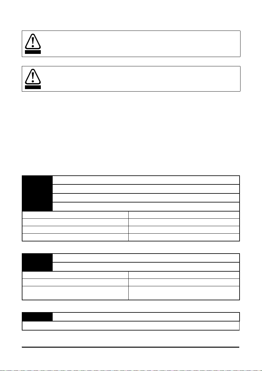
1.1 Warnings, Cautions and Notes
A Warning contains information, which is essential for avoiding a safety hazard.
A Caution contains information, which is necessary for avoiding a risk of damage to the
product or other equipment.
A Note contains information, which helps to ensure correct operation of the product.
1.2 Electrical safety - general warning
The voltages used in the drive can cause severe electrical shock and/or burns, and could be lethal.
Extreme care is necessary at all times when working with or adjacent to the drive.
Specific warnings are given at the relevant places in this User Guide.
1.3 System design and safety of personnel
The drive is intended as a component for professional incorporation into complete equipment or a
system. If installed incorrectly, the drive may present a safety hazard.
The drive uses high voltages and currents, carries a high level of stored electrical energy, and is
used to control equipment which can cause injury.
Close attention is required to the electrical installation and the system design to avoid hazards
either in normal operation or in the event of equipment malfunction. System design, installation,
commissioning/start-up and maintenance must be carried out by personnel who have the
necessary training and experience. They must read this safety information and this User Guide
carefully.
The STOP and SAFE TORQUE OFF functions of the drive do not isolate dangerous voltages from
the output of the drive or from any external option unit. The supply must be disconnected by an
approved electrical isolation device before gaining access to the electrical connections.
With the sole exception of the SAFE TORQUE OFF function, none of the drive functions
must be used to ensure safety of personnel, i.e. they must not be used for safety-related
functions.
Careful consideration must be given to the functions of the drive which might result in a hazard,
either through their intended behavior or through incorrect operation due to a fault. In any
application where a malfunction of the drive or its control system could lead to or allow damage,
loss or injury, a risk analysis must be carried out, and where necessary, further measures taken to
reduce the risk - for example, an over-speed protection device in case of failure of the speed
control, or a fail-safe mechanical brake in case of loss of motor braking.
The system designer is responsible for ensuring that the complete system is safe and
designed correctly according to the relevant safety standards.
Introduction
Mechanical
installation
installation
Electrical
Parameters
Variable allocation
menus
Digital I/O
Timer
programming
User
Diagnostics Index
MCi210 User Guide 5
Issue Number: 2
Page 6

1.4 Environmental limits
Instructions regarding transport, storage, installation and use of the drive must be complied with,
including the specified environmental limits. These instructions can be found in the relevant drive
documentation. Drives must not be subjected to excessive physical force.
1.5 Access
Drive access must be restricted to authorized personnel only. Safety regulations which apply at the
place of use must be complied with.
1.6 Compliance with regulations
The installer is responsible for complying with all relevant regulations, such as national wiring
regulations, accident prevention regulations and electromagnetic compatibility (EMC) regulations.
Particular attention must be given to the cross-sectional areas of conductors, the selection of fuses
or other protection, and protective ground (earth) connections.
Instructions for achieving compliance with specific EMC standards may be found in the relevant
drive documentation.
Within the European Union, all machinery in which this product is used must comply with the
following directives:
2006/42/EC: Safety of machinery.
2004/108/EC: Electromagnetic Compatibility.
1.7 Adjusting parameters
Some parameters have a profound effect on the operation of the drive. They must not be altered
without careful consideration of the impact on the controlled system. Measures must be taken to
prevent unwanted changes due to error or tampering.
1.8 Stored charge
The drive contains capacitors which remain charged to a potentially lethal voltage after the AC
supply has been disconnected. If the drive has been energized, the AC supply must be isolated for
at least ten minutes before work may continue.
6 MCi210 User Guide
Issue Number: 2
Page 7

2 Introduction
information
Safety
2.1 MCi210 module
The MCi210 is a CoDeSys-based user-programmable option module for Unidrive M. It is an
intelligent module that expands on the functionality of the Unidrive M by offering the following
features:
• CoDeSys based user programming
• Digital I/O
• Timer Unit
• Onboard Ethernet (2 ports)
• File system
2.2 User programming
The MCi210 module is capable of running a CoDeSys program created by a user with the Machine
Control Studio (MC Studio) software. It is an integrated development environment that supports all
five of the programming languages of the IEC 61131-3 standard, including Structured Text (ST),
Ladder Diagram (LD), Function Block Diagram (FBD), Sequential Function Chart (SFC) and
Instruction List (IL). Continuous Function Chart (CFC) is also supported.
The user has a number of tasks available to them. These are documented below.
• Initial
• Freewheeling
• Clock0
• Clock1
• Clock2
• Clock3
•Position
• Event0
• Event1
• Event2
• Event3
•ErrorTask
The Freewheeling, Clockn and Position tasks are cyclic tasks. The Clockn and Position tasks will
run at an interval set by the user in MC Studio. The Freewheeling task is the lowest priority task and
will run when processor resource allows.
Introduction
Mechanical
installation
installation
Electrical
Parameters
Variable allocation
menus
Digital I/O
Timer
MCi210 User Guide 7
Issue Number: 2
programming
User
Diagnostics Index
Page 8
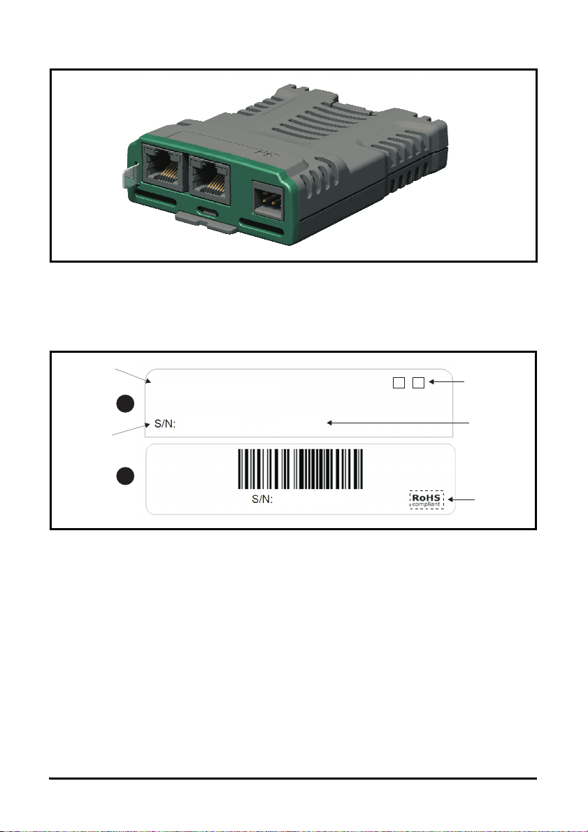
2.3 Option module identification
1
2
MCi210
3000005001
STDN39
AB
3000005001
Option module
name
Ethernet link /
activity indicators
Serial number
Date code
Approval
Figure 2-1 MCi210 module
The MCi210 module can be identified by:
1. The label located on the topside of the option module.
2. The color coding across the front of the option module and the connector types.
MCi210: Moss green with two 8P8C (RJ45) connectors and a 6-way pluggable connector.
Figure 2-2 MCi210 label
1: Topside module label
2: Underside module label
2.4 Conventions used in this guide
The configuration of the host drive and System Integration option module is performed using
menus and parameters. A menu is a logical collection of parameters that have similar functionality.
The MCi210 module contains a number of menus that are grouped by the slot number that the
module is installed into.
The method used to determine the menu or parameter is as follows:
•Pr S.mm.ppp - signifies a module parameter, where S is the slot number that the module is
installed in, mm is the module menu number and ppp is the parameter within that menu.
•Pr mm.000 - signifies any drive menu and parameter number 00.
8 MCi210 User Guide
Issue Number: 2
Page 9
3 Mechanical installation
WARNING
Before installing or removing an option module from any drive, ensure the AC supply
has been disconnected for at least 10 minutes and refer to Chapter 1 Safety
information on page 5. If using a DC bus supply ensure this is fully discharged before
working on any drive or option module.
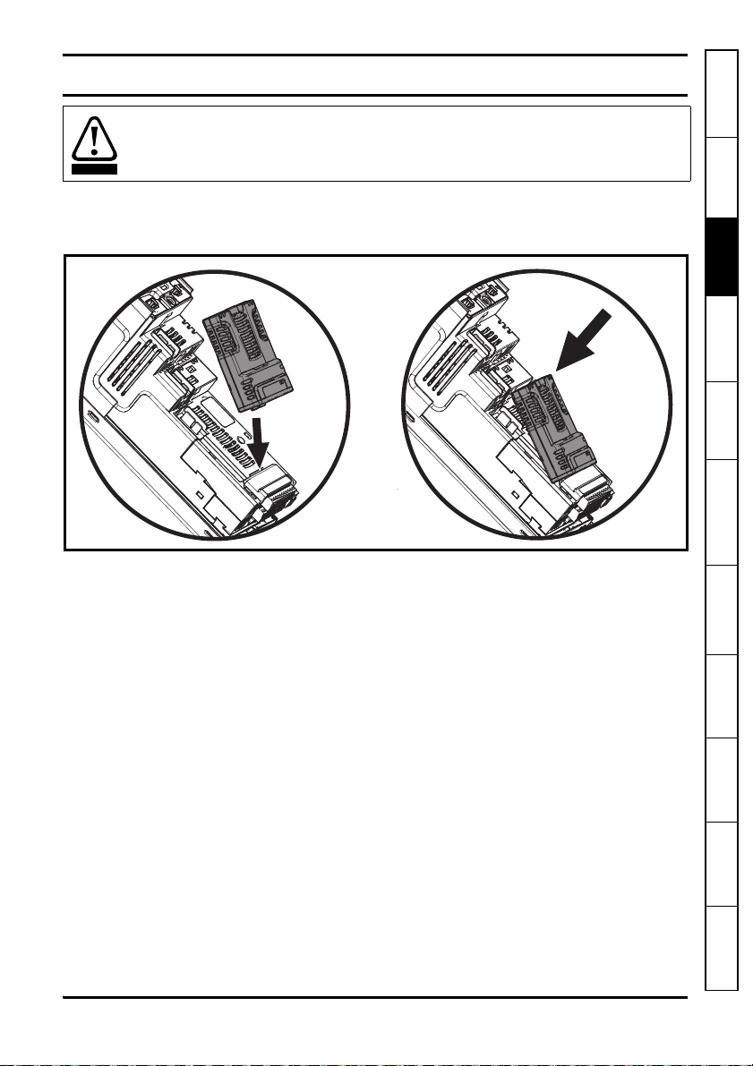
3.1 General Installation
The installation of an option module is illustrated in Figure 3-1.
Figure 3-1 Option module installation
information
Safety
Introduction
Mechanical
installation
installation
Electrical
Parameters
Variable allocation
menus
3.1.1 Installing the first option module
Option module slots must be used in the following order: slot 3, slot 2 and slot 1.
• Align the option module above the drive as shown
• Insert the option module tab into the slot on the drive
• Press down on the option module until it clicks into place
MCi210 User Guide 9
Issue Number: 2
Digital I/O
Timer
programming
User
Diagnostics Index
Page 10
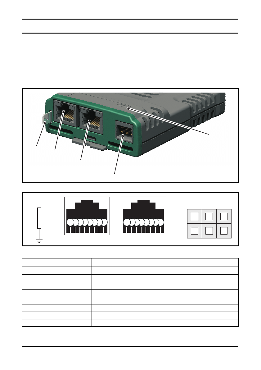
4 Electrical installation
Ethernet
port A
Ethernet
port B
Link LEDs
Digital I/O
Ground
tab
123
Digital I/O
Spade
connector
1234567812345678
456
4.1 MCi210 module information
The MCi210 module provides two standard 8P8C (RJ45) UTP/STP (Un-shielded / Shielded
Twisted Pair) connections to a 100 Mbps Ethernet network using an inbuilt switch. A grounding tab
is provided for supplementary bonding of the 8P8C connectors. A link/activity indicator is provided
for each of the Ethernet ports. The indicators are located on the top surface of the module.
The MCi210 module also provides a 6-way pluggable connector for digital inputs and outputs.
Figure 4-1 MCi210
Figure 4-2 MCi210 Connections
Table 4-3 8P8C (RJ45) Ethernet port connector pin out
Terminal Description
1 Transmit +
2 Transmit -
3 Receive +
4N/A
5N/A
6 Receive -
7N/A
8N/A
10 MCi210 User Guide
Issue Number: 2
Page 11

Table 4-4 6-way digital I/O pluggable connector pin out
Terminal Description
1 Digital input 1
2 Digital input 2
3 Digital input 3
4 Digital I/O 4
5 Digital output 5
6 0 V common
4.2 Ethernet
4.2.1 Isolation
The shells of the 8P8C (RJ45) Ethernet ports are isolated from 0V of the module and the drive.
The ground tab on the MCi210 module is not required for electrical safety and is available only to
increase immunity from electrical noise.
4.2.2 Cabling
Standard UTP (unshielded twisted pair) or STP (shielded twisted pair) cables are supported. It is
recommended that a minimum specification CAT5e is used in new installations.
The Ethernet interface on the module supports the 'Auto cross-over detection', therefore a crossover cable is not required when connecting the Ethernet port on the module directly to the Ethernet
port of a PC.
4.2.3 Link / activity indicators
Each Ethernet port has a corresponding link / activity indicator on the topside of the module as
shown in Figure 4-1. Table 4-5 below details the different statuses of the indicators.
Table 4-5 Ethernet link / activity indicator status
Indicator status Description
Off Ethernet connection not detected
Solid green Ethernet connection detected but no data
Flashing green Ethernet connection detected and data flow
information
Safety
Introduction
Mechanical
installation
installation
Electrical
Parameters
Variable allocation
menus
Digital I/O Timer
MCi210 User Guide 11
Issue Number: 2
programming
User
Diagnostics Index
Page 12
4.3 Digital I/O
WARNING
WARNING
The digital I/O circuits are isolated from the power circuits in the drive by basic insulation
(single insulation) only. The installer must ensure that the external control circuits are
insulated from human contact by at least one layer of insulation (supplementary
insulation) rated for use at the AC supply voltage.
If the digital inputs or outputs are to be connected to other circuits classified as Safety
Extra Low Voltage (SELV) (e.g. to a personal computer), an additional isolating barrier
must be included in order to maintain the SELV classification.
The MCi210 is equipped with 3 digital inputs, 1 selectable digital input or output and 1 digital output.
These inputs and outputs can be read to or controlled by the user program in the module.
The digital outputs are a positive logic arrangement with high side drivers only, such that they are at
+24 V when active and can supply a total maximum 20 mA of current shared between the two
outputs. When inactive they are effectively floating. The digital outputs are protected against shortcircuit or overload. The trip threshold is 20 mA, and if tripped both outputs will be deactivated and
the drive will show a "Slotx Error - Output overload" trip (where x indicates the slot number that
module is installed in).
The digital I/O are controlled using menu 4 in the module. Refer to section 5.9 Menu 4 - Digital I/
O on page 35 for more information.
4.3.1 Digital I/O specifications
1 Digital Input 1
2 Digital Input 2
3 Digital Input 3
4 Digital I/O 4 (when configured as an input)
Type Positive logic IEC 61131-2
Maximum input voltage ±30 V
Switching threshold 9.5 V ±0.3 V
Load >2 mA at 15 V
4 Digital I/O 4 (when configured as an output)
5 Digital output 5
Type Positive logic
Output voltage 0 V to 24 V
Maximum output current
6 0 V common
Common to the 0 V of the host drive
20 mA (from one output only or shared between
both outputs)
12 MCi210 User Guide
Issue Number: 2
Page 13

5 Parameters
information
Safety
5.1 Overview
The MCi210 module holds two parameter databases; the MCi210 database and the database for
the drive to which the module is installed.
The MCi210 database parameters can be accessed from the drive’s keypad, a user program in the
MCi210, PC Tools or a module in another slot of the drive. The notation S.mm.ppp is used to
access these parameters where S is the slot number, mm is the menu number and ppp is the
parameter number. For example, to access Pr 03.010 of an MCi210 installed in slot 2 of a drive
from a module in slot 3 it will be accessed using Pr 2.3.010.
The MCi210 module will also hold a copy of the host drive’s database. At power up, if the database
held in the MCi210 is different to that of the drive, the MCi210 will upload the drive's database and
overwrite the stored database. If the two databases match the drive's database will not be
uploaded.
A module that is powered up for the first time will not contain a drive database and therefore will
always perform a drive database upload.
5.2 Menus
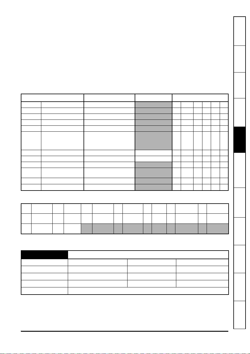
Table 5-1 below details each of the module's internal menus.
Table 5-1 MCi210 Internal Menu descriptions
Menu Name Description
MCi210 module
S.0
information
S.1 User application Allows the user program to be controlled and monitored
S.2 Ethernet configuration Allows the Ethernet interface to be configured
S.3 Timer Allows the timer unit to be controlled
S.4 Digital I/O Allow the digital I/O to be controlled or monitored
S.9 Resources
S.10 Easy mode cyclic data Allows Ethernet cyclic data links to be configured
S.11 Synchronization
S.15 Modbus
Where S is the slot number that the module is installed in.
The module's menu 0 is also displayed in menu 15, 16 or 17 on the drive depending on which slot
the module is installed in. MC Studio can be used to set up a custom or application menu for the
module and if set up, the custom menu will be displayed in menu 25, 26 or 27 depending on which
slot the module is installed in. Table 5-2 below shows the location of module's menu 0 and custom
menu on the drive.
Provides module information such as firmware version and serial
number
Provides information regarding the resources of the Ethernet
interface and module temperature
Allows the Ethernet based synchronization to be set-up and
monitored
Allow the Modbus protocol supported by the Ethernet interface to
be set-up
Introduction
Mechanical
installation
installation
Electrical
Parameters
Variable allocation
menus
Digital I/O
Timer
programming
User
Diagnostics Index
MCi210 User Guide 13
Issue Number: 2
Page 14

Table 5-2 Module's menu 0 and custom menu locations on the drive
Slot number Module’s Menu 0 location
115 25
216 26
317 27
Custom / Application
menu location
5.3 Parameter save and restore
Any user-save parameters in the option module's internal menus are stored in non-volatile memory
on the module and not in the drive. Therefore, if the module is moved to a different slot or to a
different drive then any saved parameter values will follow the module. If a module is to be
replaced, ensure that the parameter values for the module have been backed up before replacing
it.
5.4 Remanent variables
The module supports both Retain and Persistent variables. Both of these types of variable allow
values to be retained after a power-cycle or module reset, however there is a difference between
Retain and Persistent variables.
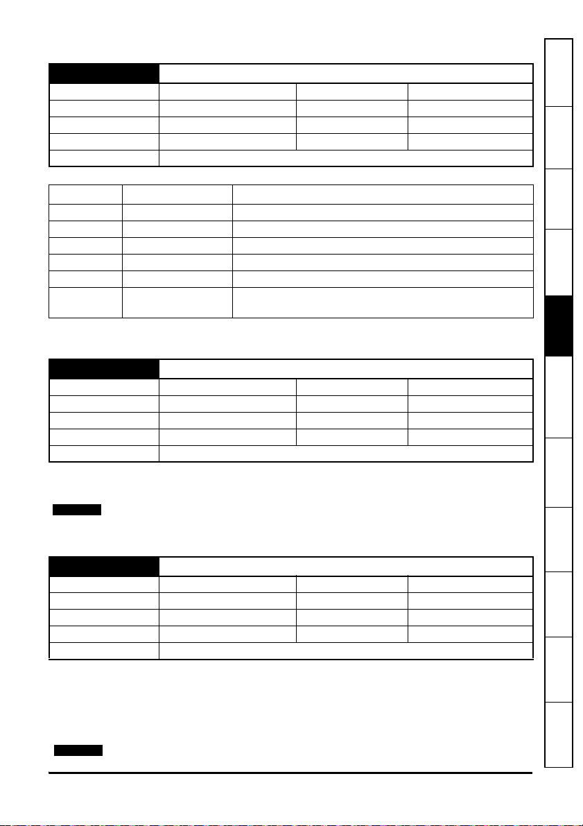
The following table indicates the behaviour of all variable types:
VAR PERSISTENT
Command VAR VAR RETAIN
Reset warm - X X
Reset cold - - X
Reset origin - - -
Online change X X X
Reboot module - X X
Key:
X = Value is maintained
- = Value is initialized
VAR RETAIN PERSISTENT
VAR PERSISTENT RETAIN
RETAIN variables are declared in MC Studio as shown below:
VAR RETAIN
iRem1 : INT; (* 1. Retain variable*)
END_VAR
PERSISTENT variables are declared in MC Studio as shown below:
VAR_GLOBAL PERSISTENT RETAIN
iVarPers1 : DINT; (* 1. Persistent+Retain Variable App1 *)
bVarPers : BOOL; (* 2. Persistent+Retain Variable App1 *)
END_VAR
14 MCi210 User Guide
Issue Number: 2
Page 15
5.4.1 Reset warm
A reset warm is performed from the MC Studio software and will reset only standard variables to
their initialisation values.
5.4.2 Reset cold
A reset cold can be performed from the drive's keypad or MC Studio and will reset RETAIN and
standard variables to their initialisation values.
5.4.3 Reset origin
This reset will reset all (including RETAIN and PERSISTENT) variables to their initialisation values
and will erase the application on the module. This can only be performed from MC Studio.
5.5 Menu 0 - MCi210 Module information
Parameter Range Default Type
S.00.001 Module ID 0 to 65535 RO Num ND NC PT
S.00.002 Software Version 00.00.00.00 to 99.99.99.99 RO Num ND NC PT
S.00.003 Hardware Version 0.00 to 99.99 RO Num ND NC PT
S.00.004 Serial Number LS 0 to 99999999 RO Num ND NC PT
S.00.005 Serial Number MS 0 to 99999999 RO Num ND NC PT
Bootldr-Update (-2),
S.00.006 Module Status
S.00.007 Reset Module Off (0) or On (1) Off (0) RW Bit NC
S.00.008 Default Module Off (0) or On (1) Off (0) RW Bit NC
S.00.009 Ac ti ve A la r m B it s 0 to 1111111111111111 RO Bin NC
S.00.010 Active IP Address
S.00.030 Slot Number Indicator 0 to 8 RO Num ND NC PT
S.00.031 Slot Menu Number 0 to 255 RO Num ND NC PT
Bootldr-Idle (-1),
Initializing (0), OK (1),
Config (2), Error (3)
128.000.000.000 to
127.255.255.255
RO Txt ND NC PT
RO IP NC
information
Safety
Introduction
Mechanical
installation
installation
Electrical
Parameters
Variable allocation
menus
Digital I/O
Read /
RW
Write
No default
ND
value
IP IP address Mac
RO
NC
Read
only
Not
copied
Mac
address
Num
PT
Number
parameter
Protected
parameter
Bit
RA
Bit
parameter
Rating
dependent
Txt
US
Text
string
User
save
Bin
PS
Binary
parameter
Powerdown save
FI Filtered
DE Destination
S.00.001 Module ID
Minimum 0 Maximum 65535
Default 310 Units
Type 16 Bit Volatile Update Rate Power-up write
Display Format None Decimal Places 0
Coding RO, ND, NC, PT, BU
This parameter shows the Module ID. This is 310 for the MCi210 module.
MCi210 User Guide 15
Issue Number: 2
Timer
programming
User
Diagnostics Index
Page 16

S.00.002 Software Version
Minimum 0 (Display: 00.00.00.00) Maximum
Default Units
Type 32 Bit Volatile Update Rate Power-up write
Display Format Version Number Decimal Places 0
Coding RO, ND, NC, PT
This parameter shows the Module firmware version in ww.xx.yy.zz format
S.00.003 Hardware Version
Minimum 0.00 Maximum 99.99
Default Units
Type 16 Bit Volatile Update Rate Power-up write
Display Format None Decimal Places 2
Coding RO, ND, NC, PT
This parameter shows the hardware version of the module.
S.00.004 Serial Number LS
Minimum 0 Maximum 99999999
Default Units
Type 32 Bit Volatile Update Rate Power-up write
Display Format None Decimal Places 0
Coding RO, ND, NC, PT
999999
(Display: 99.99.99.99)
S.00.005 Serial Number MS
Minimum 0 Maximum 99999999
Default Units
Type 32 Bit Volatile Update Rate Power-up write
Display Format None Decimal Places 0
Coding RO, ND, NC, PT
The module serial number is available as a pair of 32 bit values where Serial Number LS (S.00.004)
provides the least significant 8 decimal digits and Serial Number MS (S.00.005) provides the most
significant 8 decimal digits. The reconstructed serial number is ((S.00.005 x100000000) +
S.00.004). For example serial number "0001234567898765" would be stored as S.00.005 = 12345,
S.00.004 = 67898765.
16 MCi210 User Guide
Issue Number: 2
Page 17
S.00.006 Module Status
NOTE
NOTE
Minimum -2 Maximum 3
Default Units
Type 8 Bit Volatile Update Rate Background
Display Format None Decimal Places 0
Coding RO, Txt, ND, NC, PT
Value Text Description
-2 Bootldr - Update The bootloader is performing a flash update.
-1 Bootldr - Idle The bootloader is idle.
0 Initializing The module is initializing
1 OK Module is initialized with no errors present
2 Config A configuration error has been detected
3Error
An error has occured preventing the module from running
correctly
This parameter shows the status of the module.
S.00.007 Reset Module
Minimum 0 Maximum 1
Default 0 Units
Type 1 Bit Volatile Update Rate Read every 200 ms
Display Format None Decimal Places 0
Coding RW, NC
When set the module performs a warm reset. When the reset has been performed and the module
is performing its initialization routines the parameter will be cleared to zero.
information
Safety
Introduction
Mechanical
installation
installation
Electrical
Parameters
Variable allocation
menus
Digital I/O
The drive, and any other modules installed to the drive will not be affected by the reset.
S.00.008 Default Module
Minimum 0 Maximum 1
Default 0 Units
Type 1 Bit Volatile Update Rate Read on reset
Display Format None Decimal Places 0
Coding RW, NC
To default the module set this parameter to On (1) and perform a module reset. Once complete, this
parameter will return to Off (0). Defaulting the module will cause it to return to its "Out of Box
configuration" and any settings stored on the module will be returned to their default values. This
will include any web page customizations, e-mail settings, etc.
Take care using this parameter as any configuration information will be irretrievably lost.
The password for the 'root' account is not reset back to default.
MCi210 User Guide 17
Issue Number: 2
Timer
programming
User
Diagnostics Index
Page 18

S.00.009 Active Alarm Bits
Minimum 0 (Display: 0) Maximum
Default Units
Type 16 Bit Volatile Update Rate Background
Display Format Binary Decimal Places 0
Coding RO, NC, BU
Bit Alarm
0 User Program
1eCMP
2 Modbus
3 Ethernet/IP
4 Reserved
5File System
6 Module Too Hot
This parameter displays the currently active alarms. Each bit represents an alarm as detailed in the
table above.
S.00.010 Active IP Address
Minimum
Default Units
Type 32 Bit Volatile Update Rate Background
Display Format IP Address Decimal Places 0
Coding RO, NC, PT
This parameter shows the active IP Address of the module.
-2147483648
(Display: 128.0.0.0)
Maximum
65535
(D ispla y:1111111111111111)
2147483647
(Display:
127.255.255.255)
S.00.030 Slot Number Indicator
Minimum 0 Maximum 8
Default Units
Type 8 Bit Volatile Update Rate Written on power-up
Display Format None Decimal Places 0
Coding RO, ND, NC, PT, BU
This parameter shows the slot number that the module is installed in.
18 MCi210 User Guide
Issue Number: 2
Page 19
S.00.031 Slot Menu Number
Minimum 0 Maximum 255
Default Units
Type 8 Bit Volatile Update Rate Written on power-up
Display Format None Decimal Places 0
Coding RO, ND, NC, PT, BU
This parameter shows the drive menu number associated with the slot that the module is installed
in.
For example:
• If the module is installed in slot 1, this parameter will show 15.
• If the module is installed in slot 2, this parameter will show 16.
• If the module is installed in slot 3, this parameter will show 17.
5.6 Menu 1 - User Application
information
Safety
Introduction
Mechanical
installation
installation
Electrical
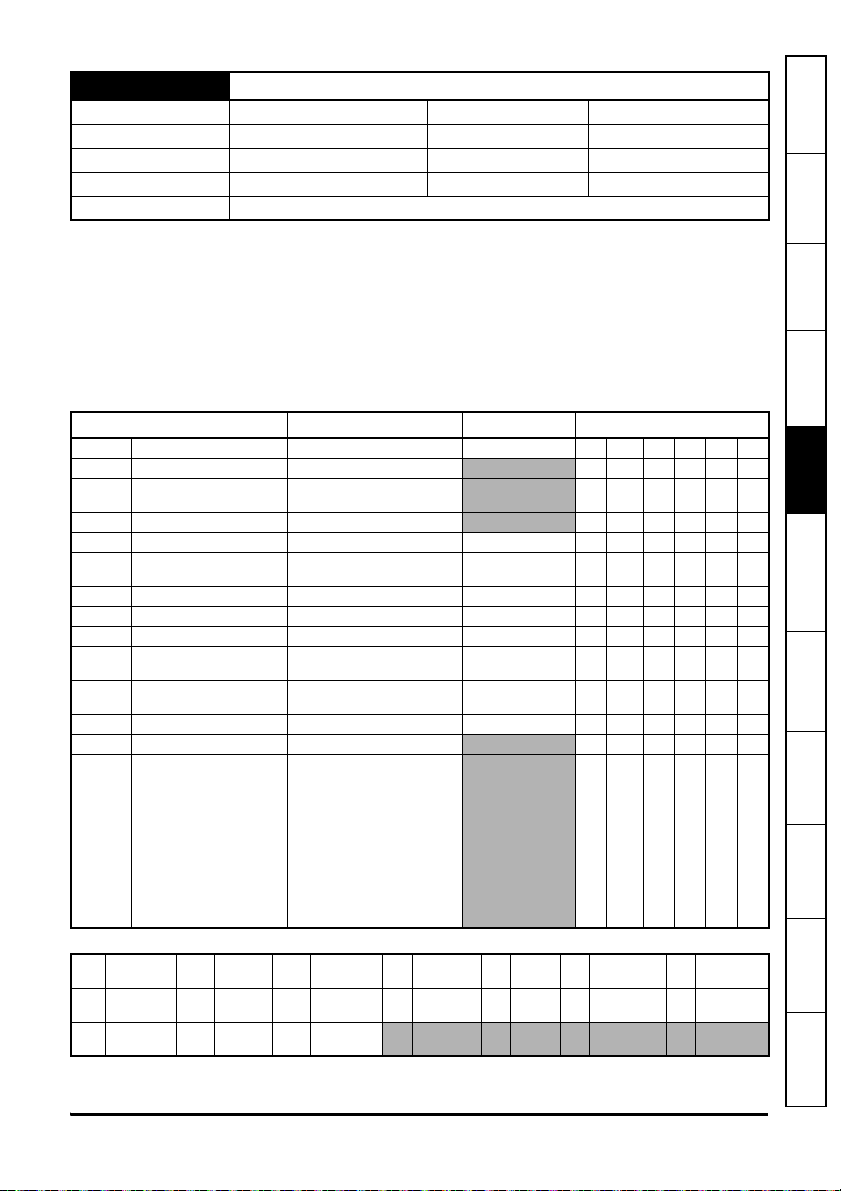
Parameter Range Default Type
S.01.001 Selected UCI Number 0 to 9 0 RW Num ND NC PT
S.01.002 Active UCI Number 0 to 9 RO Num ND NC PT
S.01.003 User Program Status
S.01.004 Available CPU Resources 0 to 100 % RO Num ND PT
S.01.013 Auto-run Enable Off (0), or On (1) On (1) RW Bit US
Global Run-time Trip
S.01.014
Enable
S.01.015 Disable Reset on trip Clear Off (0), or On (1) Off (0) RW Bit US
S.01.017 Enable Out of Range Error Off (0), or On (1) Off (0) RW Bit US
S.01.019 Save Retain Data Request Off (0), or On (1) Off (0) RW Bit NC
Power Down Retain Data
S.01.020
Save
Under Voltage State User
S.01.021
Program Behaviour
S.01.025 Reserved 0 to 2147483647 0 RW
S.01.049 Run time error code 0 to 8448 RO Num ND PT
S.01.050 Run time error task ID
Read /
RW
Write
No default
ND
value
IP IP address Mac
RO
NC
Read
only
Not
copied
Mac
address
None (0), Stopped (1),
Run (2), Error (3)
Off (0), or On (1) Off (0) RW Bit US
Disabled (0), UV (1),
UV (no 24V) (2)
P-S-R (0), S-S-CR-RU (1),
S-S (2)
USER_TASK_INIT (0),
USER_TASK_EVENT0 (1),
USER_TASK_EVENT1 (2),
USER_TASK_EVENT2 (3),
USER_TASK_EVENT3 (4),
USER_TASK_POS (5),
USER_TASK_CLOCK0 (6),
USER_TASK_CLOCK1 (7),
USER_TASK_CLOCK2 (8),
USER_TASK_CLOCK3 (9),
USER_TASK_FWHEEL (10),
TASK_UNKNOWN (11)
Number
Num
PT
SMP
parameter
Protected
parameter
Slot menu
parameter
Bit
RA
Bit
parameter
Rating
dependent
Disabled (0) RW Txt US
S-S-CR-RU (1) RW Txt US
Text
Txt
string
User
US
save
RO Txt PT
RO Txt ND PT
Binary
Bin
parameter
Power-
PS
down save
FI Filtered
DE Destination
Parameters
Variable allocation
menus
Digital I/O
Timer
programming
User
Diagnostics Index
MCi210 User Guide 19
Issue Number: 2
Page 20

S.01.001 Selected UCI number
Minimum 0 Maximum 9
Default 0 Units
Type 8 Bit Volatile Update Rate
Display Format None Decimal Places 0
Coding RW, ND, NC, PT, BU
This parameter specifies which User Customizable Image folder is currently selected and therefore
which user program is launched when the module is initialized. The currently selected folder is used
for any PC Tool downloads and may not be the same as the Active UCI Number.
This allows for multiple user programs / customizations to be stored in the option module. If the
selected UCI has been changed the module must be reset for the new application to become
active.
Please note the difference between the Selected UCI and the Active UCI (Active UCI number
(S.01.002)). The Selected UCI is the image that the user wishes to be active after a module reset,
the Active UCI displays the UCI image currently active.
S.01.002 Active UCI number
Minimum 0 Maximum 9
Default Units
Type 8 Bit Volatile Update Rate Background write
Display Format None Decimal Places 0
Coding RO, ND, NC, PT, BU
This parameter indicates the currently active UCI. All user program control and state parameters
and command relate to the Active UCI except for user program download via eCMP. This allows for
downloading to one UCI folder while running from another.
Note the difference between the Selected UCI (Selected UCI number (S.01.001)) and the Active
UCI. The Selected UCI is the image that the user wishes to be active after a module reset, the
Active UCI displays the UCI image currently active.
Read during
initialization
S.01.003 User Program Status
Minimum 0 Maximum 3
Default Units
Type 8 Bit Volatile Update Rate Background write
Display Format None Decimal Places 0
Coding RO, Txt, ND, PT, BU
This parameter indicates the status of a user program, if it is present. If no user program is present
in the module then it will also indicate this.
If the status indicates a run-time error (3, Error) the user's Error task may be running otherwise the
user program will have stopped.
20 MCi210 User Guide
Issue Number: 2
Page 21

Value Text Description
0 None No user program is present
1 Stopped The user program is not running
2 Run The user program is running
3 Error Run-time error
If the module contains a user program this parameter displays its status otherwise it displays 0 (no
program present).
S.01.004 Available CPU Resources
Minimum 0 Maximum 100
Default Units %
Type 8 Bit Volatile Update Rate Written every 1 s
Display Format None Decimal Places 0
Coding RO, ND, PT, BU
This parameter is updated once per second and shows the average resource free (amount of CPU
resources available for the user non-cyclic tasks) during that period. This parameter is not
calculated synchronously with the cyclic task(s).
Cyclic tasks, with the exception of the freewheeling task, have a higher priority and will normally
have a duration of less than one second so this parameter will give an indication of the average
system free resource, but if cyclic tasks execute for more than one second without being
rescheduled this parameter may show 0 % resource free, as during the most recent sample period
the cyclic tasks took all of the system resource. This is normal.
This parameter is calculated only when the user program is running. When the user program is not
running the parameter is set to 100 %.
information
Safety
Introduction
Mechanical
installation
installation
Electrical
Parameters
Variable allocation
menus
Digital I/O
S.01.013 Auto-run enable
Minimum 0 Maximum 1
Default 1 Units
Type 1 Bit User Save Update Rate
Read during
initialization
Display Format None Decimal Places 0
Coding RW, NR, BU
When set to 1 (On) the user program will start automatically on a module reset or at power up.
S.01.014 Global run-time trip enable
Minimum 0 Maximum 1
Default 0 Units
Type 1 Bit User Save Update Rate
Read during
initialization
Display Format None Decimal Places 0
Coding RW
When set to 1 (On) the module may cause the drive to trip when a run-time error occurs.
MCi210 User Guide 21
Issue Number: 2
Timer
programming
User
Diagnostics Index
Page 22

S.01.015 Disable reset on trip clear
Minimum 0 Maximum 1
Default 0 Units
Type 1 Bit User Save Update Rate Background read
Display Format None Decimal Places 0
Coding RW
When this parameter is 0 the module will reset when a drive trip is cleared. When the parameter is
set to On, the module will continue running (i.e. not reset) when a drive trip is cleared.
S.01.017 Enable out of range error
Minimum 0 Maximum 1
Default 0 Units
Type 16 Bit Volatile Update Rate Background read
Display Format None Decimal Places 0
Coding RW
When this parameter is 0, and an out of range value is written to a parameter, then the value will be
automatically limited to that parameter's maximum or minimum value.
When this parameter is 1, and an out of range value is written to a parameter, then a run-time error
(code 44) will occur.
S.01.019 Save retain data request
Minimum 0 Maximum 1
Default 0 Units
Type 1 Bit Volatile Update Rate Read every 200 ms
Display Format None Decimal Places 0
Coding RW, NC
When set the module will save any retain data that the user has defined, up to a maximum of 2 kB.
When the save is complete, the parameter will be cleared to zero. The save will be processed as a
background task and will not affect any scheduled user tasks.
S.01.020 Power down retain data save
Minimum 0 Maximum 2
Default 1 Units
Type 8 Bit User Save Update Rate
Display Format None Decimal Places 0
Coding RW, Txt, NC
The parameter allows the user to define the action on the retain data when the drive enters under
voltage state.
When set to 0 no action will be taken and the retain data will not be saved.
When set to 1 the retain data will be automatically saved when the drive enters the under voltage
state.
When Under Voltage is
detected
22 MCi210 User Guide
Issue Number: 2
Page 23

When set to 2 the retain data will be automatically saved when the drive enters the under voltage
state, but only if no 24 V backup supply is detected.
Value Text Description
0 Disabled Retain data not automatically saved
1 UV Retain data automatically saved on under voltage
2 UV (no 24V)
Retain data saved on under voltage AND no 24 V backup supply
detected
S.01.021 Under voltage state user program behaviour
Minimum 0 Maximum 2
Default 1 Units
Read when an Under
Type 8 Bit User Save Update Rate
Voltage is detected and
S.01.020 is set to a nonzero value
Display Format None Decimal Places 0
Coding RW, Txt, BU
Value Text Description
0P-S-R
Pause-Save Data- Resume (User Program may trip due task
overrun)
1 S-S-CR-RU Stop-Save-ColdReset-RUn
2 S-S Stop-Save
This parameter defines the user program behaviour when the module detects an Under Voltage
(UV) state.
The action of save resistant / persistent data depends on parameter S.01.020.
information
Safety
Introduction
Mechanical
installation
installation
Electrical
Parameters
Variable allocation
menus
Digital I/O
S.01.049 Run time error code
Minimum 0 Maximum 8448
Default 0 Units
Type 16 Bit Volatile Update Rate Written every second
Display Format None Decimal Places 0
Coding RO, ND, PT, BU
This parameter displays the code for the currently active run-time error.
MCi210 User Guide 23
Issue Number: 2
Timer
programming
User
Diagnostics Index
Page 24

S.01.050 Run time error task ID
Minimum 0 Maximum 11
Default 0 Units
Type 8 Bit Volatile Update Rate Written every second
Display Format None Decimal Places 0
Coding RO, Txt, ND, PT, BU
Value Text
0 USER_TASK_INIT
1 USER_TASK_EVENT0
2 USER_TASK_EVENT1
3 USER_TASK_EVENT2
4 USER_TASK_EVENT3
5 USER_TASK_POS
6 USER_TASK_CLOCK0
7 USER_TASK_CLOCK1
8 USER_TASK_CLOCK2
9 USER_TASK_CLOCK3
10 USER_TASK_FWHEEL
11 TASK_UNKNOWN
This parameter displays the task in error for the currently active run-time error.
24 MCi210 User Guide
Issue Number: 2
Page 25

5.7 Menu 2 - Ethernet configuration
Parameter Range Default Type
Initializing (0),
S.02.003 Network Status
S.02.004
S.02.005 DHCP Enable Off (0) or On (1) On (1) RW Bit US
S.02.006 IP Address
S.02.007 Subnet Mask
S.02.008 Default Gateway
S.02.009 Primary DNS
S.02.010 Secondary DNS
S.02.011 MAC Address
S.02.020 Priority Protocol
S.02.021 Web Server Enable Off (0) or On (1) On (1) RW Bit US
S.02.022 Web Server Port 0 to 65535 80 RW Num US
S.02.023 Email Enable Off (0) or On (1) On (1) RW Bit US
S.02.024 Ethernet MTU 158 to 1500 1500 RW Num US
S.02.025 Gateway Mode
S.02.030 VLAN Enable Off (0) or On (1) Off (0) RW Bit US
S.02.031 VLAN ID 0 to 255 0 RW Num US
Network Message
Count
Links Down (1),
DHCP In Progress (2),
No Address (3),
Ready (4), Active (5)
0 to 65535 RO Num ND NC PT
000.000.000.000 to
255.255.255.255
000.000.000.000 to
255.255.255.255
000.000.000.000 to
255.255.255.255
000.000.000.000 to
255.255.255.255
000.000.000.000 to
255.255.255.255
00:00:00:00:00:00 to
FF:FF:FF:FF:FF:FF
None (0), Modbus TCP (1),
Ethernet/IP (2)
Switch (0), Gateway (1),
Strict Gateway (2)
192.168.001.100 RW IP US
255.255.255.000 RW IP US
192.168.1.254 RW IP US
000.000.000.000 RW IP US
000.000.000.000 RW IP US
0RWTxt US
Switch (0) RW Txt US
RO Txt ND NC PT
RO Mac ND NC PT
information
Safety
Introduction
Mechanical
installation
installation
Electrical
Parameters
Variable allocation
menus
Digital I/O
Read /
RW
Write
No default
ND
value
IP IP address Mac
RO
NC
Read
only
Not
copied
Mac
address
Num
PT
SMP
Number
parameter
Protected
parameter
Slot menu
parameter
Bit
RA
Bit
parameter
Rating
dependent
Txt
US
Text
string
User
save
Bin
PS
Binary
parameter
Powerdown save
FI Filtered
DE Destination
MCi210 User Guide 25
Issue Number: 2
Timer
programming
User
Diagnostics Index
Page 26

S.02.003 Network Status
Minimum 0 Maximum 5
Default Units
Type 8 Bit Volatile Update Rate Written every second
Display Format None Decimal Places 0
Coding RO, Txt, ND, NC, PT, BU
Value Text Description
0 Initializing The network interface is being initialized
1 Links Down
2 DHCP In Progress
3 No Address
4 Ready
5 Active The network interface is receiving or transmitting data
This parameter indicates the status of the network that the module is connected to.
S.02.004 Network Message Count
Minimum 0 Maximum 65535
Default Units Messages/s
Type 16 Bit Volatile Update Rate Written every second
Display Format None Decimal Places 0
Coding RO, ND, NC, PT, BU
The number of frames that the module is transmitting / receiving every second.
No link connection has been detected on either of the Ethernet
ports
The module is attempting to obtain an IP Address, subnet mask,
default gateway and DNS server addresses from a DHCP server
The module does not have an IP Address - either the user has
not provided one manually or one could not be allocated via
DHCP
The network interface has been successfully configured but no
data is being received or transmitted
S.02.005 DHCP Enable
Minimum 0 Maximum 1
Default 1 Units
Type 1 Bit User Save Update Rate Background read
Display Format None Decimal Places 0
Coding RW, BU
This parameter controls whether or not the module will attempt to use a Dynamic Host
Configuration Protocol (DHCP) server to obtain an IP Address, subnet mask, default gateway and
DNS servers.
26 MCi210 User Guide
Issue Number: 2
Page 27

When DHCP is enabled, the following parameters will become read-only immediately (no reset
required):
IP Address (S.02.006)
Subnet Mask (S.02.007)
Default Gateway (S.02.008)
Primary DNS (S.02.009)
Secondary DNS (S.02.010)
information
Introduction
Safety
S.02.006 IP Address
Minimum 0 (Display: 0.0.0.0) Maximum
Default
3232235876
(Display: 192.168.1.100)
Units
4294967295
(Display: 255.255.255.255)
DHCP enabled : write on
Type 32 Bit User Save Update Rate
event; DHCP disabled :
read on reset
Display Format IP Address Decimal Places 0
Coding RW, BU
This parameter controls and displays the IP Address of the module.
If DHCP is enabled (DHCP Enable (S.02.005)) this parameter becomes read-only and, until an IP
Address is allocated to the module, will display 0.0.0.0.
If DHCP is disabled the module will initialize, on reset or power cycle, with the IP Address stored for
the parameter.
S.02.007 Subnet Mask
Minimum 0 (Display: 0.0.0.0) Maximum
Default
4294967040
(Display: 255.255.255.0)
Units
4294967295
(Display:255.255.255.255)
DHCP enabled : write on
Type 32 Bit User Save Update Rate
event; DHCP disabled :
read on reset
Display Format IP Address Decimal Places 0
Coding RW, BU
This parameter controls and displays the subnet mask of the module.
If DHCP is enabled (DHCP Enable (S.02.005)) this parameter becomes read-only and, until an IP
Address is allocated to the module, will display 0.0.0.0.
If DHCP is disabled the module will initialize, on reset or power cycle, with the subnet mask stored
for the parameter.
Mechanical
installation
installation
Electrical
Parameters
Variable allocation
menus
Digital I/O
Timer
programming
User
Diagnostics Index
MCi210 User Guide 27
Issue Number: 2
Page 28

S.02.008 Default Gateway
Minimum 0 (Display: 0.0.0.0) Maximum
Default
Type 32 Bit User Save Update Rate
Display Format IP Address Decimal Places 0
Coding RW, BU
This parameter controls and displays the default gateway of the module.
If DHCP is enabled (DHCP Enable (S.02.005)) this parameter becomes read-only and, until an IP
Address is allocated to the module, will display 0.0.0.0.
If DHCP is disabled the module will initialize, on reset or power cycle, with the default gateway
stored for the parameter.
S.02.009 Primary DNS
Minimum 0 (Display: 0.0.0.0) Maximum
Default 0 (Display: 0.0.0.0) Units
Type 32 Bit User Save Update Rate
Display Format IP Address Decimal Places 0
Coding RW, BU
The module can use this IP Address when it wishes to resolve the IP Address for a domain name.
This parameter performs the same function as the Secondary DNS parameter (Secondary DNS
(S.02.010)), however the address specified in this parameter will be tried first. Only when this
address is unsuccessful will the Secondary DNS address be tried.
If DHCP is enabled (DHCP Enable (S.02.005)) this parameter becomes read-only and, until an IP
Address is allocated to the module, will display 0.0.0.0.
If DHCP is disabled the module will initialize, on reset or power cycle, with the primary DNS
address stored for the parameter.
3232236030
(Display: 192.168.1.254)
Units
4294967295
(Display: 255.255.255.255)
DHCP enabled: write on
event;
DHCP disabled: read on
reset
4294967295
(Display:255.255.255.255)
DHCP enabled: write on
event;
DHCP disabled: read on
reset
28 MCi210 User Guide
Issue Number: 2
Page 29

S.02.010 Secondary DNS
Minimum 0 (Display: 0.0.0.0) Maximum
4294967295
(Display: 255.255.255.255)
Default 0 (Display: 0.0.0.0) Units
DHCP enabled: write on
Type 32 Bit User Save Update Rate
event;
DHCP disabled: read on
reset
Display Format IP Address Decimal Places 0
Coding RW, BU
The module can use this IP Address when it wishes to resolve the IP Address for a domain name.
This parameter performs the same function as the Primary DNS parameter (Primary DNS
(S.02.009)), however the address specified in this parameter will be tried only when the Primary
DNS address is unsuccessful.
If DHCP is enabled (DHCP Enable (S.02.005)) this parameter becomes read-only and, until a
secondary DNS address is allocated to the module, will display 0.0.0.0.
If DHCP is disabled the module will initialize, on reset or power cycle, with the secondary DNS
address stored for the parameter.
S.02.011 MAC Address
Minimum
0 (Display:
00:00:00:00:00:00)
Maximum
281474976710655
(Display: FF:FF:FF:FF:FF:FF)
Default Units
Type 64 Bit Volatile Update Rate Power-up write
Display Format Mac Address Decimal Places 0
Coding RO, ND, NC, PT, BU
This parameter shows the 48-bit MAC address of the module.
information
Safety
Introduction
Mechanical
installation
installation
Electrical
Parameters
Variable allocation
menus
Digital I/O
S.02.020 Priority Protocol
Minimum 0 Maximum 2
Default 0 Units
Type 8 Bit User Save Update Rate Background read
Display Format None Decimal Places 0
Coding RW, Txt, BU
This parameter enables the selection of the fieldbus protocol to have priority over all other
protocols. A tick period of 1 ms will be given to the highest priority fieldbus protocol, 5 ms to all
other fieldbus protocols (equal priority).
If no fieldbus protocol has been selected to have priority over others, all protocols will have equal
priority and a tick rate of 5 ms.
MCi210 User Guide 29
Issue Number: 2
Timer
programming
User
Diagnostics Index
Page 30

Value Text Description
0 None All protocols have equal priority
1 Modbus TCP Modbus TCP has highest priority
2 Ethernet/IP Ethernet/IP has highest priority
S.02.021 Web Server Enable
Minimum 0 Maximum 1
Default 1 Units
Type 1 Bit User Save Update Rate Background read
Display Format None Decimal Places 0
Coding RW, BU
This parameter controls the running of the webserver on the module.
S.02.022 Web Server Port
Minimum 0 Maximum 65535
Default 80 Units
Type 16 Bit User Save Update Rate
Display Format None Decimal Places 0
Coding RW, BU
This parameter shows the web server port. This may be changed for added security.
Read on module reset
and HTTP_ENABLE
S.02.024 Ethernet MTU
Minimum 158 Maximum 1500
Default 1500 Units Bytes
Type 16 Bit User Save Update Rate Read on module reset
Display Format None Decimal Places 0
Coding RW, BU
This parameter specifies the MTU (Maximum Transmittable Unit) in bytes allowed by the Ethernet
interface.
30 MCi210 User Guide
Issue Number: 2
Page 31

S.02.025 Gateway Mode
Minimum 0 Maximum 2
Default 0 Units
Type 8 Bit User Save Update Rate Read on module reset
Display Format None Decimal Places 0
Coding RW, Txt, BU
Value Text
0Switch
1 Gateway
2 Strict Gateway
This parameter specifies the operation mode of the gateway. By default the gateway is disabled
and the switch operates in normal switch mode, by enabling the gateway mode all packets are
filtered by the module and prioritized before being forwarded on. In strict mode the gateway will
drop packets from unsupported protocols.
S.02.030 VLAN Enable
Minimum 0 Maximum 1
Default 0 Units
Type 1 Bit User Save Update Rate Background read
Display Format None Decimal Places 0
Coding RW
This parameter controls whether the module will use VLAN tagging.
When used in conjunction with Drive VLAN ID (S.02.031) network traffic from the interface will be
tagged with the chosen VLAn identifier.
When default values for Drive VLAN ID (S.02.031) is set, enabling this parameter will add VLAN
prioritization to all packets helping to ensure real-time packets are not delayed by those of lower
priority. If disabled, prioritization will use the Diffserv field in IP traffic only, meaning non-IP traffic
can still affect real-time IP traffic.
information
Safety
Introduction
Mechanical
installation
installation
Electrical
Parameters
Variable allocation
menus
Digital I/O
Timer
S.02.031 Drive VLAN ID
Minimum 0 Maximum 255
Default 0 Units
Type 8 Bit User Save Update Rate
Read on module reset
and VLAN_ENABLE
Display Format None Decimal Places 0
Coding RW, BU
This parameter specifies the VLAN ID that the interface will be a member of. Any packets entering
the switch without this VLAN ID will not be handled.
MCi210 User Guide 31
Issue Number: 2
programming
User
Diagnostics Index
Page 32

5.8 Menu 3 - Timer
Parameter Range Default Type
S.03.001 Timer Unit Control Word
S.03.002 Timer Unit Status Word 000 to 111 RO Bin ND NC
S.03.003 Timer Unit Timer Counter 0 to 65535 0 RW Num
S.03.004 Timer Unit Wrap Around Limit 0 to 65535 0 RW Num US
S.03.005 Timer Unit Capture Cache 0 to 65535 RO Num
0000000000 to
110 1111100
0000000000 RW Bin US
Read /
RW
Write
No default
ND
value
IP IP address Mac
RO
NC
Read
only
Not
copied
Mac
address
Num
PT
SMP
Number
parameter
Protected
parameter
Slot menu
parameter
Bit
RA
Bit
parameter
Rating
dependent
Txt
US
Text
string
User
save
Bin
PS
Binary
parameter
Powerdown save
FI Filtered
DE Destination
S.03.001 Timer Unit Control Word
Minimum 0 (Display: 0000000000) Maximum 892 (Display: 1101111100)
Default 0 (Display: 0000000000) Units
Type 16 Bit User Save Update Rate Immediate
Display Format Binary Decimal Places 0
Coding RW, BU
This parameter is used to configure and control the Timer Unit.
The Timer Unit control word is a bit-mapped parameter, as shown in the table below:
Bit Description
Event Task Schedule:
Selects the event task that will be scheduled when the Timer Event Flag
(Timer Unit Status Word (S.03.002) b0) is set:
• 0 = No Event task scheduled
0to2
• 1 = Schedule Event0 task
• 2 = Schedule Event1 task
• 3 = Schedule Event2 task
• 4 = Schedule Event3 task
Enable Timer:
3
• 0 = Timer is disabled
• 1 = Timer is enabled
Clock Source:
4
• 0 = Internal clock
• 1 = External clock provided on digital input (DigIn1 or DigIn2, b9 depending)
Internal Clock Rate:
•0 = 50 MHz
• 1 = 12.5 MHz
5to6
• 2 = 3.125 MHz
• 3 = 0.78125 MHz
32 MCi210 User Guide
Issue Number: 2
Page 33

Bit Description
Timer Mode:
• 0 = Free Running Mode
The selected clock drives the counter. The Timer Event Flag (Timer Unit Status Word
(S.03.002) b0) is set on wraparound.
• 1 = Capture Mode 1
The selected clock drives the counter. A rising edge transition on Digital Input 3 causes
the current counter value to be latched into the Timer Capture Cache
(Timer Unit Capture Cache (S.03.005)) parameter and the Timer Event Flag
(Timer Unit Status Word (S.03.002) b0) is set. The counter then continues incrementing
(the Timer Event Flag (Timer Unit Status Word (S.03.002) b0) is not set on wrap-around).
7to8
• 2 = Capture Mode 2
The selected clock drives the counter. A falling edge transition on Digital Input 3 causes
the current counter value to be latched into the Timer Capture Cache
(Timer Unit Capture Cache (S.03.005)) parameter and the Timer Event Flag
(Timer Unit Status Word (S.03.002) b0) is set. The counter then continues incrementing
(the Timer Event Flag (Timer Unit Status Word (S.03.002) b0) is not set on wrap-around).
Note: Every time the Timer Event Flag is set an event task will be scheduled if is
configured (Bit 0-2).
In Free Running Mode (Mode 0) this will only occurs when timer counter wraps around.
In capture modes (Mode 1 and 2) this will only occurs when a rising or falling edge,
respectively, is detected.
External Source Clock selection:
9
• 0 = External clock provided on digital input 1 (Digital Input 1 State (S.04.001))
• 1 = External clock provided on digital input 2 (Digital Input 2 State (S.04.002))
information
Safety
Introduction
Mechanical
installation
installation
Electrical
Parameters
Variable allocation
menus
S.03.002 Timer Unit Status Word
Minimum 0 (Display: 000) Maximum 7 (Display: 111)
Default Units
Type 8 Bit Volatile Update Rate Immediate
Display Format Binary Decimal Places 0
Coding RO,ND,NC, BU
This parameter displays the status of the module's Timer Unit. The following table details the status
word bits.
MCi210 User Guide 33
Issue Number: 2
Digital I/O
Timer
programming
User
Diagnostics Index
Page 34

Bit Description
Timer Event Flag:
• 0 = No event has occurred
• 1 = An event has occurred (see description for Timer Mode ((Timer Unit Control Word
0
1
2
Minimum 0 Maximum 65535
Default 0 Units
Type 16 Bit Volatile Update Rate Immediate
Display Format None Decimal Places 0
Coding RW, BU
This parameter sets or displays the current Timer Unit value.
(S.03.001) bit 7 - bit 8). This flag will not be set if Event Task Schedule
(Timer Unit Control Word (S.03.001) bit 0 - bit 2) is set to zero
Note: This bit is automatically cleared when the parameter is read.
Wrap-around flag:
• 0= Wrap-around has not occurred
• 1= Counter wrap-around has occurred
Note: This bit is automatically cleared when the parameter is read.
Timer Enabled:
• 0 = Timer is disabled
• 1 = Timer is enabled
Note: In case Register is configured the timer cannot be enabled.
S.03.003 Timer Unit Timer Counter
S.03.004 Timer Unit Wrap Around Limit
Minimum 0 Maximum 65535
Default 0 Units
Type 16 Bit User Save Update Rate Immediate
Display Format None Decimal Places 0
Coding RW, BU
This parameter sets the wrap-around limit for the Timer Unit. When the Timer Counter (Timer Unit
Timer Counter (S.03.003)) reaches this value bit 0 of Timer Unit Status Word (S.03.002) will be set
if the Timer Unit is configured to be in free running mode (see Timer Unit Control Word (S.03.001)).
34 MCi210 User Guide
Issue Number: 2
Page 35

S.03.005 Timer Unit Capture Cache
Minimum 0 Maximum 65535
Default 0 Units
Type 16 Bit Volatile Update Rate Immediate
Display Format None Decimal Places 0
Coding RO, BU
This parameter stores the Timer Unit value (Timer Unit Timer Counter (S.03.003)) on a rising or
falling edge transition on the module's digital input 3 if the Timer Mode (as set in Timer Unit Control
Word (S.03.001)) is configured in either capture mode 1 or capture mode 2.
5.9 Menu 4 - Digital I/O
Parameter Range Default Type
S.04.001 Digital Input 1 State Off (0) or On (1) RO Bit ND NC PT
S.04.002 Digital Input 2 State Off (0) or On (1) RO Bit ND NC PT
S.04.003 Digital Input 3 State Off (0) or On (1) RO Bit ND NC PT
S.04.004 Digital Input / Output 4 State Off (0) or On (1) RO Bit ND NC PT
S.04.010 Digital Output 5 Off (0) or On (1) Off (0) RW Bit
Digital Input/Output 4
S.04.011
Demand
S.04.020 Digital Outputs State 00 to 11 00 RW Bin
Digital Input/Output 4
S.04.021
Direction
S.04.022 Event Task Trigger 0 to 4 RO Num ND NC PT
Off (0) or On (1) Off (0) RW Bit
Off (0) or On (1) Off (0) RW Bit
information
Safety
Introduction
Mechanical
installation
installation
Electrical
Parameters
Variable allocation
menus
Read /
RW
Write
No default
ND
value
IP IP address Mac
RO
NC
Read
only
Not
copied
Mac
address
Num
PT
SMP
Number
parameter
Protected
parameter
Slot menu
parameter
Bit
RA
Bit
parameter
Rating
dependent
Txt
US
Text
string
User
save
Bin
PS
Binary
parameter
Powerdown save
FI Filtered
DE Destination
S.04.001 Digital Input 1 State
Minimum 0 Maximum 1
Default Units
Type 1 Bit Volatile Update Rate Immediate
Display Format None Decimal Places 0
Coding RO, ND, NC, PT
When read, this parameter will indicate the state of Digital Input 1. An inactive input (low) will give
the value 0 and active input (high) will give 1.
MCi210 User Guide 35
Issue Number: 2
Digital I/O
Timer
programming
User
Diagnostics Index
Page 36

S.04.002 Digital Input 2 State
Minimum 0 Maximum 1
Default Units
Type 1 Bit Volatile Update Rate Immediate
Display Format None Decimal Places 0
Coding RO, ND, NC, PT
When read, this parameter will indicate the state of Digital Input 2. An inactive input (low) will give
the value 0 and active input (high) will give 1.
S.04.003 Digital Input 3 State
Minimum 0 Maximum 1
Default Units
Type 1 Bit Volatile Update Rate Immediate
Display Format None Decimal Places 0
Coding RO, ND, NC, PT
When read, this parameter will indicate the state of Digital Input 3. An inactive input (low) will give
the value 0 and active input (high) will give 1.
S.04.004 Digital Input/Output 4 State
Minimum 0 Maximum 1
Default Units
Type 1 Bit Volatile Update Rate Immediate
Display Format None Decimal Places 0
Coding RO, ND, NC, PT
When read, this parameter will indicate the state of Digital I/O 4. An inactive input (low) will give the
value 0 and active input (high) will give 1.
When this terminal is configured as an output (using Digital Input/Output 4 Direction (S.04.021)),
this parameter is still accessible and will indicate the state of the terminal not the requested output
value e.g. if the user tries to set the output high, but, due to a wiring error, the output is being held
low, this parameter will give the value 0.
S.04.010 Digital Output 5 State
Minimum 0 Maximum 1
Default 0 Units
Type 1 Bit Volatile Update Rate Immediate
Display Format None Decimal Places 0
Coding RW
When written, this parameter will set the state of Digital Output 5. Setting to 0 will place the output
low and setting to 1 will place the output high.
36 MCi210 User Guide
Issue Number: 2
Page 37

S.04.011 Digital Input/Output 4 Demand
Minimum 0 Maximum 1
Default 0 Units
Type 1 Bit Volatile Update Rate Immediate
Display Format None Decimal Places 0
Coding RW
If Digital I/O 4 is configured as an output (Digital Input/Output 4 Direction (S.04.021)), writing to this
parameter will set the state of Digital I/O 4. Setting to 0 will place the output low and setting to 1 will
place the output high.
#
S.04.020 Digital Outputs State
Minimum 0 (Display: 00) Maximum 3 (Display: 11)
Default 0 (Display: 00) Units
Type 8 Bit Volatile Update Rate Immediate
Display Format Binary Decimal Places 0
Coding RW, ND, NC, BU
Bitmapped parameter that can be used to set Digital I/O 4 Digital Output 5. This parameter is
effectively a combination of Digital Output 5 (S.04.010) and Digital Input/Output 4 Demand
(S.04.011).
Bit Description
Used to control the state of Digital Output 5:
0
• 0 = Output set low
• 1 = Output set high
Used to control the state of Digital IO 4:
• 0 = Output set low
• 1 = Output set high
1
This bit will only have an effect if digital input/output 4 is configured as an output
(Digital Input/Output 4 Direction (S.04.021)).
information
Safety
Introduction
Mechanical
installation
installation
Electrical
Parameters
Variable allocation
menus
Digital I/O
Timer
S.04.021 Digital Input/Output 4 Direction
Minimum 0 Maximum 1
Default 0 Units
Type 1 Bit Volatile Update Rate Immediate
Display Format None Decimal Places 0
Coding RW
Setting this parameter to 0 will configure Digital I/O 4 as an input. Setting it to 1 will configure it as
an output.
MCi210 User Guide 37
Issue Number: 2
programming
User
Diagnostics Index
Page 38

S.04.022 Event Task Trigger
Minimum 0 Maximum 4
Default Units
Type 16 Bit Volatile Update Rate Immediate
Display Format None Decimal Places 0
Coding RO, ND, PT, BU
Used to trigger an event task. When the event task has completed the parameter will be cleared to
zero. The following table details the usage:
Value Description
0 None
1 Trigger Event0
2 Trigger Event1
3 Trigger Event2
4 Trigger Event3
5.10 Menu 9 - Resources
Parameter Range Default Type
S.09.001 Cyclic Tx Links Free 0 to 255 RO Num ND NC
S.09.002 Cyclic Rx Links Free 0 to 255 RO Num ND NC
S.09.003 Fieldbus Links Free 0 to 255 RO Num ND NC
S.09.004 Cyclic Mappings Free 0 to 255 RO Num ND NC
S.09.009 Idle Task % Free 0 to 255 % RO Num ND NC
S.09.010
S.09.020
S.09.030 PCB Temperature -128 to 127 °C RO Num ND NC
Synchronous Task %
Free
Synchronous Task %
Worst Free
0 to 255 % RO Num ND NC
0 to 255 % RO Num ND NC
Read /
RW
Write
No default
ND
value
IP IP address Mac
RO
NC
Read
only
Not
copied
Mac
address
Num
PT
SMP
Number
parameter
Protected
parameter
Slot menu
parameter
Bit
RA
Bit
parameter
Rating
dependent
Txt
US
Text
string
User
save
Bin
PS
Binary
parameter
Powerdown save
FI Filtered
DE Destination
S.09.001 Cyclic Tx Links Free
Minimum 0 Maximum 255
Defaultf Units
Type 8 Bit Volatile Update Rate Background write
Display Format None Decimal Places 0
Coding RO, ND, NC, BU
This parameter shows the number of available transmit cyclic links.
38 MCi210 User Guide
Issue Number: 2
Page 39

S.09.002 Cyclic Rx Links Free
Minimum 0 Maximum 255
Default Units
Type 8 Bit Volatile Update Rate Background write
Display Format None Decimal Places 0
Coding RO, ND, NC, BU
This parameter shows the number of available receive cyclic links.
S.09.003 Fieldbus Links Free
Minimum 0 Maximum 255
Default Units
Type 8 Bit Volatile Update Rate Background write
Display Format None Decimal Places 0
Coding RO, ND, NC, BU
This parameter shows the number of available transmit / receive process images for fieldbus
protocols such as Ethernet/IP.
information
Safety
Introduction
Mechanical
installation
installation
Electrical
Parameters
S.09.004 Cyclic Mappings Free
Minimum 0 Maximum 255
Default Units
Type 8 Bit Volatile Update Rate Background write
Display Format None Decimal Places 0
Coding RO, ND, NC, BU
This parameter shows the number of available mappings in the system for use in cyclic links.
S.09.009 Idle Task % Free
Minimum 0 Maximum 255
Default Units %
Type 8 Bit Volatile Update Rate Background write
Display Format None Decimal Places 0
Coding RO, ND, NC, BU
This parameter shows the current resource available for the idle task.
S.09.010 Synchronous Task % Free
Minimum 0 Maximum 255
Default Units %
Type 8 Bit Volatile Update Rate Background write
Display Format None Decimal Places 0
Coding RO, ND, NC, BU
This parameter shows the current resource available for the synchronous task.
Variable allocation
menus
Digital I/O
Timer
programming
User
Diagnostics Index
MCi210 User Guide 39
Issue Number: 2
Page 40

S.09.020 Synchronous Task Worst % Free
Minimum 0 Maximum 255
Default Units %
Type 8 Bit Volatile Update Rate Background write
Display Format None Decimal Places 0
Coding RO, ND, NC, BU
This parameter shows the worst case free resource of the synchronous task.
S.09.030 PCB Temperature
Minimum -128 Maximum 127
Default Units °C
Type 8 Bit Volatile Update Rate Background write
Display Format None Decimal Places 0
Coding RO, ND, NC
This parameter displays the temperature, in Celsius, of the module’s PCB.
5.11 Menu 10 - Easy mode cyclic data
Menu 10 provides an easy method to configure up to 3 transmit and 3 receive cyclic links.
The minimum parameters required to configure a transmit link or a receive link are specified in
Table 5-3 and Table 5-4 below. In addition to these, each receive link can have its own timeout
configured with an additional custom action.
The Easy Mode Cyclic Data links can be synchronous links by configuring
All easy mode transmit links will transmit using the message rate set in S.10.004. For greater
control, advanced cyclic links can be used which allows individual link transmission rates.
Table 5-3 Transmit link parameters
Transmit
Link
1 S.10.010 S.10.011 S.10.012 S.10.013 S.10.014 S.10.015
2 S.10.020 S.10.022 S.10.022 S.10.023 S.10.024 S.10.025
3 S.10.030 S.10.033 S.10.032 S.10.033 S.10.034 S.10.035
Profile Link No
Source
Parameter
Parameter
Count
Typ e
IP
Address
Table 5-4 Receive link parameters
Receive
Link
1 S.10.040 S.10.041 S.10.042 S.10.043 S.10.044
2 S.10.050 S.10.051 S.10.052 S.10.053 S.10.054
3 S.10.060 S.10.061 S.10.062 S.10.063 S.10.064
The Easy Mode Cyclic Data links can be made synchronous links by setting a value in Tx Link
Maximum Network Delay (S.11.030, S.11.031 or S.11.032).
Profile Link No
Destination
Parameter
Parameter
Count
Typ e
40 MCi210 User Guide
Issue Number: 2
Page 41

Parameter Range Default Type
S.10.001 Enable Off (0) or On (1) On (1) RW Bit US
S.10.002 Reset Off (0) or On (1) Off (0) RW Bit
S.10.003 Default Off (0) or On (1) Off (0) RW Bit
S.10.004 Message Rate 0 to 100 ms 0 ms RW Num US
S.10.010 Tx1 Link Profile 0 to 0 0 RW Num US
S.10.011 Tx1 Link Number 0 to 255 0 RW Num US
S.10.012 Tx1 Source Parameter 0 to 4.99.999 0 RW SMP PT US
S.10.013 Tx1 Parameter Count 0 to 32 0 RW Num US
Unicast (0), Broadcast (1),
S.10.014
S.10.015
S.10.019 Tx1 Link Status
S.10.020 Tx2 Link Profile 0 to 0 0 RW Num US
S.10.021 Tx2 Link Number 0 to 255 0 RW Num US
S.10.022 Tx2 Source Parameter 0 to 4.99.999 0.000 RW SMP PT US
S.10.023 Tx2 Parameter Count 0 to 32 0 RW Num US
S.10.024
S.10.025
S.10.029 Tx2 Link Status
S.10.030 Tx3 Link Profile 0 to 0 0 RW Num US
S.10.031 Tx3 Link Number 0 to 255 0 RW Num US
S.10.032 Tx3 Source Parameter 0 to 4.99.999 0.00.000 RW SMP PT US
S.10.033 Tx3 Parameter Count 0 to 32 0 RW Num US
S.10.034
Tx1 Link Transmission
Type
Tx1 Destination
Address
Tx2 Link Transmission
Type
Tx2 Destination
Address
Tx3 Link Transmission
Type
Muliticast1 (2),
Multicast2 (3),
Multicast3 (4),
Multicast4 (5)
000.000.000.000 to
255.255.255.255
Invalid profile (-16), Invalid
mapping (-15),
Read only param (-14),
Timeout (-8),
In error (-7),
Link num in use (-6),
Not editable (-5),
Invalid link num (-4), Invalid
args (-3),
Too many links (-2),
Out of memory (-1),
OK (0)
Unicast (0), Broadcast (1),
Muliticast1 (2), Multicast2
(3), Multicast3 (4),
Multicast4 (5)
000.000.000.000 to
255.255.255.255
Invalid profile (-16), Invalid
mapping (-15), Read only
param (-14), Timeout (-8),
In error (-7),
Link num in use (-6),
Not editable (-5), Invalid link
num (-4),
Invalid args (-3),
Too many links (-2),
Out of memory (-1),
OK (0)
Unicast (0), Broadcast (1),
Muliticast1 (2),
Multicast2 (3),
Multicast3 (4),
Multicast4 (5)
Unicast (0) RW Txt US
255.255.255.255 RW IP US
RO Txt
Unicast (0) RW Txt US
255.255.255.255 RW IP US
RO Txt
Unicast (0) RW Txt US
information
Safety
Introduction
Mechanical
installation
installation
Electrical
Parameters
Variable allocation
menus
Digital I/O
Timer
programming
User
Diagnostics Index
MCi210 User Guide 41
Issue Number: 2
Page 42

Parameter Range Default Type
S.10.035
S.10.039 Tx3 Link Status
S.10.040 Rx1 Link Profile 0 to 0 0.000 RW Num US
S.10.041 Rx1 Link Number 0 to 255 0.000 RW Num US
S.10.042
S.10.043 Rx1 Parameter Count 0 to 32 0.000 RW Num US
S.10.044 Rx1 Source Type
S.10.045 Rx1 Timeout 0 to 65535 ms 100 ms RW Num US
S.10.046 Rx1 Timeout Action
S.10.047
S.10.048
S.10.049 Rx1 Link Status
S.10.050 Rx2 Link Profile 0 to 0 0.000 RW Num US
S.10.051 Rx2 Link Number 0 to 255 0.000 RW Num US
S.10.052
S.10.053 Rx2 Parameter Count 0 to 32 0.000 RW Num US
S.10.054 Rx2 Source Type
S.10.055 Rx2 Timeout 0 to 65535 ms 100 ms RW Num US
S.10.056 Rx2 Timeout Action
S.10.057
Tx3 Destination
Address
Rx1 Destination
Parameter
Rx1 Timeout Event
Destination
Rx1 Timeout Event
Type
Rx2 Destination
Parameter
Rx2 Timeout Event
Destination
000.000.000.000 to
255.255.255.255
Invalid profile (-16),
Invalid mapping (-15),
Read only param (-14),
Timeout (-8),
In error (-7),
Link num in use (-6),
Not editable (-5),
Invalid link num (-4),
Invalid args (-3),
Too many links (-2),
Out of memory (-1),
OK (0)
0 to 4.99.999 0.00.000 RW SMP US
Direct (0), Multicast1 (1),
Multicast2 (2),
Multicast3 (3),
Multicast4 (4)
Trip (0), Clear output (1),
Hold last (2)
This slot (0), Slot 1 (1),
Slot 2 (2),
Slot 3 (3),
Slot 4 (4)
No event (0), Event (1),
Event1 (2),
Event2 (3), Event3 (4)
Invalid profile (-16), Invalid
mapping (-15),
Read only param (-14),
Timeout (-8),
In error (-7),
Link num in use (-6),
Not editable (-5),
Invalid link num (-4), Invalid
args (-3),
Too many links (-2),
Out of memory (-1),
OK (0)
0 to 4.99.999 0.00.000 RW SMP US
Direct (0), Multicast1 (1),
Multicast2 (2),
Multicast3 (3),
Multicast4 (4)
Trip (0), Clear output (1),
Hold last (2)
This slot (0), Slot 1 (1),
Slot 2 (2),
Slot 3 (3), Slot 4 (4)
255.255.255.255 RW IP US
RO Txt
Direct (0) RW Txt US
Trip (0) RW Txt US
This slot (0) RW Txt US
No event (0) RW Txt US
RO Txt
Direct (0) RW Txt US
Trip (0) RW Txt US
This slot (0) RW Txt US
42 MCi210 User Guide
Issue Number: 2
Page 43

Parameter Range Default Type
No event (0), Event (1),
Event1 (2),
Event2 (3),
Event3 (4)
Invalid profile (-16),
Invalid mapping (-15), Read
only param (-14),
Timeout (-8),
In error (-7),
Link num in use (-6),
Not editable (-5),
Invalid link num (-4),
Invalid args (-3),
Too many links (-2),
Out of memory (-1),
OK (0)
0 to 4.99.999 0.00.000 RW SMP US
Direct (0), Multicast1 (1),
Multicast2 (2),
Multicast3 (3),
Multicast4 (4)
Trip (0), Clear output (1),
Hold last (2)
This slot (0), Slot 1 (1),
Slot 2 (2),
Slot 3 (3), Slot 4 (4)
No event (0), Event (1),
Event1 (2),
Event2 (3), Event3 (4)
Invalid profile (-16),
Invalid mapping (-15),
Read only param (-14),
Timeout (-8),
In error (-7),
Link num in use (-6),
Not editable (-5),
Invalid link num (-4),
Invalid args (-3),
Too many links (-2),
Out of memory (-1),
OK (0)
Number
Num
parameter
Protected
PT
parameter
Slot menu
SMP
parameter
Bit
RA
Bit
parameter
Rating
dependent
No event (0) RW Txt US
RO Txt
Direct (0) RW Txt US
Trip (0) RW Txt US
This slot (0) RW Txt US
No event (0) RW Txt US
RO Txt
Txt
US
Text
string
User
save
Bin
PS
Binary
parameter
Powerdown save
FI Filtered
DE Destination
Read /
Write
No default
value
Rx2 Timeout Event
Type
Rx3 Destination
Parameter
Rx3 Timeout Event
Destination
Rx3 Timeout Event
Type
Read
RO
only
Not
NC
copied
Mac
address
S.10.058
S.10.059 Rx2 Link Status
S.10.060 Rx3 Link Profile 0 to 0 0.000 RW Num US
S.10.061 Rx3 Link Number 0 to 255 0.000 RW Num US
S.10.062
S.10.063 Rx3 Parameter Count 0 to 32 0.000 RW Num US
S.10.064 Rx3 Source Type
S.10.065 Rx3 Timeout 0 to 65535 ms 100 ms RW Num US
S.10.066 Rx3 Timeout Action
S.10.067
S.10.068
S.10.069 Rx3 Link Status
RW
ND
IP IP address Mac
information
Safety
Introduction
Mechanical
installation
installation
Electrical
Parameters
Variable allocation
menus
Digital I/O
Timer
programming
User
Diagnostics Index
MCi210 User Guide 43
Issue Number: 2
Page 44

S.10.001 Enable
Minimum 0 Maximum 1
Default 1 Units
Type 1 Bit User Save Update Rate Background read
Display Format None Decimal Places 0
Coding RW, BU
This parameter is used to enable the easy mode cyclic Data. If set to zero, the transmit and receive
cyclic links will be disabled even if all the setup parameter are correctly configured.
S.10.002 Reset
Minimum 0 Maximum 1
Default 0 Units
Type 1 Bit Volatile Update Rate Background read
Display Format None Decimal Places 0
Coding RW
This parameter is used to perform a warm reset of the easy mode cyclic data interface. This
parameter will be automatically set to Off (0) when the reset has been completed.
This parameter must be set after any changes are made to the parameters in menu 10 to ensure
that the changes take effect.
Setting this parameter will only effect menu 10 and does not affect the other menus or protocols
supported by the module.
S.10.003 Default
Minimum 0 Maximum 1
Default 0 Units
Type 1 Bit Volatile Update Rate Read on reset
Display Format None Decimal Places 0
Coding RW
This parameter allows all parameters in menu 10 to be defaulted to factory settings.
To default the parameters in menu 10, set this parameter to On (1) and then reset the menu by
setting Reset (S.10.002) to On (1), or reset the module by setting Reset Module (S.00.007) to On
(1). This parameter will be automatically set to Off (0) when the default operation has been
completed.
44 MCi210 User Guide
Issue Number: 2
Page 45

S.10.004 Message Rate
Minimum 0 Maximum 100
Default 0 Units ms
Type 8 Bit User Save Update Rate Read on reset
Display Format None Decimal Places 0
Coding RW, BU
This parameter defines the rate at which Easy Mode cyclic data will be transmitted in milliseconds.
A value of zero disables the transmission of data.
S.10.010 Tx1 Link Profile
S.10.020 Tx2 Link Profile
S.10.030 Tx3 Link Profile
Minimum 0 Maximum 0
Default 0 Units
Type 8 Bit User Save Update Rate Read on reset
Display Format None Decimal Places 0
Coding RW, BU
This parameter is reserved to select the profile of predefined output mappings for the transmit link.
If this parameter is set to a non-zero value then Tx Link Source Parameter (S.10.012, S.10.022 or
S.10.032) and Tx Link Parameter Count (S.10.013, S.10.023 or S.10.033) will become read-only
with value of 0.
information
Safety
Introduction
Mechanical
installation
installation
Electrical
Parameters
Variable allocation
menus
S.10.011 Tx1 Link Number
S.10.021 Tx2 Link Number
S.10.031 Tx3 Link Number
Minimum 0 Maximum 255
Default 0 Units
Type 8 Bit User Save Update Rate Read on reset
Display Format None Decimal Places 0
Coding RW, BU
This parameter is used to set the link number for the transmit link. This number should be unique
for each transmit link.
MCi210 User Guide 45
Issue Number: 2
Digital I/O
Timer
programming
User
Diagnostics Index
Page 46

S.10.012 Tx1 Link Source Parameter
S.10.022 Tx2 Link Source Parameter
S.10.032 Tx3 Link Source Parameter
Minimum 0 (Display: 0.00.000) Maximum
Default 0 (Display: 0.00.000) Units
Type 32 Bit User Save Update Rate Read on reset
Display Format Slot.Menu.Param Decimal Places 0
Coding RW, PT, BU
This parameter sets the first source parameter for the transmit link.
If a profile has been selected in Tx Link Profile (S.10.010, S.10.020 or S.10.030) then this
parameter will become read-only with value of 0.
S.10.013 Tx1 Link Parameter Count
S.10.023 Tx2 Link Parameter Count
S.10.033 Tx3 Link Parameter Count
Minimum 0 Maximum 32
Default 0 Units
Type 8 Bit User Save Update Rate Read on reset
Display Format None Decimal Places 0
Coding RW, BU
This parameter is used to set the number of contiguous parameters for the transmit link.
If a profile has been selected in Tx Link Profile (S.10.010, S.10.020 or S.10.030) then this
parameter will become read-only with value of 0.
499999
(Display: 4.99.999)
S.10.014 Tx1 Link Transmission Type
S.10.024 Tx2 Link Transmission Type
S.10.034 Tx3 Link Transmission Type
Minimum 0 Maximum 5
Default 0 Units
Type 8 Bit User Save Update Rate Read on reset
Display Format None Decimal Places 0
Coding RW, TE, BU
46 MCi210 User Guide
Issue Number: 2
Page 47

Value Text Description
0 Unicast Link is unicast to the IP Address specified
1 Broadcast Link is broadcast (255.255.255.255)
2 Multicast1 Link is multicast to the IP Address
3 Multicast2 Link is multicast to the IP Address
4 Multicast3 Link is multicast to the IP Address
5 Multicast4 Link is multicast to the IP Address
This parameter specifies the type of transmission for the transmit link.
information
Introduction
installation
Safety
Mechanical
S.10.015 Tx1 Link Destination Address
S.10.025 Tx2 Link Destination Address
S.10.035 Tx3 Link Destination Address
Minimum 0 (Display: 0.0.0.0) Maximum
4294967295
(Display: 255.255.255.255)
Default 0 (Display: 0.0.0.0) Units
Type 32 Bit User Save Update Rate Read on reset
Display Format IP Address Decimal Places 0
Coding RW, BU
This parameter specifies the IP Address of the destination device for the transmit link.
If Tx Link Transmission Type (S.10.014, S.10.024 or S.10.034) is set to Unicast (0), then the IP
Address of the destination device must be manually entered into this parameter.
If Tx Link Transmission Type (S.10.014, S.10.024 or S.10.034) is set to either Broadcast (1) or
Multicast1 (2) to Multicast4 (5), then this parameter will automatically display the appropriate
address.
S.10.019 Tx1 Link Status
S.10.029 Tx2 Link Status
S.10.039 Tx3 Link Status
Minimum -16 Maximum 0
Default Units
Type 32 Bit User Save Update Rate Write on reset
Display Format None Decimal Places 0
Coding RO, Txt
installation
Electrical
Parameters
Variable allocation
menus
Digital I/O
Timer
programming
User
Diagnostics Index
MCi210 User Guide 47
Issue Number: 2
Page 48

Value Text
-16 Invalid profile
-15 Invalid mapping
-14 Read only param
-13 -
-12 -
-11 -
-10 -
-9 -
-8 Timeout
-7 In error
-6 Link num in use
-5 Not editable
-4 Invalid link num
-3 Invalid args
-2 Too many links
-1 Out of memory
0OK
This parameter shows status of transmit link if it has been configured. A reset of the menu by
setting Reset (S.10.002) to On (1) is required for any changes to take effect.
S.10.040 Rx1 Link Profile
S.10.050 Rx2 Link Profile
S.10.060 Rx3 Link Profile
Minimum 0 Maximum 0
Default 0 Units
Type 8 Bit User Save Update Rate Read on reset
Display Format None Decimal Places 0
Coding RW, BU
This parameter is used to select the profile of predefined input mappings for the receive link.
If this parameter is set to a non-zero value then Rx Link Destination Parameter (S.10.042, S.10.052
or S.10.062) and Rx Link Parameter Count (S.10.043, S.10.053 or S.10.063) will become read-only
with value of 0.
48 MCi210 User Guide
Issue Number: 2
Page 49

S.10.041 Rx1 Link Number
S.10.051 Rx2 Link Number
S.10.061 Rx3 Link Number
Minimum 0 Maximum 255
Default 0 Units
Type 8 Bit User Save Update Rate Read on reset
Display Format None Decimal Places 0
Coding RW, BU
This parameter is used to set the link number for the receive link.
S.10.042 Rx1 Link Destination Parameter
S.10.052 Rx2 Link Destination Parameter
S.10.062 Rx3 Link Destination Parameter
Minimum 0 (Display: 0.00.000) Maximum
499999
(Display: 4.99.999)
Default 0 (Display: 0.00.000) Units
Type 32 Bit User Save Update Rate Read on reset
Display Format Slot.Menu.Param Decimal Places 0
Coding RW, BU
This parameter sets the first destination parameter for the receive link.
If a profile has been selected in Rx Link Profile (S.10.040, S.10.050 or S.10.060) then this
parameter will become read-only with value of 0.
information
Safety
Introduction
Mechanical
installation
installation
Electrical
Parameters
Variable allocation
menus
Digital I/O
S.10.043 Rx1 Link Parameter Count
S.10.053 Rx2 Link Parameter Count
S.10.063 Rx3 Link Parameter Count
Minimum 0 Maximum 32
Default 0 Units
Type 8 Bit User Save Update Rate Read on reset
Display Format None Decimal Places 0
Coding RW, BU
This parameter is used to set the number of contiguous parameters for the receive link.
If a profile has been selected in Rx Link Profile (S.10.040, S.10.050 or S.10.060) then this
parameter will become read-only with value of 0.
MCi210 User Guide 49
Issue Number: 2
Timer
programming
User
Diagnostics Index
Page 50

S.10.044 Rx1 Link Source Type
NOTE
S.10.054 Rx2 Link Source Type
S.10.064 Rx3 Link Source Type
Minimum 0 Maximum 4
Default 0 Units
Type 8 Bit User Save Update Rate Read on reset
Display Format None Decimal Places 0
Coding RW, Txt, BU
Value Text Description
0 Direct Link is Unicast or Broadcast
1 Multicast1 Link is multicast to the IP Address
2 Multicast2 Link is multicast to the IP Address
3 Multicast3 Link is multicast to the IP Address
4 Multicast4 Link is multicast to the IP Address
This parameter specifies the type of transmission for the receive link.
S.10.045 Rx1 Link Timeout
S.10.055 Rx2 Link Timeout
S.10.065 Rx3 Link Timeout
Minimum 0 Maximum 65535
Default 100 Units ms
Type 16 Bit User Save Update Rate Read on reset
Display Format None Decimal Places 0
Coding RW, BU
This parameter specifies the watchdog timer for the receive link. If no cyclic data is received on the
receive link the action taken will be determined by the setting in Rx Timeout Action (S.10.046,
S.10.056 or S.10.066).
It is good system design to allow for some message loss by setting the timeout duration
to be greater than the transmit period by a factor of 2 or more.
50 MCi210 User Guide
Issue Number: 2
Page 51

S.10.046 Rx1 Link Timeout Action
S.10.056 Rx2 Link Timeout Action
S.10.066 Rx3 Link Timeout Action
Minimum 0 Maximum 2
Default 0 Units ms
Type 8 Bit User Save Update Rate Read on reset
Display Format None Decimal Places 0
Coding RW, BU
Value Text Description
0Trip
Trip drive with Slotx Error and sub-trip code yyy, where x is the
slot number in which the module is installed.
1 Send flt values Send configured fault values to the output parameters
2 Clear output PLC output parameters will have their values set to zero
This parameter defines the action to be taken for a timeout on the receive link.
S.10.047 Rx1 Link Timeout Event Destination
S.10.057 Rx2 Link Timeout Event Destination
S.10.067 Rx3 Link Timeout Event Destination
Minimum 0 Maximum 4
Default 0 Units
Type 8 Bit User Save Update Rate Read on reset
Display Format None Decimal Places 0
Coding RW, Txt, BU
information
Safety
Introduction
Mechanical
installation
installation
Electrical
Parameters
Variable allocation
menus
Digital I/O
Value Text Description
0 This slot Trigger module event in this slot
1 Slot 1 Trigger module event in slot 1
2 Slot 2 Trigger module event in slot 2
3 Slot 3 Trigger module event in slot 3
4 Slot 4 Trigger module event in slot 4
This parameter defines the slot in which an event will occur if a cyclic data timeout occurs on the
receive link.
MCi210 User Guide 51
Issue Number: 2
Timer
programming
User
Diagnostics Index
Page 52

S.10.048 Rx1 Link Timeout Event Type
S.10.058 Rx2 Link Timeout Event Type
S.10.068 Rx3 Link Timeout Event Type
Minimum 0 Maximum 4
Default 0 Units
Type 8 Bit User Save Update Rate Read on reset
Display Format None Decimal Places 0
Coding RW, Txt, BU
Value Text Description
0 No Event No event
1 Event Trigger module event
2 Event1 Trigger module event 1
3 Event2 Trigger module event 2
4 Event3 Trigger module event 3
This parameter defines the event to trigger in the given destination, as specified in Rx Timeout
Event Destination (S.10.047, S.10.057 or S.10.067), if a cyclic data timeout occurs on the receive
link.
S.10.049 Rx1 Link Status
S.10.059 Rx2 Link Status
S.10.069 Rx3 Link Status
Minimum -16 Maximum 0
Default Units
Type 8 Bit Volatile Update Rate Write on reset
Display Format None Decimal Places 0
Coding RO, Txt
Val ue Text
-16 Invalid profile
-15 Invalid mapping
-14 Read only param
-13 -
-12 -
-11 -
-10 -
-9 -
-8 Timeout
-7 In error
-6 Link num in use
-5 Not editable
52 MCi210 User Guide
Issue Number: 2
Page 53

Val ue Text
-4 Invalid link num
-3 Invalid args
-2 Too many links
-1 Out of memory
0OK
This parameter shows status of receive link if it has been configured. A reset of the menu by setting
Reset (S.10.002) to On (1) is required for any changes to take effect.
information
Safety
Introduction
Mechanical
installation
installation
Electrical
Parameters
Variable allocation
menus
MCi210 User Guide 53
Issue Number: 2
Digital I/O
Timer
programming
User
Diagnostics Index
Page 54

5.12 Menu 11 - Synchronization
Parameter Range Default Type
S.11.001 Preferred Sync Master 0 to 4 1 RW Num US
S.11.002 Master Clock Domain 0 to 3 0 RW Num US
S.11.005 Grandmaster MAC Address
S.11.006
S.11.007
S.11.008 Module Synchronized Flag Off (0) or On (1) RO Bit
S.11.009 Inhibit Drive Synchronization Off (0) or On (1) Off (0) RW Bit US
S.11.010 PTP Date 00-00-00 to 31-12-99 RO Date ND NC PT
S.11 .011 PTP Time 00:00:00 to 23:59:59 RO Time ND NC PT
S.11.013
S.11.014 1 Step Clock Correction Off (0) or On (1) Off (0) RW Bit US
S.11.015
S.11.016 PTP Sync Rate -4 to 4 -2 RW Num US
S.11.020 Network Error Count 0 to 4294967295 RO Num ND NC PT
S.11.030
S.11.031
S.11.032
S.11.040
S.11.041
S.11.042
S.11.050
S.11.051
S.11.052
S.11.060
S.11.061
S.11.062
Synchronization Jitter From
Grandmaster
Synchronization Jitter
Threshold
Network Transport Layer
Select
PTP Delay Measurement
Select
Tx1 Link Maximum Network
Delay
Tx2 Link Maximum Network
Delay
Tx3 Link Maximum Network
Delay
Rx1 Late Synchronization
Frame Action
Rx1 Late Synchronization
Frame Destination
Rx1 Late Synchronization
Frame Event
Rx2 Late Synchronization
Frame Action
Rx2 Late Synchronization
Frame Destination
Rx2 Late Synchronization
Frame Event
Rx3 Late Synchronization
Frame Action
Rx3 Late Synchronization
Frame Destination
Rx3 Late Synchronization
Frame Event
00:00:00:00:00:00 to
FF:FF:FF:FF:FF:FF
-2147483648 to
2147483647 ns
10 to 4294967295 ns 1000 ns RW Num US
802.3 (0), UDP (1) UDP (1) RW Txt US
E2E DELAY (0), P2P
DELAY (1)
0 to 100 ms 0 ms RW Num US
0 to 100 ms 0 ms RW Num US
0 to 100 ms 0 ms RW Num US
Off (0), Trip (1),
Do not use (2), Use (3)
This slot (0), Slot 1 (1),
Slot 2 (2),
Slot 3 (3), Slot 4 (4)
No event (0), Event (1),
Event1 (2),
Event2 (3), Event3 (4)
Off (0), Trip (1),
Do not use (2), Use (3)
This slot (0), Slot 1 (1),
Slot 2 (2),
Slot 3 (3), Slot 4 (4)
No event (0), Event (1),
Event1 (2),
Event2 (3), Event3 (4)
Off (0), Trip (1),
Do not use (2), Use (3)
This slot (0), Slot 1 (1),
Slot 2 (2),
Slot 3 (3), Slot 4 (4)
No event (0), Event (1),
Event1 (2),
Event2 (3), Event3 (4)
P2P DELAY (1) RW Txt US
Off (0) RW Txt US
This slot (0) RW Txt US
No event (0) RW Txt US
Off (0) RW Txt US
This slot (0) RW Txt US
No event (0) RW Txt US
Off (0) RW Txt US
This slot (0) RW Txt US
No event (0) RW Txt US
RO Mac ND NC PT
RO Num ND NC PT
54 MCi210 User Guide
Issue Number: 2
Page 55

Read /
RW
Write
No default
ND
value
IP IP address Mac
RO
NC
Read
only
Not
copied
Mac
address
Num
PT
SMP
Number
parameter
Protected
parameter
Slot menu
parameter
Bit
RA
Bit
parameter
Rating
dependent
Txt
US
Text
string
User
save
Bin
PS
Binary
parameter
Powerdown save
FI Filtered
DE Destination
S.11.001 Preferred Sync Master
Minimum 0 Maximum 4
Default 1 Units
Type 8 Bit User Save Update Rate Read on reset
Display Format None Decimal Places 0
Coding RW, BU
This module will be preferred as the grandmaster over others with higher preferred values or none
specified. A value of zero will ensure that the module will not become grandmaster (effectively
turning this functionality off). If more than one module have the same preferred value only one will
be chosen as the grandmaster using the IEEE 1588 BMC algorithm.
The parameter does not guarantee that the module will become grandmaster but a value of zero
guarantees that the module will not become a grandmaster.
S.11.002 Master Clock Domain
Minimum 0 Maximum 3
Default 0 Units
Type 8 Bit User Save Update Rate Read on reset
Display Format None Decimal Places 0
Coding RW, BU
This parameter specifies the clock domain for the module to act as a grandmaster clock.
information
Safety
Introduction
Mechanical
installation
installation
Electrical
Parameters
Variable allocation
menus
Digital I/O
S.11.005 Grandmaster MAC Address
Minimum 0 (Display: 00:00:00:00:00:00) Maximum
18446744073709551615
(Display: FF:FF:FF:FF:FF:FF)
Default Units
Type 64 Bit Volatile Update Rate Background write
Display Format Mac Address Decimal Places 0
Coding RW, ND,NC, PT, BU
This parameter displays the MAC address, as a 64 bit hexadecimal value, of the synchronization
grandmaster (if there is a grandmaster).
MCi210 User Guide 55
Issue Number: 2
Timer
programming
User
Diagnostics Index
Page 56

S.11.006 Synchronization Jitter From Grandmaster
Minimum -2147483648 Maximum 2147483647
Default Units ns
Type 32 Bit Volatile Update Rate Written every 500 ms
Display Format None Decimal Places 0
Coding RW, ND,NC, PT
This parameter displays the Synchronization jitter in nanoseconds. The value is filtered to be
human readable.
S.11.007 Synchronization Jitter Threshold
Minimum 10 Maximum 4294967295
Default 1000 Units ns
Type 32 Bit User Save Update Rate Read on reset
Display Format None Decimal Places 0
Coding RW, BU
This parameter sets the application tolerable clock jitter in ns from the grandmaster. If
Synchronization Jitter From Grandmaster (S.11.006) is within the tolerance the local clock is
synchronized to the grandmaster and synchronized cyclic data links will be processed.
S.11.008 Module Synchronized Flag
Minimum 0 Maximum 1
Default Units
Type 1 Bit Volatile Update Rate Written every 10 ms
Display Format None Decimal Places 0
Coding RO, ND, NC, PT
The parameter displays the module's synchronization status. 1 = Synchronized, 0 = Not
synchronized.
S.11.009 Inhibit Drive Synchronization
Minimum 0 Maximum 1
Default 0 Units
Type 1 Bit User Save Update Rate Immediate
Display Format None Decimal Places 0
Coding RW
This parameter controls whether the module synchronizes the OPT_SYNC with the network
grandmaster. A value of On (1) inhibits this.
56 MCi210 User Guide
Issue Number: 2
Page 57

S.11.010 PTP Date
NOTE
Minimum 0 (Display: 00-00-00) Maximum 235959 (Display: 23:59:59)
Default Units
Type 32 Bit Volatile Update Rate Written every 500 ms
Display Format Time Decimal Places 0
Coding RO, ND, NC, PT, BU
This parameter displays the current date. If the module has no time source it will display the date
based on its power-up date of 1st January 1970.
S.11. 011 PTP Time
Minimum 0 (Display: 00:00:00) Maximum 235959 (Display: 23:59:59)
Default Units
Type 32 Bit Volatile Update Rate Written every 500 ms
Display Format Time Decimal Places 0
Coding RO, ND, NC, PT, BU
This parameter displays the current time. If the module has no time source it will display the date
based on its power-up date of 00:00:00.
information
Safety
Introduction
Mechanical
installation
installation
Electrical
Parameters
Variable allocation
S.11.013 Network Transport Layer Select
Minimum 0 Maximum 1
Default 1 Units
Type 8 Bit User Save Update Rate Read on reset
Display Format None Decimal Places 0
Coding RW, Txt, BU
Value Text
0 802.3
1UDP
This parameter selects the transport layer to use. 0 = Layer 2 Ethernet; 1 = UDP.
Layer 2 Ethernet packet sizes are smaller than the packet sizes of UDP.
menus
Digital I/O
Timer
programming
User
Diagnostics Index
MCi210 User Guide 57
Issue Number: 2
Page 58

S.11.014 1 Step Clock Correction
Minimum 0 Maximum 1
Default 1 Units
Type 1 Bit User Save Update Rate Read on reset
Display Format None Decimal Places 0
Coding RW, Txt, BU
This enables the clock to provide time information using a single event message. If disabled the
clock will provide time information using the combination of an event message and a subsequent
general message.
S.11.015 PTP Delay Measurement Select
Minimum 0 Maximum 1
Default 1 Units
Type 8 Bit User Save Update Rate Read on reset
Display Format None Decimal Places 0
Coding RW, Txt, BU
Value Text Description
0 E2E Delay End-to-end delay
1 P2P Delay Peer-to-peer delay
This parameter selects the delay measurement. 0 = End-to-end; 1 = Peer-to-peer
End-to-end is the delay mechanism between slave clocks and the master clock.
Peer-to-peer delay mechanism provides not only the PTP event transit time information, but also
provides the corrections for the propagation delay of the link connected to the port receiving the
PTP event message.
S.11.016 PTP Sync Rate
Minimum -4 Maximum 4
Default -2 Units
Type 8 Bit User Save Update Rate Read on reset
Display Format None Decimal Places 0
Coding RW
This parameter controls the rate at which PTP Sync frames are sent. The message rate is
determined by raising 2 to the power of this parameter. E.g the default value of -2, results in four
sync messages per second.
58 MCi210 User Guide
Issue Number: 2
Page 59

S.11.020 Network Error Count
Minimum 0 Maximum 4294967295
Default Units
Type 32 Bit Volatile Update Rate Written every 500 ms
Display Format None Decimal Places 0
Coding RO, ND, NC, PT, BU
The parameter displays a count of network errors since start up. It can be used as an indication of a
problem.
S.11.030 Tx1 Link Maximum Network Delay
S.11.031 Tx2 Link Maximum Network Delay
S.11.032 Tx3 Link Maximum Network Delay
Minimum 0 Maximum 100
Default 0 Units
Type 8 Bit User Save Update Rate Read on reset
Display Format None Decimal Places 0
Coding RW, BU
This defines the allowable network delay (in milliseconds) for the associated Easy mode cyclic link.
A value of zero implies a non-synchronized link.
S.11.040 Rx1 Link Late Synchronization Frame Action
S.11.050 Rx2 Link Late Synchronization Frame Action
S.11.060 Rx3 Link Late Synchronization Frame Action
Minimum 0 Maximum 3
Default 0 Units
Type 8 Bit User Save Update Rate Read on reset
Display Format None Decimal Places 0
Coding RW, Txt, BU
information
Safety
Introduction
Mechanical
installation
installation
Electrical
Parameters
Variable allocation
menus
Digital I/O
Timer
Value Text Description
0 Off Link is not synchronized
1 Trip Trip drive with Slotx Error and sub-trip code
2 Do not use The data is ignored
3 Use The data is used immediately
This parameter defines the action to be taken when a late synchronized frame is received.
MCi210 User Guide 59
Issue Number: 2
programming
User
Diagnostics Index
Page 60

S.11.041 Rx1 Link Late Synchronization Frame Destination
S.11.051 Rx2 Link Late Synchronization Frame Destination
S.11.061 Rx3 Link Late Synchronization Frame Destination
Minimum 0 Maximum 4
Default 0 Units
Type 8 Bit User Save Update Rate Read on reset
Display Format None Decimal Places 0
Coding RW, Txt, BU
Value Text Description
0 This slot Trigger module event in this slot
1 Slot 1 Trigger module event in slot 1
2 Slot 2 Trigger module event in slot 2
3 Slot 3 Trigger module event in slot 3
4 Slot 4 Trigger module event in slot 4
This parameter defines the slot in which an event will occur if a late synchronized frame is received.
S.11.042 Rx1 Link Late Synchronization Frame Event
S.11.052 Rx2 Link Late Synchronization Frame Event
S.11.062 Rx3 Link Late Synchronization Frame Event
Minimum 0 Maximum 4
Default 0 Units
Type 8 Bit User Save Update Rate Read on reset
Display Format None Decimal Places 0
Coding RW, Txt, BU
Value Text Description
0 No Event No event
1 Event Trigger module event
2 Event1 Trigger module event 1
3 Event2 Trigger module event 2
4 Event3 Trigger module event 3
The parameter defines the event to trigger in the given destination, as specified in Rx Link Late
Synchronization Frame Destination (S.11.041, S.11.051 or S.11.061), if a late synchronized frame
is received.
60 MCi210 User Guide
Issue Number: 2
Page 61

5.13 Menu 15 - Modbus
Parameter Range Default Type
S.15.001 Enable Off (0) or On (1) On (1) RW Bit US
S.15.002 Reset Off (0) or On (1) Off (0) RW Bit
S.15.003 Default Off (0) or On (1)
S.15.004 Modbus Configuration Error
S.15.005 Modbus Listening Port 0 to 65535 502 RW Num
S.15.006 Maximum Connections 0 to 4 2 RW Num US
S.15.007 Maximum Priority Connections 0 to 4 1 RW Num US
S.15.008
S.15.009 Modbus Timeout 1 to 10000 ms 100 ms RW Num US
S.15.010 Modbus Timeout Action Trip (0), No action (1) No action (1) RW Txt US
S.15.011
S.15.012 Modbus Timeout Event Type
S.15.013
S.15.020 Priority Connection 1
S.15.021 Priority Connection 2
S.15.022 Priority Connection 3
S.15.023 Priority Connection 4
Maximum Connections Per
Client
Modbus Timeout Event
Destination
Modbus Resister Addressing
Mode
No error (0), Port in use (1),
Timeout event (2)
1 to 4 2 RW Num US
This slot (0), Slot 1 (1),
Slot 2 (2), Slot 3 (3),
Slot 4 (4)
No event (0), Event (1),
Event1 (2), Event2 (3),
Event3 (4)
Standard (0), Modified (1) Standard (0) RW Txt US
000.000.000.000 to
255.255.255.255
000.000.000.000 to
255.255.255.255
000.000.000.000 to
255.255.255.255
000.000.000.000 to
255.255.255.255
This slot (0) RW Txt US
No event (0) RW Txt US
000.000.000.000 RW IP US
000.000.000.000 RW IP US
000.000.000.000 RW IP US
000.000.000.000 RW IP US
RW Bit
RO Txt
information
Safety
Introduction
Mechanical
installation
installation
Electrical
Parameters
Variable allocation
menus
Digital I/O
Read /
RW
Write
No default
ND
value
IP IP address Mac
RO
NC
Read
only
Not
copied
Mac
address
Num
PT
SMP
Number
parameter
Protected
parameter
Slot menu
parameter
Bit
RA
Bit
parameter
Rating
dependent
Txt
US
Text
string
User
save
Bin
PS
Binary
parameter
Powerdown save
FI Filtered
DE Destination
S.15.001 Enable
Minimum 0 Maximum 4
Default 1 Units
Type 1 Bit User Save Update Rate Background read
Display Format None Decimal Places 0
Coding RW, BU
This parameter is used to enable or disable Modbus master and slave functionality.
MCi210 User Guide 61
Issue Number: 2
Timer
programming
User
Diagnostics Index
Page 62

S.15.002 Reset
Minimum 0 Maximum 1
Default 0 Units
Type 1 Bit Volatile Update Rate
Display Format None Decimal Places 0
Coding RW
This parameter is used to perform a warm reset of the protocol interface. When set and the protocol
has reset, the parameter will be reset to zero (Off).
S.15.003 Default
Minimum 0 Maximum 1
Default 0 Units
Type 1 Bit Volatile Update Rate
Display Format None Decimal Places 0
Coding RW
This parameter allows the protocol to be defaulted to factory settings. This includes all of the
protocol features, configuration, mappings and stored objects.
S.15.004 Modbus Configuration Error
Minimum 0 Maximum 2
Default Units
Type 8 Bit Volatile Update Rate
Display Format None Decimal Places 0
Coding RO, Txt, ND, BU
Background read;
written to 0 on
initialization
Read on module reset,
protocol interface reset
or protocol enable
Write on module reset,
Modbus interface reset
or Modbus interface
enable
Value Text Description
0 No error No error
1 Port in use Specified port is currently in use by another protocol
2 Timeout event Timeout trigger event location is not valid
This parameter will indicate any Modbus configuration errors.
62 MCi210 User Guide
Issue Number: 2
Page 63

S.15.005 Modbus Listening Port
Minimum 0 Maximum 65535
Default 502 Units
Type 16 Bit User Save Update Rate
MODBUS_THREAD_TI
CK_TIME
Display Format None Decimal Places 0
Coding RW, BU
This parameter can be changed from its default port of 502, however it is the user's responsibility to
ensure that a valid port is set.
S.15.006 Maximum Connections
Minimum 0 Maximum 4
Default 2 Units
Read on module reset,
Type 8 Bit User Save Update Rate
Modbus interface reset
or Modbus interface
enable
Display Format None Decimal Places 0
Coding RW, BU
This parameter permits the user to specify the total number of connections that one or more clients
can open with the module at any one time.
information
Safety
Introduction
Mechanical
installation
installation
Electrical
Parameters
Variable allocation
menus
S.15.007 Maximum Priority Connections
Minimum 0 Maximum 4
Default 2 Units
Read on module reset,
Type 8 Bit User Save Update Rate
Modbus interface reset
or Modbus interface
enable
Display Format None Decimal Places 0
Coding RW, BU
This parameter defines the how many of the maximum connections specified in Maximum
Connections (S.15.006) can be configured as a priority connection. A connection is accepted into
the priority connections pool if the client's IP address matches one of the values stored in
parameters Priority Connection 1 (S.15.020), Priority Connection 2 (S.15.021), Priority Connection
3 (S.15.022) or Priority Connection 4 (S.15.023).
The priority connections are permanent and, once made will only be deleted at the request of the
client or due to a communications error.
Any connections not in the priority connections pool are kept in the non-priority connections pool. If
a client attempts to establish a priority connection and all available non-priority connections are in
use, the non-priority connection that has not been used for the longest will be closed to make way
for the new priority connection.
MCi210 User Guide 63
Issue Number: 2
Digital I/O
Timer
programming
User
Diagnostics Index
Page 64

S.15.008 Maximum Connections Per Client
Minimum 1 Maximum 4
Default 2 Units
Read on module reset,
Type 8 Bit User Save Update Rate
Display Format None Decimal Places 0
Coding RW, BU
This parameter defines the maximum number of connections that any one client can establish. This
check is only performed on the connections in the priority connections pool.
S.15.009 Modbus timeout
Minimum 1 Maximum 10000
Default 100 Units ms
Type 16 Bit User Save Update Rate
Display Format None Decimal Places 0
Coding RW, BU
This parameter defines the time period in which the Modbus server must receive a message before
any specified action (as defined in Modbus timeout action (S.15.010)) is performed. When the
timeout occurs bit 1 in the module's alarm parameter (Active Alarm Bits (S.00.009)) will be set and
the specified action will be performed.
The timeout is enabled when the server receives its first message.
Modbus interface reset
or Modbus interface
enable
Read on module reset,
Modbus interface reset
or Modbus interface
enable
S.15.010 Modbus timeout action
Minimum 0 Maximum 1
Default 0 Units
Read on module reset,
Type 8 Bit User Save Update Rate
Display Format None Decimal Places 0
Coding RW, Txt, BU
Value Text Description
0 Trip Trip drive and raise error
1 No action No action
Defines the action when no message is received within the time period specified in Modbus timeout
(S.15.009).
Modbus interface reset
or Modbus interface
enable
64 MCi210 User Guide
Issue Number: 2
Page 65

S.15.011 Modbus timeout event destination
Minimum 0 Maximum 4
Default 0 Units
Read on module reset,
Type 8 Bit User Save Update Rate
Modbus interface reset
or Modbus interface
enable
Display Format None Decimal Places 0
Coding RW, Txt, BU
Value Text Description
0 This slot Trigger module event in this slot
1 Slot 1 Trigger module event in slot 1
2 Slot 2 Trigger module event in slot 2
3 Slot 3 Trigger module event in slot 3
4 Slot 4 Trigger module event in slot 4
Defines the destination slot to trigger the event (defined by Modbus timeout event type (S.15.012))
when a timeout occurs.
information
Safety
Introduction
Mechanical
installation
installation
Electrical
Parameters
Variable allocation
S.15.012 Modbus timeout event type
Minimum 0 Maximum 5
Default 0 Units
Read on module reset,
Type 8 Bit User Save Update Rate
Modbus interface reset
or Modbus interface
enable
Display Format None Decimal Places 0
Coding RW, Txt, BU
Value Text Description
0 No event No event
1 Trigger Event Trigger module Event
2 Trigger Event 1 Trigger module Event 1
3 Trigger Event 2 Trigger module Event 2
4 Trigger Event 3 Trigger module Event 3
5 Trigger Event 4 Trigger module Event 4
Defines the event to trigger when a timeout occurs. Modbus Timeout Event Destination (S.15.011)
must specify an appropriate consumer (slot option) of the event.
menus
Digital I/O
Timer
programming
User
Diagnostics Index
MCi210 User Guide 65
Issue Number: 2
Page 66

S.15.013 Modbus register addressing mode
Minimum 0 Maximum 1
Default 0 Units
Type 8 Bit User Save Update Rate
Display Format None Decimal Places 0
Coding RW, Txt, BU
Value Text Description
0 Standard (mm x 100) + ppp - mm<=162 and ppp<=99
1 Modified (mm x 256) + ppp - mm<=63 and ppp<=255
This parameter specifies the Modbus register addressing mode.
S.15.020 Priority connection 1
Minimum 0 (Display: 0.0.0.0) Maximum
Default 0 (Display: 0.0.0.0) Units
Type 32 Bit User Save Update Rate
Display Format IP Address Decimal Places 0
Coding RW, BU
This parameter specifies an IP Address for a priority connection.
4294967295
(Display: 255.255.255.255)
Read on module reset,
Modbus interface reset or
Modbus interface enable
Read on module reset,
Modbus interface reset
or Modbus interface
enable
S.15.021 Priority connection 2
Minimum 0 (Display: 0.0.0.0) Maximum
Default 0 (Display: 0.0.0.0) Units
Type 32 Bit User Save Update Rate
Display Format IP Address Decimal Places 0
Coding RW, BU
This parameter specifies an IP Address for a priority connection.
4294967295
(Display: 255.255.255.255)
Read on module reset,
Modbus interface reset or
Modbus interface enable
66 MCi210 User Guide
Issue Number: 2
Page 67

S.15.022 Priority connection 3
Minimum 0 (Display: 0.0.0.0) Maximum
Default 0 (Display: 0.0.0.0) Units
Type 32 Bit User Save Update Rate
Display Format IP Address Decimal Places 0
Coding RW, BU
This parameter specifies an IP Address for a priority connection.
4294967295
(Display: 255.255.255.255)
Read on module reset,
Modbus interface reset or
Modbus interface enable
information
Safety
Introduction
Mechanical
installation
installation
Electrical
Parameters
Variable allocation
menus
MCi210 User Guide 67
Issue Number: 2
Digital I/O
Timer
programming
User
Diagnostics Index
Page 68

6 Variable allocation menus
User program variables can be associated with a parameter to allow users to view variables on the
drive's keypad or via comms. The parameters that can be associated are in the following menus
and ranges.
Pr 70.000 to Pr 70.255
Pr 71.000 to Pr 71.255
Pr 72.000 to Pr 72.255
Pr 73.000 to Pr 73.255
Pr 74.000 to Pr 74.255
Pr 75.000 to Pr 75.255
68 MCi210 User Guide
Issue Number: 2
Page 69

7 Digital I/O
123
456
The MCi210 is equipped with three dedicated digital input terminals, one configurable digital input/
output terminal and one dedicated digital output terminal.
The digital outputs are positive logic such that they are at 24 V when active and will supply up to 20
mA of current. The digital outputs are protected against short-circuit and overload. The trip
threshold is 20 mA and if one trips both outputs will be deactivated.
The state of the inputs can be read using parameters S.04.001, S.04.002 and S.04.003 for the
digital input 1, digital input 2 and digital input 3 terminals respectively.
Parameter S.004.004 will indicate the state of the digital I/O 4 terminal, regardless of whether it is
configured as an input or output. It cannot be used to set the output. To set the digital I/O 4 terminal,
when configured as an output, parameter S.04.011 should be used.
Parameter S.04.010 is used to set the state of the digital output 5 (dedicated output) terminal.
Parameter S.04.020 can also be used to set the state of the digital I/O 4 (bit 1) and digital output 5
(bit 0) terminals.
Event tasks can be configured to be run upon a digital input becoming active. This is configurable
using parameter S.04.022.
See section 5.9 Menu 4 - Digital I/O on page 35 for further information.
Figure 7-1 Digital I/O Connections
information
Safety
Introduction
Mechanical
installation
installation
Electrical
Parameters
Variable allocation
menus
Table 7-1 6-way digital I/O pluggable connector pin out
Terminal Description
1 Digital input 1
2 Digital input 2
3 Digital input 3
4 Digital I/O 4
5 Digital Output 5
6 0 V common
MCi210 User Guide 69
Issue Number: 2
Digital I/O Timer
programming
User
Diagnostics Index
Page 70

8Timer
The MCi210 module offers timer functionality. The Timer Unit can be configured to be clocked from
one of two digital inputs or the module's internal clock. When the internal clock is used, the
frequency can be selected from four possible values; 50 MHz, 12.5 MHz, 3.125 MHz and 781.25
kHz.
Two modes of operation are supported; Free running mode or Capture mode. Capture mode allows
the value of the Timer Unit counter to be captured using the module's digital input 3.
Event task triggering is also supported. One of four Event tasks may be configured to run on a
Timer Event occurring. The Event will be either the capture of the counter value counter value
rollover.
See section 5.8 Menu 3 - Timer on page 32 for further information.
70 MCi210 User Guide
Issue Number: 2
Page 71

Figure 8-1 Overview of the Timer Unit
0
1
2
3
0
1
50 MHz
12.5 MHz
3.125 MHz
0.781235 MHz
Internal Clock
Rate Select
(S.03.001 b5-b6)
0
1
Clock Source
Select
(S.03.001 b4)
Enable Timer
(S.03.001 b3)
S.03.002
(b2)
Wrap
Around
Control
S.03.004
Wrap-around
Limit
S.03.003
Timer Count
S.03.002
(b1)
Timer Wrap-around
Flag
Timer Mode
Timer Mode
(S.03.001 b7-b8)
S.03.005
Timer Capture
Cache
S.03.002
(b0)
Time Event
Flag
EVENT
Task
Control
Event Task
Schedule
(S.03.001 b0-b2)
1
0
Digital Input 1
S.04.001
Digital Input 2
S.04.002
Digital Input 3
S.04.003
Digital Input 1
State
Digital Input 2
State
Digital Input 2
State
Digital Input 3
State
External Clock
Select
(S.03.001 b9)
information
Safety
Introduction
Mechanical
installation
installation
Electrical
Parameters
Variable allocation
menus
Digital I/O
Timer
programming
User
Diagnostics Index
MCi210 User Guide 71
Issue Number: 2
Page 72

9 User programming
9.1 Machine Control Studio
Machine Control Studio provides the development platform for MCi210. It is CoDeSys based
Integrated Development Environment (IDE) compliant with IEC 61131-3 and allows the user to
develop their MCi210 applications in a number of different languages including Structured Text
(ST), Function Block Diagram (FBD), Ladder Diagrams (LD), Sequential Function Chart (SFC) and
Instruction List (IL).
Machine Control Studio is specifically for use with MCi210 and Unidrive M onboard target and
cannot be used to develop applications for other manufacturers' products.
72 MCi210 User Guide
Issue Number: 2
Page 73

10 Diagnostics
This chapter details the following:
• Run-time errors and trip codes
• Handling of run-time errors
• Ethernet network status
• Support
information
Introduction
Safety
10.1 Run-time errors
A run-time error is an error which occurs in a specific operation of module. It can happen as a result
of an error in the execution of the user's program (such as trying to write to a parameter that doesn't
exist, or trying to divide a value by zero), a misconfiguration or a system error such as processor
overload or watchdog time-out.
• The action taken when an error occurs may be one or more of the following:
• User program may be halted or prevented from starting
• Drive may be tripped on SlotX Error (where X is the slot number) with the sub-trip providing
details of the exact fault.
• Drive may be tripped on another option module related trip.
• The ERROR task may be executed (if it exists).
Which of these occurs depends upon the type of error and the setting of the global run-time trip
enable parameter Pr S.01.014.
10.2 Drive trip display codes
If the option module detects an error during operation, it will force a trip on the drive. However, the
trip string displayed on the drive will only indicate which slot initiated the trip. The exact reason for
the trip will be indicated in the drive trip code parameters (Pr 10.020 and Pr 10.070).
The table below shows the possible trips that will be displayed on the drive when a problem is
detected with the option module or when the option module initiates a trip.
Table 10-1 Trip indications
Trip Description
SlotX HF
SlotX Error User trip generated by the option module
SlotX Not Fitted
SlotX Different
The drive has detected that an option module is present but is unable to
communicate with it due to a hardware fault.
This trip will occur if a drive slot was previously configured with an option
module but on power up, no option module was detected.
This trip will occur if a drive slot was previously configured with an option
module but on power up, a different option module was detected. Replacing
the option module with another one of the same ID number will not initiate
this trip. The trip will also occur if an option module is installed to a
previously unused slot.
Mechanical
installation
installation
Electrical
Parameters
Variable allocation
menus
Digital I/O Timer
programming
User
Diagnostics
MCi210 User Guide 73
Issue Number: 2
Index
Page 74

10.3 Run-time error codes
NOTE
The Run-time error code parameter (Pr S.01.049) will show a text string describing the current
module specific error condition. In certain conditions the drive will also be tripped. In these
circumstances "SlotX Error" will be shown on the drive display along with the relevant sub-trip
string.
• "May" under Drive Trip indicates that the drive will only trip if the global run-time trip
enable parameter is set
• "Not Run" under Program Halted indicates that the error occurs at initialization and
the program will not be started.
Table 10-2 Run-time error codes
Tri p
Value Text
1 Param not exist May Yes Parameter doesn’t exist
2 Param read-only May Yes Attempt to write to a read-only parameter
3 Param write-only May Yes Attempt to read from a write-only parameter.
4 Param over range May Yes
5 Param dec places May Yes Invalid number of decimal places used.
6 Param type May Yes Invalid parameter type used.
7 Param no 64-bit May Yes No 64-bit parameter support.
8 Array bounds May Yes Error in accessing an out of range index of an array.
9 Pointer alignmt May Yes
10 Pointer address May Yes
11 DINT div err May Yes Error in a DINT divisor. DINT divisor can’t be 0.
12 LINT div err May Yes Error in a LINT divisor. LINT divisor can’t be 0.
13 LREAL div err May Yes Error in a LREAL divisor. LREAL divisor can’t be 0.
14 REAL div err May Yes Error in a REAL divisor. REAL divisor can’t be 0.
15 DINT range err May Yes
16 UDINT range err May Yes
17 User Requested May Yes
18 Watchdog err May Yes Watchdog error. A user task has overrun.
Drive?
Halt User
Program
Description
Parameter value out of range. (User has written an
illegal value to a parameter within their program.) If
Pr S.01.017 = 0 the value written will be automatically
limited and no error will occur.
Error in the pointer alignment. The pointed address
can’t be accessed according to the pointer granularity.
Error in the pointer address. The pointed address is
invalid or inaccessible from the user code.
Error in DINT value range. The provided DINT value is
out of the specified limits.
Error in UDINT value range. The provided UDINT value
is out of the specified limits.
The user has requested to rise an error and trip the drive.
74 MCi210 User Guide
Issue Number: 2
Page 75

10.3.1 Handling Run-Time Errors with the ERROR task
NOTE
Certain run-time errors will cause the ERROR task to be invoked if it exists. This provides a
convenient way to safely handle the error condition and take whatever action is necessary, such as
a controlled stop of the system or signalling of an alarm.
When an ERROR task runs, all other tasks will have been stopped. Therefore the ERROR task has
exclusive execution rights. Once the ERROR task has completed, the program ends and no other
tasks operate.
Drive trips do not cause the ERROR task to run. Only certain user program errors do.
When the option module is reset (Pr S.00.007 = On (1)), this will restart the user program (providing
auto-run Pr S.01.013=1) and clear any drive trip. This reset action can be performed at any time,
not just after a run-time error or in an ERROR task.
The task that caused a run-time error can be determined by reading Pr S.01.050.
10.4 Ethernet error codes
If the option module detects an Ethernet error during operation, it will force a SlotX Error trip on the
drive with a sub trip string. Table 10-3 shows the possible Ethernet error codes and sub trip string.
Table 10-3 Ethernet error codes
Value Sub trip string Description
100 Link Loss Network link has been lost
101 E/IP Timeout An Ethernet/IP RPI timeout trip has occurred
102 E/IP Read Param Invalid read consistency parameter, is parameter read only?
103 E/IP Write Param Invalid write consistency parameter, is parameter read only?
104 E/IP Fault An unexpected Ethernet/IP error has occurred
105 Modbus Timeout The Modbus connection has timed out
106 Cyclic Timeout Cyclic Rx link timeout
107 Cyclic RX Late Cyclic Rx data was received late
108 INIT Switch Ethernet switch initialization error
109 INIT PTP IEEE1588 (Precision Time Protocol) initialization error
110 INIT Cyclic Cyclic data initialization error
111 INIT Modbus Modbus TCP initialization error
112 INIT SMTP Email (SMTP) initialization error
113 INIT Ethernet/IP Ethernet/IP initialization error
114 INIT TCP/IP TCP/IP initialization error
115 Ethernet Failure Ethernet controller initialization error
116 E/IP PLC IDLE Ethernet/IP PLC Idle
117 Sync Task ORun Synchronous task overrun
information
Safety
Introduction
Mechanical
installation
installation
Electrical
Parameters
Variable allocation
menus
Digital I/O Timer
programming
User
Diagnostics
Index
MCi210 User Guide 75
Issue Number: 2
Page 76

10.5 Module error codes
If the option module detects an internal error during operation, it will force a SlotX Error trip on the
drive with a sub trip string. Table 10-4 shows the possible module error codes and sub trip string.
Table 10-4 Module error codes
Value Sub trip string Description
200 SW fault Software fault
201 BG Orun Background task overrun
202 FW invalid Invalid firmware for hardware version
203 Drv unknown Unknown drive type
204 Drv unsupported Unsupported drive type
205 Mode unknown Unknown mode
206 Mode unsupported Unsupported mode
207 FLASH corrupt Corrupted Non-volatile Flash
208 Dbase init Database initialization error
209 FS init File system initialization error
210 Memory alloc Memory allocation error
211 Filesystem File system error
212 Configuration Configuration file error
213 OHt Overheated
214 TO drv The drive has not responded with the watchdog period
215 eCMP eCMP comms failure
216 TO eCMP slot 1 Slot 1 eCMP timeout
217 TO eCMP slot 2 Slot 2 eCMP timeout
218 TO eCMP slot 3 Slot 3 eCMP timeout
219 TO eCMP slot 4 Slot 4 eCMP timeout
220 Output overload Digital output overload
221 Factory Settings Missing factory settings
222 Functional Test Functional test failure
223 Config Restore Configuration file restore error
224 Self Test Error Power on self test error
225 Runtime Config Runtime configuration error
226 Processor except The processor has entered the exception state
227 Task Starvation System task starvation
228 Runtime except Runtime exception
76 MCi210 User Guide
Issue Number: 2
Page 77

Index
information
Safety
C
Connections ...............................................................................................10
D
Default Module ...........................................................................................17
DHCP Enable .............................................................................................26
Diagnostics .................................................................................................73
Digital I/O .............................................................................................. 35, 69
E
Electrical installation ...................................................................................10
Ethernet Configuration ...............................................................................25
Ethernet error codes ................................................................................... 75
I
IP Address ..................................................................................................27
M
Machine Control Studio ..............................................................................72
Machine Control Studio (MC Studio) ............................................................7
Mechanical installation .................................................................................9
Menus .........................................................................................................13
Module error codes ....................................................................................76
Module Status ............................................................................................17
N
Network Status ...........................................................................................26
P
Parameter save and restore .......................................................................14
Parameters .................................................................................................13
R
Remanent variables ...................................................................................14
Reset Module .............................................................................................17
Run-time error codes .................................................................................. 74
Run-time errors ..........................................................................................73
S
Safety ...........................................................................................................5
Subnet Mask ..............................................................................................27
T
Tasks ............................................................................................................7
Timer ....................................................................................................32, 70
U
User programming .................................................................................. 7, 72
Introduction
Mechanical
installation
installation
Electrical
Parameters
Variable allocation
menus
Digital I/O Timer
programming
User
Diagnostics
Index
MCi210 User Guide 77
Issue Number: 1
Page 78

0478-0033-02
 Loading...