

Page 1
MULTI-BAND RADIO
AM
R
LOW
ATTERY
BOARDCAST
CI
TI
ZEN
SH
OR
SHOR
FULL
FM
TV
TV
VHF
A R
W
EATHER
T WAVE
T WAV
BO
ARDCAS
SOUN
SOUN
50
0
BA
E
WAVE
CA
BAND
600
ND
1
2
T
D 1
D 2
ST
7
00
80
0
1
4
88
90
2
14
5
150
4
.2
92 94
WEATHER
10
00
12
14 23
5
9
6
3
1
70 175
6
100 104
7
00 140
32
0
4
8
40
7
8
10
8
9
100
1
700
MHz
CHAN
9
10 11
5
10
11
12
11
5
1
25
NEL
MHz
1
2
MH
z
MH
z
6
CH
ANNEL
13
CHAN
NE
L
MHz
1
45
MHz
MH
z
PO
WE
HIG
H
LO
TU
NING B
OWNER'S MANUAL
MODEL : MBR-1
1
Page 2
WARNING
CAUTION
RISK OF ELECTRIC SHOCK
DO NOT OPEN
CAUTION:
TO REDUCE THE RISK OF ELECTRIC SHOCK, DO NOT REMOVE COVER OR BACK. NO USER-SERVICEABLE PARTS INSIDE. REFER SERVICING TO QUALIFIED SERVICE PERSONNEL.
The lightning flash with an arrowhead symbol, within the equilateral
triangle, is intended to alert the user to the presence of uninsulated
"dangerous voltage" within the product's enclosure that may be of
sufficient magnitude to constitute an electric shock to persons.
The exclamation point within the equilateral triangle is intended to
alert the user to the presence of important operating and
maintenance (servicing) instructions in the literature accompanying
the appliance.
CAUTIONS
TEMPERATURE
Keep your radio away from areas of
excessive heat such as radiators, cooking
appliances, windows or trunks of cars
parked in bright sunlight for long periods.
BATTERIES
When the radio will not be used for a
substantial length of time, remove the
batteries to avoid damage that can result
from corrosion of the cells.
ANTENNA
Be careful not to bend the antenna until its
length is fully extended so that the swivel
joint is visible. After the antenna is fully
extended it can then de rotated 360 to
give the clearest sound.
INTERFERENCE
Shortwave reception is sensitive to
interference from atmospheric conditions
and certain solar phenomena called "sun
spots". Fluorescent lighting fixtures and
television sets may also affect reception.
It is suggested that these latter sources of
interference either be turned off when
using these bands or that the radio be at
least 12 to 25 feet away from them. In
metal frame or reinforced concrete
buildings, the radio should be placed near
a window or used with an external antenna.
NOTE
Air transmission is not continuous
broadcasts like AM and FM. Nothing will be
heard until the sender transmits.
DIRECTION FINDER (AM Antenna)
The direction finder rotates up to 210 only.
DO NOT force rotation beyond this angle.
DO NOT carry the unit by this direction
finder.
2
Page 3

1.
Read Instructions - All the safety and operating instructions should be read before
the appliance is operated.
Retain Instructions - The safety and operating instructions should be retained for
2.
future reference.
Heed Warnings - All warnings on the appliance and in the operating instructions
3.
should be adhered to.
Follow Instructions - All operating and use instructions should be followed.
4.
Water and Moisture - The appliance should not be used near water - for example,
5.
near a bathtub, washbowl, kitchen sink, laundry tub, in a wet basement, or near a
swimming pool, and the like.
Carts and Stands - The appliance should be used only with
6.
a cart or stand that is recommended by the manufacturer.
An appliance and cart combination should be moved with care.
6A.
Quick stops, excessive force, and uneven surfaces may cause
the appliance and cart combination to overturn.
Wall or Ceiling Mounting - The appliance should be mounted
7.
to a wall or ceiling only as recommended by the manufacturer.
8.
Ventilation - The appliance should be situated so that its location or position does
not interfere with its proper ventilation. For example, the appliance should not be
situated on a bed, sofa, rug, or similar surface that may block the ventilation openings;
or, placed in a built-in installation, such as a bookcase or cabinet that may impede the
flow of air through the ventilation openings.
9.
Heat - The appliance should be situated away from heat sources such as radiators,
heat registers, stoves or other appliances (including amplifiers) that produce heat.
10.
Power Sources - The appliances should be connected to a power supply only of the
type described in the operating instructions or as marked on the appliance.
Grounding or Polarization - Precautions should be taken so that the grounding or
11.
polarization means of an appliance are not defeated.
Power Cord Protection - Power supply cords should be routed so that they are not
12.
likely to be walked on or pinched by items placed upon or against them, paying
particular attention to cords at plugs, convenience receptacles, and the point where
they exit from the appliance.
13.
Cleaning - The appliance should be cleaned only as recommended by the
manufacturer.
14.
Power Lines - An outdoor antenna should be located away from power lines.
Nonuse Periods - The power cord of the appliance should be unplugged from the
15.
outlet when left unused for a long period of time.
16.
Object and Liquid Entry - Care should be taken so that objects do not fall and
liquids are not spilled into the enclosure through openings.
17.
Damage Requiring Service - The appliance should be serviced by qualified service
personnel when:
A. The power supply cord or the plug has been damaged; or
B. Objects have fallen, or liquid has been spilled into the appliance; or
C. The appliance has been exposed to rain; or
D. The appliance does not appear to operate normally or exhibits a marked change
in performance; or
E. The appliance has been dropped, or the enclosure damaged.
18.
Servicing - The user should not attempt to service the appliance beyond that
described in the operating instructions. All other servicing should be referred to
qualified service personnel.
3
Page 4
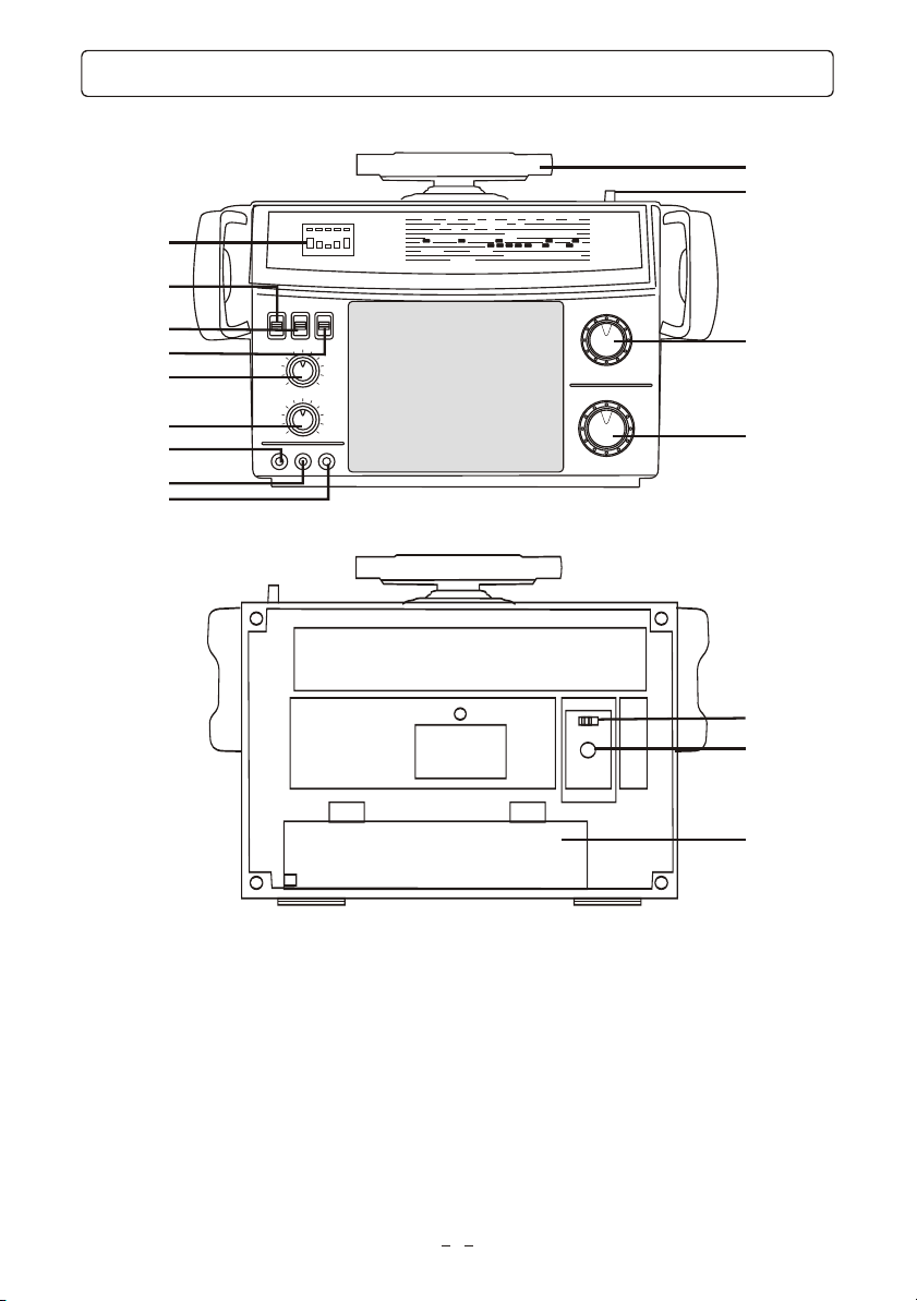
FUNCTIONS & CONTROL
1
2
BOARDCAST
500 600 700 800 1000 1200 1400 1700
AM
BAND
BOARDCAST
1
2
SOUND 1
SOUND 2
WAVE
CAST
BAND
1 14 23 32 40
4 4.2 5 6
88 90 92 94 96 100 104 108
2
3 64 5
145 150 170 175
WEATHER
7 8 9 10 11 12
10 11 12 13
798
100 115 125 145
CITIZEN
POWER
SHORT WAVE
SHORT WAVE
HIGH LO
FULL
LOW
FM
TV
5
TUNING BATTERY
TV
VHF
A R
WEATHER
6
MHz
CHANNEL
MHz
MHz
MHz
CHANNEL
CHANNEL
MHz
MHz
MHz
10
11
12
13
7
8
3
9
4
14
15
16
1.
Direction Finder (AM Antenna)
2.
Telescopic Antenna
Tuning Control
3.
Rotary Band Selector
4.
Tuning/Battery Indicator
5.
AFC On/Off Switch
6.
Radio/P.A. Switch
7.
Power On/Off Switch
8.
9.
Volume Control
10.
Tone Control
11.
Microphone Input Jack
12.
External Antenna Jack
13.
Earphones Jack
14.
AC/DC Switch
15.
DC 12V Jack
16.
Battery/AC Cord Compartment
4
Page 5

DESCRIPTION OF CONTROLS
1. Direction Finder (AM Antenna)
Rotate this finder to improve AM RECEPTION.
2. Telescopic Antenna
Extend this antenna for better reception.
3. Tuning Control
Turn this control to select the desired station or frequency.
4. Rotary Band Selector
The function of the rotary band selector is as follows:
AM:
SW1:
SW2:
TV1:
TV2:
FM:
Aircraft:
VHF
CB:
WB:
5. Tuning/Battery Indicator
The LED will light from right to left as signal strength increases. The extreme left LED position
indicates the best possible signal reception in all bands. Battery condition is read when the radio is
not receiving a signal. Extreme right LED indicates strong batteries. Extreme left LED reading
indicates batteries are weak.
6. AFC Switch
Set this switch to "ON" to enjoy drift-free FM listening.
7. Radio/P.A. Switch
Use this switch to choose between Radio and Public address system.
8. Power On/Off Switch
Turn Power On or Off with this switch.
9. Volume Control
Volume is controlled by rotating this control from the extreme left position to the extreme right position.
Make your volume adjustments slowly and gradually.
10. Tone Control
Turning to the MAX, the bass and treble have equal amounts. Turning to the MIN will reduce the treble.
11. Microphone Jack
Insert a microphone for Public Address System.
12. External Antenna Jack
An external antenna is used for best results in tuning in weak Short Wave signals. Connect the external
lead to the external antenna jack.
13. Earphone Jack
When the earphone is inserted into the earphone jack, the speaker will be automatically cut off.
14. AC/DC Switch
Switch between AC and DC to match the power supply used.
AC - House current.
DC - Batteries, or 12-volt car adapter.(Not Included)
15. DC 12V JACK
Attach this to a car cigar lighter with a car adapter when necessary. CAR ADAPTER: Use only 12-volt,
1 Amp DC supply, negative ground.
16. Battery/AC Cord Compartment
Put batteries for DC operation and storage of the AC cord.
Standard AM broadcast band; used to receive AM stations.
Shortwave band 1 - 4.0 to 6.0 MHz
Shortwave band 2 - 7.0 to 12.0 MHz
Audio portion of television broadcasts, channels 2 through 6.
Audio portion of television broadcasts, channels 7 through 13.
FM broadcast band; used to receive FM stations.
Aircraft band used to listen to airport control towers and nearby airplanes.
Public Service band, used to listen to Police, Fire, Civil Defence, Rail Road,
Taxis, Highway Trucks, Private Mobile Telephone, etc.
Full 40 Channel citizens band reception.
Continuous 24-HR reception of U.S. Weather Bureau broadcasts.
5
Page 6

POWER SUPPLY
1. AC Operation
The AC/DC switch (at the back of the unit) controls the power supply. Be sure AC/DC switch is
in the proper position. AC for household current; DC for battery and 12-Volt adapter current.
AC DC
AC/DC switch
DC 12V Jack
AC Cord
compartment
2. Battery Installation
Insert four D size batteries in the battery compartment. Be sure that the batteries are inserted
correctly to avoid damage to the unit. Always remove them when the unit will not be used for a
long period of time, as this will cause leakage and subsequent damage to your set. The Tuning/
Battery indicator will show the battery strength when the unit is turned on so batteries can be
replaced if necessary.
3. 12-Volt Car Adapter Operation: (Adapter Not Included)
Connect the adapter properly to a working 12-Volt cigar lighter receptacle and firmly insert the
adapter cord plug to the DC 12V Jack located on the back of the radio cabinet. Be sure AC/DC
switch is in at DC position.
CAR ADAPTER (Optional accessory): Use only 12-Volt, 1Amp DC supply, negative ground.
The cigarette lighter plug is equipped with a fuse to protect the radio. To replace this fuse
unscrew the top of the plug.
AC DC
USE ONLY DC 12-VOLT -
1 AMP CAR ADAPTER CORD
CAR ADAPTER(Not Included)
Battery
compartment
12-VOLT CAR
CIGAR LIGHTER
6
Page 7

BASIC RADIO OPERATIONS
1.
Switch the POWER to "ON".
Note:
Make sure that the power supply selector
switch on the back cabinet is set
correctly for either AC or DC coperation.
ON
POWER
2.
Switch to RADIO.
RADIO
OFF
P. A .
3. Select a BAND. 4. Tune to the desired station.
SW1/SW2 FM/AIR
CB
AM
BAND
TV2 VHF
WB
TV1
5. Adjust the Volume and Tone
TONE
VOLUME
MIN MAX
MIN MAX
Tuning
NOTE:
1.
When FM reception is weak, set the AFC switch to "ON" to obtain a clearer sound.
2.
For AM reception, the direction finder can be rotated to improve reception when necessary.
3.
Be sure to fully extend the telescopic antenna and rotate to a direction that gives the clearest
sound. When receiving strong or nearby stations it may be desirable to shorten the antenna to
prevent distorted sound.
7
Page 8

MIC, ANTENNA AND EAR FUNCTIONS
MICROPHONES
This radio can also be used as a Public
Address System:
1.
Simply insert the microphone into the
Microphone Input jack on the front.
MIC
2.
Select the P.A. function.
NOTE: Power switch must be at "ON" position.
3.
Adjust the volume to a desired level.
EXTERNAL ANTENNA Function
An external antenna is used for best results in
tuning in weak Short Wave signals.
Connect an External Antenna to the
Antenna jack.
ANT
RADIO
P. A .
VOLUME
MIN MAX
To avoid feedback (howling sound) during P.A. operation, keep the microphone as
Note:
far away from the speaker as possible.
FOR PRIVATE LISTENING
EAR
1.
Insert an earphone plug into the EAR jack.
2.
All sound will be diverted via the earphone and the speaker will turn off automatically.
3.
Adjust the volume by using the volume control.
CAUTION:
When using the earphones set the volume to a low level first. Then put on the
earphones and gradually increase the volume to a comfortable level.
8
Page 9

STRAP ASSEMBLY
AM
BOAR
DCAST
500
600
700
CITIZ
EN
POWE
R
HIGH
LO
LOW
FULL
TUNING
BATT
ERY
1. To assemble the strap on left side. 2. To assemble the strap on right side.
800
BAND
10
00
12
00
1400
1
SHORT WAVE
1
SHORT WAVE
2
FM
BOAR
DCAST
88
TV
SOUN
D 1
2
TV
SOUND 2
VHF
WAVE
145 150
A R
CAST
WEATHE
R
BAND
1700
14 23 32
MHz
40
4
4.2 5
90 92
1
WEATHER
CHA
6
NNE
L
MHz
7
8 9
10 11
12
94 96 100
MHz
104
108
3
MHz
4
5
6
7
CHA
8
NNE
9
L
10
11
12
13
70 1
CHA
75
NNE
L
MHz
100
11
5
125 1
45
MHz
MHz
4
1
3
BOARDCAST
500 600 700 800 1000 1200 1400 1700
HIGH LO
TUNING BATTERY
AM
BAND
1 14 23 32 40
CITIZEN
POWER
1
SHORT WAVE
4 4.2 5 6
2
SHORT WAVE
FULL
LOW
BOARDCAST
FM
88 90 92 94 96 100 104 108
2
SOUND 1
TV
SOUND 2
TV
WAVE
VHF
145 150 170 175
A R
CAST
WEATHER
BAND
WEATHER
7 8 9 10 11 12
3 64 5
798
100 115 125 145
10 11 12 13
MHz
CHANNEL
MHz
MHz
MHz
CHANNEL
CHANNEL
MHz
MHz
MHz
HIGH LO
HIGH LO
TUNING BATTERY
TUNING BATTERY
POWER
POWER
LOW
LOW
AM
AM
CITIZEN
CITIZEN
SHORT WAVE
SHORT WAVE
SHORT WAVE
SHORT WAVE
FULL
FULL
FM
FM
TV
TV
TV
TV
VHF
VHF
A R
A R
WEATHER
WEATHER
BOARDCAST
BOARDCAST
500 600 700 800 1000 1200 1400 1700
500 600 700 800 1000 1200 1400 1700
BAND
BAND
1 14 23 32 40
1 14 23 32 40
1
1
4 4.2 5 6
4 4.2 5 6
2
2
BOARDCAST
BOARDCAST
88 90 92 94 96 100 104 108
88 90 92 94 96 100 104 108
2
2
SOUND 1
SOUND 1
SOUND 2
SOUND 2
WAVE
WAVE
145 150 170 175
145 150 170 175
CAST
CAST
BAND
BAND
3 64 5
3 64 5
798
798
WEATHER
WEATHER
7 8 9 10 11 12
7 8 9 10 11 12
10 11 12 13
10 11 12 13
100 115 125 145
100 115 125 145
2
4
1
MHz
MHz
CHANNEL
CHANNEL
MHz
MHz
MHz
MHz
MHz
MHz
CHANNEL
CHANNEL
CHANNEL
CHANNEL
MHz
MHz
MHz
MHz
MHz
MHz
3
2
3. To shorten the strap for hand carrying. 4. To extend the strap for shoulder carrying.
4
1
2
BOARDCAST
500 600 700 800 1000 1200 1400 1700
AM
BAND
1 14 23 32 40
CITIZEN
POWER
1
SHORT WAVE
4 4.2 5 6
2
SHORT WAVE
HIGH LO
FULL
LOW
FM
TV
TV
VHF
TUNING BATTERY
A R
WEATHER
BOARDCAST
SOUND 1
SOUND 2
WAVE
CAST
BAND
88 90 92 94 96 100 104 108
2
3 64 5
145 150 170 175
WEATHER
7 8 9 10 11 12
798
100 115 125 145
10 11 12 13
4
MHz
CHANNEL
MHz
MHz
MHz
CHANNEL
CHANNEL
MHz
MHz
MHz
BOARDCAST
500 600 700 800 1000 1200 1400 1700
AM
BAND
1 14 23 32 40
CITIZEN
POWER
1
SHORT WAVE
4 4.2 5 6
2
SHORT WAVE
HIGH LO
FULL
LOW
FM
TV
TV
VHF
TUNING BATTERY
A R
WEATHER
7 8 9 10 11 12
BOARDCAST
88 90 92 94 96 100 104 108
2
3 64 5
SOUND 1
10 11 12 13
798
SOUND 2
WAVE
145 150 170 175
100 115 125 145
CAST
BAND
WEATHER
1
3
MHz
CHANNEL
MHz
MHz
MHz
CHANNEL
CHANNEL
MHz
MHz
MHz
2
3
9
Page 10

ROTARY BAND SELECTOR
To play the radio on a particular band rotate the selector knob which is located on the front of
the case to one of the six positions.
SW1/SW2 FM/AIR
CB
AM
BAND
TV2 VHF
WB
TV1
1. AM and FM Listening
When playing the radio on the AM band, it is not necessary to raise the TELESCOPIC ANTENNA
since there is a built-in antenna for reception. However, radios are sensitive to direction,
therefore reception may be improved by rotating the direction finder to different position. For
FM listening, it may be necessary to raise the TELESCOPIC ANTENNA for maximum performance.
Be sure that the radio is tuned precisely to the FM station desired, otherwise, a howling or
hissing noise may distort the sound. Put the AFC switch to "ON" position to enjoy drift-free FM
listening. Unsatisfactory reception even with the antenna radised, may mean that the batteries
should be replaced.
2. Air Band [AIR]
The Aircraft band allows you to hear conversations between nearby air planes and control
towers. Again, the TELESCOPIC ANTENNA should be fully extended, and tuning should be
done very slowly and carefully to pick up these signals. Since aircraft transmissions are not
continuous, there will be times when no signal is received on a given frequency.
3. Shortwave Bands [SW1, SW2]
To operate the radio on Shortwave (SW1 and SW2) bands, extends and rotate the TELESCOPIC
ANTENNA, and tuning should be done very slowly and carefully to pick up these signals. When
tuning to various frequencies, remember that very small movement of the Tuning Control result
in a relatively large frequency change.
Move the control slowly and cautiously to pick up all signals within the range of your radio. The
best time for listening to shortwave broadcasts is during the evening and night-time hours.
Foreign stations generally schedule their transmissions in this period.
Broadcasts from Australia and the South Pacific are often best in the early morning hours. The
quality of shortwave reception will vary according to the season of the year, prevailing weather
conditions, changes in the atmosphere, and the frequency to which you are listening. Fall and
winter are generally the best seasons for shortwave reception, especially for European and Far
East stations, while Australian and South Pacific stations are strongest in the spring. In any case,
interference and intrusive noise are to be expected with any shortwave reception. The radio is
equipped with a tone control to help eliminate these intrusive noises.
10
Page 11

4. Weather Band Operation
The ability to pull in clear signals will vary depending upon your location in relation to the
broadcast location. These signals are somewhat like television signals, in that when you are
40-60 miles from the broadcast point your signal is lessened considerably (Especially if there
are obstructions, like mountains, etc.)
5. Citizen Band
Your CB hand will allow you to hear full 40-channel communications. The versatility of your
new multi-band will give you full listening capabilities, including all the highway action. You can
now be aware of traffic and road conditions, you can hear what the truckers say and how they
say it, and you can plan your trips to avoid traffic tie-ups and make your long road trips more
enjoyable. CB reception is on a limited range basis, and some conditions that may limit range
of reception are as follows:
a.
Electrical interference. Power lines and some vehicle ignition system may cause temporary
interference with reception.
b.
Obstructions. Natural terrain such as mountains, hills, trees, or tall buildings.
c.
Weather conditions. Humidity and extreme temperatures.
d.
Atmospheric conditions. Change may cause a broadcast to "skip".
CB transmissions are not continuous and there are times when there will be no signal on the
CB frequencies. The telescopic antenna should be fully extended and rotated for best reception.
When used inside a vehicle, the telescopic antenna should be exposed to the outside.
No FCC license is required to operate the CB band on your radio.
6. Public Service
Unlike AM and FM broadcasts, the transmission is not continuous, and there are times when
there is no signal on a given frequency. These are functional broadcasts and are used only
when necessary for the exchange of information. A certain amount of patience will pay off in
much listening enjoyment. The Public Service band will enable you to hear conversations
between fire fighting calls, taxi, truck and other private mobile transmission. The telescopic
antenna should be fully extended, and tuning should be done very slowly and carefully to pick
up all the signals above.
7. Television Channel Bands 2-13
TV1 & TV2 permit you to hear the audio portion of your favorite TV news, daytime drama, talk
or game shows, on channels 2-13. Simply extend the telescopic antenna and tune to desired
channel.
Both high-frequency and shortwave reception are sensitive to interference from atmospheric
conditions and certain solar phenomena called "sun spots".
Fluorescent lighting fixtures and television sets may also affect reception. It is suggested that
these latter sources of interference either be turned off when using these bands or that the
radio be at least 12 to 25 feet away from them. In metal frame or reinforced concrete
buildings, the radio should be placed near a window.
11
Page 12

TROUBLE SHOOTING
If no signals can be received on the radio, check the unit by following the procedures described
below.
l. If battery operated, check the following:
1.
AC/DC switch set to "DC" POSITION.
2.
Batteries are correctly inserted, and fully charged.
ll. If house current is being used, check the following:
1.1.
AC/DC switch set to "AC" POSITION.
lll. If DC 12-Volt adapter operated, check the following:
1.
Cigar lighter adapter cord is properly connected to a working 12-Volt receptacle and firmly
inserted in the DC 12V Jack located on the back of the radio cabinet.
2.
AC/DC switch set to "DC" position.
lV. If the procedure described above have been checked and are correct, check the following:
1.
Power switch set to "ON" position.
2.
Radio/P.A. switch set to "Radio" position.
3.
VOLUME set to an audible level.
4.
SW & Air transmissions are not constant-set radio at desired band with volume control high
and wait for transmissions.
V. If all the procedures have been checked and there is still no signal:
1.
Send the unit to a qualified service center for repair.
TECHNICAL DATA
Frequency Range:
Mains Power Supply:
Battery Power supply:
Power Output:
Power Consumption:
Dimensions:
Weight:
Part No. : 21-2043
301-01
AM:
CB:
SW1:
SW2:
FM:
AIR:
TV1:
TV2:
VHF:
WB:
120V 60 Hz
6V DC, 4 "D" BATTERIES
1W
5W
15.0"(W) X 10.2"(H) X 6.1"(D)
5.6 POUNDS (without batteries)
530-1710kHz
26.965 - 27.405 MHz CHANNELS: 1 - 40
4.0 - 6.0 MHz
7.0 - 12.0 MHz
88 - 108 MHz
108 - 135 MHz
59.75 - 87.75 MHz CHANNELS: 2 - 6
176 - 218 MHz CHANNELS: 7 - 13
145 - 175 MHz
162.4 - 162.55 MHz
12
Printed in China
 Loading...