

Page 1
SYSTEM OVERVIEW
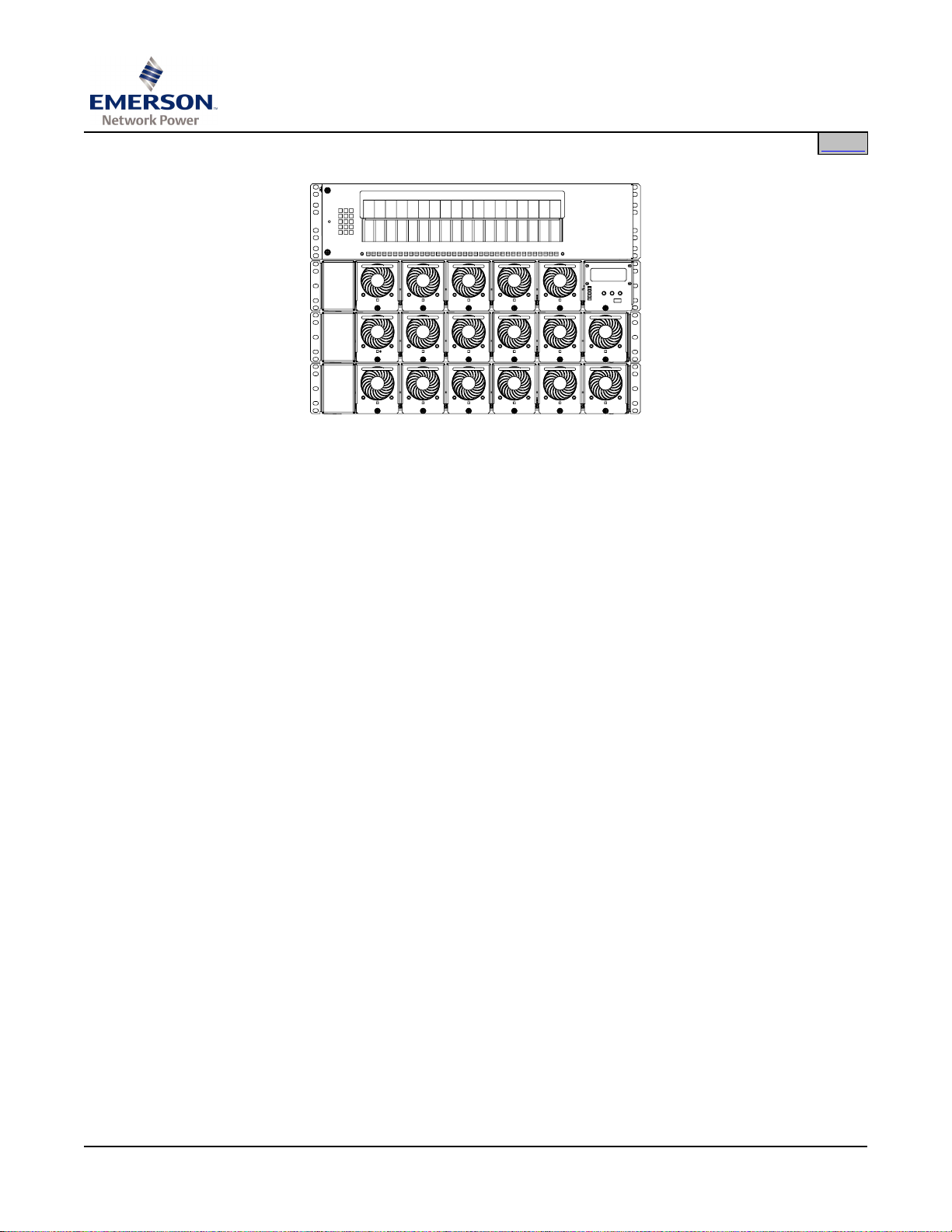
Description: -48VDC power system @ up to 555 Amperes, 25000 Watts max.
The Model LXP48F1 is a complete Power System containing power conversion,
intelligent monitoring and control, and distribution. An LXP Power System typically
consists of...
SAG582135000
System Application Guide
Spec. No. 582135000 (Model LXP48F1)
Issue AE, January 31, 2007
Home
• Distribution Cabinets
The system always includes a minimum of one Distribution Cabinet, which
provides DC distribution through fuses and/or circuit breakers.
A variety of distribution options are available that provide combinations of load
distribution, and Low Voltage Load or Battery Disconnect. Each Distribution
Cabinet accepts Bullet Nose-type circuit breakers and TPS/TLS-type fuse
holders.
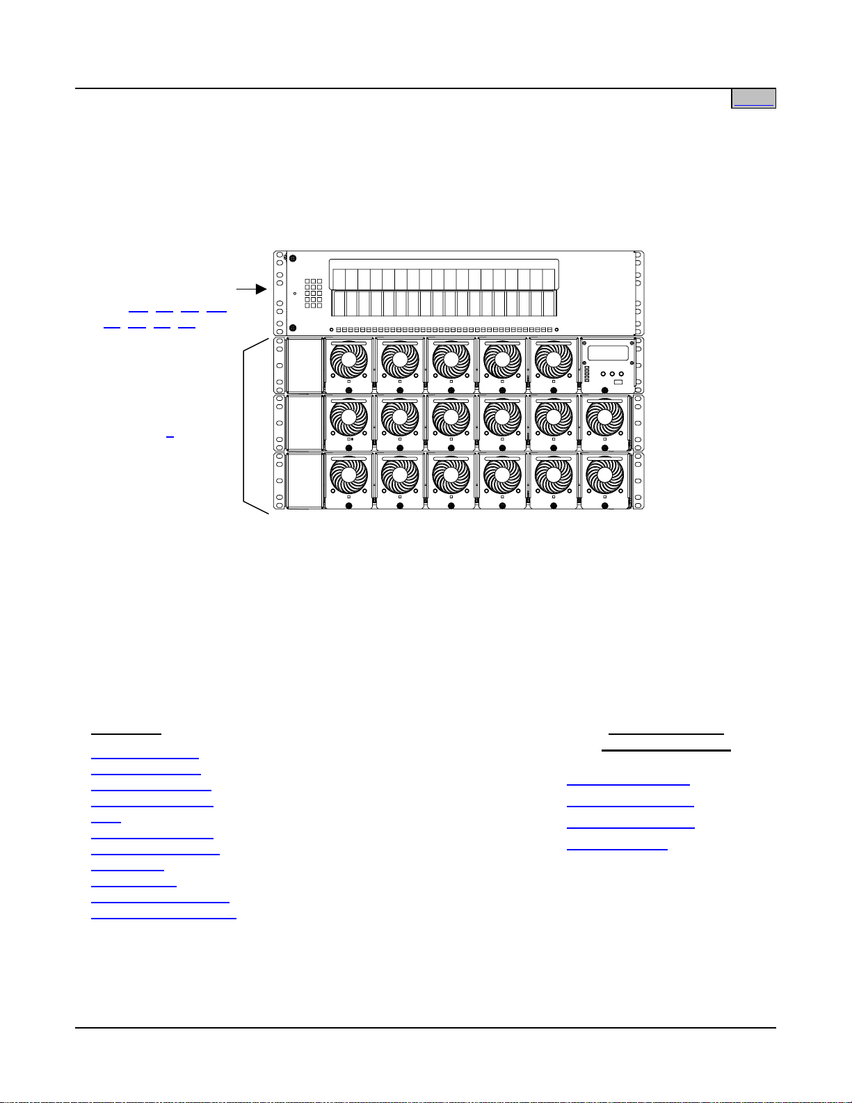
• Power Shelf
The system can include from one to three front access Power Shelves. The
Main Power Shelf houses the MCA and up to five (5) PCUs. Expansion Power
Shelves each house up to six (6) PCUs.
• MCA
Located in the Main Power Shelf, the Meter-Control-Alarm assembly (MCA)
controls the operation of all PCUs (17 max.) and provides system metering,
control, and alarm functions. The MCA features a Web Interface for
comprehensive remote monitoring and control capability.
• PCUs
Housed in the Power Shelves, the Power Conversion Units (PCUs) provide load
power, battery float current, and battery recharge current during normal operating
conditions.
Page 1 of 43
This document is property of Emerson Network Power, Energy Systems, North America, Inc. and contains confidential and proprietary information owned by Emerson Network Power, Energy
Systems, North America, Inc. Any copying, use, or disclosure of it without the written permission of Emerson Network Power, Energy Systems, North America, Inc. is strictly prohibited.
Page 2

SAG582135000 System Application Guide
Issue AE, January 31, 2007 Spec. No. 582135000 (Model LXP48F1)
Home
Family: LXP
Spec. No.: 582135000
Model: LXP48F1
Output Voltage: -48 Volts DC System
Output Capacity:
System (Three
Power Shelves): 555 Amperes, 25500 Watts max. (208/240V)
277.5 Amperes, 12750 Watts max. (120V)
Main Power Shelf: 163 Amperes, 7500 Watts max. (208/240V)
81.5 Amperes, 3750 Watts max. (120V)
Expansion Power Shelf: 196 Amperes, 9000 Watts max. (208/240V)
98 Amperes, 4500 Watts max. (120V)
PCU: 25A @ -58.0VDC to 32.6A @ -46VDC, 1500 Watts max. (208/240V)
12.5 @ -58.0VDC to 16.3A @ -46VDC, 750 Watts max. (120V)
Distribution Cabinet: Varies. See individual List Number.
Agency Approval: UL 1801 Listed (“c UL”)
Framework Type: Cabinets Designed for Relay Rack Mounting
Mounting Width: 23”
Mounting Depth: 12”
Front Projection: 5”
Access: Front and sides for installation; front for operation and maintenance
Control: Microprocessor
Color: Textured Cool Gray (M500-146)
Accessories: Circuit Breakers
, Fuses, GMT-Type Fuse Distribution Assembly,
Lugs, Relay Racks, Load Shed Card
Environment: +65°C (+149°F)
Page 2 of 43
This document is property of Emerson Network Power, Energy Systems, North America, Inc. and contains confidential and proprietary information owned by Emerson Network Power, Energy
Systems, North America, Inc. Any copying, use, or disclosure of it without the written permission of Emerson Network Power, Energy Systems, North America, Inc. is strictly prohibited.
Page 3
System Application Guide SAG582135000
Spec. No. 582135000 (Model LXP48F1) Issue AE, January 31, 2007
582135000
Distribution Cabinet
List BD, BL, BS, GA,
LB, LD, LS, LX
Power Shelf(s)
List 1
Home
SEE ALSO
System Overview
Table of Contents
List Structure Table
Distribution Devices
Lugs
Relay Rack Options
Replacement Cables
List of Parts
Specifications
Dimensional Drawings
Related Documentation
This document is property of Emerson Network Power, Energy Systems, North America, Inc. and contains confidential and proprietary information owned by Emerson Network Power, Energy
Systems, North America, Inc. Any copying, use, or disclosure of it without the written permission of Emerson Network Power, Energy Systems, North America, Inc. is strictly prohibited.
List 61: 1U Wireway
List 62: 2 U Wireway
List 93: Battery Tray
Load Shed Card
Page 3 of 43
OTHER OPTIONS
and ACCESSORIES
Page 4

SAG582135000 System Application Guide
Issue AE, January 31, 2007 Spec. No. 582135000 (Model LXP48F1)
TABLE OF CONTENTS
System
Overview
SYSTEM OVERVIEW................................................................................................................................................ 1
TABLE OF CONTENTS............................................................................................................................................ 4
LIST INFORMATION................................................................................................................................................. 6
Main List Numbers............................................................................................................................................... 6
Distribution List Numbers................................................................................................................................... 6
List Descriptions.................................................................................................................................................. 7
List 1: Model LXP9000SHF Integrated Power System ..................................................................................... 7
List 61: 1U Wireway .......................................................................................................................................... 7
List 62: 2U Wireway .......................................................................................................................................... 7
List 93: Battery Tray, Pre-cabled.......................................................................................................................8
List BD: Distribution Cabinet
List BL: Distribution Cabinet
List BS: Distribution Cabinet
List GA: Distribution Cabinet
List LB: Distribution Cabinet
List LD: Distribution Cabinet
List LS: Distribution Cabinet
List LX: Distribution Cabinet
Picture
(18) Fuse/Circuit Breaker Positions with
Low Voltage Battery Disconnect and Battery Shunt .......................................................................... 10
(18) Fuse/Circuit Breaker System Positions with
Low Voltage Battery Disconnect, Battery Shunt and Load Shunt...................................................... 11
(18) Fuse/Circuit Breaker System Positions with
Battery Shunt......................................................................................................................................12
(20) GMT Fuse System Positions with Split Bus................................................................................ 13
(18) Fuse/Circuit Breaker Positions with
Low Voltage Load Disconnect, Battery Shunt and Load Shunt.........................................................14
(18) Fuse/Circuit Breaker System Positions with
Low Voltage Load Disconnect and Load Shunt................................................................................. 15
(18) Fuse/Circuit Breaker System Positions with
Load Shunt......................................................................................................................................... 16
(18) Fuse/Circuit Breaker System Positions with
Battery Shunt and Load Shunt........................................................................................................... 17
List
Information
Accessory
Information
List of
Parts
Specifications
Physical Size
Information
Related
Documentation
ACCESSORY INFORMATION ............................................................................................................................... 18
Distribution Devices .......................................................................................................................................... 18
Bullet Nose Type Circuit Breakers ................................................................................................................... 18
TPS/TLS-Type Fuses....................................................................................................................................... 19
Plug-In GMT Fuse Distribution Assembly (Part No. 524679) (10) GMT Alarm-Type Fuse Positions ............. 20
Plug-In GMT Fuse Distribution Assembly (Part No. 528920) (6) GMT Alarm-Type Fuse Positions ............... 21
Alarm-Type Fuses............................................................................................................................................ 22
Recommended Wired Size and Lugs............................................................................................................... 23
Distribution (Load) Wire Sizes and Lugs—List BD, BL, BS, LB, LD, LS, LX ................................................... 23
Distribution (Load) Wire Sizes and Lugs—List GA .......................................................................................... 25
Battery Wire Sizes and Lugs—All Lists............................................................................................................ 25
DC Input Wire Sizes and Lugs—List GA..........................................................................................................26
Relay Rack Options........................................................................................................................................... 28
Transition Plates............................................................................................................................................... 28
Relay Rack Profiles.......................................................................................................................................... 29
Relay Rack Floor Mounting Dimensions.......................................................................................................... 30
Page 4 of 43
This document is property of Emerson Network Power, Energy Systems, North America, Inc. and contains confidential and proprietary information owned by Emerson Network Power, Energy
Systems, North America, Inc. Any copying, use, or disclosure of it without the written permission of Emerson Network Power, Energy Systems, North America, Inc. is strictly prohibited.
Page 5

System Application Guide SAG582135000
Spec. No. 582135000 (Model LXP48F1) Issue AE, January 31, 2007
Cables ................................................................................................................................................................. 31
RJ-45 MCA Control Bus Cable......................................................................................................................... 31
MCA Control Bus Interconnect Cable .............................................................................................................. 31
MCA Control Bus Termination Plug ................................................................................................................. 31
RJ-45 MCA Control Bus Termination Plug....................................................................................................... 31
Battery Temperature Probe............................................................................................................................... 32
Load Shed Card (Part No. 528927)................................................................................................................... 32
LIST OF PARTS...................................................................................................................................................... 33
SPECIFICATIONS................................................................................................................................................... 34
1.1 System Environmental Ratings............................................................................................................. 34
1.2 System Compliance Information........................................................................................................... 34
PHYSICAL SIZE INFORMATION........................................................................................................................... 35
Distribution Cabinet Dimensions—Lists BD, BL, BS, LB, LD, LS, LX.......................................................... 35
Distribution Cabinet Electrical Connection Locations and Dimensions— Lists BD, BL, BS, LB, LD, LS,
LX......................................................................................................................................................................... 36
Distribution Cabinet Dimensions—List GA..................................................................................................... 37
Distribution Cabinet Electrical Connection Locations and Dimensions— List GA.................................... 38
Wireway Dimensions—List 61 and 62 ............................................................................................................. 39
Dimensions of System Configured with List 93 Battery Trays..................................................................... 40
Overall Dimensions – Part No. 528927 Load Shed Card............................................................................... 41
RELATED DOCUMENTATION............................................................................................................................... 42
BATTERY MANUFACTURER INFORMATION ..................................................................................................... 42
REVISION RECORD............................................................................................................................................... 43
Page 5 of 43
This document is property of Emerson Network Power, Energy Systems, North America, Inc. and contains confidential and proprietary information owned by Emerson Network Power, Energy
Systems, North America, Inc. Any copying, use, or disclosure of it without the written permission of Emerson Network Power, Energy Systems, North America, Inc. is strictly prohibited.
Page 6
SAG582135000 System Application Guide
Issue AE, January 31, 2007 Spec. No. 582135000 (Model LXP48F1)
Home
LIST INFORMATION
(If viewed electronically, more detailed information is available for each option by clicking on t he desired number
in the column entitled List No. in the table below.)
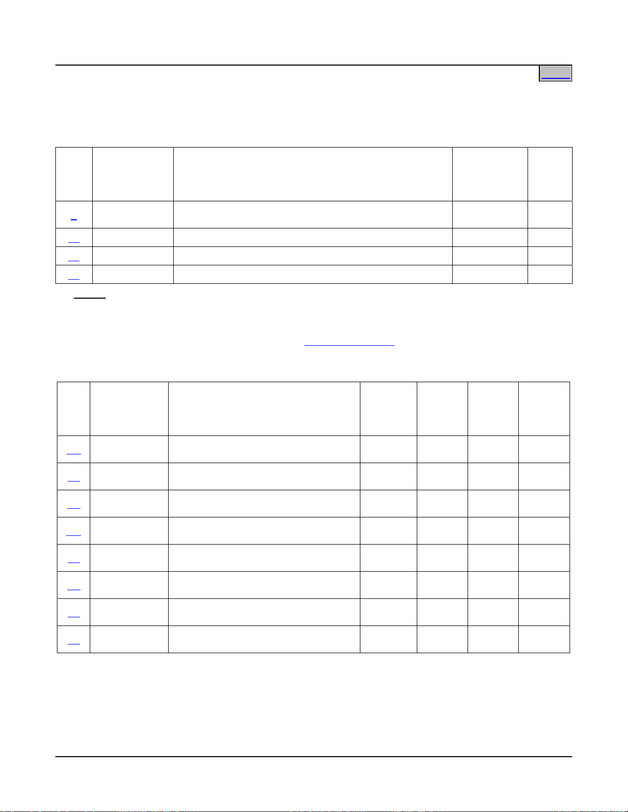
Main List Numbers
Mounting
List
No.
Part Number
DDeessccrriippttiioonn
1 58213500001 Model LXP9000SHF Integrated Power System
61 58213500061 Wireway, 19” x 1-3/4” 1 --
62 58213500062 Wireway, 19” x 3-1/2” 2 --
93 58213500093 Battery Tray, Pre-cabled As Requested --
Notes:
1) Order all List 1 components (Power Shelves, PCUs and MCA per System Application Guide
SAG589200100.
Positions
(1U =
1-3/4”)
2 per shelf,
6 max.
Notes
1, 2
2) Separately order relay racks as required. See Relay Rack Options
Distribution List Numbers
List
No.
BD 582135000BD
BL 582135000BL
BS 582135000BS
GA 582135000GA
LB 582135000LB
LD 582135000LD
LS 582135000LS
LX 582135000LX
Part Number
DDeessccrriippttiioonn
Distribution Cabinet: (18) Bullet Nose
Positions
Distribution Cabinet: (18) Bullet Nose
Positions
Distribution Cabinet: (18) Bullet Nose
Positions
Distribution Cabinet: (20) GMT Fuse
Positions, Split Bus
Distribution Cabinet: (18) Bullet Nose
Positions
Distribution Cabinet: (18) Bullet Nose
Positions
Distribution Cabinet: (18) Bullet Nose
Positions
Distribution Cabinet: (18) Bullet Nose
Positions
for available relay racks.
Mounting
Positions
(1U =
1-3/4”)
Single
or Dual
Voltage
Low
Voltage
Discon-
nect
Shunts
3 Single Battery Battery
3 Single Battery
Battery
& Load
3 Single None Battery
1 Single None None
3 Single Load
Battery
& Load
3 Single Load Load
3 Single None Load
3 Single None
Battery
& Load
Page 6 of 43
This document is property of Emerson Network Power, Energy Systems, North America, Inc. and contains confidential and proprietary information owned by Emerson Network Power, Energy
Systems, North America, Inc. Any copying, use, or disclosure of it without the written permission of Emerson Network Power, Energy Systems, North America, Inc. is strictly prohibited.
Page 7

System Application Guide SAG582135000
Spec. No. 582135000 (Model LXP48F1) Issue AE, January 31, 2007
Home
List Descriptions
List 1: Model LXP9000SHF Integrated Power System
Features
List of Parts
♦ Complete LXP Integrated Power System platform, provides Main Power Shelf, MCA, up to two Expansion
Power Shelves, and up to 17 PCUs.
♦ For more information, refer to System Application Guide SAG589200100.
Restrictions
♦ List 20 of 589200100 (Bulk Termination Panel) cannot be used when system is ordered with any of the
available distribution options (List BD, BL, BS, GA, LB, LD, LS, LX).
Ordering Notes
1) Order Power Shelves, PCUs and MCA, per SAG589200100.
2) If required, order relay rack per Table 6
3) Order Distribution Cabinets, as required, per Distribut ion List Numbers
4) Order load distribution fuses and/or circuit breakers, as required, per Tables 1
5) Order load distribution lugs, as required, per Table 4
6) Order battery lugs, as required, per Table 5
.
table.
, 2 and 3.
.
.
List 61: 1U Wireway
Features
List of Parts
♦ Designed to mount immediately above any 3U-high LXP Distribution Cabinet—provides protection for load,
battery, alarm and control cabling routed from top of Distribution Cabinet to rear of system.
♦ See Wireway Dimensions—List 61 and 62
under Physical Size Information.
List 62: 2U Wireway
Features
List of Parts
♦ Designed to mount immediately above any 3U-high LXP Distribution Cabinet—provides protection for load,
battery, alarm and control cabling routed from top of Distribution Cabinet to rear of system.
♦ See Wireway Dimensions—List 61 and 62
under Physical Size Information.
Page 7 of 43
This document is property of Emerson Network Power, Energy Systems, North America, Inc. and contains confidential and proprietary information owned by Emerson Network Power, Energy
Systems, North America, Inc. Any copying, use, or disclosure of it without the written permission of Emerson Network Power, Energy Systems, North America, Inc. is strictly prohibited.
Page 8
SAG582135000 System Application Guide
Issue AE, January 31, 2007 Spec. No. 582135000 (Model LXP48F1)
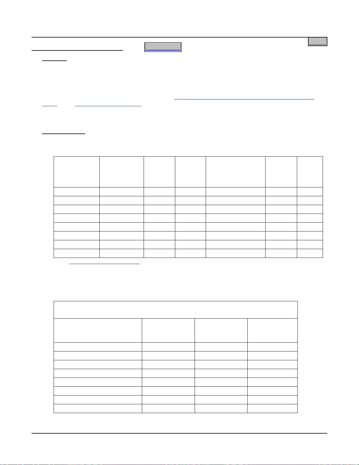
List 93: Battery Tray, Pre-cabled
Features
List of Parts
♦ Provides one battery tray that mounts four (4) 12V front terminal VLRA batteries. Batteries are configured as
one (1) 48V string. Battery cabling is factory-connected to Power System main bus.
♦ Accepts various Valve Regulated Lead Acid (VLRA) batteries. See Ordering Notes below.
♦ Tray dimensions are 21.3” wide X 22.4” deep. See Dimensions of System Configured with List 93 Battery
Trays under Physical Size Information for a typical battery tray arrangement.
♦ Trays can be ordered with or without Battery Disconnect circuit breakers. When circuit breakers are ordered,
one is provided in the –48V lead of each battery string (1 circuit breakers per tray).
Home
Ordering Notes
1) Order multiples of List 93 for more than one (1) battery tray. See Restrictions below.
2) Order batteries separately. The following table lists batteries recommended for use with List 93.
Manufacturer*
Model Emerson
Network
Power
Part No.
Rated
8-Hr.
Capacity
(Ah)
Dimension
W x L x H
(Inches)
Required
Tray
Spacing
Weight
(lbs)
GNB Marathon M12V125FT -- 125 4.90 x 22.00 x 11.15 7U 105
GNB Marathon M12V155FT 112795 155 4.90 x 22.00 x 11.15 7U 119
Northstar NSB110FT -- 110 4.92 x 22.05 x 8.94 7U 91.3
Northstar NSB170FT -- 167 4.92 x 22.05 x 12.60 8U 131
Deka Unigy I 12AVR-150ET 122018 150 4.90 x 22.00 x 11.75 7U 115
C&D FA 12-150F FA12150 150 4.92 x 21.97 x 12.70 8U 131
Douglas DGS12-150F 125453 150 4.90 x 22.00 x 12.70 8U 137
Douglas DGS12-170F -- 170.8 4.92 x 22.05 x 12.60 8U 129.6
* See Battery Manufacturer Information.
3) Specify the batteries you intend to use with each List 93 ordered. Lugs for battery connections vary
according to the batteries to be installed. Battery cables will be lugged as shown in the following table.
The table is provided for reference only.
Battery Lug Kit Part Numbers
(Kit provides two lugs for one tray.)
Battery
Specified
Ordered Without
Circuit Breaker
Ordered With
Circuit Breaker
125A or Higher
Ordered With
Circuit Breaker
100A or Lower
GNB Marathon M12V125FT 528235 528235 528234
GNB Marathon M12V155FT 528235 528235 528234
Northstar NSB110FT 528235 528235 528234
Northstar NSB170FT 528235 528235 528234
Deka Unigy I 12AVR-150ET 528235 528235 528234
C&D FA 12-150F 528235 528235 528234
Douglas DGS12-150F 528237 528237 528236
Douglas DGS12-170F 528235 528235 528234
Page 8 of 43
This document is property of Emerson Network Power, Energy Systems, North America, Inc. and contains confidential and proprietary information owned by Emerson Network Power, Energy
Systems, North America, Inc. Any copying, use, or disclosure of it without the written permission of Emerson Network Power, Energy Systems, North America, Inc. is strictly prohibited.
Page 9
System Application Guide SAG582135000
Spec. No. 582135000 (Model LXP48F1) Issue AE, January 31, 2007
4) Specify rack spacing of 7U (12.25”) or 8U (14”) between trays and above top tray as required for
battery clearance. See table above.
5) Specify with or without Battery Disconnect circuit breakers. Note: All List 93 trays in a bay will be
furnished with or without Battery Disconnect circuit breakers as specified for the first tray ordered.
6) If ordering List 93 with circuit breakers, order one (1) circuit breaker per List 93 from the following table.
Ampere
Rating
Electrical/Mechanical Trip
Part Number
1
(Black Handle) Electrical Trip2 (White Handle)
50 256694300 256694400
60 256694700 256694800
70 256695100 256695200
75 256695500 256695600
100 256695900 256696000
125 100765 100762
150 100763 100764
200 121810 121809
Circuit Breaker Alarm Operation:
1
Provides an alarm during an electrical or manual trip condition.
2
Provides an alarm during an electrical trip condition only.
7) If ordering List 93 with circuit breakers, specify breaker mounting on left side or right side of tray.
Home
Restrictions
Maximum number of List 93’s per bay is five (5).
A single List 93 must mount at bottom of bay. Multiple List 93’s must mount starting at bottom of bay and
working upward.
Page 9 of 43
This document is property of Emerson Network Power, Energy Systems, North America, Inc. and contains confidential and proprietary information owned by Emerson Network Power, Energy
Systems, North America, Inc. Any copying, use, or disclosure of it without the written permission of Emerson Network Power, Energy Systems, North America, Inc. is strictly prohibited.
Page 10

SAG582135000 System Application Guide
Issue AE, January 31, 2007 Spec. No. 582135000 (Model LXP48F1)
Home
List BD: Distribution Cabinet
(18) Fuse/Circuit Breaker Positions with
Low Voltage Battery Disconnect and Battery Shunt
List of Parts
Features
♦ Single Voltage Distribution (-48V)
♦ Maximum Capacity: Input: 500A max.
Total Distribution: 300A max.
Battery Recharge Current: 500A max. @ +50°C; 400A @ +65°C.
Battery Terminals as Remote Feed: 200A max.
♦ (18) Mounting Positions for Load Distribution Fuses or Circuit Breakers, or accepts Alarm-Type Fuse
Distribution Assembly (Kit P/N 524679).
♦ Accepts TPS/TLS-Type Fuses (3 to 100A) or Bullet Nose Type Circuit Breakers (1 to 100A)
Caution:
A circuit breaker or fuse with a rating greater than 75 amperes SHALL HAVE an empty
mounting position between it and any other overcurrent protective device.
Caution
: The maximum size circuit breaker or fuse used in ambient temperatures above +50°C
ambient shall be 40 amperes.
♦ Includes (1) Low Voltage Battery Disconnect Contactor (LVBD)
♦ Includes (1) Battery Shunt
♦ See Distribution Cabinet Electrical Connection Locations and Dimensions
Restrictions
.
The maximum number of Distribution Cabinets in a system is three (3). Each Distribution Cabinet must be
mounted immediately above a Power Shelf with zero (0) inches of rack space between units to accommodate
the furnished busbar links. Adequate vertical mounting space must be provided above each Distribution
Cabinet to accommodate distribution and battery cabling.
Unless otherwise specified fuses and/or circuit breakers are mounted from right to left, starting with the
highest capacity and working to the lowest capacity.
Maximum size of wire to be connected to a single fuseholder or circuit breaker position is 2 AWG.
Ordering Notes
1) Order circuit breakers, as required, per Table 1
2) Order fuses, as required, per Tables 2
.
.
3) Order one (1) Part No. 117201 fuseholder per fuse ordered in 2) above.
4) Order one (1) Part No. 524690 mounting kit per circuit breaker or fuseholder ordered in 1) or 3) above.
Kit includes bullet socket busbar and hardware for mounting load and return lugs for one distribution
position.
5) Order one (1) Load lug (one-hole, 1/4” bolt clearance hole) and one (1) Load Return lug (two-hole, 1/4”
bolt clearance holes on 5/8” centers) as required for each distribution position per Table 4
.
Page 10 of 43
This document is property of Emerson Network Power, Energy Systems, North America, Inc. and contains confidential and proprietary information owned by Emerson Network Power, Energy
Systems, North America, Inc. Any copying, use, or disclosure of it without the written permission of Emerson Network Power, Energy Systems, North America, Inc. is strictly prohibited.
Page 11

System Application Guide SAG582135000
Spec. No. 582135000 (Model LXP48F1) Issue AE, January 31, 2007
Home
List BL: Distribution Cabinet
(18) Fuse/Circuit Breaker System Positions with
Low Voltage Battery Disconnect, Battery Shunt and Load Shunt
List of Parts
Features
♦ Single Voltage Distribution (-48V)
♦ Maximum Capacity: Input: 500A max.
Total Distribution: 300A max.
Battery Recharge Current: 500A max. @ +50°C; 400A @ +65°C.
Battery Terminals as Remote Feed: 200A max.
♦ (18) Mounting Positions for Load Distribution Fuses or Circuit Breakers, or accepts Alarm-Type Fuse
Distribution Assembly (Kit P/N 524679).
♦ Accepts TPS/TLS-Type Fuses (3 to 100A) or Bullet Nose Type Circuit Breakers (1 to 100A)
Caution:
A circuit breaker or fuse with a rating greater than 75 amperes SHALL HAVE an empty
mounting position between it and any other overcurrent protective device.
Caution
: The maximum size circuit breaker or fuse used in ambient temperatures above +50°C
ambient shall be 40 amperes.
♦ Includes (1) Low Voltage Battery Disconnect Contactor
♦ Includes and (1) Load Shunt (total distribution load) and (1) Battery Shunt
♦ Busbars are provided for power connections between Distribution Cabinet and Power Shelf.
♦ See Distribution Cabinet Electrical Connection Locations and Dimensions
Restrictions
.
The maximum number of Distribution Cabinets in a system is three (3). Each Distribution Cabinet must be
mounted immediately above a Power Shelf with zero (0) inches of rack space between units to accommodate
the furnished busbar links. Adequate vertical mounting space must be provided above each Distribution
Cabinet to accommodate distribution and battery cabling.
Fuses and/or circuit breakers are to be mounted from right to left, starting with the highest capacity and
working to the lowest capacity.
Maximum size of wire to be connected to a single fuseholder or circuit breaker position is 2 AWG.
Ordering Notes
1) Order circuit breakers, as required, per Table 1
2) Order fuses, as required, per Tables 2
.
.
3) Order one (1) Part No. 117201 fuseholder per fuse ordered in 2) above.
4) Order one (1) Part No. 524690 mounting kit per circuit breaker or fuseholder ordered in 1) or 3) above.
Kit includes bullet socket busbar and hardware for mounting load and return lugs for one distribution
position.
5) Order one (1) Load lug (one-hole, 1/4” bolt clearance hole) and one (1) Load Return lug (two-hole, 1/4”
bolt clearance holes on 5/8” centers) as required for each distribution position per Table 4
.
Page 11 of 43
This document is property of Emerson Network Power, Energy Systems, North America, Inc. and contains confidential and proprietary information owned by Emerson Network Power, Energy
Systems, North America, Inc. Any copying, use, or disclosure of it without the written permission of Emerson Network Power, Energy Systems, North America, Inc. is strictly prohibited.
Page 12

SAG582135000 System Application Guide
Issue AE, January 31, 2007 Spec. No. 582135000 (Model LXP48F1)
Home
List BS: Distribution Cabinet
(18) Fuse/Circuit Breaker System Positions with
Battery Shunt
List of Parts
Features
♦ Single Voltage Distribution (-48V)
♦ Maximum Capacity: Input: 500A max.
Total Distribution: 300A max.
Battery Recharge Current: 500A max. @ +50°C; 400A @ +65°C.
Battery Terminals as Remote Feed: 200A max.
♦ (18) Mounting Positions for Load Distribution Fuses or Circuit Breakers, or accepts Alarm-Type Fuse
Distribution Assembly (Kit P/N 524679).
♦ Accepts TPS/TLS-Type Fuses (3 to 100A) or Bullet Nose Type Circuit Breakers (1 to 100A)
Caution:
A circuit breaker or fuse with a rating greater than 75 amperes SHALL HAVE an empty
mounting position between it and any other overcurrent protective device.
Caution
: The maximum size circuit breaker or fuse used in ambient temperatures above +50°C
ambient shall be 40 amperes.
♦ Includes (1) Battery Shunt
♦ See Distribution Cabinet Electrical Connection Locations and Dimensions
Restrictions
.
The maximum number of Distribution Cabinets in a system is three (3). Each Distribution Cabinet must be
mounted immediately above a Power Shelf with zero (0) inches of rack space between units to accommodate
the furnished busbar links. Adequate vertical mounting space must be provided above each Distribution
Cabinet to accommodate distribution and battery cabling. Fuses and/or circuit breakers are to be mounted
from right to left, starting with the highest capacity and working to the lowest capacity.
Maximum size of wire to be connected to a single fuseholder or circuit breaker position is 2 AWG.
Ordering Notes
1) Order circuit breakers, as required, per Table 1
2) Order fuses, as required, per Tables 2
.
.
3) Order one (1) Part No. 117201 fuseholder per fuse ordered in 2) above.
4) Order one (1) Part No. 524690 mounting kit per circuit breaker or fuseholder ordered in 1) or 3) above.
Kit includes bullet socket busbar and hardware for mounting load and return lugs for one distribution
position.
5) Order one (1) Load lug (one-hole, 1/4” bolt clearance hole) and one (1) Load Return lug (two-hole, 1/4”
bolt clearance holes on 5/8” centers) as required for each distribution position per Table 4
.
Page 12 of 43
This document is property of Emerson Network Power, Energy Systems, North America, Inc. and contains confidential and proprietary information owned by Emerson Network Power, Energy
Systems, North America, Inc. Any copying, use, or disclosure of it without the written permission of Emerson Network Power, Energy Systems, North America, Inc. is strictly prohibited.
Page 13

System Application Guide SAG582135000
Spec. No. 582135000 (Model LXP48F1) Issue AE, January 31, 2007
Home
List GA: Distribution Cabinet
(20) GMT Fuse System Positions with
List of Parts
Split Bus
Features
♦ Single Voltage Distribution (-48V)
♦ Maximum Capacity: Input: 163A @ +40°C; 155A @ 50°C; 110A @ +65°C.
Total Distribution: 30A per bus, 60A total @ +65°C
Battery Recharge Current: 163A @ +40°C; 155A @ 50°C; 110A @ +65°C.
Battery Terminals as Remote Feed: 103A @ +40°C; 95A @ 50°C; 50A @ +65°C.
♦ (20) Mounting Positions for Alarm-Type Load Distribution Fuses, (10) per bus.
♦ Accepts GMT-Type Fuses (1/4A to 15A).
♦ Includes (20) dummy fuses equipped with safety fuse covers.
♦ Provides local and external fuse alarm.
♦ See Distribution Cabinet Electrical Connection Locations and Dimensions
Restrictions
.
Maximum distribution fuse size: 15A
Maximum size wire each fuse position accepts is 14 AWG.
Input is cable-fed only.
Maximum size wire input terminals accept is (1) 2 AWG per polarity.
No load or battery shunts are provided.
Ordering Notes
1) Order fuses, as required, per Tables 3
.
Page 13 of 43
This document is property of Emerson Network Power, Energy Systems, North America, Inc. and contains confidential and proprietary information owned by Emerson Network Power, Energy
Systems, North America, Inc. Any copying, use, or disclosure of it without the written permission of Emerson Network Power, Energy Systems, North America, Inc. is strictly prohibited.
Page 14

SAG582135000 System Application Guide
Issue AE, January 31, 2007 Spec. No. 582135000 (Model LXP48F1)
Home
List LB: Distribution Cabinet
(18) Fuse/Circuit Breaker Positions with
Low Voltage Load Disconnect, Battery Shunt and Load Shunt
List of Parts
Features
♦ Single Voltage Distribution (-48V)
♦ Maximum Capacity:
♦ Maximum Capacity: Input: 500A max.
Total Distribution: 300A max.
Battery Recharge Current: 500A max. @ +50°C; 400A @ +65°C.
Battery Terminals as Remote Feed: 200A max.
♦ (18) Mounting Positions for Load Distribution Fuses or Circuit Breakers, or accepts Alarm-Type Fuse
Distribution Assembly (Kit P/N 524679).
♦ Accepts TPS/TLS-Type Fuses (3 to 100A) or Bullet Nose Type Circuit Breakers (1 to 100A)
Caution:
A circuit breaker or fuse with a rating greater than 75 amperes SHALL HAVE an empty
mounting position between it and any other overcurrent protective device.
Caution
: The maximum size circuit breaker or fuse used in ambient temperatures above +50°C
ambient shall be 40 amperes.
♦ Includes (1) Low Voltage Load Disconnect Contactor (LVLD)
♦ Includes and (1) Load Shunt (total distribution load) and (1) Battery Shunt
♦ See Distribution Cabinet Electrical Connection Locations and Dimensions
Restrictions
.
The maximum number of Distribution Cabinets in a system is three (3). Each Distribution Cabinet must be
mounted immediately above a Power Shelf with zero (0) inches of rack space between units to accommodate
the furnished busbar links. Adequate vertical mounting space must be provided above each Distribution
Cabinet to accommodate distribution and battery cabling.
Fuses and/or circuit breakers are to be mounted from right to left, starting with the highest capacity and
working to the lowest capacity.
Maximum size of wire to be connected to a single fuseholder or circuit breaker position is 2 AWG.
Ordering Notes
1) Order circuit breakers, as required, per Table 1
2) Order fuses, as required, per Tables 2
.
.
3) Order one (1) Part No. 117201 fuseholder per fuse ordered in 2) above.
4) Order one (1) Part No. 524690 mounting kit per circuit breaker or fuseholder ordered in 1) or 3) above.
Kit includes bullet socket busbar and hardware for mounting load and return lugs for one distribution
position.
5) Order one (1) Load lug (one-hole, 1/4” bolt clearance hole) and one (1) Load Return lug (two-hole, 1/4”
bolt clearance holes on 5/8” centers) as required for each distribution position per Table 4
.
Page 14 of 43
This document is property of Emerson Network Power, Energy Systems, North America, Inc. and contains confidential and proprietary information owned by Emerson Network Power, Energy
Systems, North America, Inc. Any copying, use, or disclosure of it without the written permission of Emerson Network Power, Energy Systems, North America, Inc. is strictly prohibited.
Page 15

System Application Guide SAG582135000
Spec. No. 582135000 (Model LXP48F1) Issue AE, January 31, 2007
Home
List LD: Distribution Cabinet
(18) Fuse/Circuit Breaker System Positions with
Low Voltage Load Disconnect and Load Shunt
List of Parts
Features
♦ Single Voltage Distribution (-48V)
♦ Maximum Capacity: Input: 500A max.
Total Distribution: 300A max.
Battery Recharge Current: 500A max. @ +50°C; 400A @ +65°C.
Battery Terminals as Remote Feed: 200A max.
♦ (18) Mounting Positions for Load Distribution Fuses or Circuit Breakers, or accepts Alarm-Type Fuse
Distribution Assembly (Kit P/N 524679).
♦ Accepts TPS/TLS-Type Fuses (3 to 100A) or Bullet Nose Type Circuit Breakers (1 to 100A)
Caution:
A circuit breaker or fuse with a rating greater than 75 amperes SHALL HAVE an empty
mounting position between it and any other overcurrent protective device.
Caution
: The maximum size circuit breaker or fuse used in ambient temperatures above +50°C
ambient shall be 40 amperes.
♦ Includes (1) Low Voltage Load Disconnect Contactor (LVLD)
♦ Includes and (1) Load Shunt (total distribution load)
♦ See Distribution Cabinet Electrical Connection Locations and Dimensions
Restrictions
.
The maximum number of Distribution Cabinets in a system is three (3). Each Distribution Cabinet must be
mounted immediately above a Power Shelf with zero (0) inches of rack space between units to accommodate
the furnished busbar links. Adequate vertical mounting space must be provided above each Distribution
Cabinet to accommodate distribution and battery cabling.
Fuses and/or circuit breakers are to be mounted from right to left, starting with the highest capacity and
working to the lowest capacity.
Maximum size of wire to be connected to a single fuseholder or circuit breaker position is 2 AWG.
Ordering Notes
1) Order circuit breakers, as required, per Table 1
2) Order fuses, as required, per Tables 2
.
.
3) Order one (1) Part No. 117201 fuseholder per fuse ordered in 2) above.
4) Order one (1) Part No. 524690 mounting kit per circuit breaker or fuseholder ordered in 1) or 3) above.
Kit includes bullet socket busbar and hardware for mounting load and return lugs for one distribution
position.
5) Order one (1) Load lug (one-hole, 1/4” bolt clearance hole) and one (1) Load Return lug (two-hole, 1/4”
bolt clearance holes on 5/8” centers) as required for each distribution position per Table 4
.
Page 15 of 43
This document is property of Emerson Network Power, Energy Systems, North America, Inc. and contains confidential and proprietary information owned by Emerson Network Power, Energy
Systems, North America, Inc. Any copying, use, or disclosure of it without the written permission of Emerson Network Power, Energy Systems, North America, Inc. is strictly prohibited.
Page 16

SAG582135000 System Application Guide
Issue AE, January 31, 2007 Spec. No. 582135000 (Model LXP48F1)
Home
List LS: Distribution Cabinet
(18) Fuse/Circuit Breaker System Positions with
Load Shunt
List of Parts
Features
♦ Single Voltage Distribution (-48V)
♦ Maximum Capacity: Input: 500A max.
Total Distribution: 300A max.
Battery Recharge Current: 500A max. @ +50°C; 400A @ +65°C.
Battery Terminals as Remote Feed: 200A max.
♦ (18) Mounting Positions for Load Distribution Fuses or Circuit Breakers, or accepts Alarm-Type Fuse
Distribution Assembly (Kit P/N 524679).
♦ Accepts TPS/TLS-Type Fuses (3 to 100A) or Bullet Nose Type Circuit Breakers (1 to 100A)
Caution:
A circuit breaker or fuse with a rating greater than 75 amperes SHALL HAVE an empty
mounting position between it and any other overcurrent protective device.
Caution
: The maximum size circuit breaker or fuse used in ambient temperatures above +50°C
ambient shall be 40 amperes.
♦ Includes and (1) Load Shunt (total distribution load)
♦ See Distribution Cabinet Electrical Connection Locations and Dimensions
Restrictions
.
The maximum number of Distribution Cabinets in a system is three (3). Each Distribution Cabinet must be
mounted immediately above a Power Shelf with zero (0) inches of rack space between units to accommodate
the furnished busbar links. Adequate vertical mounting space must be provided above each Distribution
Cabinet to accommodate distribution and battery cabling.
Fuses and/or circuit breakers are to be mounted from right to left, starting with the highest capacity and
working to the lowest capacity.
Maximum size of wire to be connected to a single fuseholder or circuit breaker position is 2 AWG.
Ordering Notes
1) Order circuit breakers, as required, per Table 1
2) Order fuses, as required, per Tables 2
.
.
3) Order one (1) Part No. 117201 fuseholder per fuse ordered in 2) above.
4) Order one (1) Part No. 524690 mounting kit per circuit breaker or fuseholder ordered in 1) or 3) above.
Kit includes bullet socket busbar and hardware for mounting load and return lugs for one distribution
position.
5) Order one (1) Load lug (one-hole, 1/4” bolt clearance hole) and one (1) Load Return lug (two-hole, 1/4”
bolt clearance holes on 5/8” centers) as required for each distribution position per Table 4
.
Page 16 of 43
This document is property of Emerson Network Power, Energy Systems, North America, Inc. and contains confidential and proprietary information owned by Emerson Network Power, Energy
Systems, North America, Inc. Any copying, use, or disclosure of it without the written permission of Emerson Network Power, Energy Systems, North America, Inc. is strictly prohibited.
Page 17

System Application Guide SAG582135000
Spec. No. 582135000 (Model LXP48F1) Issue AE, January 31, 2007
Home
List LX: Distribution Cabinet
(18) Fuse/Circuit Breaker System Positions with
Battery Shunt and Load Shunt
List of Parts
Features
♦ Single Voltage Distribution (-48V)
♦ Maximum Capacity: Input: 500A max.
Total Distribution: 300A max.
Battery Recharge Current: 500A max. @ +50°C; 400A @ +65°C.
Battery Terminals as Remote Feed: 200A max.
♦ (18) Mounting Positions for Load Distribution Fuses or Circuit Breakers, or accepts Alarm-Type Fuse
Distribution Assembly (Kit P/N 524679).
♦ Accepts TPS/TLS-Type Fuses (3 to 100A) or Bullet Nose Type Circuit Breakers (1 to 100A)
Caution:
A circuit breaker or fuse with a rating greater than 75 amperes SHALL HAVE an empty
mounting position between it and any other overcurrent protective device.
Caution
: The maximum size circuit breaker or fuse used in ambient temperatures above +50°C
ambient shall be 40 amperes.
♦ Includes and (1) Load Shunt (total distribution load) and (1) Battery Shunt
♦ See Distribution Cabinet Electrical Connection Locations and Dimensions
Restrictions
.
The maximum number of Distribution Cabinets in a system is three (3). Each Distribution Cabinet must be
mounted immediately above a Power Shelf with zero (0) inches of rack space between units to accommodate
the furnished busbar links. Adequate vertical mounting space must be provided above each Distribution
Cabinet to accommodate distribution and battery cabling.
Fuses and/or circuit breakers are to be mounted from right to left, starting with the highest capacity and
working to the lowest capacity.
Maximum size of wire to be connected to a single fuseholder or circuit breaker position is 2 AWG.
Ordering Notes
1) Order circuit breakers, as required, per Table 1
2) Order fuses, as required, per Tables 2
.
.
3) Order one (1) Part No. 117201 fuseholder per fuse ordered in 2) above.
4) Order one (1) Part No. 524690 mounting kit per circuit breaker or fuseholder ordered in 1) or 3) above.
Kit includes bullet socket busbar and hardware for mounting load and return lugs for one distribution
position.
5) Order one (1) Load lug (one-hole, 1/4” bolt clearance hole) and one (1) Load Return lug (two-hole, 1/4”
bolt clearance holes on 5/8” centers) as required for each distribution position per Table 4
.
Page 17 of 43
This document is property of Emerson Network Power, Energy Systems, North America, Inc. and contains confidential and proprietary information owned by Emerson Network Power, Energy
Systems, North America, Inc. Any copying, use, or disclosure of it without the written permission of Emerson Network Power, Energy Systems, North America, Inc. is strictly prohibited.
Page 18

SAG582135000 System Application Guide
Issue AE, January 31, 2007 Spec. No. 582135000 (Model LXP48F1)
HomeHome
ACCESSORY INFORMATION
Distribution Devices
Bullet Nose Type Circuit Breakers
Each circuit breaker plugs into a single mounting position.
Ordering Notes
1) Order circuit breakers per Table 1
.
Note: Load should not exceed 80% of device rating.
Caution:
A circuit breaker with a rating greater than 75 amperes SHALL HAVE an empty mounting
position between it and any other overcurrent protective device.
Caution:
The maximum size circuit breaker used in ambient temperatures above +50°C ambient
shall be 40 amperes.
2) Order one (1) Part No. 524690 mounting kit for each circuit breaker ordered.
3) For lug and wire size selection, refer to Table 4
.
BULLET NOSE TYPE CIRCUIT BREAKERS
AMPERE
RATING
PART NUMBER
Electrical/
Mechanical Trip
1
PART NUMBER
Electrical Trip
2
(White Handle)
(Black Handle)
1 101596 102272
3 101597 102273
5 101598 102274
10 101599 102275
15 101600 102276
20 101601 102277
25 101602 102278
30 101603 102279
35 101604 102280
40 101605 102281
45 121997 121998
50 101606 102282
60 101607 102283
70 101608 102284
75 101609 102285
80 121995 121996
100 101610 102286
Circuit Breaker Alarm Operation:
1
Provides an alarm during an electrical or manual trip condition.
2
Provides an alarm during an electrical trip condition only.
Unless otherwise specified, breakers are to be mounted from right to left
starting with the highest capacity and working to the lowest capacity.
Table 1
Page 18 of 43
This document is property of Emerson Network Power, Energy Systems, North America, Inc. and contains confidential and proprietary information owned by Emerson Network Power, Energy
Systems, North America, Inc. Any copying, use, or disclosure of it without the written permission of Emerson Network Power, Energy Systems, North America, Inc. is strictly prohibited.
Page 19

System Application Guide SAG582135000
Spec. No. 582135000 (Model LXP48F1) Issue AE, January 31, 2007
TPS/TLS-Type Fuses
A single fuseholder provides for installation of a 3 to 100 ampere Bussmann TPS-type or Littelfuse TLS-type
fuse. This fuseholder plugs into a single mounting position on the compatible distribution bus options
described in this document. This fuseholder provides a GMT-A alarm type fuse, which operates open to
provide an alarm indication if the distribution fuse opens.
Ordering Notes
1) Order fuses per Table 2
.
Note: Load should not exceed 80% of device rating.
Caution:
A fuse with a rating greater than 75 amperes SHALL HAVE an empty mounting position
between it and any other overcurrent protective device.
Caution:
The maximum size fuse used in ambient temperatures above +50°C ambient shall be 40
amperes.
2) Order one (1) Part No. 117201 TPS/TLS-type fuseholder for each fuse.
3) Order one (1) Part No. 524690 mounting kit for each fuseholder ordered.
4) For lug and wire size selection, refer to Table 4
.
TPS/TLS-TYPE FUSES
AMPERE RATING PART NUMBER
3 248230900
5 248231000
6 248231200
10 248231500
15 248231800
20 248232100
25 248232400
30 248232700
40 248233300
50 248233900
60 248234200
70 248234500
80 118413
90 118414
100 118415
TPS/TLS-Type Fuseholder* 117201
* Fuseholders are not furnished and must be ordered as required.
Order (1) Part No. 117201 for each fuse position required.
Fuseholder includes (1) alarm fuse (Bussmann GMT-A 18/100 amp;
Emerson Network Power 248610301) and (1) alarm fuse safety cover
(Emerson Network Power P/N 248898700).
Unless otherwise specified, fuses are to be mounted from right to left
starting with the highest capacity and working to the lowest capacity.
Table 2
Home
Page 19 of 43
This document is property of Emerson Network Power, Energy Systems, North America, Inc. and contains confidential and proprietary information owned by Emerson Network Power, Energy
Systems, North America, Inc. Any copying, use, or disclosure of it without the written permission of Emerson Network Power, Energy Systems, North America, Inc. is strictly prohibited.
Page 20

SAG582135000 System Application Guide
Issue AE, January 31, 2007 Spec. No. 582135000 (Model LXP48F1)
Plug-In GMT Fuse Distribution Assembly (Part No. 524679)
(10) GMT Alarm-Type Fuse Positions
Features
♦ Mounts in (5) distribution positions of any Distribution Cabinet.
♦ 30A Maximum Capacity
♦ Provides (10) Load Distribution Fuse Positions (0.25 to 15A GMT Alarm-Type Fuses)
♦ Screw clamp type terminals
♦ Includes 10 dummy fuses equipped with safety fuse covers.
Restrictions
When factory-ordered, assembly will be installed starting at left-hand side of panel, unless otherwise
specified.
Maximum size of wire to be connected to a single fuse position is 14 AWG.
Ordering Notes
1) Order Part No. 524679 Kit. Provides one Part No. 509128 alarm fuse distribution assembly, ground
return link, and hardware.
2) Order fuses, as required, per Table 3
.
TB1
F6
F7
F8
F9
F10
F11
F5
F2
F1
Mounting Position for First GMT
Assembly When Factory-Installed
F4
F3
F12
Part No. 509128
Page 20 of 43
This document is property of Emerson Network Power, Energy Systems, North America, Inc. and contains confidential and proprietary information owned by Emerson Network Power, Energy
Systems, North America, Inc. Any copying, use, or disclosure of it without the written permission of Emerson Network Power, Energy Systems, North America, Inc. is strictly prohibited.
Page 21

System Application Guide SAG582135000
Spec. No. 582135000 (Model LXP48F1) Issue AE, January 31, 2007
Plug-In GMT Fuse Distribution Assembly (Part No. 528920)
(6) GMT Alarm-Type Fuse Positions
Features
♦ Mounts in (2) bullet nose distribution positions.
♦ 30A Maximum Capacity.
♦ Provides (6) Load Distribution Fuse Positions (0.25 to 15A GMT Alarm-Type Fuses).
♦ Screw clamp type terminals.
♦ Includes (6) dummy fuses equipped with safety fuse covers.
Restrictions
When factory-ordered, assembly will be installed in the two left-most bullet nose positions, unless otherwise
specified.
Maximum size of wire to be connected to a single fuse position is 14 AWG.
Fuses are not included.
Ordering Notes
1) Order Part No. 528920. Provides one Part No. 528958 alarm fuse distribution assembly, ground return
link, and hardware.
2) Order fuses, as required, per Table 3
.
Home
Mounting Position for GMT
Assembly When Factory-Installed
Page 21 of 43
This document is property of Emerson Network Power, Energy Systems, North America, Inc. and contains confidential and proprietary information owned by Emerson Network Power, Energy
Systems, North America, Inc. Any copying, use, or disclosure of it without the written permission of Emerson Network Power, Energy Systems, North America, Inc. is strictly prohibited.
Page 22

SAG582135000 System Application Guide
Issue AE, January 31, 2007 Spec. No. 582135000 (Model LXP48F1)
Alarm-Type Fuses
Note: When used for power distribution, load should not exceed 80% of device rating.
BUSSMANN ALARM-TYPE FUSES
AMPERE RATING PART NUMBER
FUSE
COLOR
18/100 GMT-A 248610301 ---
1/4 248610200 VIOLET
1/2 248610300 RED
3/4 248610500 BROWN
1-1/3 248610700 WHITE
2 248610800 ORANGE
3 248610900 BLUE
5 248611000 GREEN
7-1/2 248611300 BLACK-WHITE
10 248611200 RED-WHITE
15 248611500 RED-BLUE
Fuse Safety Cover
(Replacement)
Dummy Fuse
(Replacement)
248898700 ---
248872600 ---
Home
Table 3
Page 22 of 43
This document is property of Emerson Network Power, Energy Systems, North America, Inc. and contains confidential and proprietary information owned by Emerson Network Power, Energy
Systems, North America, Inc. Any copying, use, or disclosure of it without the written permission of Emerson Network Power, Energy Systems, North America, Inc. is strictly prohibited.
Page 23

System Application Guide SAG582135000
Spec. No. 582135000 (Model LXP48F1) Issue AE, January 31, 2007
Home
Recommended Wired Size and Lugs
Distribution (Load) Wire Sizes and Lugs—List BD, BL, BS, LB, LD, LS, LX
Features
♦ In each Distribution Cabinet, lug-terminated load conductors are connected to the distribution fuseholde r or
circuit breaker mounting positions and the ground busbar. The distribution fuseholder or circuit breaker
mounting positions provide 1/4-20 threaded holes for installation of customer-provided one-hole lugs that
have 1/4 in. bolt clearance holes. The ground busbar provides 1/4-20 threaded holes for installation of
customer-provided two-hole lugs that have 1/4 in. bolt clearance holes on 5/8” centers. Factory provides lugmounting hardware for the distribution fuseholder or circuit breaker positions a nd distribution ground busbar.
♦ For lug mounting hole size and spacing dimensions, refer to Electrical Connection Locations and Dime nsions
under Physical Size Information in this document. Maximum size of wire to be connected to a single
fuseholder or circuit breaker position is 2 AWG.
Restrictions
All lugs for customer connections must be ordered separately.
Ordering Notes
1) The rating of the distribution device determines the wire size requirements. For wire size and lug
selection, refer to Table 4
.
2) For other available lugs and hardware, refer to drawings 031110100 through 031110300.
Page 23 of 43
This document is property of Emerson Network Power, Energy Systems, North America, Inc. and contains confidential and proprietary information owned by Emerson Network Power, Energy
Systems, North America, Inc. Any copying, use, or disclosure of it without the written permission of Emerson Network Power, Energy Systems, North America, Inc. is strictly prohibited.
Page 24

SAG582135000 System Application Guide
Issue AE, January 31, 2007 Spec. No. 582135000 (Model LXP48F1)
Fuse/Circuit
Breaker
Amperage
1, 3, 5,
6, 10A
15A
20A
25A
30A
35A
40A
45A
50A
60A
70A
75A
80A
90A
100A
Home
Recm 90°C Wire Size
(1)
14 AWG 12 AWG 10 AWG 8 AWG 6 AWG 4 AWG 2 AWG
(2)
Loop Length (feet)
(3, 4, 5)
37
24
58
(3, 4)
39
-- 29
-- -- 37
-- -- 31
-- -- -- 42
-- -- -- 37
-- -- -- 33
-- -- -- 29
(3, 4, 5)
93
(3, 4, 5)
62
(3, 4)
46
(3, 4, 5)
148
(3, 4, 5)
99
(3, 4, 5)
74
(3, 4,)
59
(3, 4)
49
(3, 4, 5)
(3, 4, 5)
157
(3, 4, 5)
118
(3, 4, 5)
94
(3, 4, 5)
78
(3, 4)
67
(3, 4)
59
(3, 4)
52
(3)
47
-- -- -- -- 39
-- -- -- -- -- 53
-- -- -- -- -- 50
-- -- -- -- -- 47
-- -- -- -- -- -- 66
-- -- -- -- -- -- 59
Recommended Crimp Lug
236
(6)
(3, 4, 5)
(3, 4, 5)
(3, 4, 5)
(3, 4, 5)
(3, 4, 5)
(3, 4, 5)
(3, 4, 5)
(3, 4)
(3, 4,)
(3, 4)
376
250
188
150
125
107
94
83
75
62
(3, 4, 5)
(3, 4, 5)
(3, 4, 5)
(3, 4, 5)
(3, 4, 5)
(3, 4, 5)
(3, 4, 5)
149
(3, 4)
132
(3, 4)
119
(3, 4)
99
(3, 4)
85
(3, 4)
79
(3)
74
597
398
298
239
199
170
(3, 4, 5)
(3, 4, 5)
(3, 4, 5)
(3, 4, 5)
(3, 4, 5)
(3, 4, 5)
(3, 4, 5)
(3, 4)
(3, 4)
(3, 4)
(3, 4)
(3, 4)
(3, 4)
(3, 4)
(3, 4)
Load Lug
(1-hole)
Return Lug
(2-hole)
245312200 245312400 245312400 245350400 245350600 245350700 245350800
245342300 245342300 245342300 245390200 245346700 245346800 245346900
Table 4
Recommended Distribution (Load) Wire Size and Lug Selection for
TLS/TPS Fuse and Bullet Nose-Type Circuit Breaker (Load and Load Return)
Notes to Tables 4:
1
Wire sizes are based on recommendations of the American National Standards Institute (ANSI) approved
National Fire Protection Association's (NFPA) National Electrical Code (NEC). Table 310-16 for wire rated
at 90°C conductor temperature operating in ambient temperatures of 40°C, 50°C, and 65°C was used. For
other operating ambient temperatures, refer to the NEC. For operation in countries where the NEC is not
recognized, follow applicable codes.
2
Recommended wire sizes are sufficient to restrict voltage drop to 1.0 volt or less at listed branch current for
the loop lengths shown. Loop length is the sum of the lengths of the positive and negative leads.
3
Wire Size / Loop Length Combination Calculated using 40°C Ambient Operating Temperature.
4
Wire Size / Loop Length Combination Calculated using 50°C Ambient Operating Temperature.
Page 24 of 43
This document is property of Emerson Network Power, Energy Systems, North America, Inc. and contains confidential and proprietary information owned by Emerson Network Power, Energy
Systems, North America, Inc. Any copying, use, or disclosure of it without the written permission of Emerson Network Power, Energy Systems, North America, Inc. is strictly prohibited.
Page 25

System Application Guide SAG582135000
Spec. No. 582135000 (Model LXP48F1) Issue AE, January 31, 2007
5
Wire Size / Loop Length Combination Calculated using 65°C Ambient Operating Temperature.
6
Load lugs are one-hole for 1/4" bolt clearance. Load Return lugs are two-hole for 1/4" bolt
Home
clearance on 5/8" centers. Refer to drawing 031110100 for lug crimping information.
Distribution (Load) Wire Sizes and Lugs—List GA
Features
♦ In each List GA Distribution Cabinet, Screw compression terminals are provided for connecting Load and
Load Return wiring. Maximum size of wire to be connected to a single position is 14 AWG.
Battery Wire Sizes and Lugs—All Lists
Features
List BD, BL, BS, LB, LD, LS, LX: In each Distribution Cabinet, lug-terminated battery conductors are
♦
connected to the battery terminals. Captive nuts, (1/4-20 on 5/8" centers) are provided for installation of
customer provided two-hole lugs.
List GA: In each Distribution Cabinet, lug-terminated battery conductors are connected to the battery
terminals. Captive nuts, (1/4-20 on 5/8" centers) are provided for installation of customer provided two-hole
lugs.
♦ For lug mounting hole size and spacing dimensions, refer to the illustration provided in the Physical Size
Information section.
Restrictions
All lugs for customer connections must be ordered separately.
Customer must supply lug-mounting hardware.
Ordering Notes
1) Battery wire size varies depending on load, therefore no specific information is provided for wire size.
Refer to Table 5
for recommended wire sizes and lugs at rated maximum Distribution Cabinet load.
When making connections, observe correct polarity.
2) For other available lugs and hardware, refer to drawings 031110100 through 031110300.
Page 25 of 43
This document is property of Emerson Network Power, Energy Systems, North America, Inc. and contains confidential and proprietary information owned by Emerson Network Power, Energy
Systems, North America, Inc. Any copying, use, or disclosure of it without the written permission of Emerson Network Power, Energy Systems, North America, Inc. is strictly prohibited.
Page 26

SAG582135000 System Application Guide
Issue AE, January 31, 2007 Spec. No. 582135000 (Model LXP48F1)
Home
Maximum
Current
(Amps)
Ambient
Operating
Temperature
Length (Ft)
(1)
1.0 Volt Drop
Loop
Loop
Length (Ft)
(2)
0.25 Volt Drop
Recm 90°C
Wire Size
(2)
Recommended
(1)
Crimp Lug
(3)
List BB, BD, BL, BS, LB, LD, LS, LX
500 40°C
500 50°C
37 9 (3) 4 AWG (3) 245346800
59 14 (3) 2 AWG (3) 245350800
37 9 (3) 4 AWG (3) 245346800
59 14 (3) 2 AWG (3) 245350800
400 65°C 59 14 (3) 2 AWG (3) 245350800
List GA
163 40°C 36 9 (1) 2 AWG (1) 245350800
155 50°C 38 9 (1) 2 AWG (1) 245350800
110 65°C 54 13 (1) 2 AWG (1) 245350800
Table 5
Recommended Battery Wire Size and Lug Selection
Notes to Tables 5:
1
Wire sizes are based on recommendations of the American National Standards Institute (ANSI) approved
National Fire Protection Association's (NFPA) National Electrical Code (NEC). Table 310-17 (Single-Insulated
Copper Conductors in Free Air) for wire rated at 90°C conductor temperature operating in am bient
temperatures of 40°C, 50°C and 65°C was used. For other operating ambient temperatures, refer to the
NEC. For operation in countries where the NEC is not recognized, follow applica ble codes.
2
Recommended wire sizes are sufficient to restrict voltage drop to the voltage shown in the column heading, or
less, at rated full load output current of the shelf for the loop lengths shown in this column. Loop length is the
sum of the lengths of the positive and negative leads.
3
Two-hole lug, 1/4" bolt clearance hole, 5/8" centers. Refer to drawing 031110100 for lug crimpi ng information.
DC Input Wire Sizes and Lugs—List GA
Features
♦ In the List GA Distribution Cabinet, lug-terminated battery conductors are connected to the battery terminals.
Captive nuts, (1/4-20 on 5/8" centers) are provided for installation of customer provided two-hole lugs.
♦ For lug mounting hole size and spacing dimensions, refer to the illustration provided in the Physical Size
Information section.
Restrictions
All lugs for customer connections must be ordered separately.
Customer must supply lug-mounting hardware.
Ordering Notes
1) Refer to Table 5
for recommended wire sizes and lugs at rated maximum Distribution Cabinet load.
When making connections, observe correct polarity.
2) For other available lugs and hardware, refer to drawings 031110100 through 031110300.
Page 26 of 43
This document is property of Emerson Network Power, Energy Systems, North America, Inc. and contains confidential and proprietary information owned by Emerson Network Power, Energy
Systems, North America, Inc. Any copying, use, or disclosure of it without the written permission of Emerson Network Power, Energy Systems, North America, Inc. is strictly prohibited.
Page 27

System Application Guide SAG582135000
Spec. No. 582135000 (Model LXP48F1) Issue AE, January 31, 2007
Maximum
Current
(Amps)
Ambient
Operating
Temperature
Length (Ft)
(1)
1.0 Volt Drop
Loop
Loop
Length (Ft)
(2)
0.25 Volt Drop
Recm 90°C
Wire Size
(2)
Recommended
(1)
Crimp Lug
(3)
163 40°C 36 9 (1) 2 AWG (1) 245350800
155 50°C 38 9 (1) 2 AWG (1) 245350800
110 65°C 54 13 (1) 2 AWG (1) 245350800
Table 5
Recommended Battery Wire Size and Lug Selection
Notes to Tables 5:
1
Wire sizes are based on recommendations of the American National Standards Institute (ANSI) approved
National Fire Protection Association's (NFPA) National Electrical Code (NEC). Table 310-17 (Single-Insulated
Copper Conductors in Free Air) for wire rated at 90°C conductor temperature operating in am bient
temperatures of 40°C, 50°C and 65°C was used. For other operating ambient temperatures, refer to the
NEC. For operation in countries where the NEC is not recognized, follow applica ble codes.
2
Recommended wire sizes are sufficient to restrict voltage drop to the voltage shown in the column heading, or
less, at rated full load output current of the shelf for the loop lengths shown in this column. Loop length is the
sum of the lengths of the positive and negative leads.
3
Two-hole lug, 1/4" bolt clearance hole, 5/8" centers. Refer to drawing 031110100 for lug crimpi ng information.
Page 27 of 43
This document is property of Emerson Network Power, Energy Systems, North America, Inc. and contains confidential and proprietary information owned by Emerson Network Power, Energy
Systems, North America, Inc. Any copying, use, or disclosure of it without the written permission of Emerson Network Power, Energy Systems, North America, Inc. is strictly prohibited.
Page 28

SAG582135000 System Application Guide
Issue AE, January 31, 2007 Spec. No. 582135000 (Model LXP48F1)
Home
Relay Rack Options
The Power System is factory mounted to the relay rack specified when ordered. The following relay racks are
available:
Part
Number
Size
Available
Mounting Positions
(1U = 1-3/4”)
525004 51-3/8”H x 23”W 28U Welded
524915 6’0”H x 23”W 38U Welded
524913 7’0”H x 23”W 45U Welded
525111 7’0”H x 23”W 45U
Bellcore Seismic Zone 4 requirements)
Seismic (complies with
524914 7’6”H x 23”W 48U Welded
534821 8’0”H x 23”W 51U Welded
Table 6
Transition Plates
Order Part No. 509819 for a Transition Plate Kit to mount relay racks above
battery modules with outside dimensions of 26.75" x 26.38", 35.75" x 26.38", or
42.50" x 26.38".
The kit consists of two plates with three hole patterns and hardware (3/8") to
mount the plates to the following relay racks: 525004. Hardware to mount the
plates to the battery module is customer provided.
Notes
TRANSITION
PLATES
Page 28 of 43
This document is property of Emerson Network Power, Energy Systems, North America, Inc. and contains confidential and proprietary information owned by Emerson Network Power, Energy
Systems, North America, Inc. Any copying, use, or disclosure of it without the written permission of Emerson Network Power, Energy Systems, North America, Inc. is strictly prohibited.
Page 29

System Application Guide SAG582135000
Spec. No. 582135000 (Model LXP48F1) Issue AE, January 31, 2007
Relay Rack Profiles
84"
45
40
35
30
25
20
15
10
5
1
524913
RELAY RACK
525111
RELAY RACK
51-3/8"
96"
Home
90"
28
25
20
15
10
5
1
51
50
45
525004
RELAY RACK
48
45
40
35
30
25
20
15
10
5
524914
RELAY RACK
72"
37
35
30
25
20
15
10
5
1
524915
RELAY RACK
40
35
30
25
20
15
10
5
1
534821
RELAY RACK
1
Page 29 of 43
This document is property of Emerson Network Power, Energy Systems, North America, Inc. and contains confidential and proprietary information owned by Emerson Network Power, Energy
Systems, North America, Inc. Any copying, use, or disclosure of it without the written permission of Emerson Network Power, Energy Systems, North America, Inc. is strictly prohibited.
Page 30

SAG582135000 System Application Guide
Issue AE, January 31, 2007 Spec. No. 582135000 (Model LXP48F1)
Relay Rack Floor Mounting Dimensions
Note: All dimensions are in inches.
24.375
2.437
3.750
20.125
17.500
0.812 Dia.
(8 Places)
15.000
12.531
1.234
2.562
15.000
9.875
Part Nos. 524913, 524914, 524915, 534821
24.750
1.125
22.500
1.00
2.00
2.00
5.00
2.00
2.00
1.00
Part No. 525004
Masked for Fram e Ground Lug
0.281 Dia. Holes on 0.625 Centers
(Top of Rack, 2 Places)
0.437 Dia.
(12 Places)
Masked for Frame Gr ou nd Lu g
0.281 Dia. Holes on 0.625 Centers
(Top of Rack, 2 Places)
25.000
2.437
3.750
20.125
17.500
0.812 Dia.
(8 Places)
15.031
12.531
9.875
Masked for Frame Ground Lug
0.281 Dia. Holes on 0.625 Centers
(Top of Rack, 1 Place)
1.250
2.578
Part No. 525111
Page 30 of 43
This document is property of Emerson Network Power, Energy Systems, North America, Inc. and contains confidential and proprietary information owned by Emerson Network Power, Energy
Systems, North America, Inc. Any copying, use, or disclosure of it without the written permission of Emerson Network Power, Energy Systems, North America, Inc. is strictly prohibited.
Page 31

System Application Guide SAG582135000
Spec. No. 582135000 (Model LXP48F1) Issue AE, January 31, 2007
Home
Cables
RJ-45 MCA Control Bus Cable
Features
♦ Category 5 Straight Through cable terminated at each end with an RJ-45 plug.
♦ Required for MCA control bus interconnections between Distributio n Cabinets, from a Distribution Cabinet to
a Load Shed Card, or between Load Shed Cards.
♦ Cable identification color is blue.
Restrictions
Maximum combined MCA control bus cable length must not exceed 125 feet.
Ordering Notes
1) Order the required length from the following table.
Length Part Number Length Part Number
5 inches 524409 2 feet 524410
6 inches 509070 3 feet 514639
10 inches 528520 4 feet 509900
15 inches 509071 25 feet 514640
MCA Control Bus Interconnect Cable
Features
♦ MCA control bus, Power Shelf-to-Power Shelf interconnect cable. Six-inch cable terminated at each end with
a “flat” plug. Connects to ports located on the each shelf’s right side panel.
♦ Cable identification color is blue.
♦ Cables are furnished with Power Shelves as required.
Ordering Notes
1) For a replacement cable, order P/N 521121
MCA Control Bus Termination Plug
Features
♦ “Flat” termination plug must be installed in any unused MCA control bus port in a Main or Expansion Power
Shelf.
♦ Two plugs are furnished with each List 1
Ordering Notes
Main Power Shelf ordered.
1) For a replacement plug, order P/N 524651.
RJ-45 MCA Control Bus Termination Plug
Features
♦ Plug must be installed in any unused RJ-45 MCA control bus port in a Distribution Cabinet DSM card or Load
Shed Card.
♦ One plug is furnished with each Distribution Cabinet and with each accessory Load Shed Card ordered.
Page 31 of 43
This document is property of Emerson Network Power, Energy Systems, North America, Inc. and contains confidential and proprietary information owned by Emerson Network Power, Energy
Systems, North America, Inc. Any copying, use, or disclosure of it without the written permission of Emerson Network Power, Energy Systems, North America, Inc. is strictly prohibited.
Page 32

SAG582135000 System Application Guide
Issue AE, January 31, 2007 Spec. No. 582135000 (Model LXP48F1)
Ordering Notes
Home
1) For a replacement plug, order P/N 524653.
Battery Temperature Probe
This system can be used with one or more Battery Temperature Probes. Probe must be mounted near or on the
battery to sense battery temperature. Probes connect the MCA and allows it to:
• Automatically increase or decrease system output voltage to maintain battery float current as battery
ambient temperature decreases or increases, respectively. Battery life can be extended whe n an
optimum charge voltage with respect to temperature is maintained.
• Issue alarms if battery temperature increases above or decreases below preset adjustable limits.
Each Distribution Cabinet provides connections up to four (4) Battery Temperature Probes. Refer to
SAG589200100 for probe specifications and ordering information.
Load Shed Card (Part No. 528927)
Features
♦ Provides eight (8) relays that can be individually configured as additional alarm relays or as
Low Voltage Disconnect control relays for reducing the system load (load shed). If
configured for load disconnect, control of the relays can be based upon either system
voltage or battery discharge elapsed time.
♦ Provides four (4) battery midpoint monitoring inputs.
♦ All functions are configured and controlled by the system MCA.
♦ External mounting.
♦ Includes one (1) 2 ft. MCA control bus cable (P/N 524410) and one (1) control bus
termination plug (P/N 524653).
♦ See Physical Size Information
for Load Shed Card dimensions.
♦ See Load Shed Card Installation and Operating Instructions (Section 5985) for complete specifications.
Restrictions
Load shed contactors are not included.
A system battery shunt is required for timed Load Shed.
MCA version 3.0 or newer is required.
Maximum number of Load Shed Cards supported by MCA is four (4).
Maximum combined MCA control bus cable length must not exceed 125 feet.
Ordering Notes
1) Where MCA control bus cable lengths other than the furnished 2 ft. cable are required, order per RJ-45 MCA
Control Bus Cable under Cables.
Page 32 of 43
This document is property of Emerson Network Power, Energy Systems, North America, Inc. and contains confidential and proprietary information owned by Emerson Network Power, Energy
Systems, North America, Inc. Any copying, use, or disclosure of it without the written permission of Emerson Network Power, Energy Systems, North America, Inc. is strictly prohibited.
Page 33

System Application Guide SAG582135000
Spec. No. 582135000 (Model LXP48F1) Issue AE, January 31, 2007
HomeHome
LIST OF PARTS
(This Stocklist may not list every component contained in each List.)
LIST
NUMBER
QTY. PART
NUMBER
DESCRIPTION
1 1 589200100 Integrated Power System without Distribution
61 1
1
1
62 1
1
1
93
1
1
BD 1
1
1
BL 1
1
1
BS 1
1
1
GA 2
1
2
LB 1
1
1
LD 1
1
1
LS 1
1
1
LX 1
1
1
528278
528279
244822500
528364
528365
244822500
525017
367236700
521030
521031
524711
521030
521031
524712
521030
521031
524713
528226
524920
110982
521030
521031
524714
521030
521031
524715
521030
521031
524716
521030
521031
524717
Wireway, 1U x 23” relay rack mounting
Cover, wireway, 1U x 23”
Bushing, snap, 0.625
Wireway, 2U x 23” relay rack mounting
Cover, wireway, 2U x 23”
Bushing, snap, 0.625
Battery Tray
Bracket, cable
Busbar, gnd
Busbar, batt
Assembly, distr, -48V, 23”
Busbar, gnd
Busbar, batt
Assembly, distr, -48V, 23”
Busbar, gnd
Busbar, batt
Assembly, distr, -48V, 23”
Adapter plate 19” –23”
Assembly, distr, -48V, 19”
Fuse, input curlim, CSB, 35A, 100KAIR@170VDC, part of P/N 524920
Busbar, gnd
Busbar, batt
Assembly, distr, -48V, 23”
Busbar, gnd
Busbar, batt
Assembly, distr, -48V, 23”
Busbar, gnd
Busbar, batt
Assembly, distr, -48V, 23”
Busbar, gnd
Busbar, batt
Assembly, distr, -48V, 23”
Page 33 of 43
This document is property of Emerson Network Power, Energy Systems, North America, Inc. and contains confidential and proprietary information owned by Emerson Network Power, Energy
Systems, North America, Inc. Any copying, use, or disclosure of it without the written permission of Emerson Network Power, Energy Systems, North America, Inc. is strictly prohibited.
Page 34

SAG582135000 System Application Guide
Issue AE, January 31, 2007 Spec. No. 582135000 (Model LXP48F1)
Home
Home
SPECIFICATIONS
Note: For all List 1 specifications, including Power Shelves, PCUs and MCA, refer to System Application
Guide SAG589200100. The SAG can be accessed via the CD (Electronic Documentation Package)
furnished with your system.
For all Part No. 528927 Load Shed Card specifications, refer to Section 5985. Section 5985 can be
accessed via the CD (Electronic Documentation Package) furnished with your system.
1.1 System Environmental Ratings
1.1.1 Operating Ambient Temperature Range: -40°C to +65°C (-40°F to +149°F).
1.1.2 Storage Ambient Temperature Range: -40°C to +85°C (-40°F to +185°F).
1.1.3 Humidity: This Power System is capable of operating in an ambient relative humidity range of
0% to 95%, non-condensing.
1.1.4 Altitude: The maximum operating ambient temperature should be derated by 10°C at an
elevation of 10,000 feet above sea level. For elevations between 3,000 feet and 10,000 feet,
derate the maximum operating ambient temperature linearly.
1.1.5 Mounting: Recommended minimum aisle space clearance is 2'6" for the front of the relay rack
and 2' for the rear of the relay rack.
1.2 System Compliance Information
1.2.1 Safety Compliance:
(A) This power board is UL Listed ("c UL") as a DC Power Distribution Center for
Communications Equipment.
(B) This unit meets the requirements of CSA 22.2, No. 225 and is tested and Certified by UL ("c
UL") as a Custom Built Power Distribution Center for Communications Equipment.
Page 34 of 43
This document is property of Emerson Network Power, Energy Systems, North America, Inc. and contains confidential and proprietary information owned by Emerson Network Power, Energy
Systems, North America, Inc. Any copying, use, or disclosure of it without the written permission of Emerson Network Power, Energy Systems, North America, Inc. is strictly prohibited.
Page 35

System Application Guide SAG582135000
Spec. No. 582135000 (Model LXP48F1) Issue AE, January 31, 2007
Home
PHYSICAL SIZE INFORMATION
Distribution Cabinet Dimensions—Lists BD, BL, BS, LB, LD, LS, LX
Note: For overall dimensions of List 1 Power Shelves, refer to SAG589200100.
NOTES :
All dimensions are in inches.
1.
2. Weight of Distribution
12.000
Cabinet with Circuit Breakers
(In Pounds):
Net: 33
Shipping:
TOP VIEW
See Mounting Angle Detail
21.380
22.250
23.000
FRONT VIEW
5.000
5.250
Finish :
3.
Shelf Body: Bright Zinc
Front Panel: Textured Warm
Gray (M500-146)
RIGHT SIDE VIEW
MOUNTING ANGLE DETAIL
0.234
0.250 x 0.375
SLOT
0.500
0.750
LEFT SIDE VIEW
0.500
1.250
0.500
0.750
0.500
0.234
Page 35 of 43
This document is property of Emerson Network Power, Energy Systems, North America, Inc. and contains confidential and proprietary information owned by Emerson Network Power, Energy
Systems, North America, Inc. Any copying, use, or disclosure of it without the written permission of Emerson Network Power, Energy Systems, North America, Inc. is strictly prohibited.
Page 36

SAG582135000 System Application Guide
Issue AE, January 31, 2007 Spec. No. 582135000 (Model LXP48F1)
Home
Distribution Cabinet Electrical Connection Locations and Dimensions—
Lists BD, BL, BS, LB, LD, LS, LX
Notes:
1. For electrical connection locations and dimensions of List 1 Power Shelves, refer to SAG589200100.
2. All dimensions are in inches.
3. Distribution and battery cabling to exit cabinet through top panel.
LOAD RETURN
CONNECTIONS
1/4-20 Captive Nut, 36 Places,
for 2-Hole Lugs on 5/8" Centers
(Factory Supplies Lug
Mounting Hardware)
0.765
Central Office Ground
(1/4-20 Captive Nut)
POS. (+) BATTERY
LUG LANDINGS
See Detail B
LOAD
CONNECTIONS
1/4-20 Threaded Hole,
18 Places, for 1-Hole Lugs
(Factory Supplies Lug
Mounting Hardware)
LEFT SIDE VIEW
NEG
POS
(-)
(+)
INPUT FROM
POWER SHELF
See Detail A
1/4-20 Captive Nut
2 Places Per Polarity
F18/
CB18
DETAIL A
LOAD FUSES or CIRCUIT BREAKERS
FRONT VIEW
(COVER REMOVED)
J10
MCA
Control
Bus
1/4-20 Captive Nut
1.406
RIGHT SIDE VIEW
6 Places
F1/
CB1
NEG. (-) BATTERY
LUG LANDINGS
See Detail B
DETAIL B
0.625
0.875
1.000
0.875
Page 36 of 43
This document is property of Emerson Network Power, Energy Systems, North America, Inc. and contains confidential and proprietary information owned by Emerson Network Power, Energy
Systems, North America, Inc. Any copying, use, or disclosure of it without the written permission of Emerson Network Power, Energy Systems, North America, Inc. is strictly prohibited.
Page 37

System Application Guide SAG582135000
Spec. No. 582135000 (Model LXP48F1) Issue AE, January 31, 2007
Distribution Cabinet Dimensions—List GA
NOTES :
All dimensions are in inches.
1.
2. Weight (In Pounds).
Net: 15
12.000
5.000
TOP VIEW
See Mounting Angle Detail
Shipping: 19
Finish :
3.
Body: Bright Zinc
Front Panel: Textured Cool
Gray (M500-146)
17.380
18.250
19.000
22.250
23.000
FRONT VIEW
LEFT SIDE VIEW
1.718
RIGHT SIDE VIEW
MOUNTING ANGLE DETAIL
0.234
1.250
0.234
0.251
0.734
0.703
0.251
0.250 x 0.375
SLOT
(2 PLACES)
(3) 0.281 DIA.
Page 37 of 43
This document is property of Emerson Network Power, Energy Systems, North America, Inc. and contains confidential and proprietary information owned by Emerson Network Power, Energy
Systems, North America, Inc. Any copying, use, or disclosure of it without the written permission of Emerson Network Power, Energy Systems, North America, Inc. is strictly prohibited.
Page 38

SAG582135000 System Application Guide
Issue AE, January 31, 2007 Spec. No. 582135000 (Model LXP48F1)
Distribution Cabinet Electrical Connection Locations and Dimensions—
List GA
ENTRANCE FOR INPUT
CABLING (SIDE OR BOTTOM)
LEFT SIDE VIEW
INPUT
See Detail A
Input Return (+)
DETAIL A
0.625
-48V Input (-)
TOP VIEW
(COVER
REMOVED)
1/4-20 X 0.625
Threaded Stud,
2 Places per Polarity
(Factory supplies lug
mounting hardware. For
standard flat & lock washers
torque to 84 In. Lbs.)
LOAD CONNECTION S
See Detail C on
following page.
1/4-20 X 0.625
Threaded Stud,
4 Places per Polarity
(Customer supplies lug
mounting hardware. For
standard flat & lock washers
torque to 84 In. Lbs.)
BATTERY & LOAD
WIRING EXIT
RIGHT SIDE VIEW
POS (+)
NEG (-)
BATTERY
See Detail B
DETAIL B
0.750
Note: All dimensions are in inches.
0.625
Cable Clamps for Load
Conductor Routing
FRONT VIEW
(COVER
Load Connections
Load Return Connections
REMOVED)
Fuse
Alarm
Lead
Page 38 of 43
This document is property of Emerson Network Power, Energy Systems, North America, Inc. and contains confidential and proprietary information owned by Emerson Network Power, Energy
Systems, North America, Inc. Any copying, use, or disclosure of it without the written permission of Emerson Network Power, Energy Systems, North America, Inc. is strictly prohibited.
Page 39

System Application Guide SAG582135000
Spec. No. 582135000 (Model LXP48F1) Issue AE, January 31, 2007
Home
Wireway Dimensions—List 61 and 62
NOTES :
1. All dimensions are in inches.
2. Weight (In Pounds):
List 61:
Net: 4
Shipping:
List 62:
Net:
Shipping:
Finish :
3.
Body: Bright Zinc
Front Panel:
LIST 61
Textured Warm
Gray (M500-146)
Alarm & Control
Wiring Entrance.
Bushing
I. D. = 0.375
TOP VIEW
LIST 61 & 62
See Mounting Angle Detail
21.380
22.250
23.000
FRONT VIEW
LIST 61
8.120
5.000
1.750
RIGHT SIDE VIEW
See Mounting Angle Detail
21.380
22.250
23.000
FRONT VIEW
LIST 62
MOUNTING ANGLE DETAIL
0.234
0.703
1.250
0.734
LIST 61
0.250 x 0.375
SLOT
(2 PLACES)
(3) 0.281 DIA.
3.500
RIGHT SIDE VIEW
LIST 62
MOUNTING ANGLE DETAIL
LIST 62
0.234
0.500
1.000
1.000
Alarm & Control
Wiring Entrance.
Bushing
I. D. = 0.375
0.250 x 0.375
SLOT
(5 PLACES)
0.500
0.234
0.251
0.251
0.234
Page 39 of 43
This document is property of Emerson Network Power, Energy Systems, North America, Inc. and contains confidential and proprietary information owned by Emerson Network Power, Energy
Systems, North America, Inc. Any copying, use, or disclosure of it without the written permission of Emerson Network Power, Energy Systems, North America, Inc. is strictly prohibited.
Page 40

SAG582135000 System Application Guide
Issue AE, January 31, 2007 Spec. No. 582135000 (Model LXP48F1)
Home
Dimensions of System Configured with List 93 Battery Trays
Notes:
1.
Three trays shown as example.
Max. available per rack: five.
2.
Dimensions are in inches.
3.
Net Weight Per Tray, Less Batteries:
With Circuit Breaker Option: 33 lbs.
Without Circuit Breaker Option: 29 lbs.
12.25 or 14.00
as ordered
12.25 or 14.00
as ordered
Optional Battery
Disconnect Circuit
Breakers. Shown on
Right Side. Available
on Either Side.
9.781
24.437
FRONT VIEW
RIGHT SIDE VIEW
Page 40 of 43
This document is property of Emerson Network Power, Energy Systems, North America, Inc. and contains confidential and proprietary information owned by Emerson Network Power, Energy
Systems, North America, Inc. Any copying, use, or disclosure of it without the written permission of Emerson Network Power, Energy Systems, North America, Inc. is strictly prohibited.
Page 41

System Application Guide SAG582135000
Spec. No. 582135000 (Model LXP48F1) Issue AE, January 31, 2007
Overall Dimensions – Part No. 528927 Load Shed Card
0.781
1.250
Top View
3.000
0.250 DIA.
(5 PLACES)
R 0.125
R 0.250
(2 PLACES)
1.000
1.000
1.000
1.000
1.000
1.000
DOWN
LOAD SHED
STATUS
2.187
J3
CAN INTERFACE J2
TB4
POWER
1 BAT
2 GND
3 RTN
CARD
TB2
PIN 12
K8
K7
K6
K5
TB1
PIN 12
K4
K3
K2
K1
NO
C
NC
NO
C
NC
NO
C
NC
NO
C
NC
NO
C
NC
NO
C
NC
NO
C
NC
NO
C
NC
UP
7.250
7.625
TB3
BATTERY MIDPOINT
MONITOR
0.625
1 2 3 4
0.375
Left Side View
Front View
Right Side View
NOTES
1. All Dimensions are in Inches
Unless Otherwise Specified
2. Finish: Bright Zinc
(Lorain Spec. M500-53)
3. Weight:
Net: 12.7 oz.
Shipping: 24 oz.
Page 41 of 43
This document is property of Emerson Network Power, Energy Systems, North America, Inc. and contains confidential and proprietary information owned by Emerson Network Power, Energy
Systems, North America, Inc. Any copying, use, or disclosure of it without the written permission of Emerson Network Power, Energy Systems, North America, Inc. is strictly prohibited.
Bottom View
Page 42

SAG582135000 System Application Guide
Issue AE, January 31, 2007 Spec. No. 582135000 (Model LXP48F1)
Home
RELATED DOCUMENTATION
System Application Guide: SAG589200100 (Model LXP9000SHF Integrated Power System, includes all
PCU & MCA specifications.)
Schematic Diagrams: SD582135000 (LXP Power System, Spec. No. 5821 35000)
SD589200100 (Model LXP9000SHF LXP Integrated Power System)
SD521036 (Distribution Cabinets)
Wiring Diagrams: T582135000 (LXP Power System, Spec. No. 582135000)
T589200100 (Model LXP9000SHF LXP Integrated Power System)
T521036 (Distribution Cabinets)
Color MCA Menu Tree: Section 5956
Instructions: Section 5960, Installation Instructions (LXP Power System, Spec. No. 582135000)
Section 5961, User Instructions (LXP Power System, Spec. No. 582135000
Section 5940 (Battery Temperature Concentrator Module, Part No. 521211)
Section 5985 (Load Shed Card, Part No. 528927)
Load and Battery Lug Detail Drawings: 031110100
031110200
031110300
BATTERY MANUFACTURER INFORMATION
Some equipment described in this System Application Guide is designed to accommodate batteries from
various manufacturers. The following are referenced in this document.
C&D: C&D Technologies, Inc., Powercom Div., 1400 Union Meeting Road, Blue Bell, PA 19422-0858
®
Deka
: East Penn Mfg. Co., Inc., Lyon Station, PA 19536-0147
Douglas
Marathon
Northstar: NorthStar Battery Co. LLC, 4000 Continental Way, Springfield, MO 65803
®
: Douglas Battery Mfg. Co., 500 Battery Dr., Winston-Salem, NC 27117-2159
TM
: GNB Industrial Power, a Division of Exide Technologies, Princeton, NJ 08543.
Page 42 of 43
This document is property of Emerson Network Power, Energy Systems, North America, Inc. and contains confidential and proprietary information owned by Emerson Network Power, Energy
Systems, North America, Inc. Any copying, use, or disclosure of it without the written permission of Emerson Network Power, Energy Systems, North America, Inc. is strictly prohibited.
Page 43

System Application Guide SAG582135000
E-Signed by John Kirkpatrick 1/31/2007 Using ApproveIt
1/31/2007
E-Signed by Emmett Garton 1/31/2007 using ApproveIt
1/31/2007
Spec. No. 582135000 (Model LXP48F1) Issue AE, January 31, 2007
REVISION RECORD
Change
Issue
AA LLP202685 New.
AB LLP205194
AC LLP205652
AD LLP206694
AE LLP207759 Added Part No. 534821 relay rack.
Number
(ECO)
Description of Change Date Approved
Added List 61, 62, GA. Revised max. number
of List 93. Added restriction to List 1.
3/10/06
3/11/06
1/27/06
1/27/06
J. Kirkpatrick
R. Trifiletti
J. Kirkpatrick
J. Jasko
Added Load Shed Card and RJ-45 MCA
control bus cables to Accessories. Added
SD582135100, T582135100 and Section 5985
to Related Documentation. Revised lug kit
5/1/06
5/1/06
J. Kirkpatrick
J. Jasko
ordering information in each distribution List
description.
Added Part No. 528920 to Accessories.
Added MCA version requirement to P/N
528927 Load Shed Card description.
10/19/07
10/19/07
J. Kirkpatrick
J. Jasko
Home
Emerson Network Power / 1122 F Street / Lorain, Ohio 44052-2293 / (440) 288-1122
In Canada:
Emerson Electric Canada Limited
122 Edward St. / St. Thomas, Ontario N5P 1Z2 / (519) 631-0780
In Mexico:
Productos Emerson Network Power de Mexico S.A. de C.V.
Apartado Postal 77001 / Mexico 10 D.F., MX 11200 / (525) 576-8277
This document is property of Emerson Network Power, Energy Systems, North America, Inc. and contains confidential and proprietary information owned by Emerson Network Power, Energy
Systems, North America, Inc. Any copying, use, or disclosure of it without the written permission of Emerson Network Power, Energy Systems, North America, Inc. is strictly prohibited.
Page 43 of 43
 Loading...