

Page 1
AC Power
HELPF4F3F2F1
EMERSON
™
Network Power
Liebert
®
Press any key back to main menu
Lieber t NX
081 kVA -3x3
12- 16- 2009
Single
12:22 : 14
Normal
STATUS
EMERSON
™
Network Power
SILENCE ON/OFF
Remote Monitor Panel
Liebert
NX
For Business-Critical Continuity™
Liebert® Remote Monitoring Panel
User Manual
™
Page 2

Page 3

TABLE OF CONTENTS
IMPORTANT SAFETY INSTRUCTIONS . . . . . . . . . . . . . . . . . . . . . . . . . . . . . . . . . . . . . . . . . . . . . . . . 1
SAVE THESE INSTRUCTIONS . . . . . . . . . . . . . . . . . . . . . . . . . . . . . . . . . . . . . . . . . . . . . . . . .1
INFORMATION FOR THE PROTECTION OF THE ENVIRONMENT . . . . . . . . . . . . . . . . . . . .1
1.0 INTRODUCTION . . . . . . . . . . . . . . . . . . . . . . . . . . . . . . . . . . . . . . . . . . . . . . . . . . . . . . . . . .2
2.0 INSTALLATION . . . . . . . . . . . . . . . . . . . . . . . . . . . . . . . . . . . . . . . . . . . . . . . . . . . . . . . . . .4
2.1 Preliminary checks. . . . . . . . . . . . . . . . . . . . . . . . . . . . . . . . . . . . . . . . . . . . . . . . . . . . . . . . . . . 4
2.2 Location. . . . . . . . . . . . . . . . . . . . . . . . . . . . . . . . . . . . . . . . . . . . . . . . . . . . . . . . . . . . . . . . . . . . 4
2.3 Power Supply . . . . . . . . . . . . . . . . . . . . . . . . . . . . . . . . . . . . . . . . . . . . . . . . . . . . . . . . . . . . . . . 4
2.4 Cable Specifications . . . . . . . . . . . . . . . . . . . . . . . . . . . . . . . . . . . . . . . . . . . . . . . . . . . . . . . . . . 4
2.5 Mounting the RMP on Drywall . . . . . . . . . . . . . . . . . . . . . . . . . . . . . . . . . . . . . . . . . . . . . . . . . 5
2.6 Electrical connections. . . . . . . . . . . . . . . . . . . . . . . . . . . . . . . . . . . . . . . . . . . . . . . . . . . . . . . . . 6
3.0 OPERATION . . . . . . . . . . . . . . . . . . . . . . . . . . . . . . . . . . . . . . . . . . . . . . . . . . . . . . . . . . . .8
3.1 Startup and Reset. . . . . . . . . . . . . . . . . . . . . . . . . . . . . . . . . . . . . . . . . . . . . . . . . . . . . . . . . . . . 8
3.2 LED Mimic Power Flow . . . . . . . . . . . . . . . . . . . . . . . . . . . . . . . . . . . . . . . . . . . . . . . . . . . . . . 11
3.3 Audible Alarms—Buzzer . . . . . . . . . . . . . . . . . . . . . . . . . . . . . . . . . . . . . . . . . . . . . . . . . . . . . 11
3.4 Direct Access Push Buttons—Keys . . . . . . . . . . . . . . . . . . . . . . . . . . . . . . . . . . . . . . . . . . . . . 12
3.5 LCD Monitor and Menu Keys . . . . . . . . . . . . . . . . . . . . . . . . . . . . . . . . . . . . . . . . . . . . . . . . . 12
3.6 Detailed Description of Menu Items . . . . . . . . . . . . . . . . . . . . . . . . . . . . . . . . . . . . . . . . . . . . 14
3.7 Status and Event Messages . . . . . . . . . . . . . . . . . . . . . . . . . . . . . . . . . . . . . . . . . . . . . . . . . . . 16
3.8 Prompt (Popup) Windows . . . . . . . . . . . . . . . . . . . . . . . . . . . . . . . . . . . . . . . . . . . . . . . . . . . . 20
3.9 Dynamic Energy Flow Chart and UPS Help Screen . . . . . . . . . . . . . . . . . . . . . . . . . . . . . . . 20
3.10 Default screen saver. . . . . . . . . . . . . . . . . . . . . . . . . . . . . . . . . . . . . . . . . . . . . . . . . . . . . . . . . 21
4.0 TECHNICAL SPECIFICATIONS . . . . . . . . . . . . . . . . . . . . . . . . . . . . . . . . . . . . . . . . . . . . . . .22
4.1 Agency and Certifications . . . . . . . . . . . . . . . . . . . . . . . . . . . . . . . . . . . . . . . . . . . . . . . . . . . . 23
i
Page 4

FIGURES
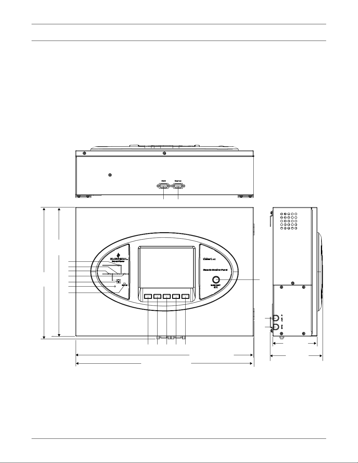
Figure 1 Remote Monitoring Panel components and functions. . . . . . . . . . . . . . . . . . . . . . . . . . . . . . . . . . . . 2
Figure 2 Remote Monitoring Panel layout constraints . . . . . . . . . . . . . . . . . . . . . . . . . . . . . . . . . . . . . . . . . . 3
Figure 3 RMP electrical input plug . . . . . . . . . . . . . . . . . . . . . . . . . . . . . . . . . . . . . . . . . . . . . . . . . . . . . . . . . . 4
Figure 4 Communication cable connection. . . . . . . . . . . . . . . . . . . . . . . . . . . . . . . . . . . . . . . . . . . . . . . . . . . . 5
Figure 5 Mounting hole dimensions . . . . . . . . . . . . . . . . . . . . . . . . . . . . . . . . . . . . . . . . . . . . . . . . . . . . . . . . . 5
Figure 6 Power and communication cable routing . . . . . . . . . . . . . . . . . . . . . . . . . . . . . . . . . . . . . . . . . . . . . . 6
Figure 7 RS-485 cable connection to Liebert NX . . . . . . . . . . . . . . . . . . . . . . . . . . . . . . . . . . . . . . . . . . . . . . . 7
Figure 8 Opening screen . . . . . . . . . . . . . . . . . . . . . . . . . . . . . . . . . . . . . . . . . . . . . . . . . . . . . . . . . . . . . . . . . . 8
Figure 9 Data loading progress screen . . . . . . . . . . . . . . . . . . . . . . . . . . . . . . . . . . . . . . . . . . . . . . . . . . . . . . . 8
Figure 10 UPS and RMP firmware are compatible screen . . . . . . . . . . . . . . . . . . . . . . . . . . . . . . . . . . . . . . . . 9
Figure 11 Silence On/Off screens . . . . . . . . . . . . . . . . . . . . . . . . . . . . . . . . . . . . . . . . . . . . . . . . . . . . . . . . . . . . 9
Figure 12 Communication with UPS failed . . . . . . . . . . . . . . . . . . . . . . . . . . . . . . . . . . . . . . . . . . . . . . . . . . . 10
Figure 13 Firmware not compatible with UPS screen . . . . . . . . . . . . . . . . . . . . . . . . . . . . . . . . . . . . . . . . . . . 10
Figure 14 Graphic LCD monitor windows and keypad . . . . . . . . . . . . . . . . . . . . . . . . . . . . . . . . . . . . . . . . . . 12
Figure 15 Menu tree . . . . . . . . . . . . . . . . . . . . . . . . . . . . . . . . . . . . . . . . . . . . . . . . . . . . . . . . . . . . . . . . . . . . . 13
Figure 16 Help screen . . . . . . . . . . . . . . . . . . . . . . . . . . . . . . . . . . . . . . . . . . . . . . . . . . . . . . . . . . . . . . . . . . . . 21
Figure 17 Default screen . . . . . . . . . . . . . . . . . . . . . . . . . . . . . . . . . . . . . . . . . . . . . . . . . . . . . . . . . . . . . . . . . . 21
TABLES
Table 1 RMP component location in Figure 1 . . . . . . . . . . . . . . . . . . . . . . . . . . . . . . . . . . . . . . . . . . . . . . . . 3
Table 2 Communication cable specifications . . . . . . . . . . . . . . . . . . . . . . . . . . . . . . . . . . . . . . . . . . . . . . . . . 4
Table 3 Rectifier indicator . . . . . . . . . . . . . . . . . . . . . . . . . . . . . . . . . . . . . . . . . . . . . . . . . . . . . . . . . . . . . . . 11
Table 4 Battery indicator . . . . . . . . . . . . . . . . . . . . . . . . . . . . . . . . . . . . . . . . . . . . . . . . . . . . . . . . . . . . . . . . 11
Table 5 Bypass indicator . . . . . . . . . . . . . . . . . . . . . . . . . . . . . . . . . . . . . . . . . . . . . . . . . . . . . . . . . . . . . . . . 11
Table 6 Inverter indicator . . . . . . . . . . . . . . . . . . . . . . . . . . . . . . . . . . . . . . . . . . . . . . . . . . . . . . . . . . . . . . . 11
Table 7 Load indicator . . . . . . . . . . . . . . . . . . . . . . . . . . . . . . . . . . . . . . . . . . . . . . . . . . . . . . . . . . . . . . . . . . 11
Table 8 Status (Alarm) indicator . . . . . . . . . . . . . . . . . . . . . . . . . . . . . . . . . . . . . . . . . . . . . . . . . . . . . . . . . . 11
Table 9 Audible alarm key . . . . . . . . . . . . . . . . . . . . . . . . . . . . . . . . . . . . . . . . . . . . . . . . . . . . . . . . . . . . . . . 11
Table 10 Menu key Icons and their meaning . . . . . . . . . . . . . . . . . . . . . . . . . . . . . . . . . . . . . . . . . . . . . . . . . 12
Table 11 UPS system window . . . . . . . . . . . . . . . . . . . . . . . . . . . . . . . . . . . . . . . . . . . . . . . . . . . . . . . . . . . . . 14
Table 12 Descriptions of RMP menus and data window items . . . . . . . . . . . . . . . . . . . . . . . . . . . . . . . . . . . 14
Table 13 RMP messages. . . . . . . . . . . . . . . . . . . . . . . . . . . . . . . . . . . . . . . . . . . . . . . . . . . . . . . . . . . . . . . . . . 16
Table 14 Prompt windows, meanings controlled at UPS only. . . . . . . . . . . . . . . . . . . . . . . . . . . . . . . . . . . . 20
Table 15 Prompt windows, meanings controlled at RMP . . . . . . . . . . . . . . . . . . . . . . . . . . . . . . . . . . . . . . . 20
Table 16 Mechanical specifications . . . . . . . . . . . . . . . . . . . . . . . . . . . . . . . . . . . . . . . . . . . . . . . . . . . . . . . . . 22
Table 17 Environmental specifications . . . . . . . . . . . . . . . . . . . . . . . . . . . . . . . . . . . . . . . . . . . . . . . . . . . . . . 22
Table 18 Electrical specifications . . . . . . . . . . . . . . . . . . . . . . . . . . . . . . . . . . . . . . . . . . . . . . . . . . . . . . . . . . 22
Table 19 Cable specifications. . . . . . . . . . . . . . . . . . . . . . . . . . . . . . . . . . . . . . . . . . . . . . . . . . . . . . . . . . . . . . 22
Table 20 Electromagnetic interference (EMI)—emission limits . . . . . . . . . . . . . . . . . . . . . . . . . . . . . . . . . . 23
Table 21 Electromagnetic susceptibility (EMS)—immunity levels . . . . . . . . . . . . . . . . . . . . . . . . . . . . . . . . 23
ii
Page 5

IMPORTANT SAFETY INSTRUCTIONS
SAVE THESE INSTRUCTIONS
This manual contains important safety and operating instructions concerning the installation and
operation of the Liebert NX Remote Monitoring Panel (RMP). Read all safety, installation and operating instructions before beginning installation. Adhere to all warnings on the unit and in this manual.
Follow all operating and user instructions.
The Liebert NX Remote Monitoring Panel must be commissioned and serviced by an engineer
approved by Liebert. Failure to do so may result in personnel safety risk, equipment malfunction and
invalidation of warranty.
The Remote Monitoring Panel is designed and intended for commercial and industrial use. It is not
recommended for use in life-support applications.
ELECTROMAGNETIC COMPATIBILITY—This is a low-emission, Class A product. Operating
this device in a residential area is likely to cause harmful interference that users must correct at their
own expense. Pursuant to FCC regulations, operation is subject to the following two conditions:
1. This device may not cause harmful interference; and
2. This device must accept any interference received, including interference that may cause
undesired operation.
Conformity and Standards
This equipment complies with CE directives 73/23 & 93/68 (LV Safety) and 89/336 (EMC), with Australia and New Zealand EMC Framework (C-Tick) and with the following product standards for Uninterruptible Power System (UPS).
• EN / IEC / AS 62040-1-1-General and safety requirements for use in operator access area
• EN / IEC / AS 62040-2-EMC requirements; Class A compliant
• EN / IEC / AS 62040-3-Performance requirements and test methods
This equipment complies with UL 60950-1:2003, First Edition CSA C22.2 No. 60950-1-03 1st Ed.
April 1, 2003.
For details, see 4.0 - Technical Specifications.
Continued compliance requires installation in accordance with these instructions and the use of man-
ufacturer approved accessories only.
General
The unit must be grounded in accordance with applicable current local electrical regulations.
As with other types of power equipment, dangerous voltages are present within the RMP enclosure.
The risk of contact with these voltages is minimized as the live component parts are housed behind a
hinged, lockable door. No risk exists to any personnel when operating the equipment in the normal
manner, following the recommended operating procedures.
All equipment maintenance and servicing procedures involve internal access and should be carried
out only by trained personnel.
User-Serviceable Parts
There are no user-serviceable parts behind covers requiring a tool for removal. All equipment maintenance and servicing procedures involving internal access requires the use of a tool and should be carried out only by trained personnel.
INFORMATION FOR THE PROTECTION OF THE ENVIRONMENT
Unit Servicing
This unit makes use of components dangerous for the environment, including electronic cards and
other electronic components. Any of these components that are removed from the unit must be taken
to specialized collection and disposal centers.
Unit Dismantling
If this unit must be dismantled, this operation must be carried out only by properly trained and qualified specialized personnel. The unit must be taken to a center that specializes in collection and disposal of dangerous substances.
1
Page 6
1.0 INTRODUCTION
98101211
17
16
4
6
7
5
1
3
2
F1 F2 F3 HELPF4
14 15
13
11-21/32"
(296mm)
11-13/32"
(290mm)
15-53/64" (402mm)
4-41/64"
(118mm)
4-15/16"
(100mm)
15-3/4" (400mm)
The Liebert NX Remote Monitoring Panel (RMP) is designed as a remote user interface to monitor
Liebert NX Uninterruptible Power Systems. The RMP monochrome liquid crystal display measures
122 x 92mm (4.8 x 3.6 inches). It reports the same data and status and alarm messages that are
shown by the LCD on the UPS’s door. The RMP does not offer control of the UPS.
The RMP should be installed in a room where it is readily and easily observed by personnel, such as
facility and maintenance staff. This type location enhances the unit’s capacity to provide notice if a
status change or alarm requires an electrician or a UPS technician's intervention.
The RMP can monitor only one Liebert NX UPS. If there are multiple Liebert NX UPSs, an RMP will
need to be installed for each unit. For parallel systems, the system load information may be viewed
via the system screen from any RMP that is connected to a UPS in that system (see 3.6 - Detailed
Description of Menu Items.)
Figure 1 Remote Monitoring Panel components and functions
Introduction
2
Page 7
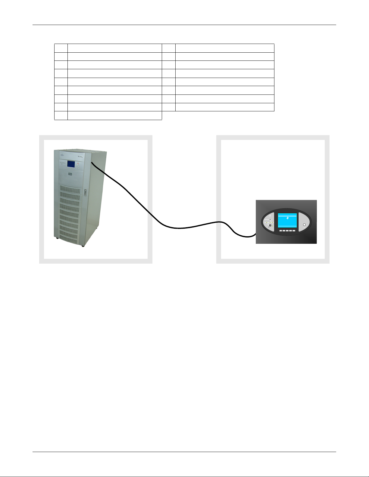
Table 1 RMP component location in Figure 1
UPS Room
Liebert NX
Communication
Cable; Maximum Length
100m (328ft.)
(field-supplied)
Maintenance or Control Room
HELPF4F3F2F1
EMERSON
™
Network Power
Liebert
®
Press any key back to m ain menu
Liebert NX
081kVA -3x3
12-16-2009
Single
12:22:14
Normal
STATUS
EMERSON
™
Network Power
SILENCE ON/OFF
Remote Monitor Panel
Liebert
NX
1 Bypass Input 10 F3 Function Key
2 Inverter—DC to AC 11 F4 Function Key
3 Rectifier—Input AC to DC 12 Help Key
4 Load—AC Output 13 Silence On/Off Audible—Alarm Mute
5 Battery—DC Backup 14 RS-232—for firmware update
6 Audible Alarm—Buzzer 15 RS-232—Reserved, not used
7 UPS Status and Alarm indicator 16 AC power input cable entry
8 F1 Function Key 17 RS-485 communication cable entry
9 F2 Function Key
Figure 2 Remote Monitoring Panel layout constraints
Introduction
3
Page 8
2.0 INSTALLATION
15.6mm
4mm
14mm
2.1 Preliminary checks
Before beginning to install the RMP, verify that the equipment has reached site in its own packaging
and in good general condition. Please notify immediately the shipper, Emerson Network Power and
your local Liebert representative of any damage.
These items should be included in the package:
• RMP box with LCD screen
• 4 mounting screws
• 4 plastic wall anchors (6mm-by-26mm)
• 2 Phoenix connectors for connection with the UPS.
• User manual
2.2 Location
The RMP is designed for indoor use and should be installed in an environment with clean air and adequate ventilation to keep the temperature within the specified operating range (see Table 17).
If the RMP is to be installed on a wall or other vertical surface, ensure that the surface can bear the
weight (see Table 16) and there is no water leakage.
Installation
2.3 Power Supply
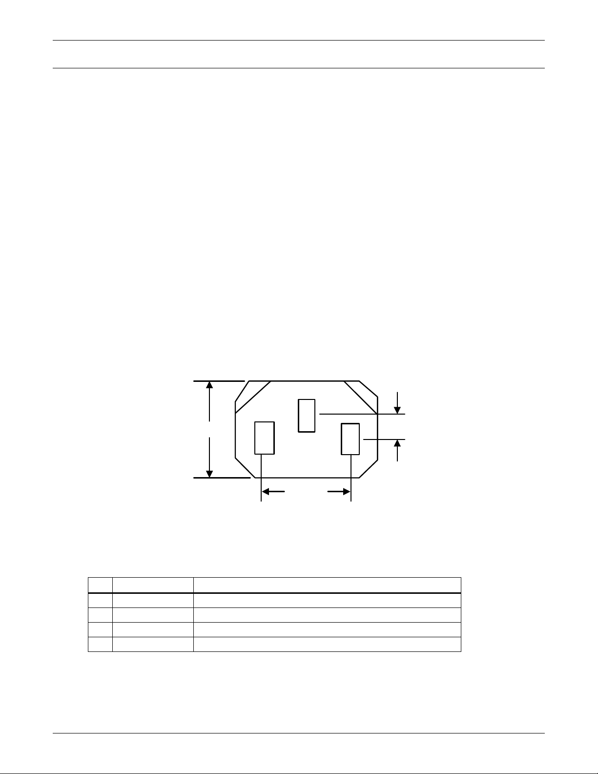
The RMP requires a 120V/230V AC input (for detailed electrical specifications, see Table 18).
Figure 3 RMP electrical input plug
2.4 Cable Specifications
Connect the RMP to the Liebert NX with a field-supplied communication cable meeting the specifications in Table 2.
Table 2 Communication cable specifications
No Item Specification
1 Connector type Both terminals are all 4-pin Phoenix terminal (supplied with RMP).
2 Cable Length <100m
3 Cable type a shielded and twisted pair of 0.5 to 1 mm
4 Connection mode See Figure 4
2
(16-20AWG) wires
4
Page 9
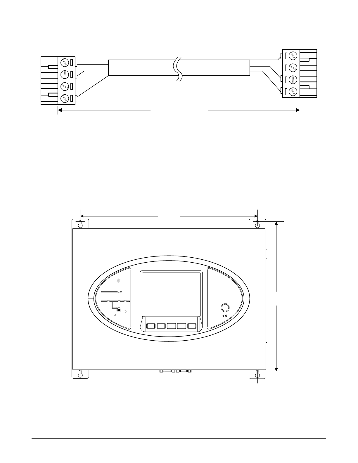
Figure 4 Communication cable connection
UPS_U2_J24
Up to 328 ft. (100 m)
RMP_X1_J1
Shield
Shield
485-
485+
485-
485+
1
2
3
4
1
2
3
4
STATUS
Remote Monitor Panel
SILEN CE ON/O FF
Liebert NX
Emerson
Network Power
TM
14-3/16"
(365mm)
12"
(306mm)
F1 F2
F4F3 HELP
2.5 Mounting the RMP on Drywall
To hang the RMP on drywall or similar surface:
1. Drill four holes (6mm-by-26mm) in the wall, spacing them as shown in Figure 5.
2. Insert the four factory-supplied, plastic anchors into the holes.
3. Insert one screw into each anchor and tighten firmly.
4. Remove the four hooks from the RMP, reverse them, then reattach them to the RMP.
5. Hang the RMP on the wall by slipping the hooks over the heads of the screws and lowering the
RMP slowly until the screws are seated in the slotted portion of the hooks.
Installation
Figure 5 Mounting hole dimensions
5
Page 10

2.6 Electrical connections
Extract four
screws to
remove the
cable access
cover
Attach AC Input
cable to labeled
connector
Attach
communication
cable to
labeled
RS-485
connector
Reinstall cable access cover,
inserting AC Input and
communication cables into
respective, labeled slots
Figure 6 Power and communication cable routing
Installation
Connect the power and communication cables to the RMP as shown in Figure 6.
6
Page 11

Connect the RS-485 communication cable to the Liebert NX as shown in Figure 7.
Communication connections
on Remote Monitoring Panel board
Figure 7 RS-485 cable connection to Liebert NX
Installation
Connect the other end of the RS-485 signal cable to the X4 slot on the monitor board. The monitor
board is inside the UPS front door.
7
Page 12

3.0 OPERATION
F2 F4 F5F1 F3
Liebert NX
2006-01-22 12:30:36
30kVA-3X3
Unit #1 Normal
?
Bypass
Main
Vphase V
Iphase A
Freq. Hz
Vline V
P. F.
A(AB)
120
20.5
50.1
208
0.99
B( BC)
120
20.5
50.1
208
0.99
C(CA)
120
20.5
50.1
208
0.99
Outp ut
Loading data from UPS
F2 F4 HELPF1 F3
Input breaker closed 01-12 12:28:16
Manual turn on 01-12 12:30:06
UPS in normal mode 01-22 12:30:16
3.1 Startup and Reset
The RMP will start as soon as the power supply is connected. The LCD will illuminate without any
data displayed; the LEDs will light up yellow.
After 20 seconds, all LEDs will turn off and the LCD will show the opening screen, shown in
Figure 8, for 10 seconds.
Figure 8 Opening screen
Operation
If all conditions above are met, the RMP will start to get all messages from the UPS. The screen in
Figure 9 will be displayed while the data is loading. The loading time is about 30 seconds.
Figure 9 Data loading progress screen
If the firmware in the UPS and the RMP are compatible, the RMP will display the screen shown in
Figure 10. The NX screen will display the same screen.
8
Page 13

Figure 10 UPS and RMP firmware are compatible screen
Liebert NX
2006-01-22 12:30:36
30kVA-3X3
Unit #1 Normal
?
System
Output
Sou t (kVA )
Pou t (kW)
Qout (kVAR)
A(AB)
10
10
0
B( BC)
10
10
0
C(CA)
10
10
0
Load
Load level (%)
Crest Factor
50
50 50
1.41.41.4
F2 F4 HELPF1 F3
Input breaker closed 01-12 12:28:16
Manual turn on 01-12 12:30:06
UPS in normal mode 01-22 12:30:16
Liebert NX
2006-01-22 12:30:36
30kVA-3X3
Unit #1 Normal
?
Bypass
Main
Vphase V
Iphase A
Freq. Hz
Vline V
P. F.
A(AB)
120
20.5
50.1
208
0.99
B( BC)
120
20.5
50.1
208
0.99
C(CA)
120
20.5
50.1
208
0.99
Outp ut
Remote Monitor Panel
silence
F2 F4 HELPF1 F3
Input breaker closed 01-12 12:28:16
Manual turn on 01-12 12:30:06
UPS in normal mode 01-22 12:30:16
Liebert NX
2006-01-22 12:30:36
30kVA-3X3
Unit #1 Normal
?
Bypass
Main
Vphase V
Iphase A
Freq. Hz
Vline V
P. F.
A(AB)
120
20.5
50.1
208
0.99
B( BC)
120
20.5
50.1
208
0.99
C(CA)
120
20.5
50.1
208
0.99
Outp ut
Remote Monitor Panel
silence off
F2 F4 HELPF1 F3
Input breaker closed 01-12 12:28:16
Manual turn on 01-12 12:30:06
UPS in normal mode 01-22 12:30:16
RMP Silence On RMP Silence Off
When the Silence On/Off button is pushed, the relevant screen in Figure 11 will be displayed for
5 seconds.
Operation
NOTE
The Silence On/Off button will control only the audible alarm in the Remote Monitoring
Panel. It will not silence the audible alarm in the UPS.
Figure 11 Silence On/Off screens
If the RMP is abnormal or the connection with the UPS is incorrect, the RMP will show the screen in
Figure 12 to report communication with UPS failed.
9
Page 14

Figure 12 Communication with UPS failed
Liebert NX
2006-01-22 12:30:36
30kVA-3X3
Unit #1 Normal
?
Bypass
Main
Vphase V
Iphase A
Freq. Hz
Vline V
P. F.
A(AB)
120
20.5
50.1
208
0.99
B( BC)
120
20.5
50.1
208
0.99
C(CA)
120
20.5
50.1
208
0.99
Outp ut
Communication with UPS
Failed
CommErrID=0x01
F2 F4 HELPF1 F3
Input breaker closed 01-12 12:28:16
Manual turn on 01-12 12:30:06
UPS in normal mode 01-22 12:30:16
Liebert NX
2006-01-22 12:30:36
30kVA-3X3
Unit #1 Normal
?
Bypass
Main
Vphase V
Iphase A
Freq. Hz
Vline V
P. F.
A(AB)
120
20.5
50.1
208
0.99
B( BC)
120
20.5
50.1
208
0.99
C(CA)
120
20.5
50.1
208
0.99
Outp ut
Firmware is n ot
Compatible with UPS
RMP:Vxxx UPS:Vxxx
F2 F4 HELPF1 F3
Input breaker closed 01-12 12:28:16
Manual turn on 01-12 12:30:06
UPS in normal mode 01-22 12:30:16
If the RMP is functioning properly and the connection with UPS is correct, but the UPS does not support the communication function with RMP, then the RMP will display a the screen shown in
Figure 13 to report “Firmware is not Compatible with UPS.”
Operation
Figure 13 Firmware not compatible with UPS screen
If the RMP determines that the UPS firmware is not compatible, after loading all messages available
from the UPS, the RMP will display the screen shown in Figure 13.
10
Page 15

3.2 LED Mimic Power Flow
The LEDs mounted on the mimic flow chart represent the various power paths and current UPS operational status.
Table 3 Rectifier indicator
Green Rectifier in Normal Operation
Flashing
Green
Red Rectifier Failed
Off Rectifier Not operating, Input AC Not Available or out of normal range
Table 4 Battery indicator
Green Battery Normal, but discharging and powering the load
Flashing
Green
Red
Off Battery and Converter Normal, Battery charging
Table 5 Bypass indicator
Green Load on Bypass power
Red Bypass not available, out of normal range or Static bypass switch fault
Off Bypass Normal, load not on bypass
Input AC Normal, but rectifier not operating
Battery End of Discharge pre-warning
Battery abnormal (Failed, Absent or Polarity Reversed) or Battery
Converter abnormal
(Failed, overcurrent, overtemperature)
Operation
Table 6 Inverter indicator
Green Inverter Normal and powering the load
Flashing
Green
Red Inverter failed
Off Inverter not operating
Inverter ON, starting up, synchronizing, or standing by (ECO mode)
Table 7 Load indicator
Green UPS output ON and Normal
Red UPS output ON and Overloaded
Off UPS output OFF.
Table 8 Status (Alarm) indicator
Green Normal Operation
Yellow UPS Warning e.g. AC Input Failure
Red UPS fault (ex. Fuse or Hardware failure)
3.3 Audible Alarms—Buzzer
UPS activity is accompanied by the following sounds
Table 9 Audible alarm key
Single beep Direct Access key acknowledgement
One beep per second UPS Warning, (ex. AC Input Failure)
Continuous beep Fault, (ex. Fuse or Hardware Failure)
11
Page 16

3.4 Direct Access Push Buttons—Keys
?
ESC
Liebert NX
20kVA 3X3
?
Out put
2006-10-22
Unit #1
17:32:20
Normal
F2 F3 F4 HELPF1
Bypass
Main
L-N
Vphase V 220
Iphase A 20.5
Freq. Hz 50.1
Vline V 380
P.F. 0.99
Input breaker closed 01-12 12:28:16
Manual turn on 01-12 12:30:06
UPS in normal mode 01-22 12:30:16
4 - Current Record
Window
3 - UPS Data
Window
2 - UPS Menu
Window
1 - UPS System
Window
5 - Keypad W indow
The NX Remote Monitoring Panel has one direct access push button: Silence ON/OFF. The Silence
ON/OFF button is a toggle type buzzer mute; any new fault re-enables the buzzer.
3.5 LCD Monitor and Menu Keys
The menu-driven, 320 x 240 dot graphic LCD monitor displays real time data and, at the same time,
stores 512 historical records that can be retrieved for reference and diagnosis.
The user can perform commands or browse through the input, output, load and battery parameters.
For quick reference, the UPS status and any warnings are always highlighted without the need of
navigating through the menu. The versions of converter firmware, inverter firmware and internal
monitor firmware can also be displayed on the LCD.
Menu keys F1 to F4 are used to navigate within the graphic LCD monitor windows.
Table 10 Menu key Icons and their meaning
Key F1 F2 F3 F4 Help
Window Type 1
Operation
Next Data Window
Window Type 2
Figure 14 Graphic LCD monitor windows and keypad
The function of keys F1 to F4 is shown by a self-explanatory icon as appropriate for the particular
window. As shown in Figure 14 above, pressing F1 moves the cursor (resting in “OUTPUT”) from the
UPS Menu Window (2) to current record window (4) where it would first rest in “Input breaker closed’.
In a similar manner, pressing F2 would move the cursor from the Output data window to the Bypass
data window.
Escape
LEFT RIGHT
UP DOWN
ENTER
HELP
12
Page 17

The summary menu tree is shown in Figure 15. Refer to Table 12 for a detailed description of each
Battery
Battery voltage (V)
Battery current (A)
Battery temperature (°C)
Remain Time Min.
Battery capacity (%)
Battery boost charging
Battery float charging
Battery disconnected
Command
Battery maintenance test
Battery capacity test
System test
Stop testing
Freshening Charge
Stop Freshening Charge
Modem Auto-answer enable
Version
UPS version
UPS model
Settings
Display contrast
Date format set
Date & time
Comm1 baud rate
Comm2 baud rate
Comm3 baud rate
Communication address
Communication mode
Callback times
Phone No.1
Phone No.2
Phone No.3
Command password
System
Sout (kVA)
Pout (kW)
Qout (kVAR)
Single unit, no
parallel data
Records
(history log)
Language
(Choices for
display)
Mains (input)
L-N voltage (V)
L-N current (A)
Frequency (Hz)
L-L voltage (V)
Power factor
Load
Sout (kVA)
Pout (kW)
Qout (kVAR)
Loadlevel %
Crest factor
Bypass
L-N voltage (V)
Frequency (Hz)
L-L voltage (V)
Output
L-N voltage (V)
L-N current (A)
Frequency (Hz)
L-L voltage (V)
Power factor
TX Input *
L-N voltage (V)
L-L voltage (V)
* When configured, input transformer voltages are
displayed on the front LCD. When not activated, the
values are hidden.
** When configured, output transformer voltages are
displayed on the front LCD. When not activated, the
values are hidden.
TX Output **
L-N voltage (V)
L-L voltage (V)
Visible from the RMP,
but the control is
available at UPS only.
Visible from the RMP,
but the control is available at UPS only.
menu item.
Figure 15 Menu tree
Operation
13
Page 18

3.6 Detailed Description of Menu Items
The description that follows refers to the graphic LCD monitor window shown on Figure 14.
UPS System Window: This fixed-pane window displays current time and date and identifies the UPS,
its configuration and its status.
Table 11 UPS system window
Description Explanation
Liebert NX UPS family name
2005-10-22 YYYY-MM-DD (see Settings menu for other date formats)
12:30:36 Current Time (24 hr HH:MM:SS format)
30kVA-3x3 30kVA = UPS rated output, 3 x 3 = 3-phase input and output
(Configuration)
Single, ECO, Master, Slave or Unit # 1
(Status)
Normal, Warning or Fault
Menu and Data Window
Single = single double-conversion unit
ECO = single stand-by unit with double-conversion fall-back
Master = master in a 1+1 Hot Stand By system
Slave = slave in a 1+1 Hot Stand By system
Unit # 1 = of max 6 double-conversion units in a parallel system
Normal = UPS operating Normal
Warning = System attention required, e.g. AC Input Failure
Fault = UPS Fuse or Hardware Failure
Operation
Use the horizontal arrow keys to navigate between any of the selectable menu and data windows.
Table 12 Descriptions of RMP menus and data window items
Menu
Type Item Type Explanation
L-N voltage (V) Phase voltage
Mains
(input)
TX Input
Bypass
Output
TX Output
Load
System
L-N current (A) Phase current
Frequency (Hz) Input frequency
L-L voltage (v Line-line voltage
Power factor Power factor
L-N voltage (V) Phase voltage
L-L voltage (V) Line-line voltage
L-N voltage (V) Phase voltage
Frequency (Hz) Bypass frequency
L-L voltage (A) Line-line voltage
L-N voltage (V) Phase voltage
L-N current (A) Phase current
Frequency (Hz) Output frequency
L-L voltage (V) Line-line voltage
Power factor Power factor
L-N voltage (V) Phase voltage
L-L voltage (V) Line-line voltage
Sout (kVA) Sout: Apparent power
Pout (kW) Pout: Active power
Qout (kVAR) Qout: Reactive power
Load level % The percent of the UPS rating load
Crest factor Output current Crest Factor
Sout (kVA) Sout: Apparent power
Pout (kW) Pout: Active power
Qout (kVAR) Qout: Reactive power
Single unit, no parallel data
When configured as a single unit, UPS has only native load, no system
load.
14
Page 19

Table 12 Descriptions of RMP menus and data window items (continued)
Menu
Type Item Type Explanation
Battery voltage (V) Battery bus voltage
Battery current (A) Battery bus current
Battery temperature (°C) Battery temperature °C
Battery
Records (history log) Displays all records in the history log
Language (choices for text displayed) User may select any of 12 languages for LCD text.
Settings
Command
(start/stop
battery &
system
tests)
Version
* Visible from the RMP, but the control is available at UPS only.
Remain Time Min. Battery run time remaining
Battery boost charging Battery is boost charging
Battery float charging Battery is float charging
Battery disconnected Battery is not connected
Display contrast Adjust the LCD display contrast
Date format set * Choose the format for date display: M/D/Y, D/M/Y, M/D/Y, Y/M/D
Date & time * Set the date and time
Comm1 baud rate * Communication baud rate setting for IntelliSlot 1
Comm2 baud rate * Communication baud rate setting for IntelliSlot 2
Comm3 baud rate * Communication baud rate setting for IntelliSlot 3
Communication address * This setting is applicable to RS485 communication mode
Communication mode * Communication Mode Setting
Callback times *
Phone No.1 *
Phone No.2 *
Phone No.3 *
Command password * User can modify the command password.
Battery maintenance test *
Battery capacity test *
System test *
Stop testing *
Freshening Charge *
Stop Freshening Charge * Manually stop a Freshening Charge
Modem Auto-answer
enable *
UPS version
UPS model Provides UPS model information—for example, 400V-50Hz.
When IntelliSlot 1 Communication mode is Modem, this parameter sets
the number of times a number is redialed to send an alarm notification.
When IntelliSlot 1 Communication mode is Modem, this is the first phone
number to be dialed (to send an alarm notification).
When IntelliSlot 1 Communication mode is Modem, this is the second
phone number to be dialed (to send an alarm notification).
When IntelliSlot 1 Communication mode is Modem, this is the third phone
number to be dialed (to send an alarm notification).
This test performs a partial discharge of the battery to obtain a rough
estimate of the battery capacity. Load must be between 20% and 100%.
This test performs a full discharge of the battery to obtain a precise
measure of the battery capacity. Load must be between 20% and 100%.
This is a self-test of the UPS. When the user activates this function, a
popup window appears about 5 seconds later to show the results.
Manually stops a battery maintenance test, battery capacity test or system
test.
This command will allow a temporary Equalize charge for the batteries.
This charge is configurable for 1 to 36 hours
Manually enable the auto-answer function of modem.
Provides UPS firmware version numbers for the inverter, rectifier and
software display board.
Operation
Current Record Window
Keeps a log the events that resulted in the current mode of operation. Ignores transient conditions
that have been resolved. Use “page” (F1) and up / down arrow to read the events.
For a complete history log, refer to the Records tab of the Menu and Data Window.
Refer to Table 13 for a complete list of supported status messages.
15
Page 20

3.7 Status and Event Messages
Refer to Table 13 for descriptions of events and alarms.
Table 13 RMP messages
Message Description / Suggested Action (if any)
Inverter Comm. Fail Internal RS485 communication failure between monitor and inverter
Rectifier Comm. Fail Internal RS485 communication failure between monitor and rectifier
The CAN communication between different UPSs within a parallel system fails.
Parallel Comm. Fail
Battery Overtemp. The Battery temperature is over limit. Check the battery temperature and ventilation
Ambient Overtemp. The Ambient temperature is over limit. Check the ventilation of UPS room.
Battery Fault Battery detected faulty (Reserved)
Replace Battery Battery test failed, Battery should be replaced.
Battery Low Pre-warning
Battery End of Discharge Inverter turned off due to low battery voltage. Check the utility failure and try to recover it.
Mains Volt. Abnormal
Mains Undervoltage
Mains Freq. Abnormal
Rectifier Fault Rectifier detected faulty. Rectifier shuts down. Battery discharges.
Rectifier Overtemp.
Batt. Contactor Fail Battery contactor or circuit breaker not responding to control signals.
Batt. Charger Fault The voltage of the battery charger is too high.
Control Power 1 Fail UPS operates but Redundant Control Power is not available.
Mains Phase Reversed AC Input phase sequence is reversed.
Rectifier Overcurrent Rectifier is overloaded.
Soft Start Fail Rectifier could not start due to low DC bus voltage
Bypass Unable to Trace
Bypass Abnormal
1. Check if there are some UPSs not powered on in the parallel system. If so, power on these
UPSs and check if the alarm disappears.
2. Press Fault Clear push button.
Before the end of discharge, battery undervoltage pre-warning should occur. After this prewarning, battery should have the capacity for 3 minutes discharging with full load. The time is
user-configured from 3 to 60 minutes.
Shut down the load in time.
Mains Voltage exceeds the upper or lower limit and results in rectifier shutdown.
Check the input line-to-neutral voltage amplitude of rectifier.
Mains Voltage is undervoltage with derated load.
Check the input line-to-line voltage amplitude of rectifier
Mains frequency is out of limit range and results in rectifier shutdown.
Check the rectifier’s input voltage frequency
The temperature of heat sink is too high to keep the rectifier running.
The UPS can recover automatically. Check the environment and ventilation.
This alarm is triggered by an inverter software routine when the amplitude or frequency of
bypass voltage is beyond the normal range.
The amplitude threshold is fixed for positive and negative 10% rating.
This alarm automatically resets once the bypass voltage goes normal.
1. First verify that the bypass voltage and frequency displayed on the panel is within the
selected range. Note here the rated voltage and frequency are specified by “Output voltage
level” and “Output frequency level” respectively.
2. If the displayed voltage is believed to be abnormal, then verify the bypass voltage and
frequency presented to the UPS. Check the external supply if it is found to be faulty.
This alarm is triggered by an inverter software routine when the amplitude or frequency of
bypass voltage exceeds the limit.
This alarm automatically resets once the bypass voltage goes normal.
First check if there are some relevant alarms such as “Bypass disconnect open”, “Bypass phase
reverse” and “Mains neutral lost”. If they appear, solve them first.
1. Then verify that the bypass voltage and frequency displayed on the panel is within the bypass
limit. Note here the rated voltage and frequency are specified by “Output voltage level” and
“Output frequency level” respectively.
2. If the displayed voltage is believed to be abnormal, then verify the bypass voltage and
frequency presented to the UPS. Check the external bypass supply if it is found to be faulty. If
the utility is likely to trigger this alarm frequently, the bypass limit can be changed a little larger
through the configuration software according to the customer’s agreement.
Operation
16
Page 21

Operation
Table 13 RMP messages (continued)
Message Description / Suggested Action (if any)
This alarm is triggered by an inverter software routine when the inverter and bypass waveforms
are misaligned by more than 6 degrees in phase. This alarm resets automatically once the
condition is no longer true.
Inverter Asynchronous
Inverter Fault Inverter output voltage beyond limits. Load transfers to bypass.
Inverter Overtemp.
Fan Fault At least one of the cooling fans has failed
Inverter STS Fail
Bypass STS Fail
Operation Invalid This record is registered following an incorrect operation:
Output Fuse Fail At least one of the inverter output fuses is blown. Inverter shuts down. Load transfers to bypass.
Control Power 2 Fail UPS operates but Redundant Control Power is not available.
Unit Over load
System Over load
Unit Over load Timeout
Byp. Abnormal Shutdown Both bypass and inverter voltages unavailable. Load interruption
Inverter Over Current Inverter Pulse Width Modulation module overloaded.
1. First check if the alarm “Bypass unable to trace” or “Bypass abnormal” occurs. If so, solve it
first.
2. Verify the waveform of the bypass voltage. If it is too distorted, ask the customer to verify and
seek any possible measurements.
The temperature of the inverter heat sink is too high to keep inverter running.
This alarm is triggered by the signal from a temperature monitoring thermostat on the inverter
bridge heat sink.
The UPS will recover automatically after a 5 minute delay from the disappearance of the
overtemperature signal.
If the overtemperature condition is true, then check for and verify:
1. high ambient air temperature.
2. blocked cooling airway.
3. any fan failure.
4. prolonged inverter overload
At least one of the static switches of inverter side is open or short circuit. This fault is locked until
power off.
At least one of the static switches of bypass side is open or short circuit. This fault is locked until
power off
The UPS is confirmed to be overload when the load arises above 105% nominal rating.
The alarm automatically resets once the overload condition is removed.
1. Confirm that the alarm is true by checking the load percent indicated on the LCD panel to
determine which phase is being overloaded.
2. If the alarm is true, measure the actual output current to verify that the indications are valid.
Disconnect unnecessary load and ensure the safety. In a parallel system, a severe load sharing
error can also leads to the alarm.
The UPS parallel system is confirmed to overload when the total load arises above 105%
nominal rating for the set basic number of UPSs. The alarm automatically resets once the
overload condition is removed.
1. Confirm that the alarm is true by checking the system load percent indicated on the LCD
panel to determine which phase is being overloaded.
2. If the alarm is true, measure the actual output current to verify that the indications are valid.
Disconnect unnecessary load and ensure the safety. In a parallel system, a severe load sharing
error can also leads to the alarm.
The UPS is confirmed to overload and the overload times out.
Note 1: the highest loaded phase will indicate overload timing-out first.
Note 2: When the timer is active then alarm “unit overload” should also be active as the load is
above nominal.
Note 3: When the timer has expired, the inverter Static Switch is opened and the load
transferred to bypass. The inverter shutdown and will restart after 10 seconds.
Note 4: If the load decreases lower than 95% after 5 minutes, the system will transfer back to
inverter mode.
Confirm that the alarm is genuine by checking the load percent indicated on the LCD. If an
overload is indicated then check the load, and investigate any additional load connected prior to
the alarm (if applicable).
17
Page 22

Operation
Table 13 RMP messages (continued)
Message Description / Suggested Action (if any)
The phase sequence direction of bypass voltage is reversed.
Bypass Phase Reversed
Load Impact Transfer
Transfer Time-out
Load Sharing Fault UPS modules within a parallel system are not sharing the load current equally.
DC Bus Abnormal DC input voltage to inverter beyond limits. Inverter shuts down. Load transfers to bypass.
System Transfer
Parallel Board Fault
DC Bus Over Voltage
Parallel Connect Fault
Bypass Over Current Bypass current is over limit above 135% rating. The UPS just alarms and does nothing.
LBS Active
Setting Save Error History records not saved. (Reserved)
Mains Neutral Lost AC Input mains reference neutral not detected.
Protocol version clash Firmware incompatibility between Monitor Board and Digital Signal Processor Board.
Battery ground fault Battery leakage to ground detected (option)
Inv. Turned On Manually Manual Turn On via front panel
Inv. Turned Off Manually Manual Turn Off via front panel
EPO Emergency Power Off direct access key pressed or external command received
Transfer Confirm
Transfer Cancel Prompt to press “ESC” key to avoid that an interrupted load transfer to bypass will happen.
Unit Off Confirm
System Off Confirm
Fault Reset Fault clear direct access key pressed
Alarm Silence Silence On/Off direct access key pressed
Turn On Fail
Alarm Reset Fault clear or Silence On/Off direct access key pressed
Bypass Mode Load supplied from AC input bypass supply.
Normal Mode Load supplied from Inverter output through double conversion of the AC mains input supply.
Battery Mode Load supplied from Inverter output through double conversion of the Battery supply.
Source share mode
Normally, the phase of phase B lags 120 degrees behind phase A, and the phase of phase C
lags 120 degrees behind phase B.
Verify that the phase rotation of the bypass supply presented to the UPS is correct, and rectify it
if it is found to be in error
A transfer to bypass occurred due to a large step load. The UPS should recover automatically.
Turn on connected equipment in sequential order to reduce the step loading of the inverter.
The load is on bypass power due to excessive number of transfers that occurred within the last
hour.
The UPS will recover automatically and will transfer the load back to inverter power within an
hour.
The whole paralleled UPS system transferred to bypass at the same time. This message will
appear on the UPS which passive transfer to bypass
Malfunction of the paralleling control circuits of this UPS module. Can cause “System Transfer”
to bypass.
Rectifier, inverter and battery converter were shutdown because DC bus voltage is too high.
Check whether there is a fault in rectifier side. If no, then check whether overload occurs.
Restart the inverter after resetting the fault
The parallel cables are not connected correctly in a parallel system.
Reset the fault by pressing the “fault clear” button, then restart the inverter by pressing the
“inverter on” button.
Load Bus Synchronization is active. The UPS is acting as an LBS master or slave in a dual bus
configuration.
Prompt to press “enter” key to acknowledge that an interrupted load transfer to bypass will
happen.
Prompt to press “enter” key to acknowledge that the UPS will be disconnected from other
paralleled UPS modules.
Prompt to press “enter” key to acknowledge that the all paralleled UPS will be disconnected
from the load.
Inverter failed to turn on when Inverter On direct access key was pressed. This may be as a
result of Invalid Operation (Maintenance bypass on) or DC bus or rectifier not ready.
Load supplied from Inverter output through shared double conversion of the AC mains input
supply and of the Battery supply.
18
Page 23

Operation
Table 13 RMP messages (continued)
Message Description / Suggested Action (if any)
UPS Shutdown UPS Shutdown, output power-down
Check UPS Output Inverter off during normal startup (diagnostics information only)
Generator Connected Generator active signal received. Source share mode may be activated pending UPS settings.
BCB open Battery Circuit Breaker status (open)
BCB closed Battery Circuit Breaker status (closed)
Battery Float Charging Battery status (Float charge mode)
Battery Boost Charging Battery status (Boost charge mode)
Battery Discharging Battery status (discharge mode)
Battery Period Testing Automatic periodic battery maintenance discharge test (20% capacity discharge)
Batt. Capacity Testing User initiated battery capacity discharge test (100% capacity discharge)
Batt. Maint. Testing User initiated maintenance discharge test (20% capacity discharge)
UPS System Testing User initiated UPS self test
Inverter in Setting Inverter starting up and synchronizing
Rectifier in Setting Rectifier starting up and synchronizing
MBP-T cabinet Fan Fault Maintenance bypass cabinet fans fault.
Ext Input TX Overtemp External Input Isolation Transformer Over Temperature
Ext Output TX Overtemp External Output Isolation Transformer Over Temperature
Battery Room Alarm Environment in Battery Room Needs Attention
Rotary Sw. Test Pos. Rotary switch is in test position.
Rotary Sw. Normal Pos. Rotary switch is in normal position.
Rotary Sw. Bypass Pos. Rotary switch is in bypass position.
Rotary Sw. Maint. Pos. Rotary switch is in maintenance position.
Battery Contactor Open Battery Contactor Open
Battery Contactor Close Battery Contactor Closed
Battery Reverse Connect the battery again and check the wiring of batteries
No Battery Check the battery and the wiring of batteries
Auto start After UPS was shutdown at EOD, inverter auto starts when utility restore
Rec. Flash Update Rectifier firmware is being update
Inv. Flash Update Inverter firmware is being update
Monitor Flash Update Monitor firmware is being update
Input contactor fault Input contactor is in fault
Contactor P.S. 1 fault Contactor Power Supply board 1 Fault
Contactor P.S. 2 fault Contactor Power Supply board 2 Fault
LBS abnormal LBS is abnormal
DSP firmware error The inverter firmware does not match with the rectifier firmware.
19
Page 24

3.8 Prompt (Popup) Windows
The prompt window is displayed during the operation of the system to alert the user to certain conditions and / or to require user confirmation of a command.
NOTE
The items in Table 14 are visible form the RMP, but the controls for them are available only at
the UPS.
Table 14 Prompt windows, meanings controlled at UPS only
Prompt Meaning
Transfer with interrupt, please confirm or cancel
The load is too high to be transferred with interrupt
This Operation Leads to Output Shutdown, Confirm or
Cancel
This operation leads to inverter overload, confirm or
cancel
Turn on more UPS to carry current load
Battery will be depleted, confirm Battery Capacity test discharges the battery 100%
System self test finished - everything is ok. No action required
System self test finished - Please check the current
warnings.
Enter control password Required for Battery or UPS test (default = 12345)
Battery Self Test aborted, condition not met
Battery Refresh Charge aborted, condition not met
Operation
Inverter and Bypass supplies are not synchronized and
any load transfer between the supplies will cause a brief
load interruption.
The total load must be less than the capacity of one unit
to allow a parallel system to perform an interrupted
transfer from bypass to inverter.
No alternative supply is available and any Inverter Off
operation will cause the load to be de-energized.
The turn-off this inverter will lead to the overload of
remaining inverter(s) in a parallel system.
The number of paralleled inverters already turned on is
insufficient to carry the existing load.
Check “Current Records” window
Battery self-test condition is not enough. User should
check whether battery state is boost charging and
whether load level is greater than 20 percent.
Boost charging condition is not enough, such as (No
battery, charger has failed, etc.).
Table 15 Prompt windows, meanings controlled at RMP
Prompt Meaning
Communication with UPS failed The communication between RMP and UPS failed.
Loading data from UPS
Remote Monitoring Panel silence
Remote Monitoring Panel silence off
Remote Monitoring Panel firmware updating
Firmware is not compatible with UPS
The RMP are loading data from UPS
The RMP unit has been muted.
The RMP silence is off
The RMP are updating firmware from ParameSet tool.
The RMP firmware is not compatible with UPS
3.9 Dynamic Energy Flow Chart and UPS Help Screen
This screen displays a mimic diagram of the UPS that includes energy flow and status of isolation and
transfer switches. Press the “Help” key to activate this screen. Press “Help” again to toggle between
this screen and the main screen.
20
Page 25

Figure 16 Help screen
F2 F4 HELPF1 F3
Help information
Select the previous menu item
Select the current record window
Q3
Q2
Q1
Q5
Press help key back to main menu
F2 F3 F4 HELPF1
Liebert NX 2005-05-22 12:30:36
20 kVA-3x3 UNIT #1 NORMAL
Press any key, back to main menu
3.10 Default screen saver
Operation
This default screen is displayed following 2 minutes of operation with no new alarm or activity. After
another 2 minutes of inactivity, the backlight turns off. Press any key (F1-F4 or Help) to reactivate
the screen.
Figure 17 Default screen
21
Page 26

4.0 TECHNICAL SPECIFICATIONS
Table 16 Mechanical specifications
Mechanical
Characteristics Units Value
Height mm 100
Width mm 400
Depth mm 290
Weight kg 5.28
Ventilation - Air cooling
Cable entry - Left side
Color - Black
Protection
Grade
Table 17 Environmental specifications
Environmental Characteristics Units Value
Operating Temperature °C 0~40
Relative humidity — 90% or less at 20°C
Acoustical noise dBA <32
Altitude of operation m <2000
Storage-transport temperature °C -25 ~70
-IP 20
Technical Specifications
Table 18 Electrical specifications
Electrical Characteristics Units Value
Rated input voltage VAC 100,120, 220, 230, 240
Input voltage range VAC 90-254
Input Frequency Hz 50/60
Input frequency tolerance Hz 47-67
Input Current A 0.7A Max
Table 19 Cable specifications
Item Specification
Input power cable * 3-pin plug containing L+N+E
RS-485 signal cable *
* These cables must be field-supplied.
a shielded and twisted pair of 0.5 to 1 mm
(16-20 AWG)
2
wires
22
Page 27

4.1 Agency and Certifications
Safety Standard: IEC/EN/AS 62040-1-1 incorporating applicable portions of IEC/EN/UL/AS 60950-1
Certification: CE and UL 60950-1:2003, First Edition CSA C22.2 No. 60950-1-03 1st Ed.
Electromagnetic Compatibility Standard: IEC/EN/AS 62040-2 incorporating applicable portions
of emission and immunity standards as detailed in Tables 20 and 21 below.
Table 20 Electromagnetic interference (EMI)—emission limits
Standard IEC/EN/AS Class
Harmonic Current 61000-3-2 -
Voltage Fluctuations & Flicker 61000-3-3 -
Conducted RFI CISPR 22 A
Radiated RFI CISPR 22 A
Table 21 Electromagnetic susceptibility (EMS)—immunity levels
Standard
Electrostatic Discharge
Radiated Electric Fields
Fast Electrical Transients
Surges
Continuous Conducted Interfer.
Magnetic Field at Power Freq
Voltage Dips and Short
Interruptions
Low Frequency Signals
Technical Specifications
IEC/EN/AS Requirement Level Criterion
61000-4-2
61000-4-3
61000-4-4
61000-4-5
61000-4-6
61000-4-8
61000-4-11
61000-2-2 10V 140Hz-250Hz-360Hz
6 kV contact, 8 kV air 3 B
10 V/m 3 A
2 kV / 5 kHz (Power and Signal ports) 3 B
Power port
2kV (common mode)
1kV (differential mode)
Signal port
1kV
10V 3 A
30A/m - B
70%Ut:
1ms, 3ms, 10ms — A
30ms, 100ms, 300ms, 1000ms — B
40%Ut:
1ms, 3ms — A
10ms, 30ms, 100ms, 300ms, 1000ms — B
0%Ut
1ms A
3ms, 10ms, 30ms, 100ms, 300ms, 1000ms — B
3B
—A
23
Page 28

Ensuring The High Availability
Of Mission-Critical Data And Applications.
Emerson Network Power, the global leader in enabling business-critical
continuity, ensures network resiliency and adaptability through
a family of technologies—including Liebert power and cooling
technologies—that protect and support business-critical systems.
Liebert solutions employ an adaptive architecture that responds
to changes in criticality, density and capacity. Enterprises benefit
from greater IT system availability, operational flexibility and
reduced capital equipment and operating costs.
While every precaution has been taken to ensure the accuracy
and completeness of this literature, Liebert Corporation assumes no
responsibility and disclaims all liability for damages resulting from use of
this information or for any errors or omissions.
© 2008 Liebert Corporation
All rights reserved throughout the world. Specifications subject to change
without notice.
® Liebert is a registered trademark of Liebert Corporation.
All names referred to are trademarks
or registered trademarks of their respective owners.
SL-25415_REV01_01-09
Technical Support / Service
Web Site
www.liebert.com
Monitoring
800-222-5877
Liebert.monitoring@emerson.com
Outside the US: 614-841-6755
Single-Phase UPS
800-222-5877
upstech@emersonnetworkpower.com
Outside the US: 614-841-6755
Three-Phase UPS
800-543-2378
powertech@emersonnetworkpower.com
Environmental Systems
800-543-2778
Outside the United States
614-888-0246
Locations
United States
1050 Dearborn Drive
P.O. Box 29186
Columbus, OH 43229
Europe
Via Leonardo Da Vinci 8
Zona Industriale Tognana
35028 Piove Di Sacco (PD) Italy
+39 049 9719 111
Fax: +39 049 5841 257
Asia
7/F Dah Sing Financial Centre
108 Gloucester Road
Wanc hai
Hong Kong
852 2572 2201
Fax: 852 2519 9210
Emerson Network Power.
The global leader in enabling Business-Critical Continuity.
AC Power
Connectivity
DC Power
Business-Critical Continuity, Emerson Network Power and the Emerson Network Power logo are trademarks and service marks of Emerson Electric Co.
©2008 Emerson Electric Co.
Embedded Computing
Embedded Power Power Switching & Controls
Monitoring
Outside Plant
Precision Cooling
EmersonNetworkPower.com
Racks & Integrated Cabinets
Services
Surge Protection
 Loading...