

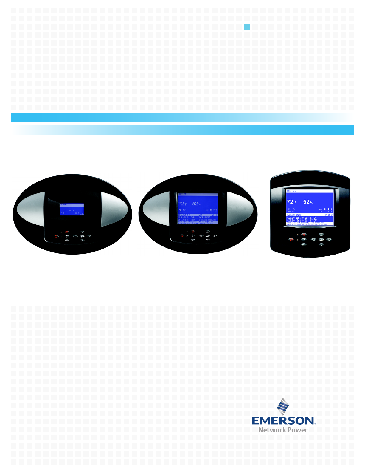
Emerson Liebert Challenger 3000, LiebertChallenger ITR, Liebert DS, Liebert iCOM User Manual
Page 1
Precision Cooling
For Business-Critical Continuity™
Liebert® iCOM
®
User Manual - Intelligent Communications & Monitoring for Liebert Challenger 3000™, Liebert
Challenger ITR™ and Liebert DS
™
Page 2

Page 3

TABLE OF CONTENTS
1.0 INTRODUCTION . . . . . . . . . . . . . . . . . . . . . . . . . . . . . . . . . . . . . . . . . . . . . . . . . . . . . . . . . .1
1.1 Features . . . . . . . . . . . . . . . . . . . . . . . . . . . . . . . . . . . . . . . . . . . . . . . . . . . . . . . . . . . . . . . . . . . 1
2.0 LIEBERT ICOM DISPLAY COMPONENTS AND FUNCTIONS . . . . . . . . . . . . . . . . . . . . . . . . . . . 2
2.1 Navigating Through the Liebert iCOM Menus . . . . . . . . . . . . . . . . . . . . . . . . . . . . . . . . . . . . 5
2.1.1 Control Interface. . . . . . . . . . . . . . . . . . . . . . . . . . . . . . . . . . . . . . . . . . . . . . . . . . . . . . . . . . . . . . 5
2.1.2 Accessing Submenus . . . . . . . . . . . . . . . . . . . . . . . . . . . . . . . . . . . . . . . . . . . . . . . . . . . . . . . . . . 5
2.1.3 Entering a Password . . . . . . . . . . . . . . . . . . . . . . . . . . . . . . . . . . . . . . . . . . . . . . . . . . . . . . . . . . 6
2.1.4 Viewing Multiple Units with a Networked Large Display. . . . . . . . . . . . . . . . . . . . . . . . . . . . . 8
3.0 OPERATION . . . . . . . . . . . . . . . . . . . . . . . . . . . . . . . . . . . . . . . . . . . . . . . . . . . . . . . . . . .12
3.1 Single Unit Functions . . . . . . . . . . . . . . . . . . . . . . . . . . . . . . . . . . . . . . . . . . . . . . . . . . . . . . . 12
3.1.1 Unit/Fan Control . . . . . . . . . . . . . . . . . . . . . . . . . . . . . . . . . . . . . . . . . . . . . . . . . . . . . . . . . . . . 12
3.1.2 General Compressor Requirements. . . . . . . . . . . . . . . . . . . . . . . . . . . . . . . . . . . . . . . . . . . . . . 15
3.1.3 Compressor Timing—Short-Cycle Protection . . . . . . . . . . . . . . . . . . . . . . . . . . . . . . . . . . . . . . 16
3.1.4 Compressor Sequencing on Two-Compressor Units . . . . . . . . . . . . . . . . . . . . . . . . . . . . . . . . . 16
3.1.5 Motorized Ball Valve in Digital Scroll Units . . . . . . . . . . . . . . . . . . . . . . . . . . . . . . . . . . . . . . 16
3.1.6 MBV Operation After Compressor is Turned Off . . . . . . . . . . . . . . . . . . . . . . . . . . . . . . . . . . . 17
3.1.7 Service Offset—Changing System Pressure Settings . . . . . . . . . . . . . . . . . . . . . . . . . . . . . . . 17
3.2 Temperature Control—Single Source Cooling (No Extra Cooling Coil) . . . . . . . . . . . . . . . . 18
3.2.1 Temperature Proportional Band . . . . . . . . . . . . . . . . . . . . . . . . . . . . . . . . . . . . . . . . . . . . . . . . 18
3.2.2 Compressor Control . . . . . . . . . . . . . . . . . . . . . . . . . . . . . . . . . . . . . . . . . . . . . . . . . . . . . . . . . . 19
3.2.3 Chilled Water Control . . . . . . . . . . . . . . . . . . . . . . . . . . . . . . . . . . . . . . . . . . . . . . . . . . . . . . . . 22
3.3 Temperature Control—Second Cooling Source . . . . . . . . . . . . . . . . . . . . . . . . . . . . . . . . . . . 23
3.3.1 Differential Temperatures / Controls (Comparator Circuit) . . . . . . . . . . . . . . . . . . . . . . . . . . 23
3.4 Temperature Control—Reheat . . . . . . . . . . . . . . . . . . . . . . . . . . . . . . . . . . . . . . . . . . . . . . . . 25
3.4.1 Three-Stage Electric, Hot Gas and Hot Water Reheat. . . . . . . . . . . . . . . . . . . . . . . . . . . . . . . 25
3.4.2 SCR Reheat . . . . . . . . . . . . . . . . . . . . . . . . . . . . . . . . . . . . . . . . . . . . . . . . . . . . . . . . . . . . . . . . . 25
3.5 Humidity Control . . . . . . . . . . . . . . . . . . . . . . . . . . . . . . . . . . . . . . . . . . . . . . . . . . . . . . . . . . . 27
3.5.1 Humidification . . . . . . . . . . . . . . . . . . . . . . . . . . . . . . . . . . . . . . . . . . . . . . . . . . . . . . . . . . . . . . 28
3.5.2 Dehumidification . . . . . . . . . . . . . . . . . . . . . . . . . . . . . . . . . . . . . . . . . . . . . . . . . . . . . . . . . . . . 29
3.6 Control Types . . . . . . . . . . . . . . . . . . . . . . . . . . . . . . . . . . . . . . . . . . . . . . . . . . . . . . . . . . . . . . 30
3.6.1 Temperature and Humidity Control Types. . . . . . . . . . . . . . . . . . . . . . . . . . . . . . . . . . . . . . . . 30
3.6.2 Humidity Sensor Reading Control Types . . . . . . . . . . . . . . . . . . . . . . . . . . . . . . . . . . . . . . . . . 31
3.7 Supply Control . . . . . . . . . . . . . . . . . . . . . . . . . . . . . . . . . . . . . . . . . . . . . . . . . . . . . . . . . . . . . 33
3.7.1 Supply Air . . . . . . . . . . . . . . . . . . . . . . . . . . . . . . . . . . . . . . . . . . . . . . . . . . . . . . . . . . . . . . . . . . 33
3.8 Event Types and Properties. . . . . . . . . . . . . . . . . . . . . . . . . . . . . . . . . . . . . . . . . . . . . . . . . . . 34
3.8.1 High- and Low-Temperature and Humidity Events . . . . . . . . . . . . . . . . . . . . . . . . . . . . . . . . 36
3.8.2 User Inputs . . . . . . . . . . . . . . . . . . . . . . . . . . . . . . . . . . . . . . . . . . . . . . . . . . . . . . . . . . . . . . . . . 36
3.8.3 Liebert iCOM-DO . . . . . . . . . . . . . . . . . . . . . . . . . . . . . . . . . . . . . . . . . . . . . . . . . . . . . . . . . . . . 37
3.8.4 Possible Event Notifications . . . . . . . . . . . . . . . . . . . . . . . . . . . . . . . . . . . . . . . . . . . . . . . . . . . 38
i
Page 4

3.9 Wellness—Next Maintenance Calculation . . . . . . . . . . . . . . . . . . . . . . . . . . . . . . . . . . . . . . . 38
3.9.1 Calculation of Next Maintenance and Diagnostics. . . . . . . . . . . . . . . . . . . . . . . . . . . . . . . . . . 39
4.0 TEAMWORK . . . . . . . . . . . . . . . . . . . . . . . . . . . . . . . . . . . . . . . . . . . . . . . . . . . . . . . . . . .41
4.1 Teamwork Modes . . . . . . . . . . . . . . . . . . . . . . . . . . . . . . . . . . . . . . . . . . . . . . . . . . . . . . . . . . . 41
4.1.1 Application of Teamwork Modes . . . . . . . . . . . . . . . . . . . . . . . . . . . . . . . . . . . . . . . . . . . . . . . . 41
4.1.2 No Teamwork . . . . . . . . . . . . . . . . . . . . . . . . . . . . . . . . . . . . . . . . . . . . . . . . . . . . . . . . . . . . . . . 41
4.1.3 Teamwork Mode 1 . . . . . . . . . . . . . . . . . . . . . . . . . . . . . . . . . . . . . . . . . . . . . . . . . . . . . . . . . . . 41
4.1.4 Teamwork Mode 2 . . . . . . . . . . . . . . . . . . . . . . . . . . . . . . . . . . . . . . . . . . . . . . . . . . . . . . . . . . . 43
4.1.5 Standby—Rotation . . . . . . . . . . . . . . . . . . . . . . . . . . . . . . . . . . . . . . . . . . . . . . . . . . . . . . . . . . . 43
5.0 INSTALLING A LIEBERT ICOM UNIT-TO-UNIT NETWORK. . . . . . . . . . . . . . . . . . . . . . . . . . .44
5.1 Placement of Cooling Units . . . . . . . . . . . . . . . . . . . . . . . . . . . . . . . . . . . . . . . . . . . . . . . . . . . 44
5.1.1 Balancing Operating and Standby Units . . . . . . . . . . . . . . . . . . . . . . . . . . . . . . . . . . . . . . . . . 44
5.2 U2U Hardware: Cables and Network Switch . . . . . . . . . . . . . . . . . . . . . . . . . . . . . . . . . . . . . 45
5.3 Wiring for Unit-to-Unit Communications—U2U . . . . . . . . . . . . . . . . . . . . . . . . . . . . . . . . . . 46
5.3.1 Wiring a Liebert iCOM U2U Network . . . . . . . . . . . . . . . . . . . . . . . . . . . . . . . . . . . . . . . . . . . 46
6.0 EXTERNAL COMMUNICATIONS—BUILDING MANAGEMENT SYSTEMS, LIEBERT
SITESCAN® . . . . . . . . . . . . . . . . . . . . . . . . . . . . . . . . . . . . . . . . . . . . . . . . . . . . . . . . . . .52
7.0 USER MENU PARAMETERS . . . . . . . . . . . . . . . . . . . . . . . . . . . . . . . . . . . . . . . . . . . . . . . .53
8.0 SERVICE MENU PARAMETERS. . . . . . . . . . . . . . . . . . . . . . . . . . . . . . . . . . . . . . . . . . . . . . 60
FIGURES
Figure 1 Liebert iCOM components . . . . . . . . . . . . . . . . . . . . . . . . . . . . . . . . . . . . . . . . . . . . . . . . . . . . . . . . . 1
Figure 2 Liebert iCOM display components . . . . . . . . . . . . . . . . . . . . . . . . . . . . . . . . . . . . . . . . . . . . . . . . . . . 2
Figure 3 Status menu, large display, graphical view. . . . . . . . . . . . . . . . . . . . . . . . . . . . . . . . . . . . . . . . . . . . 4
Figure 4 Liebert iCOM default screen symbols . . . . . . . . . . . . . . . . . . . . . . . . . . . . . . . . . . . . . . . . . . . . . . . . 4
Figure 5 Menu tree—Small display, stand-alone or networked . . . . . . . . . . . . . . . . . . . . . . . . . . . . . . . . . . . 5
Figure 6 Entering a password . . . . . . . . . . . . . . . . . . . . . . . . . . . . . . . . . . . . . . . . . . . . . . . . . . . . . . . . . . . . . . 7
Figure 7 Menu tree—Large display, stand-alone. . . . . . . . . . . . . . . . . . . . . . . . . . . . . . . . . . . . . . . . . . . . . . . 7
Figure 8 Menu tree—Large display, networked. . . . . . . . . . . . . . . . . . . . . . . . . . . . . . . . . . . . . . . . . . . . . . . . 8
Figure 9 User menu icons . . . . . . . . . . . . . . . . . . . . . . . . . . . . . . . . . . . . . . . . . . . . . . . . . . . . . . . . . . . . . . . . . 9
Figure 10 Service menu icons . . . . . . . . . . . . . . . . . . . . . . . . . . . . . . . . . . . . . . . . . . . . . . . . . . . . . . . . . . . . . . 10
Figure 11 Start-stop priority switches . . . . . . . . . . . . . . . . . . . . . . . . . . . . . . . . . . . . . . . . . . . . . . . . . . . . . . . 12
Figure 12 Temperature proportional band . . . . . . . . . . . . . . . . . . . . . . . . . . . . . . . . . . . . . . . . . . . . . . . . . . . . 18
Figure 13 One single-step compressor without unloaders. . . . . . . . . . . . . . . . . . . . . . . . . . . . . . . . . . . . . . . . 19
Figure 14 Two single-step compressors without unloaders or one compressor with an unloader
(two-step) . . . . . . . . . . . . . . . . . . . . . . . . . . . . . . . . . . . . . . . . . . . . . . . . . . . . . . . . . . . . . . . . . . . . . . 19
Figure 15 Two compressors with unloaders (four-step) . . . . . . . . . . . . . . . . . . . . . . . . . . . . . . . . . . . . . . . . . . 20
Figure 16 Digital scroll capacity modulation, 10-100% variable. . . . . . . . . . . . . . . . . . . . . . . . . . . . . . . . . . . 20
Figure 17 Single and dual digital scroll compressor activation points . . . . . . . . . . . . . . . . . . . . . . . . . . . . . . 21
Figure 18 DIP switch locations on Liebert iCOM control board . . . . . . . . . . . . . . . . . . . . . . . . . . . . . . . . . . . 22
Figure 19 Chilled water valve control (example: cooling) . . . . . . . . . . . . . . . . . . . . . . . . . . . . . . . . . . . . . . . . 23
Figure 20 Second cooling source and two-step compressorized cooling . . . . . . . . . . . . . . . . . . . . . . . . . . . . . 24
ii
Page 5

Figure 21 Three-stage heating . . . . . . . . . . . . . . . . . . . . . . . . . . . . . . . . . . . . . . . . . . . . . . . . . . . . . . . . . . . . . 25
Figure 22 Two single-step compressors with SCR reheat set to Tight mode . . . . . . . . . . . . . . . . . . . . . . . . . 26
Figure 23 Two single-step compressors with SCR reheat set to Standard mode . . . . . . . . . . . . . . . . . . . . . . 27
Figure 24 Humidity proportional band. . . . . . . . . . . . . . . . . . . . . . . . . . . . . . . . . . . . . . . . . . . . . . . . . . . . . . . 27
Figure 25 Placing temperature and temperature/humidity sensors. . . . . . . . . . . . . . . . . . . . . . . . . . . . . . . . 32
Figure 26 Teamwork Mode 1 with two cooling units . . . . . . . . . . . . . . . . . . . . . . . . . . . . . . . . . . . . . . . . . . . . 42
Figure 27 Standby unit layout example—10 Precision Cooling units in room. . . . . . . . . . . . . . . . . . . . . . . . 44
Figure 28 Connecting two cooling units, each with a small display using a crossover Ethernet cable . . . . 46
Figure 29 U2U network setup diagram . . . . . . . . . . . . . . . . . . . . . . . . . . . . . . . . . . . . . . . . . . . . . . . . . . . . . . 47
Figure 30 Wiring a small display for stand-alone operation . . . . . . . . . . . . . . . . . . . . . . . . . . . . . . . . . . . . . . 48
Figure 31 Wiring a small display for U2U network operation . . . . . . . . . . . . . . . . . . . . . . . . . . . . . . . . . . . . 49
Figure 32 Wiring a large display for U2U network operation. . . . . . . . . . . . . . . . . . . . . . . . . . . . . . . . . . . . . 50
Figure 33 Liebert vNSA with optional remote large display. . . . . . . . . . . . . . . . . . . . . . . . . . . . . . . . . . . . . . 51
Figure 34 User menu icons . . . . . . . . . . . . . . . . . . . . . . . . . . . . . . . . . . . . . . . . . . . . . . . . . . . . . . . . . . . . . . . . 53
Figure 35 Setpoints parameters screen . . . . . . . . . . . . . . . . . . . . . . . . . . . . . . . . . . . . . . . . . . . . . . . . . . . . . . 53
Figure 36 Set alarms screen . . . . . . . . . . . . . . . . . . . . . . . . . . . . . . . . . . . . . . . . . . . . . . . . . . . . . . . . . . . . . . . 54
Figure 37 Sensor data screen . . . . . . . . . . . . . . . . . . . . . . . . . . . . . . . . . . . . . . . . . . . . . . . . . . . . . . . . . . . . . . 56
Figure 38 Sensor data screen - Page 2 (return only) . . . . . . . . . . . . . . . . . . . . . . . . . . . . . . . . . . . . . . . . . . . . 57
Figure 39 Display setup parameters screen . . . . . . . . . . . . . . . . . . . . . . . . . . . . . . . . . . . . . . . . . . . . . . . . . . . 58
Figure 40 Total run hours parameters screen . . . . . . . . . . . . . . . . . . . . . . . . . . . . . . . . . . . . . . . . . . . . . . . . . 59
Figure 41 Sleep mode parameters screen . . . . . . . . . . . . . . . . . . . . . . . . . . . . . . . . . . . . . . . . . . . . . . . . . . . . . 59
Figure 42 Service Menu Main Screen . . . . . . . . . . . . . . . . . . . . . . . . . . . . . . . . . . . . . . . . . . . . . . . . . . . . . . . . 60
Figure 43 Setpoints parameters screen - Page 1 . . . . . . . . . . . . . . . . . . . . . . . . . . . . . . . . . . . . . . . . . . . . . . . 61
Figure 44 Setpoints parameters screen - Page 2 . . . . . . . . . . . . . . . . . . . . . . . . . . . . . . . . . . . . . . . . . . . . . . . 62
Figure 45 Setpoints parameters screen - Page 3 . . . . . . . . . . . . . . . . . . . . . . . . . . . . . . . . . . . . . . . . . . . . . . . 63
Figure 46 Setpoints parameters screen - Page 4 . . . . . . . . . . . . . . . . . . . . . . . . . . . . . . . . . . . . . . . . . . . . . . . 64
Figure 47 Setpoints parameters screen - Page 5 . . . . . . . . . . . . . . . . . . . . . . . . . . . . . . . . . . . . . . . . . . . . . . . 65
Figure 48 Setpoints parameters screen - Page 6 . . . . . . . . . . . . . . . . . . . . . . . . . . . . . . . . . . . . . . . . . . . . . . . 66
Figure 49 Standby settings / lead-lag parameters screen . . . . . . . . . . . . . . . . . . . . . . . . . . . . . . . . . . . . . . . . 67
Figure 50 Wellness basic settings screen- Page 1 . . . . . . . . . . . . . . . . . . . . . . . . . . . . . . . . . . . . . . . . . . . . . . 68
Figure 51 Wellness motor settings parameters screen - Page 2 . . . . . . . . . . . . . . . . . . . . . . . . . . . . . . . . . . . 69
Figure 52 Wellness compressor 1 settings parameters screen - Page 3 . . . . . . . . . . . . . . . . . . . . . . . . . . . . . 69
Figure 53 Wellness compressor 1 settings parameters - Page 4 . . . . . . . . . . . . . . . . . . . . . . . . . . . . . . . . . . . 70
Figure 54 Wellness electric heater 1 settings parameters screen - Page 5. . . . . . . . . . . . . . . . . . . . . . . . . . . 70
Figure 55 Wellness electric heater 2 settings parameters screen - Page 6. . . . . . . . . . . . . . . . . . . . . . . . . . . 71
Figure 56 Wellness electric heater 3 settings parameters screen - Page 7. . . . . . . . . . . . . . . . . . . . . . . . . . . 71
Figure 57 Wellness humidifier settings parameters screen - Page 8 . . . . . . . . . . . . . . . . . . . . . . . . . . . . . . . 72
Figure 58 Diagnostics / service mode parameters screen - Page 1 . . . . . . . . . . . . . . . . . . . . . . . . . . . . . . . . . 73
Figure 59 Diagnostics / service mode parameters screen - Page 2 . . . . . . . . . . . . . . . . . . . . . . . . . . . . . . . . . 74
Figure 60 Diagnostics / service mode parameters screen - Page 3 . . . . . . . . . . . . . . . . . . . . . . . . . . . . . . . . . 75
Figure 61 Diagnostics / service mode parameters screen - Page 4 . . . . . . . . . . . . . . . . . . . . . . . . . . . . . . . . . 76
Figure 62 Diagnostics / service mode parameters screen - Page 5 . . . . . . . . . . . . . . . . . . . . . . . . . . . . . . . . . 77
Figure 63 Diagnostics / service mode parameters screen - Page 6 . . . . . . . . . . . . . . . . . . . . . . . . . . . . . . . . . 78
Figure 64 Diagnostics / service mode parameters screen - Page 7 . . . . . . . . . . . . . . . . . . . . . . . . . . . . . . . . . 78
Figure 65 Set alarms parameters screen - Page 1 . . . . . . . . . . . . . . . . . . . . . . . . . . . . . . . . . . . . . . . . .
. . . . . 79
Figure 66 Set alarms parameters screen - Page 2 . . . . . . . . . . . . . . . . . . . . . . . . . . . . . . . . . . . . . . . . . . . . . . 80
Figure 67 Set alarms parameters screen - Page 3 . . . . . . . . . . . . . . . . . . . . . . . . . . . . . . . . . . . . . . . . . . . . . . 80
Figure 68 Set alarms parameters screen - Page 4 . . . . . . . . . . . . . . . . . . . . . . . . . . . . . . . . . . . . . . . . . . . . . . 81
Figure 69 Set alarms parameters screen - Page 5 . . . . . . . . . . . . . . . . . . . . . . . . . . . . . . . . . . . . . . . . . . . . . . 81
Figure 70 Set alarms parameters screen - Page 6 . . . . . . . . . . . . . . . . . . . . . . . . . . . . . . . . . . . . . . . . . . . . . . 82
iii
Page 6

Figure 71 Set alarms parameters screen - Page 7 . . . . . . . . . . . . . . . . . . . . . . . . . . . . . . . . . . . . . . . . . . . . . . 82
Figure 72 iCOM-DO Overview and Override - Page 1 . . . . . . . . . . . . . . . . . . . . . . . . . . . . . . . . . . . . . . . . . . . 83
Figure 73 iCOM-DO Events Setup - Page 2 . . . . . . . . . . . . . . . . . . . . . . . . . . . . . . . . . . . . . . . . . . . . . . . . . . . 83
Figure 74 iCOM-DO Events Setup - Page 3 . . . . . . . . . . . . . . . . . . . . . . . . . . . . . . . . . . . . . . . . . . . . . . . . . . . 84
Figure 75 Sensor calibration / setup parameters - Page 1. . . . . . . . . . . . . . . . . . . . . . . . . . . . . . . . . . . . . . . . 84
Figure 76 Sensor calibration / setup parameters - Page 2. . . . . . . . . . . . . . . . . . . . . . . . . . . . . . . . . . . . . . . . 85
Figure 77 Sensor calibration / setup parameters - Page 3. . . . . . . . . . . . . . . . . . . . . . . . . . . . . . . . . . . . . . . . 86
Figure 78 System / network setup parameters—large display only System - Page 1 . . . . . . . . . . . . . . . . . . 86
Figure 79 System / network setup parameters—large display only System - Page 2 . . . . . . . . . . . . . . . . . . 87
Figure 80 System/Network setup parameters Unit- Page 1 . . . . . . . . . . . . . . . . . . . . . . . . . . . . . . . . . . . . . . 88
Figure 81 System/Network setup parametersUnit - Page 2 . . . . . . . . . . . . . . . . . . . . . . . . . . . . . . . . . . . . . . 89
Figure 82 Options setup parameters - Page 1 . . . . . . . . . . . . . . . . . . . . . . . . . . . . . . . . . . . . . . . . . . . . . . . . . 90
Figure 83 Options setup parameters - Page 2 . . . . . . . . . . . . . . . . . . . . . . . . . . . . . . . . . . . . . . . . . . . . . . . . . 91
Figure 84 Options setup parameters - Page 3 . . . . . . . . . . . . . . . . . . . . . . . . . . . . . . . . . . . . . . . . . . . . . . . . . 92
TABLES
Table 1 Keyboard icons and functions. . . . . . . . . . . . . . . . . . . . . . . . . . . . . . . . . . . . . . . . . . . . . . . . . . . . . . . 3
Table 2 User menu icons . . . . . . . . . . . . . . . . . . . . . . . . . . . . . . . . . . . . . . . . . . . . . . . . . . . . . . . . . . . . . . . . . 9
Table 3 Service menu icons . . . . . . . . . . . . . . . . . . . . . . . . . . . . . . . . . . . . . . . . . . . . . . . . . . . . . . . . . . . . . . 10
Table 4 Reheat configuration types. . . . . . . . . . . . . . . . . . . . . . . . . . . . . . . . . . . . . . . . . . . . . . . . . . . . . . . . 25
Table 5 Parameters for infrared humidifier control . . . . . . . . . . . . . . . . . . . . . . . . . . . . . . . . . . . . . . . . . . . 28
Table 6 Dehumidification With Comp settings. . . . . . . . . . . . . . . . . . . . . . . . . . . . . . . . . . . . . . . . . . . . . . . 29
Table 7 Possible event settings—some events not available in all units . . . . . . . . . . . . . . . . . . . . . . . . . . 35
Table 8 Customer inputs . . . . . . . . . . . . . . . . . . . . . . . . . . . . . . . . . . . . . . . . . . . . . . . . . . . . . . . . . . . . . . . . 36
Table 9 Alarm mapping . . . . . . . . . . . . . . . . . . . . . . . . . . . . . . . . . . . . . . . . . . . . . . . . . . . . . . . . . . . . . . . . . 37
Table 10 Event notifications—large or small display . . . . . . . . . . . . . . . . . . . . . . . . . . . . . . . . . . . . . . . . . . 38
Table 11 Sample Liebert iCOM network configurations . . . . . . . . . . . . . . . . . . . . . . . . . . . . . . . . . . . . . . . . 46
Table 12 Ports available for connecting Liebert iCOM control devices. . . . . . . . . . . . . . . . . . . . . . . . . . . . . 51
Table 13 Unit diary parameters . . . . . . . . . . . . . . . . . . . . . . . . . . . . . . . . . . . . . . . . . . . . . . . . . . . . . . . . . . . 66
Table 14 Service contact info parameters . . . . . . . . . . . . . . . . . . . . . . . . . . . . . . . . . . . . . . . . . . . . . . . . . . . . 93
iv
Page 7
1.0 INTRODUCTION
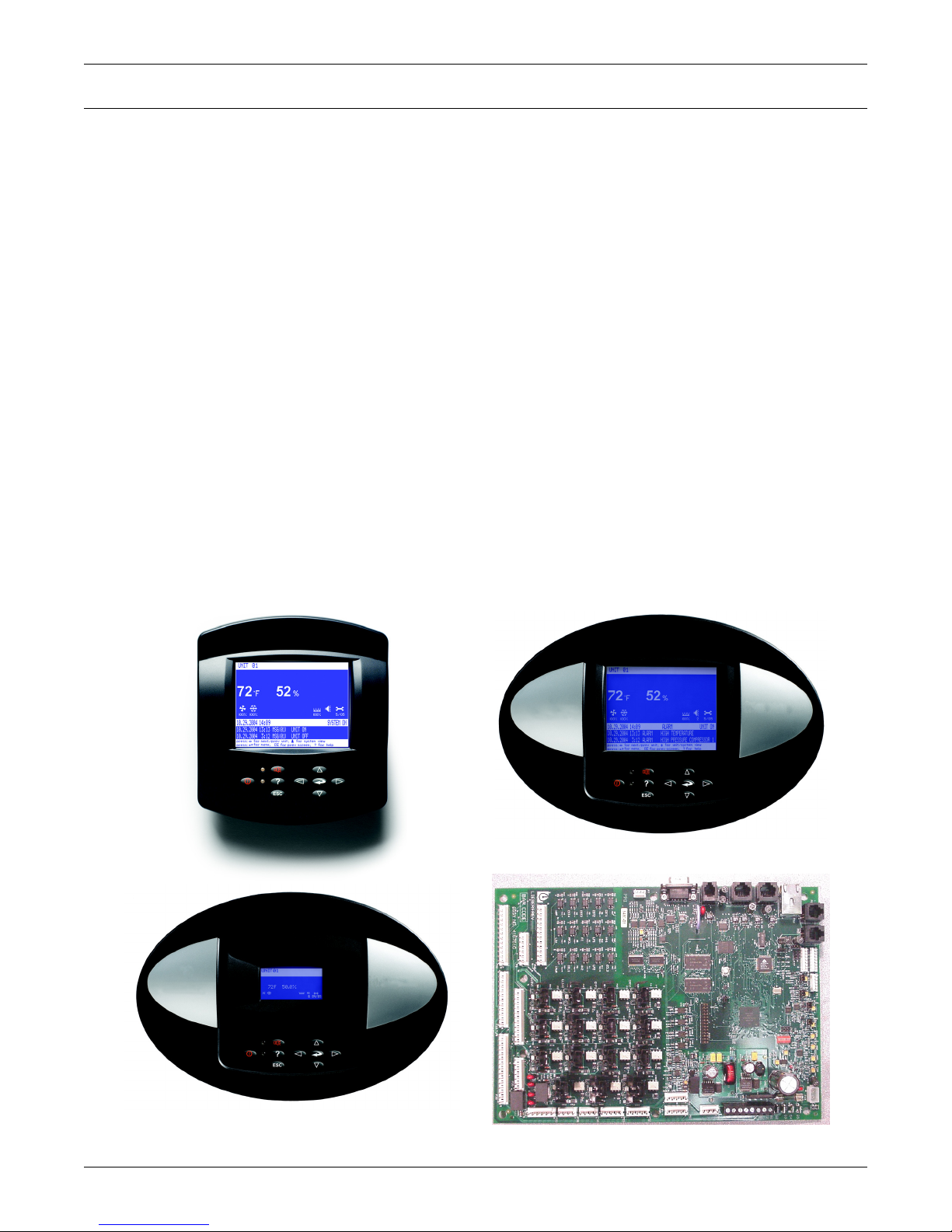
Wall Mount Large Display
Direct Panel Mount
Small Display and Bezel
Direct Panel Mount Large Display and Bezel
Liebert iCOM Input/Output Board
The Liebert iCOM® control offers the highest capabilities in unit control, communication and monitoring of Liebert mission-critical cooling units.
Liebert iCOM may be used to combine multiple cooling units into a team that operates as a single
entity, enhancing the already-high performance and efficiency of Liebert’s units.
Liebert iCOM is available as a factory-installed assembly or may be retrofitted on existing products
with SM, AM or AG controls. Large graphic display wall-mount versions of the control are available
for remote operation and monitoring of cooling units.
1.1 Features
Large and Small Displays
The Liebert iCOM control is available with either a large or small liquid crystal display.
•The Liebert iCOM with small display has a 128 x 64 dot matrix screen that simultaneously
shows two menu icons, along with descriptive text. This display is capable of controlling only the
unit it is directly connected to.
•The Liebert iCOM with large display has a 320 x 240 dot matrix screen that shows up to 16
menu icons at a time, as well as descriptive text. This display can be used to control a single cooling unit or any cooling unit on a network, regardless of how it is connected—either integrated into
a cooling unit or simply connected to the network and mounted remotely.
Introduction
Liebert iCOM’s menu-driven display is used for all programming functions on each connected cooling
unit. The Status menu shows the status of the conditioned space, such as room temperature and
humidity, temperature and humidity setpoints, alarm status and settings, event histories and the
current time.
Figure 1 Liebert iCOM components
1
Page 8
Liebert iCOM Display Components and Functions
ESC
?
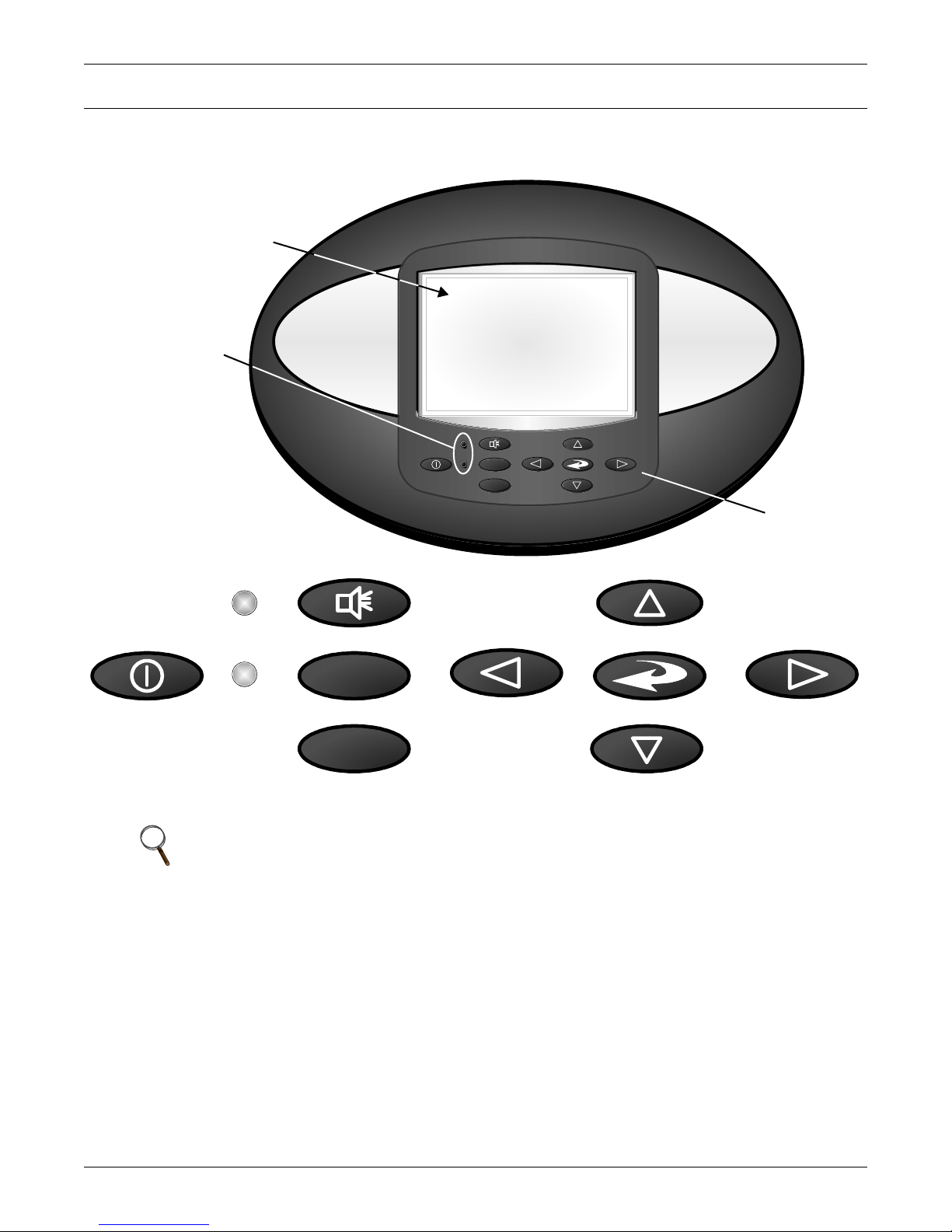
Liquid Crystal Display
Keypad
Large Liebert iCOM Display
shown - Keypad and LEDs are
identical on all displays.
LED Status Indicators
(top LED is red or
flashing red; bottom
LED is green or amber)
ESC
?
On/Off Key
Escape Key Down Arrow Key
Up Arrow Key
Left Arrow Key Right Arrow KeyEnter Key
Alarm Key
Help Key
2.0 LIEBERT ICOM DISPLAY COMPONENTS AND FUNCTIONS
The small and the large display have a common key layout, as shown in Figure 2.
Figure 2 Liebert iCOM display components
NOTE
The Help key may be pressed at any time for a brief explanation of what is being viewed.
2
Page 9
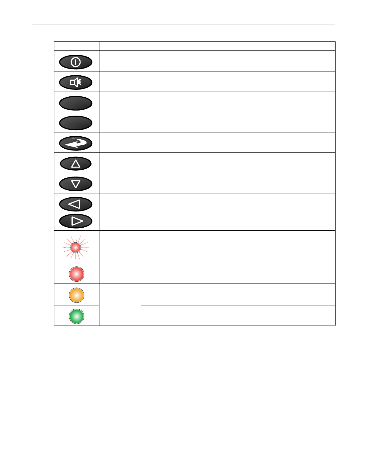
Table 1 Keyboard icons and functions
?
ESC
Icon Key Name Function
On/Off Key Controls the operational state of the cooling unit.
Alarm Key Silences an alarm.
Help Key Accesses integrated help menus.
ESCape Key Returns to the previous display view.
Enter Key Confirms all selections and selects icons or text.
Liebert iCOM Display Components and Functions
Increase Key
(Up Arrow)
Decrease Key
(Down Arrow)
Left and Right
Arrow Keys
Upper LED
Lower LED
Moves upward in a menu or increases the value of a selected parameter.
Moves downward in a menu or reduces the value of a selected parameter.
Navigates through text and sections of the display.
Blinking Red—Active, unacknowledged alarm exists
Solid Red—Active, acknowledged alarm exists
Amber—Power is available to the unit, unit is NOT operating
Green—Power is available to the unit, unit is operating
3
Page 10
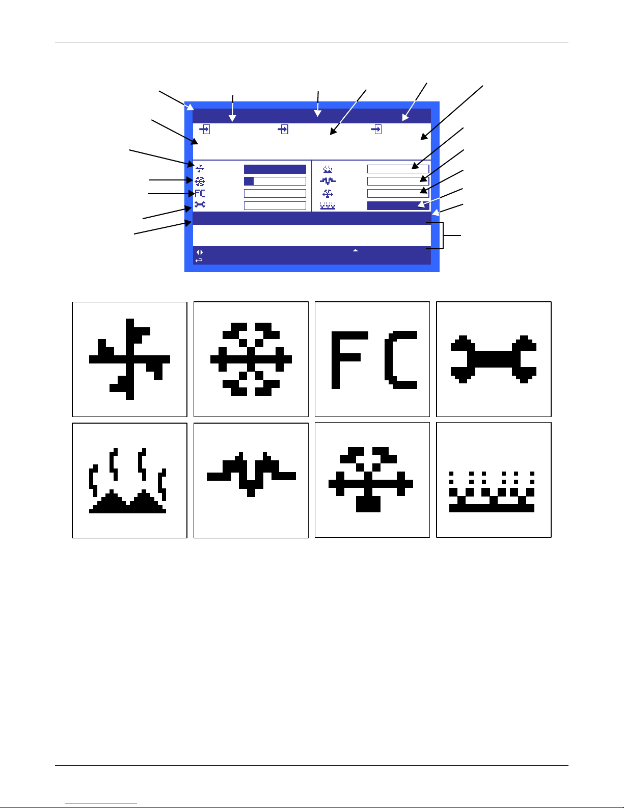
Figure 3 Status menu, large display, graphical view
UNIT 1
11/ 11/2009 8 : 31 MSG UNIT ON
11/ 11/2009 8 : 30 MSG UNIT ON
11/ 11 /2009 09 :18 :07
ESC
for previous screen ? for help
UNIT ON
for system view
for ne xt/pr eviou s unit
for menu
48
%
51.1
°F
ACT
72.9
°F
73. 4°F 50% 50.9 °F
100%
14%
0%
12/2011
0%
0%
0%
0%
SET
Evaporator
Fan Speed
Temperature
Setpoint
Humidity
Setpoint
Humidity
Sensor
Reading
Supply Air
Temperature
(optional)
Percent Hot Water
Heating
Percent Electric
Heating
Percent Dehumidifying
Percent Humidifying
System (or Unit) On/Off
Most Recent Alarms
(Date, Time, Unit,
Description)
System or
Unit # view
Temperature Sensor
Reading
Percent Cooling
Free-Cooling
Percentage
Next Maintenance
Date and Time
Supply Air
Setpoint
fan
cooling
maintenance
hot water
electric heat
dehumidification humidification
freecooling
Figure 4 Liebert iCOM default screen symbols
Liebert iCOM Display Components and Functions
4
Page 11
2.1 Navigating Through the Liebert iCOM Menus
Status Menu
Unit 1 View
User Menu
Password
Setpoints
Event Log
Graphics
Set Alarms
Sensor Data
Active Alarms
Display Setup
Total Run Hours
Sleep Mode
iCOM-DO
Service Info
Service Menu
Password
Setpoints
Standby Settings/Lead-Lag
Maintenance/Wellness Settings
Diagnostics/Service Mode
Set Alarms
Sensor Calibration/Setup
Options Setup
iCOM-DO
Service Contact Info
Advanced Menu
Password
Factory Settings
Access Passwords
Liebert iCOM shows icons and text for monitoring and controlling your Liebert cooling units or network of cooling units. The number of icons and amount of text shown depends on the display size.
2.1.1 Control Interface
When the buttons on the Liebert iCOM control have not been pressed for a short period, the display
backlight turns off. Pressing any key will turn the backlight on (wake up the screen) and display the
Status menu of the last cooling unit viewed. The Status menu will show the cooling unit’s operational
mode(s), return air temperature and humidity readings, temperature and humidity setpoints and any
active alarm conditions.
If the cooling unit has a large display and is not on a network, or if the unit has a small display,
whether it is networked or stand-alone, the Status menu will display only that cooling unit’s information. Any large display that is connected to a network can be used to view any cooling unit on the network or show an average view of the entire system of cooling units.
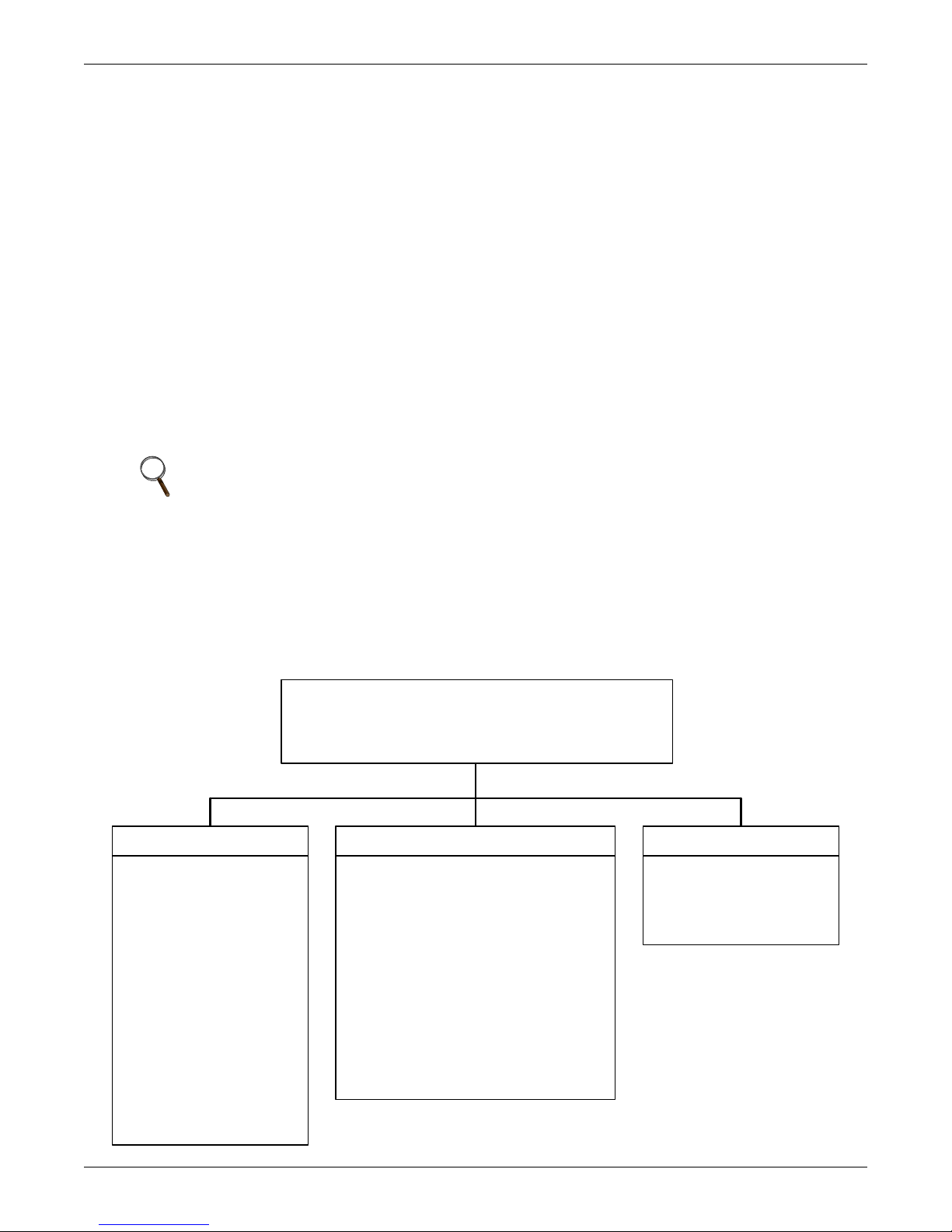
The Liebert iCOM control has three main menus; User, Service and Advanced.
The User menu contains the most frequently used features, settings and status information. The Service menu contains settings and features used to set up unit communications and for unit maintenance. The Advanced menu contains settings used to set up the unit at the factory.
NOTE
Menu settings may be viewed without a password, but changing settings requires a password.
If a password is required, Liebert iCOM shows a prompt to enter the password. The password
for the User menu is 1490. The password for Service menu is 5010. For details on entering a
password, see Entering a Password on page 6
Liebert iCOM Display Components and Functions
2.1.2 Accessing Submenus
To access the User, Service or Advanced menu, press the Enter or down arrow key while viewing the
Status menu of the unit you wish to access. The User menu will be displayed first. To view the Service
or Advanced menus, press the right arrow key.
Figure 5 Menu tree—Small display, stand-alone or networked
5
Page 12

Liebert iCOM Display Components and Functions
Accessing Submenus on Small Displays
While viewing the menu you wish to access (User, Service or Advanced), use the up and down arrow
keys to scroll through the icons page-by-page. To scroll through the icons one-by-one, press the enter
key and then use the up and down arrow keys. With the desired icon highlighted, press the enter key
to enter that submenu. Once in a Submenu, a list of parameters is displayed.
Press the enter key and use the up and down arrow keys to scroll through the parameters one-by-one.
Pressing the Esc key will go back a level. Figure 5 shows the Liebert iCOM control menus for a small
display.
Accessing Submenus on Large Displays
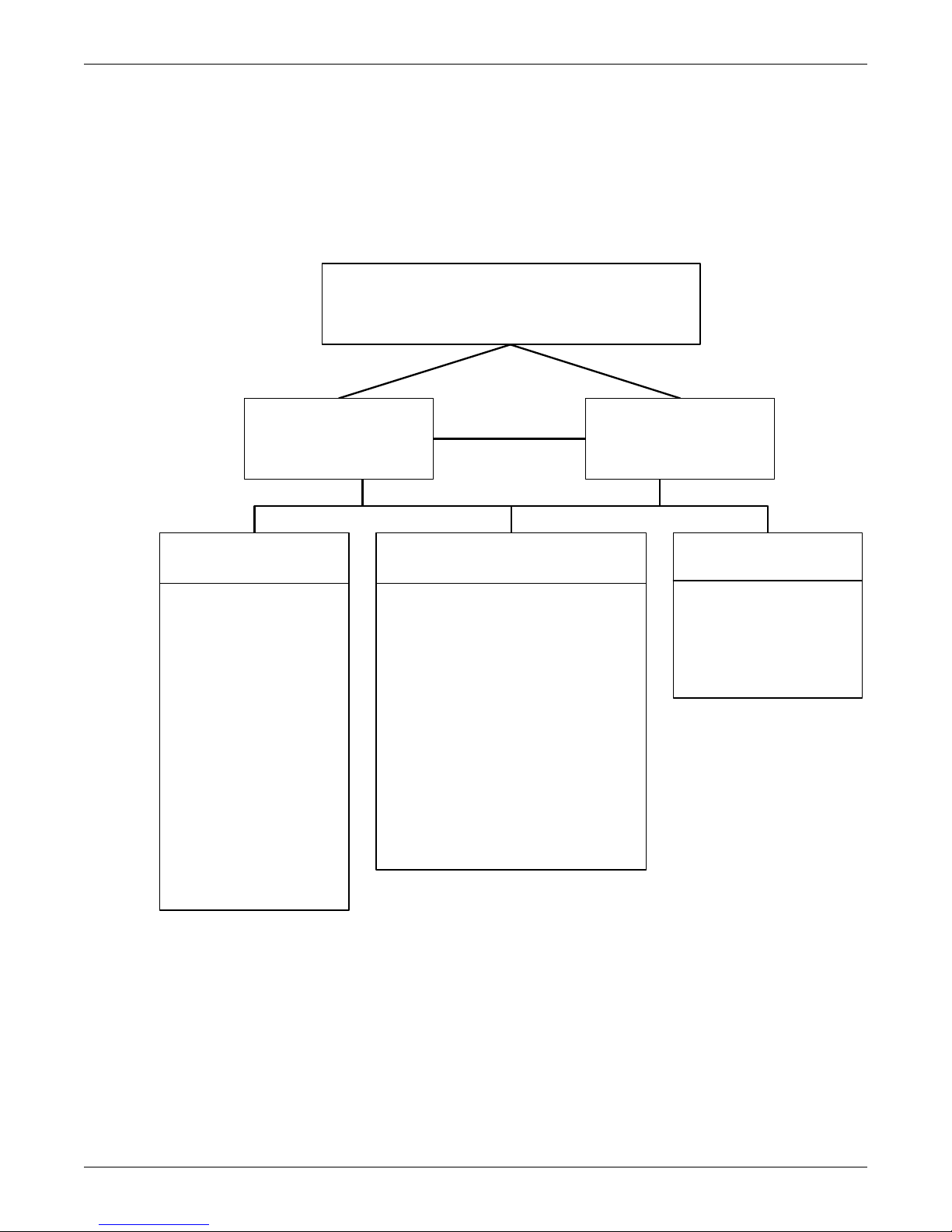
While viewing the menu you wish to access (User, Service or Advanced), press the enter key to highlight the first icon. Use the arrow keys to navigate through the icons. With the desired icon highlighted, press the enter key to enter that submenu. Once in a Submenu, a list of parameters will be
displayed.
The up and down arrow keys may be used to scroll through the parameters page-by-page if the submenu has multiple pages. To scroll item-by-item, press the Enter key and then use the up and down
arrow keys. Using the right or left arrow keys on large displays attached to a network will change the
unit being viewed. Pressing the Esc key will go back a level. Figures 7 and 8 show the Liebert iCOM
control menus for a stand-alone large display and for a networked large display, respectively.
NOTE
Settings are readable without a password, but changing settings requires a password.
2.1.3 Entering a Password
To change the value of a parameter in a menu, you must first enter the password for that menu. The
User, Service and Advanced menus each has a unique password to prevent unauthorized changes.
The User menu password is 1490; the Service menu password is 5010.
NOTE
Entering the Service menu password permits access to both the User and Service menus.
To enter a password:
1. Navigate to the menu that contains the parameter to be changed.
2. Select Password in the submenu by pressing the Enter key
3. Press the Enter key to move your cursor to the right side of the screen to select the question
marks.
4. Use the arrow keys to enter the numeral for the password’s first digit (the up arrow key moves
from 1 to the next digit).
5. Use the right arrow key to move to the next question mark and repeat Step 4 to enter all digits in
the password.
6. After entering the password, press enter.
If the password is correct, the Actual Level shown to the right of Password will change
from 0 to 1 or 2. The menu will remain locked if the password was incorrect.
NOTE
Returning to the Status menu will require re-entering a password to make changes.
6
Page 13
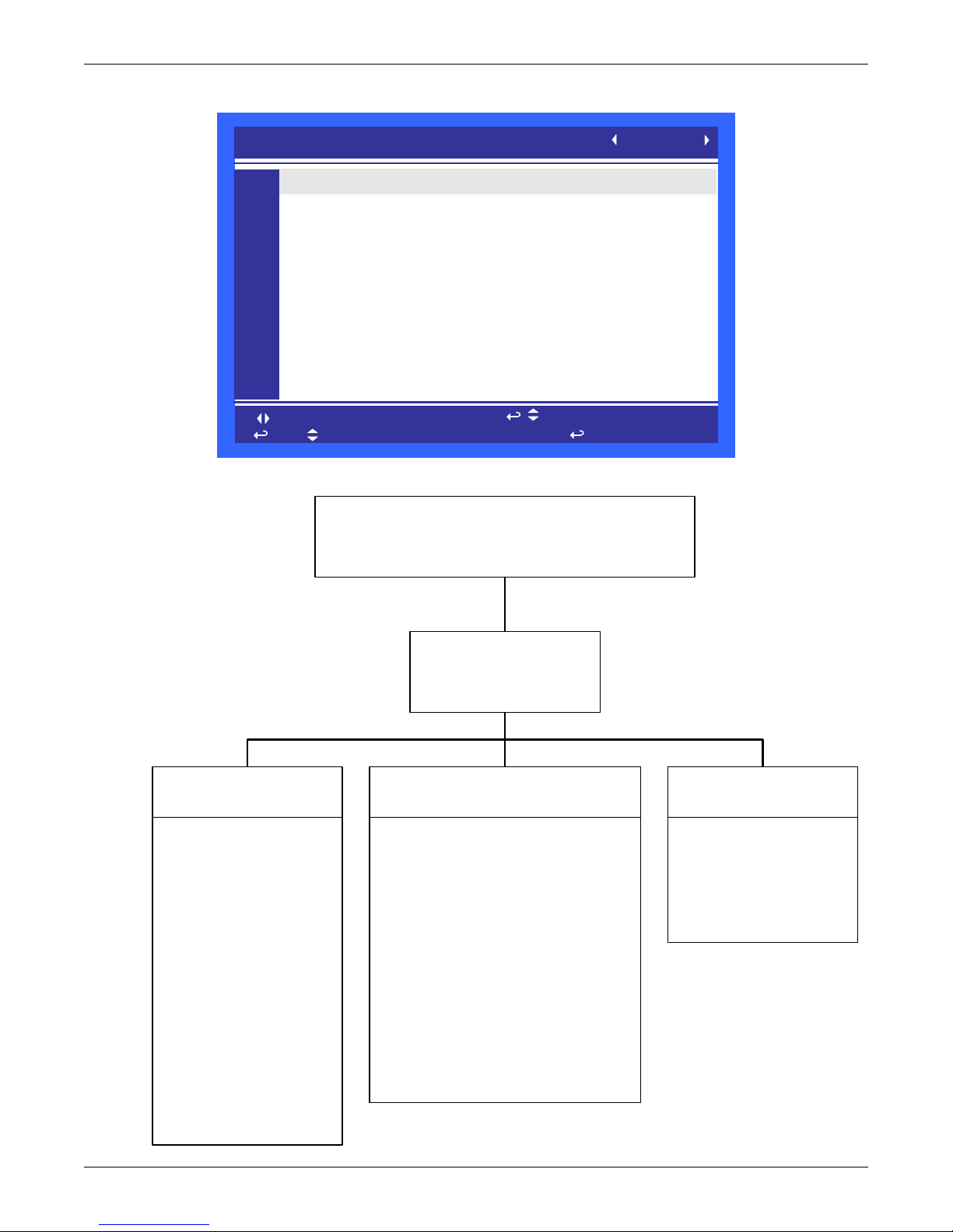
Figure 6 Entering a password
SETPOINTS
to change parameter
to confirm
to select parameter
for next/previous unit
then
PASSWORD (Actual Level 0)
Temperature Setpoint
Humidity Setpoint
Humidity Control Type
Supply Sensor
Supply Setpoint
Backup Temperature Setpoint
????
73°F
50.0%
Relative
Control
50°F
73°F
UNIT 01
U101
U102
U103
U104
U105
U106
U107
U108
U109
U110
U111
Status Menu – System View
Status Menu
Unit 1 View
User Menu
Unit 1
Password
Setpoints
Spare Part List
Event Log
Graphics
View Network
Set Alarms
Sensor Data
Active Alarms
Display Setup
Total Run Hours
Sleep Mode
iCOM-DO
Service Contact Info
Service Menu
Unit 1
Password
Setpoints
Unit Diary
Standby Settings/Lead-Lag
Maintenance/Wellness Settings
Diagnostics / Service Mode
Set Alarms
Sensor Calibration/Setup
System/Network Setup
Options Setup
iCOM-DO
Service Contact Info
Advanced Menu
Unit 1
Password
Factory Settings
Compressor Info
Access Passwords
Unit 1 will be displayed
in the top left corner of
the screen.
Figure 7 Menu tree—Large display, stand-alone
Liebert iCOM Display Components and Functions
7
Page 14
Liebert iCOM Display Components and Functions
Status Menu – System View
(Networked Large Display Only)
Status Menu
Unit 1 View
Status Menu
Unit 2, 3, 4...
User Menu
Unit #
Password
Setpoints
Spare Part List
Event Log
Graphics
View Network
Set Alarms
Sensor Data
Active Alarms
Display Setup
Total Run Hours
Sleep Mode
iCOM-DO
Service Contact Info
Service Menu
Unit #
Password
Setpoints
Unit Diary
Standby Settings/Lead-Lag
Maintenance/Wellness Settings
Diagnostics / Service Mode
Set Alarms
Sensor Calibration/Setup
System/Network Setup
Options Setup
iCOM-DO
Service Contact Info
Advanced Menu
Unit #
Password
Factory Settings
Compressor Info
Access Passwords
Unit # or System will be
displayed in the top left
corner of the screen .
2.1.4 Viewing Multiple Units with a Networked Large Display
When you first wake up the control, press the Esc key to return to the System view Status menu. This
view shows an average of all the units on the network and any alarms present. To view a specific unit
on the network, press either the enter key or down arrow key. When you do this, you will see the word
System in the top left of the screen change to a unit number. Using the left and right arrow keys you
can toggle through the various units on the network. To go back to the System view, or back one level
from any menu in the control, press the Esc key.
Figure 8 Menu tree—Large display, networked
8
Page 15
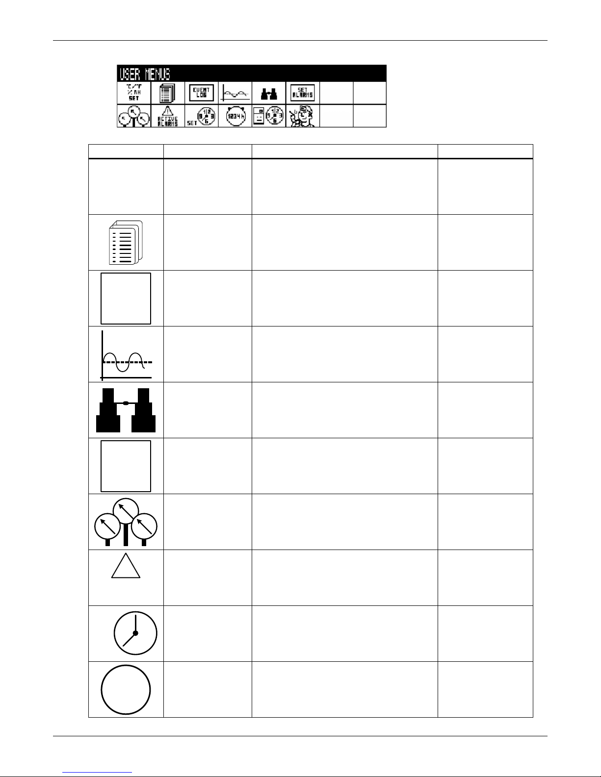
Figure 9 User menu icons
User Menu password: 1490
°C / °F
% RH
SET
EVENT
LOG
SET
ALARMS
!
ACTIVE
ALARMS
1 2
39
6
SET
1234h
Table 2 User menu icons
Icon Name
Description
Liebert iCOM Display Components and Functions
Available On Display
Setpoints
Spare Part List
Event Log Contains last 400 events Small & Large
Graphics Displays temperature and humidity graphs Small & Large
View Network Shows status of all connected units Large
Set Alarms Allows enable, disable and settings for alarms Small & Large
View and change temperature and humidity
setpoints
Displays the various part numbers of the
components/parts in the cooling unit
Small & Large
Large
Sensor Data
Active Alarms
Display Setup
Total Run Hours
Shows readings of standard and optional
sensors
Allows the user to view all current active
alarms
Change settings for display: language, time,
simple or graphic view
Records the run time of all components and
allows setting of limits on run time
9
Small & Large
Small & Large
Small & Large
Small & Large
Page 16
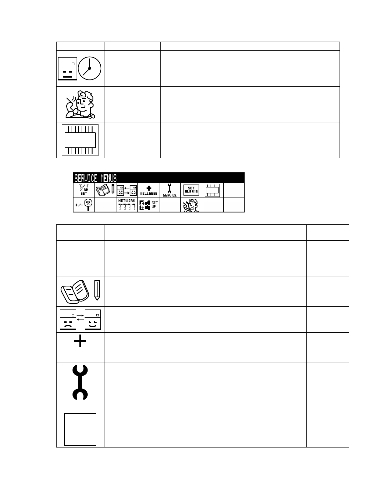
Table 2 User menu icons (continued)
1 2
39
6
DO
Service Menu password: 5010
DO
°C / °F
% RH
SET
WELLNESS
SERVICE
SET
ALARMS
Icon Name
Description
Liebert iCOM Display Components and Functions
Available On Display
Sleep Mode
Service Contact Info
iCOM-DO
Figure 10 Service menu icons
Table 3 Service menu icons
Icon Name
Allows setback settings for non-peak
operation
Contains key contact information for local
service, including names and phone numbers
Change settings for Liebert iCOM Discrete
Output card
Description
Small & Large
Small & Large
Small & Large
Available On
Display
Setpoints To view and change temperature and humidity setpoints Small & large
Unit Diary
Standby Settings/
Lead-Lag
Maintenance/
Wellness Settings
Diagnostics/
Service Mode
Set Alarms Allows enable, disable and settings for alarms Small & large
Shows all entered program changes and maintenance
performed on the unit
Allows lead/lag setup when multiple units are connected Small & large
Allows setting maintenance interval reminder,
maintenance message, number of unit starts and stops,
and time since last maintenance
Allows troubleshooting, manual mode, read analog and
digital inputs
Large
Small & large
Small & large
10
Page 17
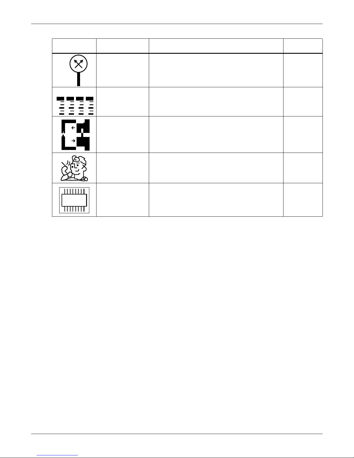
Table 3 Service menu icons (continued)
+ / -
NETWORK
DO
Icon Name
Description
Liebert iCOM Display Components and Functions
Available On
Display
Sensor
Calibration/Setup
System/Network
Setup
Options Setup Allows setup of component operation Small & large
Service Contact Info
iCOM-DO Change settings for Liebert iCOM Discrete Output card Small & Large
Allows calibration of sensors Small & large
Allows setup and U2U communication for multiple units Large
Contains key contact information for local service,
including names and phone numbers
Small & large
11
Page 18

3.0 OPERATION
Remote On / Off
Display On / Off
The Liebert iCOM display provides viewing, trending and configuration capability for Liebert cooling
units. All unit settings and parameters can be viewed and adjusted through three menus: User, Service and Advanced. All active alarms are displayed on the LCD and annunciated.
The control is shipped from the factory with default selections for all necessary settings. Adjustments
can be made if the defaults do not meet your requirements.
References to menu items in this manual are followed by the main menu and the submenu where they
can be found.
For example:
• Temperature Setpoint (User Menu, Setpoints) - The Temperature Setpoint parameter is
located in the User menu under the Setpoints submenu.
• High Return Humidity (Service Menu, Set Alarms) - The High Return Humidity alarm is
located in the Service menu under the Set Alarms submenu.
3.1 Single Unit Functions
3.1.1 Unit/Fan Control
Start - Stop
Unit on means the fan output is activated. The unit can be switched On and Off from two inputs:
• Remote Off - Remote shutdown terminals will turn off the connected unit thus displaying remote
off on the front display. This command can also be invoked from a BMS.
• Display Off - When a unit is turned off from the System Screen of a large display, Display OFF is
shown for unit status.
• Local OFF - When a unit is turned off from the Unit Status Screen or small display, Local OFF is
shown for unit status.
Pressing the On/Off key on a small display will control only the cooling unit it is connected to regardless, of whether the cooling unit is a stand-alone unit or part of a network.
Operation
NOTE
Pressing the On/Off key on a large display of a stand-alone cooling unit will control
only that unit.
The effect of pressing the On/Off key on a large display connected to a network depends on the view:
System or Unit.
• In System view, pressing the On/Off key shows a warning asking for confirmation to shut down
the entire system.
• In Unit view, pressing the On/Off key affects only the unit being viewed, without a confirmation
request.
Each time a unit is powered on or off, an event is added to the Event Log in the User menu.
NOTE
Customer switches: remote On/Off (if used) and display On/Off switches are in series. A
cooling unit will start only if both switches are On; if one of these switches is Off, the unit will
stop. Safety devices within the unit are also in series and will shut the unit down if required.
Figure 11 Start-stop priority switches
NOTE
If Remote On/Off is not used, a jumper is inserted to bypass the switch.
12
Page 19

Operation
Autorestart
When there is a loss of power to the cooling unit and power comes back, the unit will return to its previous operating status—on if it was on before the power off, off if it was off.
When power returns, the autorestart time—time-selectable: Single Unit Auto Restart (Service Menu,
Options Setup)—controls the start of the unit. If the units are on the same network, the autorestart
time runs in a loop, starting each unit in sequence, starting with Unit # 1.
Loss of Power Alarm
A Loss of Power Alarm is activated when power is restored after an interruption. If acknowledged, the
alarm resets automatically after 30 minutes. This alarm can be set to different event types (Message,
Alarm or Warning) and can be disabled under menu item Loss of Power (Service Menu, Set Alarms).
NOTE
Loss of Power alarm will be activated only on units that had the fan switched On before power
was lost.
Fan Alarm / Fan Protection Settings
The fan operation is protected by two digital devices: motor protection (optional) and a differential
pressure switch. The motor protection monitors for main fan overload (Main Fan Overload alarm) and
the differential pressure switch ensures that the blower(s) are moving air (Loss of Airflow alarm). If
either protection device is actuated after an adjustable time delay, an audible alarm occurs, an alarm
relay ativates and an event is recorded in the event log (Main Fan Overload and Loss of Airflow in
Service Menu, Set Alarms).
The fan delay at the unit start is always five seconds shorter than the control delay (to avoid shortcycling components when the fan is not working).
There are two selection possibilities for both, Loss of Airflow and Main Fan Overload:
• Shutdown—stops the unit (intended for DX models).
• Disable—stops the humidifier, electrical heaters and dehumidification; allows cooling and
free-cooling only (intended for chilled water models / external cooling).
NOTE
When the Main Fan Overload alarm is active, the Loss of Airflow alarm is masked out.
13
Page 20

Operation
Chilled Water Units with Variable Fan Speed—EC or Variable Frequency Drives
VSD Fan Speed parameter can be found in the Service Menu / Setpoints submenu on page 5 of 6. This
menu allows the cooling unit's fan motor speed to be configured and adjusted for a variety of applications.
• Auto Operation: When set to Auto, the speed of the fan motor follows the position of the chilled
water valve based on predetermined logic for cooling and dehumidification operation. Auto operation can be set with either return or supply air control.
• Manual Operation: When set to Manual, the speed of the fan motor follows user input as set
either locally at the Liebert iCOM display or remotely via a Modbus signal with an optional Liebert IntelliSlot® 485 card.
• Economy Operation (GLYCOOL or dual-cool units only): When set to Economy, the speed of the
fan motor follows the Free Cooling or Dual Cool water valve. The fan speed will go to the STD setpoint (Service Menu, Setpoints) when a compressor activates to prevent pre-cooling of the DX coil.
• Delta Operation: When set to Delta, the speed of the fan motor is controlled by two temperature
sensors (optional). The sensor temperature readings will be compared and a delta between the
two sensors will be determined. The delta of the two sensors will be compared to the fan speed
delta setpoint and will determine the correct fan speed. This control can be adjusted using the
Fan Speed P-Band and the Fan Speed Integration to determine the rate of change based on the
sensor delta. Delta operation enhances air flow control when a containment solution is being utilized. This is accomplished by maintaining the correct airflow based on the inner and outer containment temperatures.
• Return Operation: When set to Return, the speed of the fan motor is controlled by the return air
sensor and the cooling capacity is controlled from the supply sensor (optional). This allows the
return air sensor to be left in the return air of the unit or placed remotely. If placed remotely
make sure that the sensor is mounted with the connected unit's area of influence.
Additional fan speed configuration parameters include a fan speed filter and fan speed reposition
delay timer. These parameters allow the fine tuning of the fan speed control and can be applied to any
control mode except Manual.
• The fan speed filter allows the fan to react differently depending on the location of the control
point within the proportional band.
Example: When the temperature is close to setpoint or lower in the proportional band the fan
speed changes are slow to avoid overshooting the setpoint. However, when the temperature is further away from setpoint or higher in the proportional band the control will respond quickly.
• The fan speed reposition delay timer can be adjusted to prevent the fans from oscillating. This
delay timer will only allow the fan speed to decrease when the timer expires. Increases in fan
speed are not limited by this delay.
NOTE
• The fan speed lower and upper limit settings are defaulted to 60% and 100%. These
parameters can be adjusted to operate at any point between the default settings.
• The standard fan speed control will be overridden during a call for Dehumidification. When
there is a call for Dehumidification, the fan speed will change to the VSD Setpoint Dehum
parameter found in the Service Menu, Setpoints.
• The standard fan speed control will be overridden during a call for Humidification or
Reheat. During a call for Humidification or Reheat ,the fan speed will change to 100% to
eliminate the possibility of condensation or damage to the unit.
VSD Setpoint (VSD Fan Speed Setting)
If the VSD Fan Speed Control (Service Menu, Setpoints) is set for Manual, the VSD Fan Speed Setpoint (Service Menu, Setpoints) may be set for the desired speed of the variable speed motor.
Depending on the product control design, there may be an internal minimum speed, as defined by
that specific product operation, while the customer input may be set for 0-100%:
• Fan speed may be set locally at the unit using the Liebert iCOM display.
• Fan speed may be set remotely via a BMS signal (sent via Modbus using an optional Liebert IntelliSlot 485 card), which then transmits to the unit local control.
14
Page 21

3.1.2 General Compressor Requirements
Low-Pressure Time Delay
When the compressor starts, the low-pressure input is ignored for a selected period of time based on
the setting of the Low Pressure Alarm Delay (Service Menu, Options Setup). This time is usually set
to 3 minutes on air-cooled units, and to 0 or 1 minute on water cooled units. When this time is
expired, a second timer starts to operate if the low-pressure input is active. This second timer is active
during normal compressor operation to avoid compressor trips due to bubbles in the refrigerant or
other influences creating short trips of the low-pressure switch. The low-pressure switch input is
enabled only if the compressor is operating. Exception: Pump Down (see Pump Down).
NOTE
Low-pressure condition could be read through contacts or through pressure transducers with
threshold setting.
Pump Down
The Pump Down operation is performed to protect the compressor oil from being diluted with liquid
refrigerant to ensure that the compressor is properly lubricated for the next startup. The Pump Down
operation operates in the following manner:
Whenever the control determines that no more cooling is required and a compressor needs to be shut
off, the liquid line solenoid valve (LLSV) is closed (de-energized). The compressor will continue to
operate until the low suction pressure switch (LPS) opens, which shuts off the compressor. If the LPS
does not open within a specified time, the LLSV is turned On, then back Off (the assumption is that
the LLSV is stuck). If, after three times, , the LPS does not open, the compressor and LLSV are locked
off and an alarm “Pump Down not completed” will appear.
Operation
There is a re-pump down if the LPS opens again after the compressor has been already stopped—a
maximum of six re-pump-down cycles per hour are allowed. At the seventh request of re-pump down
the alarm “Comp 1 Pumpdown Fail” or “Comp 2 Pumpdown Fail” will appear and the compressor will
be locked out.
Pump down is always performed loaded (for compressors with unloaders: unloaders off, digital scroll:
control solenoid valve disabled).
For digital scroll only: when pump down has finished successfully (LPS opened), pump down will be
continued for another half-second with the control solenoid valve energized.
High Pressure Alarm
When the compressor is initially activated, the system will be monitored for a high pressure situation.
When a high pressure situation is detected during the first 10 minutes of operation, the unit will
attempt to correct the problem several times without notification. If the unit is unsuccessful in correcting the problem, an alarm will occur and the affected compressor will be locked off. If high head
pressure alarm trips three times in a rolling 12 hour period, the affected compressor will be locked off.
After the compressor has been running for 10 minutes, if a high head pressure situation is detected,
an alarm will occur and the affected compressor will be immediately locked off without the unit trying
to correct the problem.
Once the compressor is locked off, it will not come back on until main power is reset, or until the
HP Alarm Counters (Service Menu, Diagnostics) are reset to 0. Setting the counter to 0 will auto-reset
the alarm without the need of pressing the reset button on the display. Even if the pressure in the
system drops below the alarm point, the compressor will remain off until the system is reset.
NOTE
If the unit is equipped with manual reset high head pressure switches, or if the auto reset high
head pressure switches don’t reset, the compressor will not be turned back on, but there will be
a 30-second delay from when the high head pressure situation occurs and when the alarm is
annunciated.
15
Page 22

Digital Scroll High Temperature
A protective maximum operating compressor temperature limit is imposed on units with digital scroll
compressor(s) with thermistor. If the digital scroll temperature reaches the maximum temperature
threshold, the compressor will be locked out for at least 30 minutes and an alarm will be annunciated.
If after 30 minutes the temperature has cooled to a safe operating temperature, the compressor will
resume operation.
Each time a high-temperature alarm occurs, HT 1 Alarm Counter (Service Menu, Diagnostics) or
HT 2 Alarm Counter (Service Menu, Diagnostics) is increased by one. Once these counters reach five
occurrences in a rolling four-hour period, the compressor will be locked out. The alarm can be reset
once the temperature returns to a safe level by:
1. Setting the counter back to 0 from the display and pressing the alarm reset button.
2. Shutting off power to the control board by turning the cooling unit's main power disconnect switch
Off and On.
3.1.3 Compressor Timing—Short-Cycle Protection
To help maximize the life of your compressor(s), there is a start-to-next start delay for each single
compressor.
NOTE
This delay may cause a short cycle if there is a very light room load. A short cycle means that
the compressor has cycled On and Off 10 times in the past hour. Should this occur, contact
your local Emerson representative to adjust the minimum compressor off delay.
Operation
3.1.4 Compressor Sequencing on Two-Compressor Units
Compressor Sequencing parameter (Service Menu, Options Setup) is intended to maintain equal run
times between compressors. This setting has three selection possibilities:
• Always use Compressor 1 as lead compressor
• Always use Compressor 2 as lead compressor
•Auto:
• First priority: if the safety timings are acceptable for only one compressor, then it is the next
to be started/stopped.
• If both compressors are off: the one with fewer working hours is the next to start.
• If both compressors are in operation: the one that has been operating longer since the last
start is the next to be stopped.
NOTE
The Auto setting attempts to maintain equal run times between compressors.
3.1.5 Motorized Ball Valve in Digital Scroll Units
On water/glycol-cooled digital scroll units, discharge pressure is controlled by a motorized ball valve
(MBV). During unloaded operation, pressure changes during each digital cycle could cause a pressure-controlled water regulating valve to open and close an excessive number of times. The motorized
ball valve is designed to maintain a consistent peak discharge pressure.
The control algorithm for the motorized ball valve uses an intelligent sampling rate and adjustable
pressure thresholds to reduce the number of times the valve opens and closes. The valve assembly
consists of the brass valve, linkage and actuator.
Each compressor has one motorized ball valve that is driven by the analog output of the Liebert iCOM
control board based on discharge pressure. If there is a call for cooling, the compressor start is delayed
by a 30-second timer. During this delay, the motorized ball valve is set to 50% open to allow fluid flow
through the unit condenser. The compressor will start after the 30-second timer elapses.
Motorized Ball Valve Manual Mode: (Service/Service) Manual operation can be selected to allow
service personnel to control the motorized ball valve from the Liebert iCOM control.
16
Page 23

When Auto BV Control is selected, the motorized ball valve functions as it would be during normal
system operation.
NOTE
Compressor operation will be delayed 30 seconds to allow the motorized ball valve to position
itself for initial startup.
When Manual BV Control is selected, the user must be careful in setting the MBV position because
the ball valves will remain in the position set in the Service menu until the control is switched back to
Auto or until a technician changes the valves to another manual position (the motorized ball valve in
manual mode can be set in 1% increments from fully closed to fully open). Low- or high-discharge
pressure may occur during this mode, depending on environmental conditions and the position of the
motorized ball valve.
The motorized ball valve is driven by a 2-10VDC proportional control signal: the valve is closed at
2VDC, 50% open at 6VDC and fully open at 10 VDC.
3.1.6 MBV Operation After Compressor is Turned Off
Once a compressor has stopped, the MBV control will continue to change the MBV position to maintain system pressures for a maximum time of 10 minutes by following the auto BV control algorythm.
When the 10-minute delay has expired or the discharge pressure is below its minimum threshold the
motorized ball valve will close until the next compressor activation.
3.1.7 Service Offset—Changing System Pressure Settings
Operation
The MBV control is set to maintain a system pressure specific to the particular type of cooling unit. A
properly trained and qualified technician can increase or decrease the pressure through the Ball
Valve Setpoint Offset found in the Service/Options Setup menu. The range is 0 to 50 PSI; the default
is 30 PSI.
NOTE
Adjusting this parameter will increase or decrease the operating compressor discharge
pressure by changing the targeted range of control. The discharge pressure is the peak pressure
of the digital cycle.
17
Page 24
3.2 Temperature Control—Single Source Cooling (No Extra Cooling Coil)
0%
Setpoint
0%
Cooling
+ Temp
+ 100%
Cooling
½ Proportional Band
Dead -
band
-Temp
Heati ng
-100%
Heating
½ Proportional Band
CoolingHeati ng
-Temp + Temp
0%
Setpoint
+ 100%
Cooling
-100%
Heating
½ Proportional Band½ Proportional Band
With Deadband
Without Deadband
3.2.1 Temperature Proportional Band
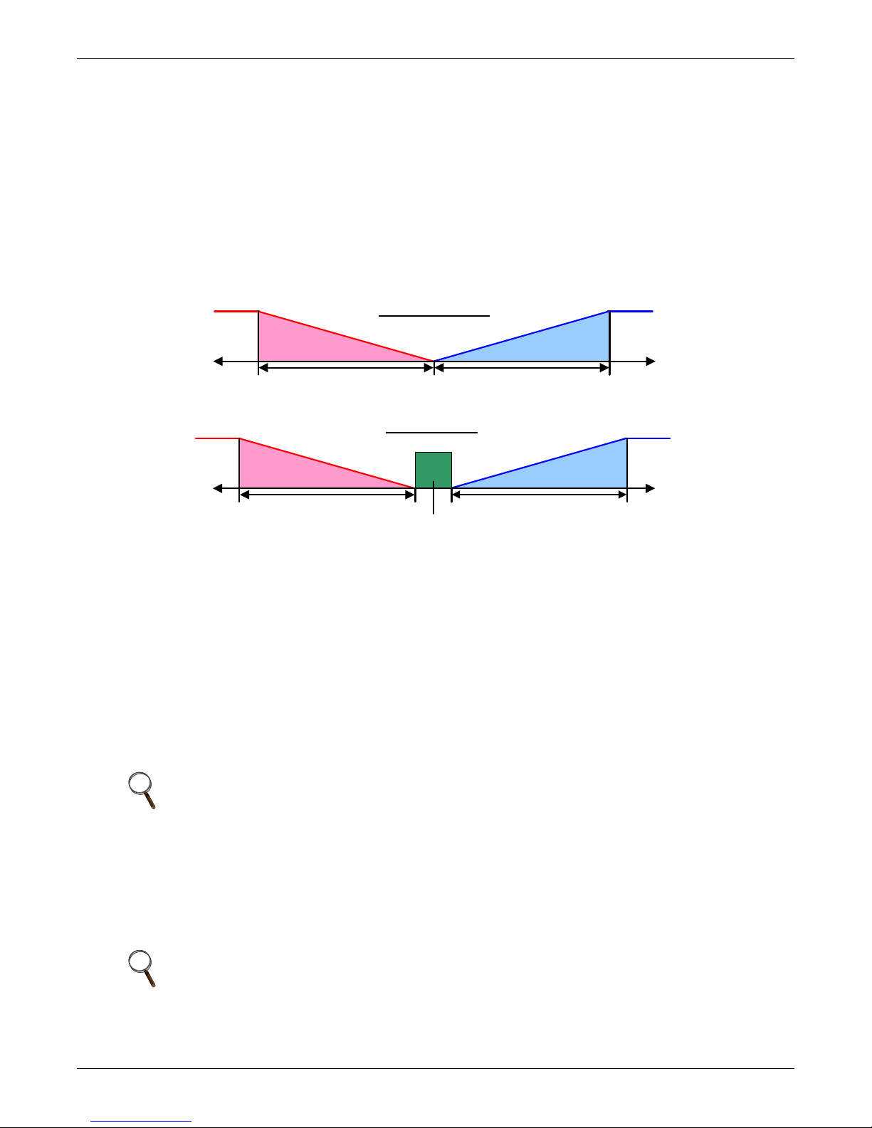
The control uses the temperature proportional band to determine which operation to perform (cooling/heating) and how much capacity to provide. The Temperature Proportional Band is a user-defined
range that is divided into two equal parts for cooling and heating. The Temperature Setpoint is
between these two equal parts.
An optional Temperature Deadband range can be defined, which is equally divided on either side of
the setpoint and separates the two halves of the proportional band. Figure 12 illustrates how the
temperature proportional band is evenly divided on either side of the temperature setpoint, with and
without a deadband.
Figure 12 Temperature proportional band
Operation
The control works the same for both supplyor return air control. When air temperature deviates from
the setpoint, the control will bring on cooling or heating. If the actual air temperature increases, the
control calls for 0% (none) to 100% (full) cooling capacity based on how much the temperature exceeds
the setpoint. If the return air temperature decreases, the control calls for 0% to -100% (none to full)
heating capacity based on how far the temperature is below the setpoint.
When the return air temperature reaches the end of the proportional band, either 100% or -100%, full
cooling or full heating capacity is provided. No operation is performed when a 0% call is calculated or
the temperature is within the deadband. The control varies the call for cooling and heating in 1%
increments as the air temperature moves through the proportional band halves.
The deadband range is used to widen the setpoint. When the air temperature falls within the deadband, the control operates the same as if the temperature equaled the setpoint exactly. This setting
helps maximize component life by preventing excessive component cycling.
NOTE
The temperature deadband prevents small temperature changes from activating compressors
and valves.
The Temperature Proportional Band and Temperature Deadband parameters are in the Service
menu under the Setpoints submenu. The Temperature Setpoint parameter is in both the User Menu
and Service Menu under Setpoints.
There is a parameter AutoSet Enable (Service Menu, Setpoints), which automatically sets the proportional bands for temperature and humidity, and both the integration time factors according to the
type of unit (chilled water, single or dual compressor).
NOTE
Before the proportional or integral setpoints can be changed, the Auto Set Enable must be
changed to NO.
18
Page 25
3.2.2 Compressor Control
Temp Setpoint : 70°F
Proportional Band: 8°F
Deadband: 2°F
75
½ Proportional Band
0%
Cooling
+ 100 %
Cooling
71 72 73 7470
½ Dead-
band
Cool 1
Off
Cool 1
On
Increasing Tem perature
Temp Setpoint: 70°F
Proportional Band: 8°F
Deadband : 2°F
75
1/2 Proportional Band
0%
Cooling
+ 100%
Cooling
71 72 73 7470
1/2 D ead -
band
Cool 1
On
Cool 2
On
Increasing Temperature
Cool 2
Off
Cool 1
Off
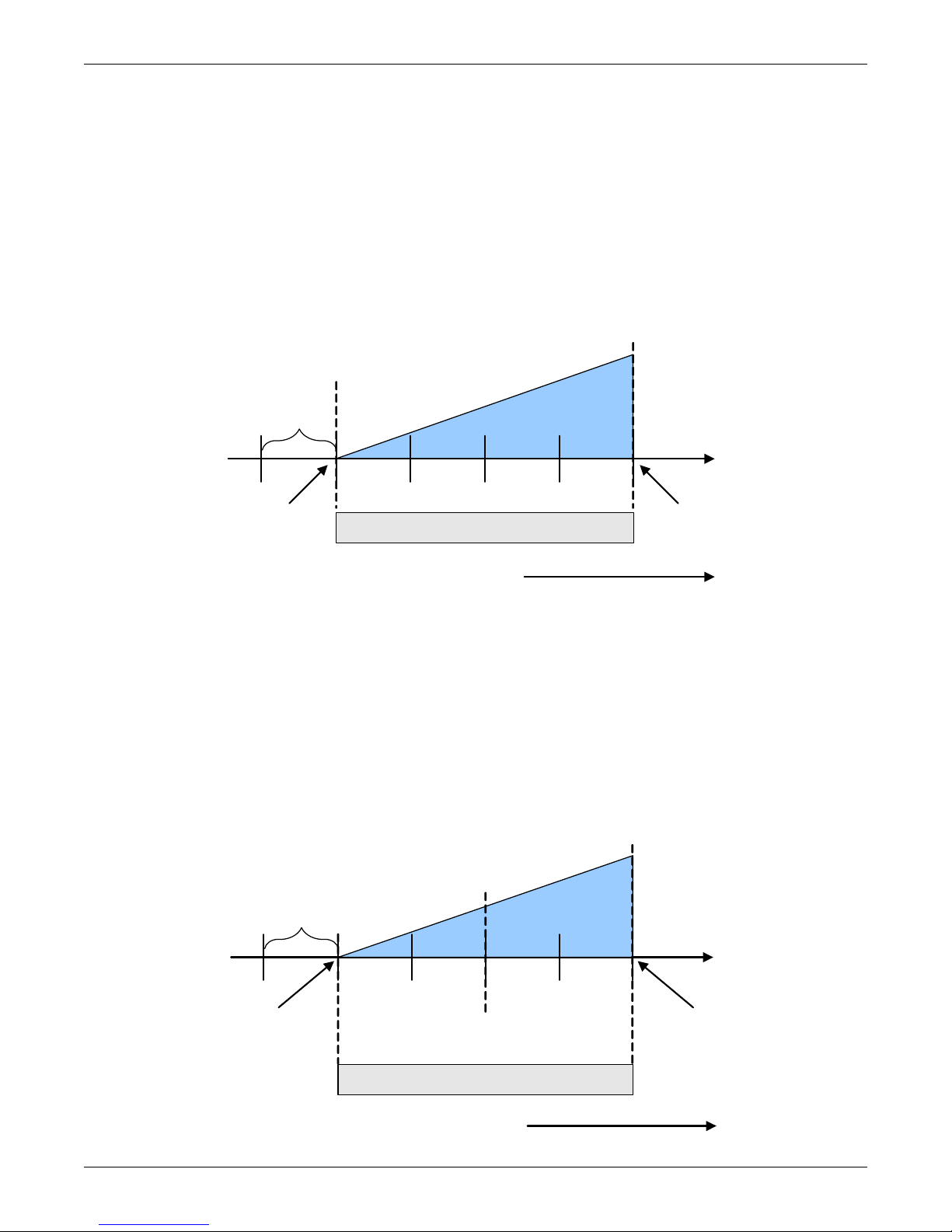
Depending on its type, a Liebert Precision Cooling unit may have one or two compressors with or
without unloaders or variable capacity.
Compressor Proportional Bands
One Single-Step Compressor Without Unloaders—One-Step
One single-step compressor, Cool 1, is started at 100% call for cooling from the temperature proportional band and stopped at 0% (see Figure 13).
Figure 13 One single-step compressor without unloaders
Operation
Two Single-Step Compressors Without Unloaders—Two-Step
First single-step compressor, Cool 1, is started at 50% calculated output from the temperature proportional band, and stopped at 0%. The second compressor, Cool 2, starts at 100% and stops at 50% (see
Figure 14).
One Compressor With an Unloader—Two-Step
The two-step compressor is started unloaded at 50%, Cool 1, calculated output from the temperature
proportional band and stopped at 0%. At 100% the compressor starts fully loaded, Cool 2, and returns
to unload operation at 50% (see Figure 14).
Figure 14 Two single-step compressors without unloaders or one compressor with an unloader (two-step)
19
Page 26
Two Compressors With Unloaders—Four-Step
Cool 2
On
Temp Setpoint: 70°F
Proportional Band: 8°F
Deadband : 2°F
½ Dead-
band
Increasing Tem perature
½ Proportional Band
757473727170
0%
Cooling
+ 100%
Cooling
Cool 4
Off
Cool 2
Off
Cool 1
Off
Cool 4
On
Cool 3
On
Cool 1
On
Cool 3
Off
Call for Cooling: 66%
100% Loaded
0% Loaded
Solenoid
De-energized
Solenoid
De-energized
Solenoid
Energized
0 5 10 15 20 25 30
Solenoid
Energized
15-Second Capacity
Modulation Cycle
15-Second Capaci ty
Modulation Cycle
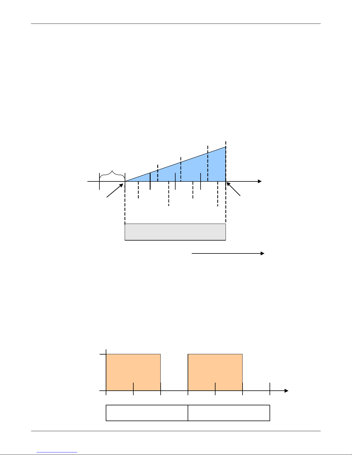
The first two-step compressor is started unloaded at 33% calculated output from the temperature proportional band and stopped at 17%. At 80% Compressor 1 will be loaded, at 70% unloaded.
The second compressor starts unloaded at 63% and stops at 47%. At 100%, Compressor 2 will be
loaded, at 90% unloaded (see Figure 15).
The four stages of cooling are accomplished in the following manner:
• 1 stage: One compressor, unloaded - Cool 1
• 2 stages: Both compressors, unloaded - Cool 2
• 3 stages: One compressor, loaded and one compressor, unloaded - Cool 3
• 4 stages: Both compressors, loaded - Cool 4
Figure 15 Two compressors with unloaders (four-step)
Operation
Digital Scroll Compressors
A digital scroll compressor can modulate its capacity anywhere between 10-100%. This variable
capacity modulation allows cooling units to control an environment more precisely.
Digital scroll capacity modulation is achieved by energizing and de-energizing a solenoid valve on the
compressor. When the solenoid valve is de-energized, the compressor capacity is 100%. When the solenoid valve is energized, the compressor capacity is zero. Therefore, the capacity of the compressor
depends on how long the solenoid is de-energized for. If the solenoid is de-energized for 10-seconds,
then energized for 5 seconds during a 15-second cycle, the resulting capacity will be 66% as shown in
Figure 16.
Figure 16 Digital scroll capacity modulation, 10-100% variable
20
Page 27
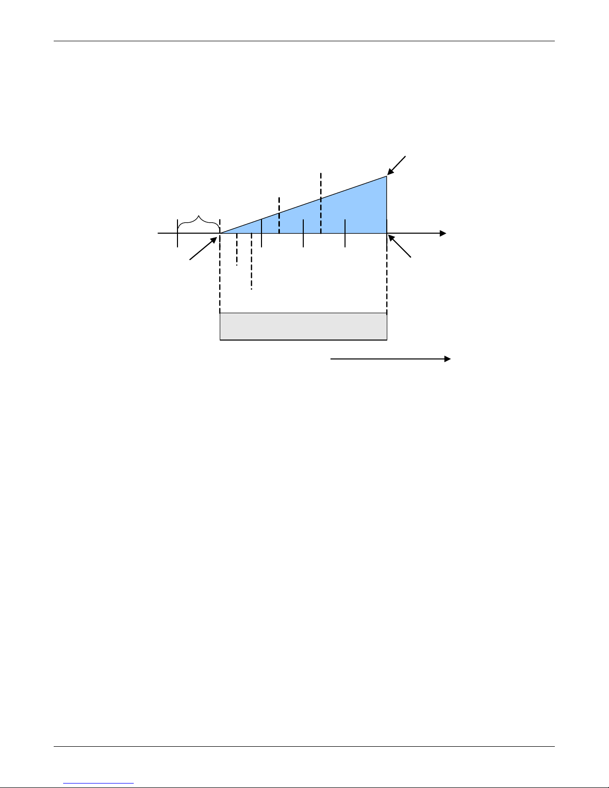
On single and dual digital scroll compressor systems, the first compressor is started at 25% calculated
Temp Setpoint: 70°F
Proportional Band : 8°F
Deadband: 2°F
½ Dead-
band
Increasing Tem perature
Comp 1
Off
½ Proportional Band
757473727170
0%
Cooling
+ 100 %
Cooling
Comp 2
Off
Comp 1 On Partially
Loaded
Comp 2 On Partially
Loaded
Comp 1 & 2 On
Fully Loaded
output from the temperature proportional band and stopped at 10%. On dual digital scroll compressor
systems, the second compressor is started at 35% and stopped at 20%, see Figure 17. When a compressor is started, the solenoid is energized longer than it is de-energized to match the call for cooling.
When the call for cooling increases to 100%, the solenoid is de-energized for the entire 15 second cycle.
Figure 17 Single and dual digital scroll compressor activation points
Operation
21
Page 28
3.2.3 Chilled Water Control
The chilled water control valve is adjusted proportionally as the temperature control varies the
requirement for cooling from 0% to 100%. A three-point actuator or motorized ball valve is used for
chilled water cooling, as well as free-cooling hot water or heating.
The three-point actuator is driven through two digital outputs: Open and Close. The control determines the valve position by timing how long the open or closed signals have been active based on the
valve travel time set in the Service menu / Setup submenu. To determine the initial position of the
valve, the unit must perform a 3P Reset. The 3P Reset closes the valve for a time of 110% of the 3P
Actuator run time. This calibrates the valve with the controller and ensures that it is closed. A 3P
Reset is also performed if the fan is switched off for any reason (timer off, unit off, etc.). Once the reset
is performed.
The three-point actuator can be configured to utilize the pre-wired feedback signal provided from the
factory. Enabling the feedback signal will eliminate the need to drive the valve closed after a loss of
power or Unit Off command, decreasing the unit’s restart time. Authorized Emerson personnel should
use the following steps to enable the feedback signal:
1. The feedback on the control valve uses Analog Input 1.
2. Nothing can be connected to Analog Input 1 P11 pins 1 through 4.
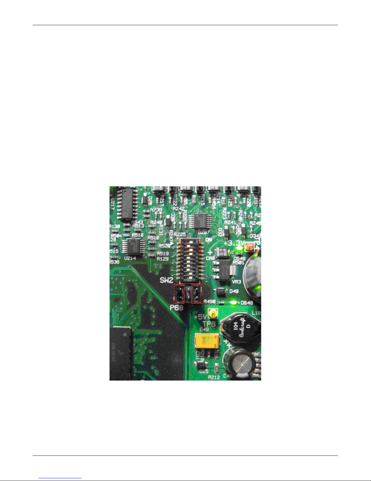
3. Control board DIP switch SW2 Switch 1 must be ON, Switch 2 must be OFF.
Figure 18 DIP switch locations on Liebert iCOM control board
Operation
4. P68 must have a jumper placed between the top and bottom two pins on the left side and one
placed between the top and bottom pins on the right side, the two middle pins should be left
unconnected.
5. Next go to Service/Diagnostics Service Menu and find S379. Set this option to Feedback and note
that S380 will go to Yes and S381 will go to Ongoing. If Feedback is already selected then go to
line S380 and manually select Yes. This means that the Liebert iCOM is doing auto calibration on
the valve using the feedback now available through the potentiometer. Wait for S381 to say Idle
and then the process is complete.
22
Page 29
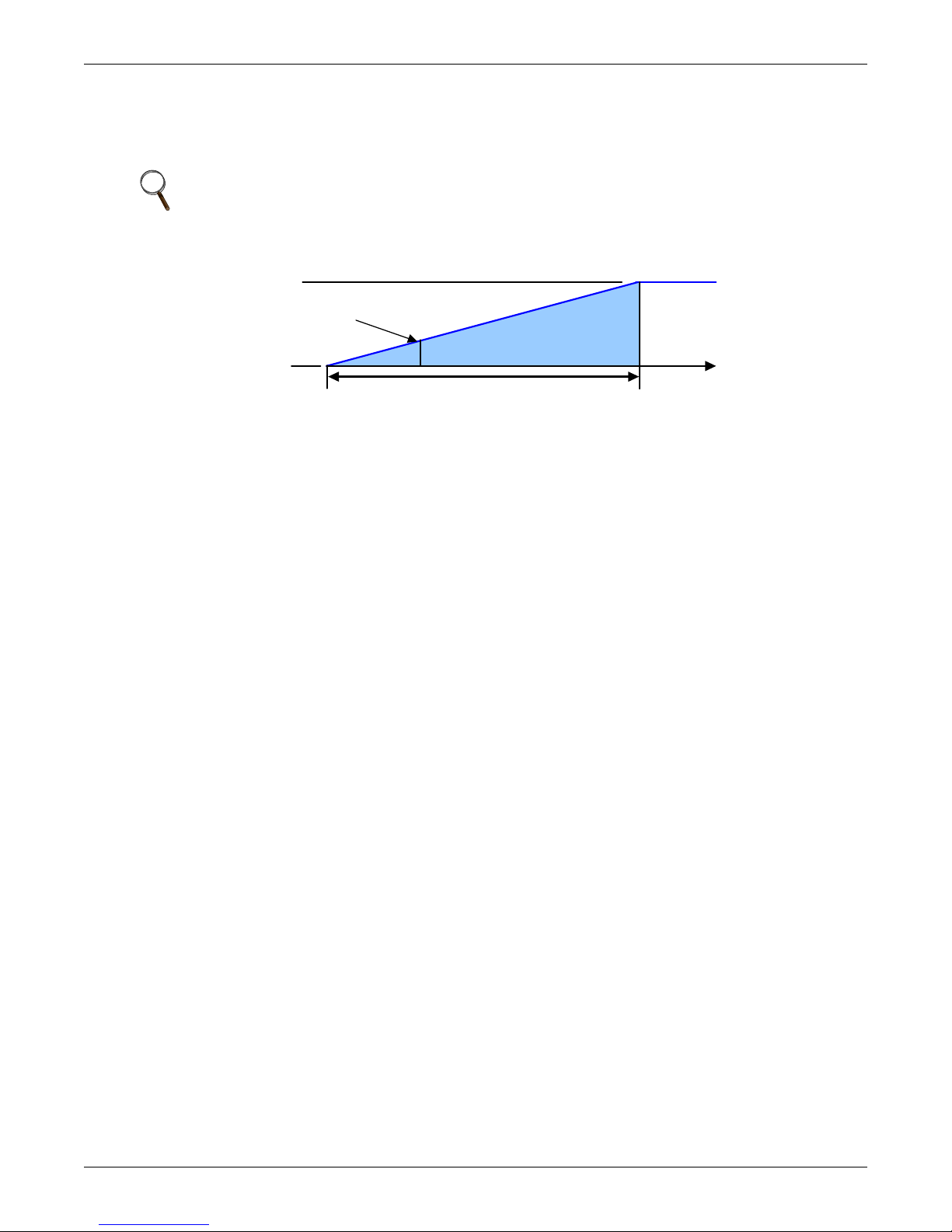
Chilled water units that contain a motorized ball valve(s) are connected to the control by an analog
+ 100%
Cooling
Cooling
½ Proportional Band
0% - C losed
Requested Position
100% Fully Open
0%
Setpoint
+ Temp
output. The analog output is driven proportionally to the call for cooling as shown in Figure 19.
Larger chill water units may contain two motorized ball valves in which both valves are controlled in
parallel.
NOTE
Depending on the valve specifications, the voltage output may be a 0-10VDC or a 2-10VDC that
is scaled automatically within the control.
Figure 19 Chilled water valve control (example: cooling)
3.3 Temperature Control—Second Cooling Source
Certain cooling units are available with a second source of cooling within the unit. These typically are
compressorized models with an additional chilled water or free-cooling coil.
Operation
3.3.1 Differential Temperatures / Controls (Comparator Circuit)
Delta T (Temperature Difference) Between Room and Glycol
The comparator circuit determines if the glycol / chilled water temperature of the second cooling
source is low enough to provide at least partial cooling capacity. The comparator circuit has three settings (DT Between Room / FC Type, [Service Menu, Setpoints]):
•No
•Contact
•Value
The No setting is for standard compressorized and chilled water units that do not have a second cooling source. The No setting can also be used to disable the second source of cooling.
The Contact setting is used when an external input is being used to determine when the second cooling source is to be activated. The external control communicates to the Liebert unit via contact closure.
• Closed = cooling enabled
• Open = cooling disabled.
The Value setting is the factory default setting (8°F [4.4°C]) on free-cooling and dual cooling units. If
the temperature difference between the second source cooling fluid parameter, Free-cooling Fluid
Temperature (User Menu, Sensor Data) and room air is equal to or greater than the adjustable DT
Between Room Air / FC Fluid (Service Menu, Setpoints) value, then the second source cooling fluid
will be used to provide at least partial cooling.
Sensors used for this delta T are: room/local sensor or the return air sensor; and the glycol sensor.
If this delta T is true, the following actions will be performed:
1. The Free-Cooling Status indication will show “On” instead of “Off”.
2. The compressor band will be shifted to the right by 100%, and within the first 100% the freecooling valve band will take place (see Figure 20).
The cooling portion of the proportional band is doubled, with the first half of the band controlling
the free-cooling valve and the second half controlling the compressors.
23
Page 30
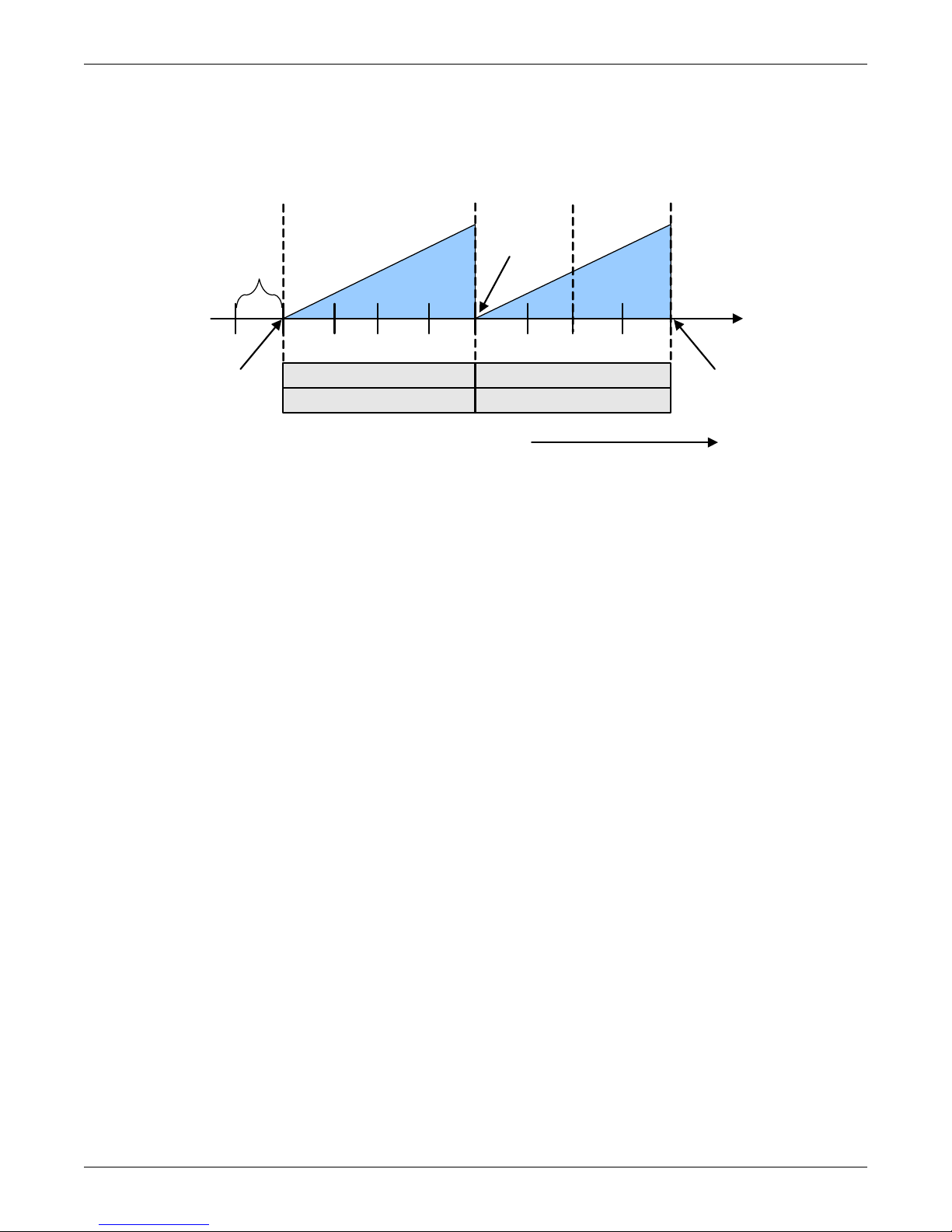
Figure 20 Second cooling source and two-step compressorized cooling
7571 72 73 7470
Increasing Tem perature
Cool 2
On
Cool 1
On
+ 100%
Cooling
Valve 100%
Open
Valve
Closed
½ Dead -
band
76 77 78 79
+ 200%
Cooling
0%
Cooling
2nd
Source
Comp
½ Proportional Band ½ Proportional Band
Band1: 2
nd
Source B and 2: Compressors
Temp Setpoint: 70°F
Proportional Band: 8°F
Deadband: 2°F
Minimum Chilled Water Temperature—This feature permits the user to select the minimum
chilled water temperature that allows simultaneous operation of the second cooling source (chilled
water control) and compressor control. This feature is enabled in the Service menu under Setpoints,
parameter Minimum CW Temp.
Operation
If the water temperature is below this minimum chilled water setpoint, parameter Minimum CW
Temp Value, (Service Menu, Setpoints), the control will operate ONLY the second cooling source control, i.e., the compressor is locked out. Above the minimum chilled water setpoint, assuming the fluid
temperature is below the return room air temperature (delta T between room and glycol = true), the
control will operate the second cooling source control and compressor control simultaneously if
needed.
If the Minimum CW Temp is disabled, the second cooling source temperature is ignored, the control
will always operate the second cooling source and compressors simultaneously when the load requires
it.
GLYCOOL™ Cooling—Free-Cooling
When GLYCOOL cooling is available, the temperature control will calculate a total cooling requirement of 200% rather than 100%. Assuming that full GLYCOOL capacity is available, the GLYCOOL
valve opens proportionally as the requirement for cooling rises from 0 to 100%. If more than 100%
cooling is required, then the compressors are activated at 150% and 200% respectively (133%, 163%,
180% and 200% for a four-step system). If full GLYCOOL capacity is not available, then the GLYCOOL valve will be opened proportionally over a cooling requirement band equal to the available
GLYCOOL capacity. The compressors would be activated when the GLYCOOL capacity is exceeded.
For example, if the GLYCOOL capacity is 60%, then the GLYCOOL valve would be full open at 60%
cooling requirement and the compressors would activate at 110% and 160% cooling requirement. In
order to reduce compressor cycling and prevent hunting, GLYCOOL capacity first becomes available
when the entering glycol temperature is at least 8°F (4.4°C) (22% capacity) below the return air temperature, or 3°F (1.7°C) below the return air temperature for two hours. GLYCOOL capacity is 100%
when the glycol temperature is 25°F (13.9°C) below the return air temperature. The system will continue to operate in Econ-O-Cool mode as necessary as long as the entering glycol temperature
remains at least 3°F (1.7°C) (0% capacity) below the return air temperature. If GLYCOOL is not
available, the temperature control will operate the compressors in the same manner as a two-step or
four-step system without GLYCOOL.
Dual Cooling Source
If dual cooling is available, the system operates in the same manner as a GLYCOOL system, except
that it is assumed that 100% chilled water capacity is available any time the chilled water temperature is 3°F (1.7°C) below the return air temperature.
24
Page 31
3.4 Temperature Control—Reheat
0%
Heating
65 70
Heat 3
On
½ Dead -
band
66 67 68 69
Heat 2
On
Heat 1
On
Heat 3
Off
Heat 2
Off
Heat 1
Off
-100 %
Heating
½ Proportional Band
Decreasing Temperature
Temp Setpoint: 70°F
Proportional Band: 8°F
Deadband : 2°F
If the room air temperature becomes too cold, the control will call for heating. Heating mode is controlled by the Temperature Proportional Band, explained in 3.2.1 - Temperature Proportional
Band.
3.4.1 Three-Stage Electric, Hot Gas and Hot Water Reheat
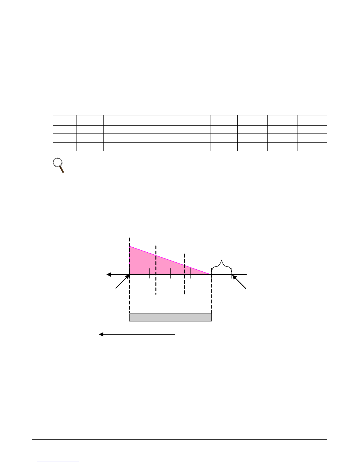
The Reheat Proportional Band is divided into three equal parts, each representing one reheat stage.
As the Temperature Proportional Band increases the call for heating from 0% to -100%, stages 1
through 3 are switched On, as shown in Figure 21. Your unit will have one of the nine reheat configuration types shown in Table 4.
Table 4 Reheat configuration types
Type A B C D E F G H I
Stage 1 Electric 1 Electric 1 Electric 1 Hot Gas Hot Gas Hot Gas Hot Water Hot Water Hot Water
Stage 2 - Electric 2 Electric 2 - Electric 1 Electric 1 - Electric 1 Electric 1
Stage 3 - - Electric 3 - - Electric 2 - - Electric 2
NOTE
1. Hot gas / hot water are not influenced by the setting of electric reheat during
dehumidification.
2. Hot gas output will be set only if the selected compressor is in operation.
Operation
Figure 21 Three-stage heating
3.4.2 SCR Reheat
SCR reheat is a type of electric reheat that provides tighter temperature control than staged electric
reheat. SCR reheat capacity modulation is achieved by pulsing the reheat On and Off. Full capacity is
achieved by constantly energizing the reheat. Units equipped with SCR reheat can operate in Tight or
Standard mode. By default, cooling units with SCR reheat are factory-set to operate in Tight mode.
The mode of operation can be set by adjusting the SCR Control Type parameter (Service Menu, Setpoints).
Tight Mode
In Tight mode, the compressors and reheats are operated at the same time to provide maximum tem-
perature control. The temperature deadband is set to zero at the factory. In a cooling unit with SCR
reheat and two single-step compressors, the first single-step compressor is started and full reheat
25
Page 32
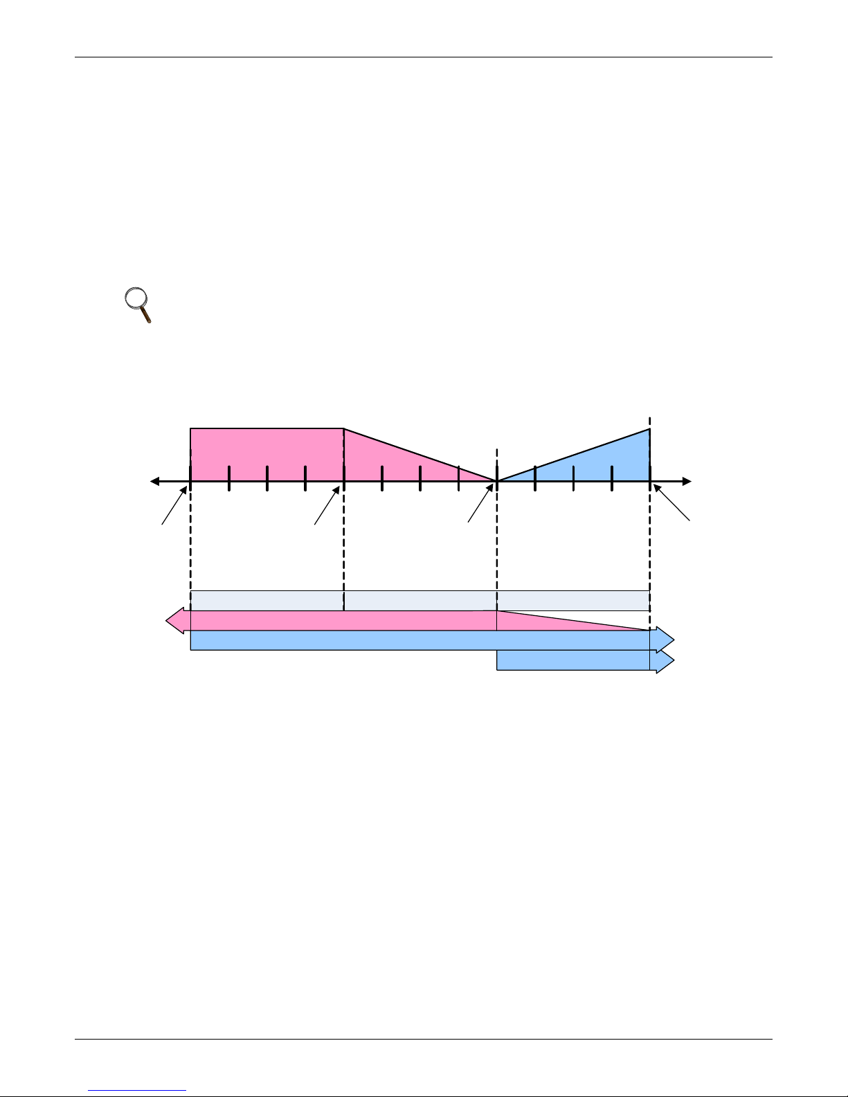
capacity is provided at 0% calculated output from the Temperature Proportional Band. As the call for
Temp Setpoint: 70°F
Proportional Band: 8°F
Deadband: 0°F
Cool 1
Off
-100 %
Heating
Cool 2
On
SCR On
Cool 1 On
Cool 2
Off
SCR
Off
-200%
Heati ng
100%
Cooling
0%
½ Proportional Band ½ Proportional Band ½ Proportional Band
7465 7066 67 68 69 71 72 73646362
Cooling 2 On
Cooling 1 On
SCR Reheat On
cooling increases from 0% to 100%, the reheat capacity is slowly reduced by pulsing the reheat. At
100% call for cooling, the reheat is deactivated and the second single-step compressor is started. As
the call for cooling is reduced, the reheat capacity is slowly increased. When the call for cooling
returns to 0%, the second single-step compressor is deactivated.
If the Temperature Proportional Band calculates a call for heating from 0% to -200%, the first single-step compressor remains activated and full reheat capacity is provided. Based on the factory
default settings, the first single-step compressor is deactivated when the control reaches -200% call
for heating. The compressor remains deactivated until the control calls for 0% heating. The compressor activation and deactivation points can be adjusted in the Service menu under Setpoints.
Figure 22 illustrates how a cooling unit with two single-step compressors and SCR reheat operates
when the SCR Control Type is set to Tight mode.
NOTE
Some cooling units are not suited for a strict NO LOAD application. These cooling units
require a minimal load in the space. Consult factory for verification.
Figure 22 Two single-step compressors with SCR reheat set to Tight mode
Operation
Standard Mode
In Standard mode, the SCR reheat operates only when the Temperature Proportional Band calls for
heating. SCR reheat output is adjusted proportionally as the Temperature Proportional Band varies
the requirement for heating from 0% to -100%. Compressors operate only when there is a call for cooling as described in 3.2.2 - Compressor Control.
Figure 23 illustrates how SCR reheat operates when SCR Control Type is set to Standard mode.
26
Page 33
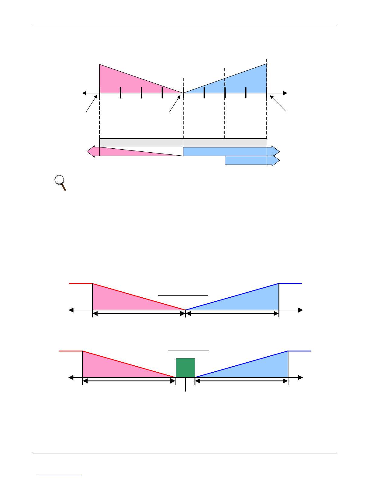
Figure 23 Two single-step compressors with SCR reheat set to Standard mode
Temp Setpoint: 70°F
Proportional Band : 8°F
Deadband : 0°F
Cool 2
On
Cool 1
On
Cool 2
Off
Cool 1 Off
SCR Off
SCR
On
0%
100 %
Cooling
-100%
Heati ng
7471 72 7366 67 68 69 70
½ Proportional Band
Cooling 1 On
Cooling 2 On
½ Proportional Band
SCR On
0%
Setpoint
0%
+ 100%
Dehumidification
Dead-
band
Humidification
-Hum + Hum
0%
Setpoint
½ Proportional Band
Dehumidification
- 100%
Humidification
-100%
humidification
Without Deadband
With Deadband
Humidification
-Hum
+ 100%
Dehumidification
+ Hum
Dehumidific ation
½ Proportional Band
½ Proportional Band ½ Proportional Band
NOTE
Using SCR in Standard mode in conjunction with variable cooling capacity (e.g., chilled water
valve or digital compressor) provides ultimate capacity control and energy-efficiency gains.
Operation
3.5 Humidity Control
The control uses the humidity proportional band to determine which operation to perform (dehumidification/humidification) and how much capacity to provide. The Humidity Proportional Band is a user
defined range that is divided into two equal parts for dehumidifying and humidifying. The Humidity
Setpoint is located between these two equal parts.
An optional Humidity Deadband range can be defined, which is equally divided on either side of the setpoint and separates the two halves of the proportional band. Figure 24 illustrates how the humidity proportional band is evenly divided on either side of the humidity setpoint, with and without a deadband.
Figure 24 Humidity proportional band
When the return air humidity deviates from the setpoint, either dehumidification or humidification is
activated. If the return air humidity increases, the control calls for 0% (none) to 100% (full) dehumidifying capacity, based on how far the humidity penetrates the dehumidification portion of the proportional band. If the return air humidity decreases, the control calls for 0% (none) to -100% (full)
humidifying capacity based on how far the humidity penetrates the humidification portion of the proportional band.
27
Page 34

When the return air humidity reaches the end of the proportional band, either 100% or -100%, full
dehumidification or full humidification capacity is provided. No operation is performed when a 0%
call is calculated. The control varies the call for dehumidifying and humidifying in 1% increments as
the return air humidity moves through the proportional band halves.
The deadband range is used to widen the setpoint. When the return air humidity falls within the
deadband, the control operates the same as if the humidity equaled the setpoint exactly. This setting
helps maximize component life by preventing excessive component cycling. The Humidity Proportional Band and Humidity Deadband parameters are in the Service menu under the Setpoints submenu. The Humidity Setpoint parameter is in both the User menu and Service menu under
Setpoints.
3.5.1 Humidification
Infrared Humidifier
There are two types of infrared humidifiers: small pan (IFS) and large pan (IFL). The operating mode
of each is similar, however, some of the variables or timings differ. The Challenger has different fill
times because of the size ofthe pan.S
Infrared humidifiers are started at 100% humidification request, and stopped at 0%. Infrared humidifiers cannot be driven in proportional mode.
Table 5 Parameters for infrared humidifier control
Parameter
Humidity in Last xx Hours 15 hours 15 hours 15 hours
Fill Time 33 seconds 56 seconds 27 seconds
Humidifier On Time 440 seconds 576 seconds 568 seconds
Flush Rate 150% 150% 150%
IFS Default IFL Default
Operation
Liebert
Challenger
An autoflush system automatically controls a water makeup valve to maintain proper levels in the
infrared humidifier water pan during humidifier operation. If humidification is needed and 15 hours
have elapsed since the last time the humidifier was on, then the humidifier is not turned on until the
valve completes an initial fill of the humidifier pan. This pre-fill is about 30 seconds for a small pan
and 60 seconds for a large pan. The valve continues to fill and flush the pan for about 4-1/2 minutes
for a small pan or 7-1/2 minutes for a large pan. Pan size is selected based on unit specifications and
is preset at the factory.
During humidifier operation, with the flush rate set at the default of 150%, the valve is opened periodically to add water to the pan (about 45 seconds every 7 minutes of humidifier operation for a small
pan, or 80 seconds every 10 minutes of operation for a large pan). This adds enough water to the pan
to cause about a third of the total water used to be flushed out of the overflow standpipe located in the
humidifier pan. This action helps to remove solids from the pan. The flush rate is adjustable from
110% to 500% in 10% intervals. Default is 150%. If the water quality is poor, it may be desirable to
increase the water flushing action above the normal 150% rate. Also, if the supply water pressure is
low, the flush rate adjustment can be increased so that sufficient water level is maintained during
humidification. The flush rate parameter, Infrared Flush Rate (Service Menu, Options Setup), is
adjustable from 110%-500%.
External Humidifier Control—Optional
A factory-supplied option may be provided to allow a start-stop command to be sent to the control of a
remote-mounted humidifier.
Steam Generating Canister Humidifier
The Steam Generating Humidifier has its own separate control board that manages the canister and
steam rate. Liebert iCOM sends an On-Off command to relay a call for humidification.
28
Page 35
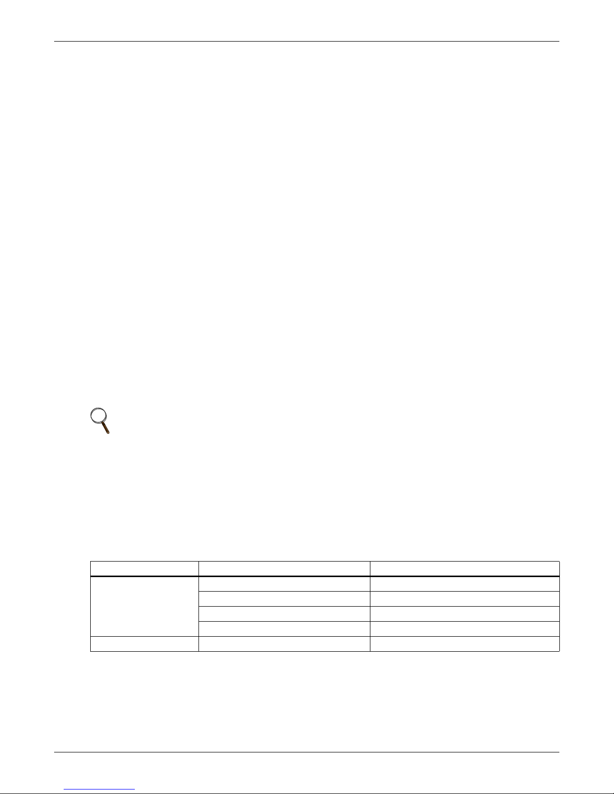
3.5.2 Dehumidification
The Dehumidification Enable parameter (Service Menu, Options Setup) allows for enabling/disabling
the dehumidification function.
A call for dehumidification is calculated in the same way as a cooling request. The components
(valves, compressors) will follow this dehumidification request as soon as it is higher than the request
for cooling.
Dehumidification Low Limit
Low Limit 1 and Low Limit 2 are used to avoid overcooling a room during dehumidification. When a
low limit is reached, a compressor or the liquid cooling source that is used for dehumidification is disabled. It is re-enabled when the return air temperature rises. The Low Limit 1 and 2 settings are in
the Service menu under Setpoints.
Low Limit 1: Low Limit 1 will disable one of two compressors for dehumidification. If only one compressor is set for dehumidification, or if the dehumidification source is chilled water, this limit will
not be visible and will be inactive.
Low Limit 2: Low Limit 2 will disable both compressors for dehumidification. This limit will also
stop dehumidification in single compressor units and in chilled water units.
The limits become active when the return air temperature drops below a temperature value equal to
the sum of the temperature setpoint plus the value set on Low Limit 1 and 2 (the Low Limit settings
are negative values).
Operation
A dehumidification source is deactivated if the return air temperature drops below the Deactivation
Temperature, as in this example:
Temperature Setpoint: 70°F (21.1°C)
Low Limit Value: -7°F (-3.8°C)
Deactivation Temperature: 62°F (16.6°C)
NOTE
If a cooling unit is equipped with SCR reheat and the SCR Control Type parameter is set to
Tight mode, then Low Limit 2 will be ignored, see 3.4 - Temperature Control—Reheat.
Dehumidification Compressor Quantity
Under Factory Settings in the Advanced menu there is an item called Dehumidification With Comp.
This item will be set to either 1, 2, 1 or 2, or BOTH. This setting determines which compressors are
used for dehumidification. It also determines if Low Limit 1 will be available and impacts how the
reheats will operate during dehumidification. The Dehumidification With Comp field is set when the
cooling unit is built and should not be adjusted without consulting the factory first. Table 6 outlines
which Low Limit settings will be available, based on the Dehumidification With Comp selection.
Table 6 Dehumidification With Comp settings
Available to Set Value Dehumidification With Comp Setting Default Setting On
[blank] (units without compressors) All Chilled Water Units
Low Limit 2 only
Low Limit 1 & 2 Both (both compressors dehumidify) —
1 (Compressor 1 dehumidifies only) Liebert DS
2 (Compressor 2 dehumidifies only) —
1 or 2 (Compressor 1 and 2 alternate) —
Low Limit 1 & 2 will be available only on cooling units with two compressors when Dehumidification
With Comp is set to BOTH (see WARNING on page 30).
29
Page 36

Operation
Reheat During Dehumidification
Hot gas reheat or hot water reheat will start as described in 3.4 - Temperature Control—Reheat,
when the temperature decreases during the dehumidification process.
The parameter Electric Reheat Operation defines how the heaters react in case the temperature
decreases during the dehumidification process. This parameter does not impact SCR reheat operation. The Electric Reheat Operation parameter is in the Advanced menu under Factory Settings and
should not be adjusted without factory approval.
No—No electric reheat allowed during dehumidification process.
Delayed—This setting applies only to two-compressor units with BOTH compressors selected for
dehumidification. The electric reheats are prevented from turning on until Low Limit 1 is reached. At
this condition, one stage of dehumidification is disabled and the reheats are activated. At Low
Limit 2, both stages of dehumidification are disabled. When Delayed is selected on units with a single
compressor selected for dehumidification (Dehumidification With Comp Setting: 1, 2, and 1 or 2), the
reheats will operate in the same manner as they do for Staged as described below. Delayed is the
default setting for Liebert DS units.
Staged—This setting applies to one or two compressor units. Electric heaters will stage as described
in 3.4.1 - Three-Stage Electric, Hot Gas and Hot Water Reheat. Staged is the default setting for
Challenger 3000 units. On two compressor units with staged reheat selected and Dehumidification
With Comp set to BOTH, the control allows for operating two compressors and reheats simultaneously. It is very important that electrical service to the unit be sized and wired for this option if
selected.
WARNING
!
If the electrical service to the unit is not properly sized, it could trip the building circuit
breakers (or fuses) or, in extreme cases, damage the building wiring. This Warning applies
only when the Dehumidification With Comp is set to BOTH and the Electric Reheat
Operation is set to Staged. Consult factory before making any changes to the default settings.
3.6 Control Types
3.6.1 Temperature and Humidity Control Types
The Liebert iCOM control has three Temperature and Humidity Control Types: Proportional, PI and
Intelligent. Each control type affects the timing and intensity of the cooling/heating and humidifying/dehumidifying operations. The Control Type parameter is in the Service menu under Setpoints.
Proportional—If Proportional Control is selected, the percent cooling/heating requirement is determined by the difference between the air temperature sensor reading and the temperature setpoint. As
the air temperature rises above the temperature setpoint, the percent cooling required increases proportionally (from 0 to 100%) over half the programmable temperature proportional band (See 3.2.1 -
Temperature Proportional Band). The percent heating requirement (0 to -100%) is determined
the same way when the air temperature falls below the setpoint. The humidifying/dehumidifying
operations are controlled in the same manner as the cooling/heating operations; however, the humidity sensors, setpoints and proportional bands are utilized. The Proportional control type is commonly
selected on compressorized units.
PI—If PI Control is selected, the percent cooling/heating requirement is calculated by adding
together two individual terms, proportional and integral. The proportional term is calculated in a
manner similar to the previously described Proportional control. The integral term (sometimes called
“reset action”) is calculated by measuring how much and for how long the air temperature/humidity
has been above or below the setpoint. If the actual air temperature/humidity is above the setpoint, the
percent requirement is slowly but continuously increased until the total is sufficient to bring the
return room air back to the setpoint. This control type is commonly selected on freecooling and dualcool units.
Intelligent—If Intelligent Control is selected, the air temperature/humidity is controlled at or near
the setpoint. The percent temperature/humidity adjustment required is calculated based on logic that
30
Page 37

is programmed into the control. These rules simulate the actions that a human operator would take if
manually controlling the system. This control type is commonly selected on chilled water units.
NOTE
The actual air temperature sensor reading is always displayed on the Status menu. The value
displayed for the return air humidity sensor reading depends on the Humidity Sensor Control
Type (see 3.6.2 - Humidity Sensor Reading Control Types).
3.6.2 Humidity Sensor Reading Control Types
The Liebert iCOM control has three humidity sensor control types: Relative, Compensated and Predictive. The humidity sensor control adjusts how the Temperature and Humidity Control determines
the percent requirement for humidification/dehumidification. The humidity sensor control type
parameter, Humidity Control Type, is in both the User and Service menus under Setpoints.
Relative—The actual return air humidity sensor reading is sent to the Temperature and Humidity
Control to determine if and how much humidification/dehumidification is required. The actual return
air humidity reading is displayed on the Status menu. Unnecessary dehumidification can result when
overcooling occurs during a dehumidification cycle. This is because a higher than normal relative
humidity (RH) reading is caused by overcooling the room. This extends the dehumidification cycle.
Later, when the dehumidification ends and the return air temperature rises to the setpoint, the RH
reading falls. The final RH reading will then be lower than actually desired. If significant overcooling
occurred, the RH could be low enough to activate the humidifier.
Compensated—The actual return air humidity sensor reading is sent to the Temperature and
Humidity Control where the Humidity Setpoint is adjusted based on how much the return room air
temperature deviates from the desired temperature setpoint. The adjusted humidity setpoint is used
for humidification percent requirement determination. For every 1°C deviation from the temperature
setpoint the humidity setpoint is changed by 3% RH, inversely proportional: if the temperature
increases, the humidity setpoint is decreased, and vice versa. The recalculated humidity setpoint is
shown as the Actual Humidity Setpoint (User Menu, Sensor Data). As the humidity setpoint is automatically adjusted, the high and low humidity setpoints (User Menu, Set Alarms) are adjusted
accordingly. The unadjusted humidity sensor reading is displayed on the Status menu.
Predictive—The actual return air humidity sensor reading is adjusted before it is sent to the Temperature and Humidity Control. The humidity sensor reading is adjusted based on how much the
return room air temperature deviates from the desired temperature setpoint. For every 1°C deviation
from the temperature setpoint, the humidity sensor reading is changed by 3% RH, directly proportional: if the temperature increases, the humidity reading is increased and vice versa. The adjusted
humidity sensor reading is displayed on the Status menu. Units are shipped from the factory with
Predictive humidity control set as default.
If Compensated or Predictive humidity sensor control is selected, overdehumidification is avoided.
When overcooling occurs, causing an increase in the relative humidity sensor reading, the humidity
control program predicts what the RH will be when the dehumidification cycle ends and return air
temperature returns to the setpoint. This allows the dehumidification cycle to end at the proper time.
The Compensated and Predictive humidity sensor control can reduce energy consumption by minimizing compressor and reheat operation, and eliminating unnecessary humidifier operation.
Operation
NOTE
The historical humidity sensor graphs will display the real (unadjusted) sensor readings, no
matter which Humidity Control Sensor Type is selected. The graphical sensor data is in the
User menu under Graphics.
31
Page 38
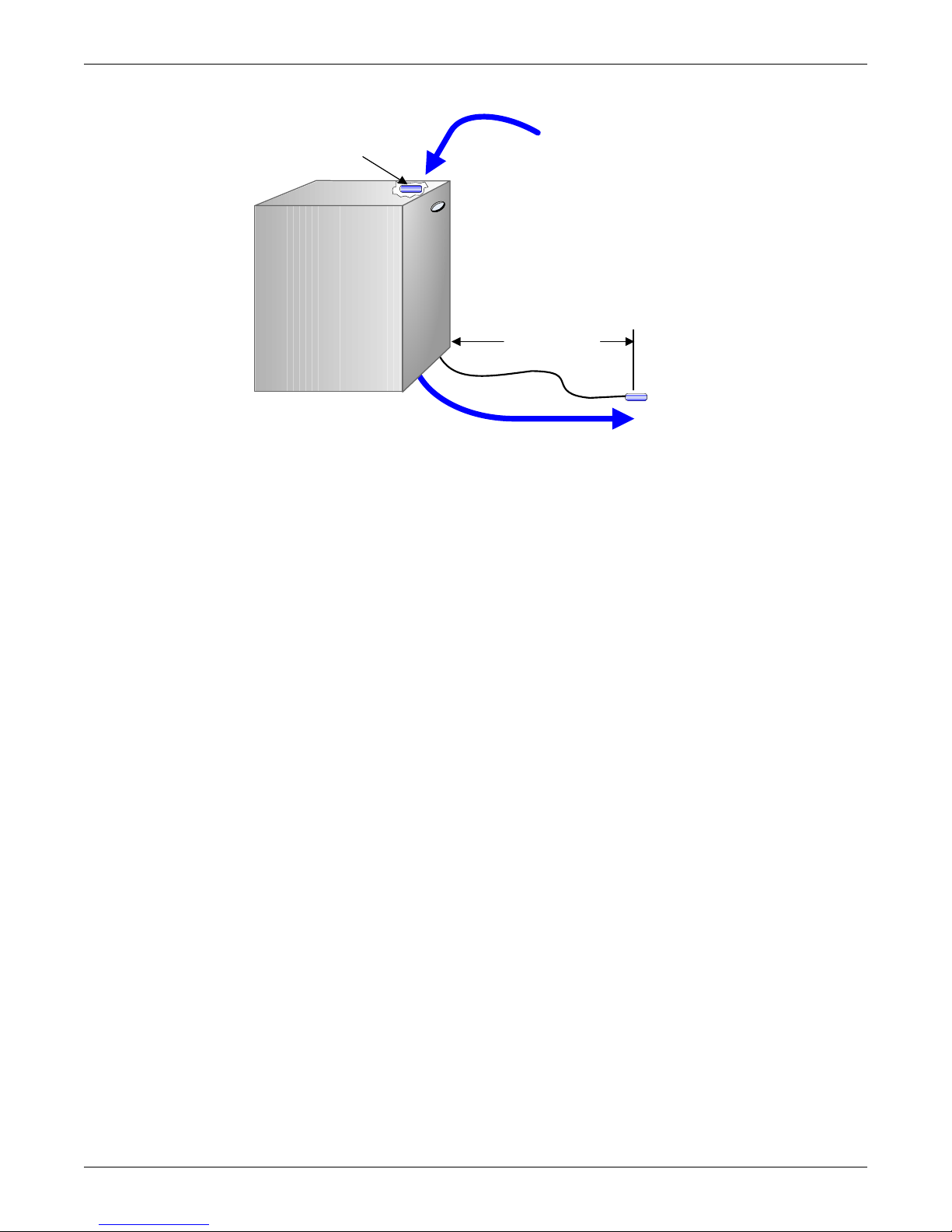
Figure 25 Placing temperature and temperature/humidity sensors
Temperature
Sensor
5 to 15feet
(1.5 to 4.5m)
Internal Temperature
and Humidity Sensor
Return
Air
Supply Air
Liebert Precision Cooling Unit
Operation
32
Page 39

3.7 Supply Control
3.7.1 Supply Air
The Supply Air sensor can be used to control, limit or reference the discharge air temperature of the
cooling unit. The desired supply sensor operation can be selected in the Service, Setpoints menu. The
optional supply air temperature sensor allows use of either the Supply Air control or the Supply Limit
control. This sensor can be added to existing Liebert iCOM controls by purchasing the supply sensor
and wiring harness. The supply air sensor must be connected to P13 pins 1 & 2. Contact your local
Emerson representative for pricing and installation.
• Supply Control: When the supply sensor is set to Control, the unit will control the amount of
cooling / heating being provided based on maintaining the discharge air temperature. The return
air sensor will still control the humidity of the room.
NOTE
If unit is equipped with a 3P actuator type valve then the valve must be changed to utilize the
feedback signal. See 3.2.3 - Chilled Water Control.
• Supply Limit: Chilled water units may be set up with the supply air sensor to maintain a minimum air temperature under a raised floor to help prevent condensation. In order to avoid supply
temperatures that are too low, the Supply Limit can influence the opening of three-point or analog actuators or the output of analog values. The control compares the deviation from the return
air setpoint and the supply limit setpoint, and calculates the output to the actuator from the
smaller deviation.
• Cooling Only: When Cooling Only is selected, the cooling capacity of the system (valve or compressor) is modulated based on the supply temperature, but allows the fan speed to be controlled
by a different sensor.
• Disable: Setting the supply sensor to Disable will allow the supply sensor to be monitored but
will not affect the control output of the unit.
Operation
NOTE
Supply control and limit are calculated on each unit, independent of the other sensor readings
on the network.
When the supply air sensor is set up for Supply control, additional Supply Air configuration
parameters (valve pulse, cooling filters and return compensation) can be used to further enhance
the supply air control.
• The valve pulse and cooling filter timer can be adjusted to prevent oscillating around the supply
setpoint and still allow for rapid valve adjustments to compensate for heat load changes. Contact
your local Liebert service personnel for adjustments.
• Return Compensation begins to increase the supply air setpoint when the return air decreases
below the return air setpoint.
Example
Setting the return compensation value in the Service, Setpoints menu to 5°F (2.7°C) will
increase the supply setpoint from 50°F to 55°F (10°C to12.8°C) when the return temperature is
at the low limit of the proportional band.
33
Page 40

3.8 Event Types and Properties
Liebert iCOM events are used to inform the user of cooling unit operational status. All events are
recorded in the Event Log, which is in the User Menu. The user can change the type (alarm, warn,
message) and time delay of some events and can also enable or disable some events. These event settings are in the Service Menu under Set Alarms, pages 3 to 7. If an event has a safety function (high
pressure, low pressure, main fan overload, etc.) the safety function will be executed in any case, independent of the selected event type or if enabled or disabled. The timing will function as set.
NOTE
Not all critical event properties can be adjusted.
Event Types
• Message: If this event occurs, it will only be entered into the event log.
• Warning: If this event occurs, a warning will be generated and entered into the event log. The
general alarm relay will be activated only if parameter Warning Activates Alarm Relay located in
the Service menu under Alarm Setup is set to Yes (Yes is the default setting from the factory)
• Alarm: If this event occurs, an alarm will be generated and entered into the event log. An alarm
does not necessarily switch off the whole cooling unit; it depends on which alarm occurs. If a
standby unit is set, any alarm will stop the faulty unit and ask the standby unit to start. Standby
activation is achieved on alarms ONLY; messages or warnings will not start the standby unit. For
more on standby units, see 4.0 - Teamwork.
Time Delay
Delays the event reaction once it is triggered. The time delay applies to safety functions and is
entered in seconds.
Enable or Disable
Disabled events do not show up in the event log, on the display or on monitoring devices. Also, the
common alarm relay will not be activated if a disabled alarm occurs. Safety functions, such as lockout
compressor in case of high pressure are still performed.
Operation
NOTE
Once a disabled event (set to Warn or to Alarm) becomes active, it will lock itself. Disabled
events may be reset only through the menu item Reset Disabled Alarms.
NOTE
The value of the external delay includes the internal delay if it is greater than the internal
delay.
The minimum setting of the external delay is the value of the internal delay. This is valid only
for values marked with *.
34
Page 41

Operation
Table 7 Possible event settings—some events not available in all units
Event
(Before Action Occurs)
MAIN FAN OVERLOAD 2 seconds 5 seconds / 0 – 9999 * ALM
LOSS OF AIRFLOW 3 seconds 3 seconds / 0 – 9999 * ALM
CLOGGED FILTERS 2 seconds 2 seconds / 0 – 9999 * WRN
HIGH ROOM TEMP 1 Min After Fan On 30 seconds / 0 – 9999 Fixed to WRN
LOW ROOM TEMP 1 Min After Fan On 30 seconds / 0 – 9999 Fixed to WRN
HIGH ROOM HUM 1 Min After Fan On 30 seconds / 0 – 9999 Fixed to WRN
LOW ROOM HUM 1 Min After Fan On 30 seconds / 0 – 9999 Fixed to WRN
HIGH TEMP SENSOR A 1 Min After Fan On 30 seconds / 0 – 9999 Fixed to WRN
LOW TEMP SENSOR A 1 Min After Fan On 30 seconds / 0 – 9999 Fixed to WRN
HIGH HUM SENSOR A 1 Min After Fan On 30 seconds / 0 – 9999 Fixed to WRN
LOW HUM SENSOR A 1 Min After Fan On 30 seconds / 0 – 9999 Fixed to WRN
COMP 1 OVERLOAD Internal Calc. no ALM
COMP 2 OVERLOAD Internal Calc. no ALM
COMP 1 HIGH PRESSURE Internal Calc. no ALM
COMP 2 HIGH PRESSURE Internal Calc. no ALM
COMP 1 LOW PRESSURE Internal Calc. no ALM
COMP 2 LOW PRESSURE Internal Calc. no ALM
COMP 1 PUMPDOWN FAIL Internal Calc. no ALM
COMP 2 PUMPDOWN FAIL Internal Calc. no ALM
DIG SCROLL1 HIGH TEMP Internal Calc. no ALM
DIG SCROLL2 HIGH TEMP Internal Calc. no ALM
EL HEAT HIGH TEMP 5 Sec 0 sec / 0 – 9999 WRN
WORKING HRS EXCEEDED 0 Sec 0 sec / 0 – 9999 Fixed to WRN
SMOKE DETECTED 2 Sec 2 sec / 0 – 9999 * ALM
WATER UNDER FLOOR 2 Sec 2 sec / 0 – 9999 * ALM
COND PUMP-HIGH WATER 2 Sec 2 sec / 0 – 9999 * ALM
Internal Delay
LOSS OF FLOW
5 Sec
Reset Delay: 10 Sec
STBY GLYCOL PUMP ON 2 Sec 2 sec / 0 – 9999 * ALM
STANDBY UNIT ON 2 Sec 2 sec / 0 – 9999 * ALM
HUMIDIFIER PROBLEM 2 Sec 2 sec / 0 – 9999 * ALM
NO CONNECTION w/Unit1 Internal Calc. - WRN
UNIT X DISCONNECTED Internal Calc. - WRN
LOSS OF POWER 0 Sec No ALM
CUSTOMER INPUT 1 2 Sec 2 sec / 0 – 9999 * ALM
CUSTOMER INPUT 2 2 Sec 2 sec / 0 – 9999 * ALM
CUSTOMER INPUT 3 2 Sec 2 sec / 0 – 9999 * ALM
CUSTOMER INPUT 4 2 Sec 2 sec / 0 – 9999 * ALM
CALL SERVICE 2 Sec 2 sec / 0 – 9999 * MSG
HIGH TEMPERATURE 2 Sec 2 sec / 0 – 9999 * MSG
LOSS OF AIR BLOWER 1 2 Sec 2 sec / 0 – 9999 * ALM
REHEAT LOCKOUT 2 Sec 2 sec / 0 – 9999 * WRN
HUMIDIFIER LOCKOUT 2 Sec 2 sec / 0 – 9999 * WRN
FC LOCKOUT 2 Sec 2 sec / 0 – 9999 * WRN
COMPRESSOR(S) LOCKOUT 2 Sec 2 sec / 0 – 9999 * WRN
COMP 1 SHORT CYCLE 0 Sec 0 - 9999 MSG
COMP 2 SHORT CYCLE 0 Sec 0 - 9999 MSG
Default Delay / Selectable
(Before Action Occurs)
2 sec / 0 – 9999 * ALM
Type
(default)
35
Page 42
3.8.1 High- and Low-Temperature and Humidity Events
High- and low-temperature and humidity alarms can be set for both the internal and optional external sensors. If a sensor reading exceeds a preset threshold, a warning will appear. These warnings are
ignored after unit startup for a minimum of 1 minute. To increase the delay to warn, see 3.8 - Event
Types and Properties. The threshold settings are located in both the User and Service menus
under Set Alarms.
To apply threshold limits on the internal cooling unit sensors, the Return Sensor Alarms must be
enabled. The high and low temperature and humidity internal sensor thresholds can then be set. To
apply threshold limits on the optional external sensors, the Sensor A alarms must be enabled. The
high and low temperature and humidity external sensor thresholds can then be set. If no external
sensors are connected to the unit, it is recommended that the Sensor A Alarms be disabled.
NOTE
The event messages will automatically reset if the temperature/humidity stays 1.8°F
(1°C)/ 2% RH below or above the threshold for one minute.
3.8.2 User Inputs
The user can connect and specify up to four inputs depending on unit configuration. The user inputs
are digital inputs that can provide information about an event associated with the unit or space. The
customer input configuration settings are in the Service menu under Set Alarms, Screen 2 of 7. The
choices for the customer inputs are shown in Table 8 along with their associated reaction. A terminal
strip is provided in the cooling unit to connect your contact closure to. You have the ability to set the
control to react on an open or closed contact.
Operation
NOTE
To enabled/disabled, delay activation and set event type (alarm, warn, message) see Event
Types on page 34.
Table 8 Customer inputs
Setting Reaction
Smoke Event Only
Water Alarm Event Only
C PMP Alarm Event Only
Flow Alarm Event Only
Stdby G Pmp Event Only
Stdby Unit Event Only
C-Input 1 Event Only
C-Input 2 Event Only
C-Input 3 Event Only
C-Input 4 Event Only
Rht Lockout Event + Electrical Heaters Disabled
Hum Lockout Event + Humidifier Disabled
Rht+Hum Lock Event + Electrical Heaters and Humidifier Disabled
Comp Lockout Event + Compressor(s) Disabled w/o Pump Down
Call Service Event Only
High Temp Event Only
Air Loss Event Only
FC Lockout Event + Free Cooling Disabled
Heater Alarm Event + Heaters Off (PeX Only)
Flow AL SD Event + Shut Down the Unit
Flow AL LC Event + Lockout Compressors, No Pump Down (enabled only if at
Comp Lock PD Event + Compressor(s) Disabled w/ Pump Down
Enable FC Forces Free Cooling to On
HTRJ VFD Activates the HEAT REJ VFD ALARM; no other function
HTRJ TVSS Activates the HEAT REJ TVSS ALARM; no other function
least one compressor is on; auto-reset depends on input status)
36
Page 43

3.8.3 Liebert iCOM-DO
The Liebert iCOM-DO is an optional discrete output relay card that can be connected to the Liebert
iCOM controls that will provide a dry alarm contact for monitoring systems. The Liebert iCOM-DO is
a direct replacement of the Liebert ENV-DO card that was supported on previous Liebert control systems. The Liebert iCOM-DO allows simultaneous use of the Liebert Intellislot cards as the Liebert
iCOM-DO communicates over the CAN sensor bus network instead of the iGMNet interface.
A single Liebert iCOM-DO card can be connected to Liebert iCOM, which converts up to 15 configurable alarms to a discrete output (relay). The Liebert iCOM-DO setup can be found in the Service, Liebert iCOM-DO menu. The Liebert iCOM-DO is pre-configured and will automatically be identified by
the Liebert iCOM controller. The default alarm configuration matches the original Liebert ENV-DO
card alarm mapping.
Table 9 Alarm mapping
#String Notes
01 Cooling Status The output is set as soon as the unit is providing any cooling.
02 Heating Status The output is set as soon as the unit is providing any heating.
03 Humidifying Status The output is set as soon as the unit is providing any humidification.
04 Dehumidifying Status The output is set as soon as the unit is providing any dehumidification.
05 High Temperature The output is set as long as the high temperature alarm is active.
06 High Humidity The output is set as long as the high humidity alarm is active.
07 Low Temperature The output is set as long as the low temperature alarm is active.
08 Low Humidity The output is set as long as the low humidity alarm is active.
09a High Head Pressure C1 The output is set as long as the compressor 1 high head pressure alarm is active.
09b High Head Pressure C2 The output is set as long as the compressor 2 high head pressure alarm is active.
10 Loss of Airflow The output is set as long as a loss of air flow alarm is active
11 Change Filters The output is set as long as a change filter alarm is active
12 Water Alarm The output is set as long as a water alarm is active
13 Condensing Pump Alarm The output is set as long as the condensing pump alarm is active
14 Glycool Status The output is set when there is free cooling available
15 Unit On The output is set as soon as the unit is turned on
An event is active as long as it is not acknowledged. Once acknowledged, an alarm remains active until the event
situation is not true anymore and the event is reset by the board, which switches off the red LED and the general
alarm relay.
Operation
37
Page 44

3.8.4 Possible Event Notifications
Table 10 lists examples of alarms and warnings that can be configured for a cooling unit. When any
of these occur, they will appear on the Liebert iCOM Status menu and will be recorded in the Liebert
iCOM Event log.
Table 10 Event notifications—large or small display
Event Type
COMP 1 HRS EXCEEDED WRN
COMP 2 HRS EXCEEDED WRN
EL HEAT1 HRS EXCEEDED WRN
EL HEAT2 HRS EXCEEDED WRN
EL HEAT3 HRS EXCEEDED WRN
FC HRS EXCEEDED WRN
GENERAL ALARM ALM
GLYCOL TEMP SENSOR WRN
HIGH CW TEMP WRN
HUM HRS EXCEEDED WRN
HUMIDIFIER PROBLEM —
HW/HG HRS EXCEEDED WRN
LOSS OF CW FLOW ALM
NETWORK FAILURE WRN
ON-OFF KEY DISABLED WRN
POWER ON MSG
POWER OFF MSG
ROOM SENSOR FAILURE ALM
UNIT DISABLED MSG
UNIT HRS EXCEEDED WRN
UNIT ON MSG
UNIT OFF MSG
UNIT DISABLED MSG
UNIT SHUTDOWN MSG
UNIT SYNCHRONIZATION MSG
SENSOR A FAILURE WRN
SLEEP MODE MSG
STANDBY MODE MSG
SUPPLY SENSOR FAILURE WRN
Operation
3.9 Wellness—Next Maintenance Calculation
The next maintenance calculation, as well as the included diagnostics feature, will help keep the cooling unit running at peak performance to ensure minimum component stress and maximum reliability. The diagnostics will help the service engineer evaluate the unit’s operation since the last
maintenance.
38
Page 45

3.9.1 Calculation of Next Maintenance and Diagnostics
If the unit includes any of the following components, they are included in the calculation:
•Fan(s)
• Compressor 1
• Compressor 2
• Electric Heaters
• Humidifier
For each component, the next maintenance will be calculated from the following parameters:
• Standard service interval (1, 2 or 4 times a year) (to be set)
• Working hours (counted)
• Number of starts (counted)
• Average running time (calculated)
• Optimum number of starts per hour (to be set)
• Maximum number of starts per hour (to be set)
• Maximum bonus to enlarge time to next maintenance (to be set)
• Maximum penalty to reduce time to next maintenance (to be set)
Calculating Unit Wellness
Liebert iCOM keeps tabs on the condition of a cooling unit, determining its wellness and projecting
when service will be needed, for the entire unit as well as for individual components. This assists in
scheduling maintenance calls and helps pinpoint components likely to require service.
Operation
Liebert iCOM displays a graphic for needed maintenance. It begins with the standard maintenance
interval—12 months, six months or three months—and adjusts that based on its calculation of components’ wellness.
To calculate wellness, Liebert iCOM keeps a running total of component working hours and the number of times it has been started. Liebert iCOM relates that data to the optimum/maximum starts per
hour. Accordingly, Liebert iCOM will increase or decrease the time before the next service call will be
needed.
The more frequently a component starts, the sooner it is likely to need maintenance. If, for example, a
unit’s fan runs continuously, but it’s compressor starts and stops often, Liebert iCOM records that
and calls for maintenance based on the compressor’s wellness factor.
Alarms and warnings, such as clogged filters or high or low pressure, reduce the time till the next
maintenance to zero. If the alarm is cleared and reset, Liebert iCOM recalculates wellness. It begins
with the pre-alarm maintenance time and factors in the alarm.
Parameters for Next Maintenance Calculation
General Maintenance Settings
• Maintenance Frequency—can be set as one to 12 months or to zero, which disables maintenance calculation
• Max. Bonus—increases the time to next maintenance with the set value, if all components run
optimally (number of starts, average running time)
• Max. Penalty value—decreases the time to next maintenance with the set value, if some components run in non-optimum way (number of starts, average running time)
• Last Maintenance—date can be set from service-engineer; informational
• Service-Engineer—name of the service engineer; editable
• Reset—puts all counters of all components, such as (motor, compressors, heaters and humidifier),
at zero and starts a new maintenance calculation (reset to be done after maintenance)
39
Page 46

Operation
Fans / Heaters / Humidifier Settings and Diagnostics
• Number of starts and Working hours are counted separately since the last maintenance. Total
working hours can be read in the standard working hours window (customer window).
• Average Working Hours is the calculation, resulting from starts and working hours.
• Starts per Day Optimum is the number of starts considered as optimum.
• Starts per Day Worst is the number of starts considered as hunting (worst case).
• Number of Alarms counts the alarms, happened between two service intervals.
• Actual Bonus is calculated from number of starts and average working time. Can be positive
(bonus) or negative (penalty). This value influences the time remaining to the next maintenance.
Compressor 1 / 2 Settings and Diagnostics
• Number of starts and Working hours are individually counted since the last maintenance. Total
working hours can be read in the standard working hours window (customer window).
• Average Working Hours is the calculation, resulting from starts and working hours.
• Starts per Day Optimum is the number of starts considered as optimum.
• Starts per Day Worst is the number of starts considered as hunting (worst case).
• Number of HP Alarms counts the high-pressure alarms, happened between 2 service intervals.
• Number of LP Alarms counts the low-pressure alarms, happened between 2 service intervals.
• Number of TH Alarms counts the thermal protection alarms, happened between 2 service intervals.
• Actual Bonus is calculated from number of starts and average working time. Can be positive
(bonus) or negative (penalty). This value influences the time remaining to the next maintenance.
40
Page 47

4.0 TEAMWORK
Unit-2-Unit (U2U) communications via a private network will allow the following functions to be
placed into operation when the requirement exists. The user must install the correct hardware
(see 5.0 - Installing a Liebert iCOM Unit-to-Unit Network) and properly program the units for
the selected functionality.
The Liebert iCOM network can perform the following functions:
The Teamwork Mode functions allow for multiple stages of cooling/heating and humidification/dehumidification. Teamwork Mode can be used to prevent environmental units from “fighting,”
where one environmental unit might be cooling while another unit is heating.
The Standby (Lead/Lag) function allows one or more units to be set as “Running” and “Standby” for
activation in case of an alarm. This function also allows the units to be programmed in a rotation to
help ensure “Standby” unit operation.
The Cascade Operation function allows additional units to be staged-on based on the temperature
or humidity requirement.
4.1 Teamwork Modes
Groups of cooling units connected to a network can be set up to work together in any of three teamwork modes:
•No Teamwork
• Teamwork Mode 1
• Teamwork Mode 2
Teamwork
All Liebert iCOM-controlled cooling units on a network must be set to run in the same teamwork
mode.
4.1.1 Application of Teamwork Modes
• No Teamwork: Multiple zones in one room
• Teamwork Mode 1: Balanced load (small groups of units inside the same environment)
• Teamwork Mode 2: Unbalanced load (large rooms, not all units will have the same load) (work
well for most applications)
All units in a network will run in the same Teamwork Mode.
4.1.2 No Teamwork
All cooling units work independently, responding to their own sensors.
Standby function and unit rotation are possible, but cascading is not (see Standby and Cascade on
page 43). Autoset will not adjust the proportional band in this mode.
4.1.3 Teamwork Mode 1
Teamwork Mode 1 works best in small rooms with balanced heat loads. The return temperature and
humidity sensor readings of all units in operation (fan on) are averaged by the master unit, Unit #1,
and used for control. The master unit will send the operating requirements to all operating units
according to unit numbers, rotated by one unit every 24 hours.
In this teamwork mode, most of the parameters are shared; if set in any one of the units, all other
units will follow with the same settings. AutoSet will adjust the proportional band in Teamwork
Mode 1, see 3.2.1 - Temperature Proportional Band.
The master unit evenly divides the system proportional band among the number of available units.
Each unit will receive instruction on how to operate from the master unit based on how far the system
deviates from the setpoints.
41
Page 48
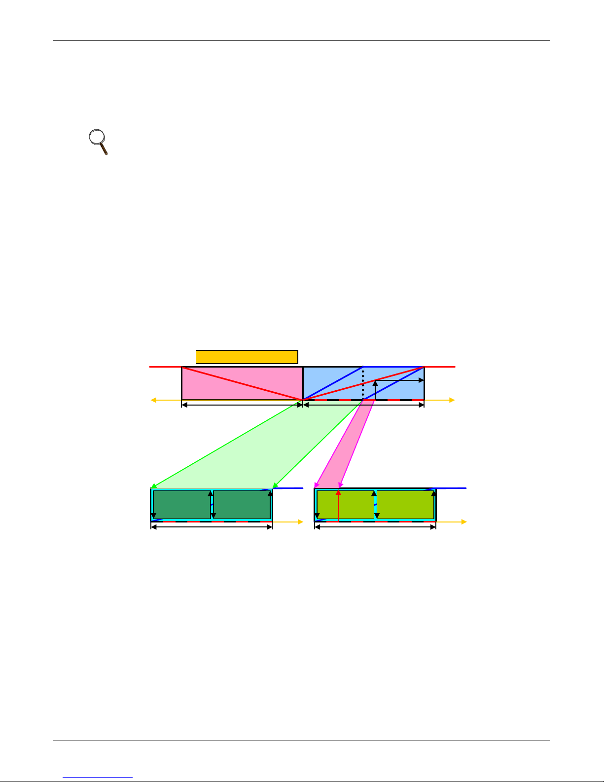
Teamwork
C1 C2
cooling
+100 %
0%
1 /2 Pr oporti onal Band
+tem p.
Un it 2 D eviat ion : 20 %
Setp oint
C1 C2
cooling
+100%
0%
1/2 Pr opor tional Band
+temp.
Setp oint
0%
Setpoin t
- tem p.
-100 %
+tem p.
1 /2 Propor ti onal Band +100%
1 /2 Pr oporti onal Band
heati ng
100 %
60 %
0%
System D eviatio n : 60%
Sys tem propor ti onal band
Un it 1 D eviat ion : 100 %
The number of available units is calculated like:
• In non-standby configuration: all units with fan on
• In typical standby function (no cascade): all units with fan on
• In cascade mode: all units that could operate (no alarm, which forces the unit to switch off, unit
not switched off, etc.)
NOTE
1. Proportional actuators (chilled water valve, free-cooling actuator) are driven in parallel in
all units.
2. Changeover to second cooling source, low limit during dehumidification and low supply
limit control air local functions, managed from each unit independently.
Figure 26 shows how two cooling units work together in Teamwork Mode 1. Since Unit 1 and Unit 2
are available to operate, the master unit, Unit 1, averages the temperature and humidity sensor readings from each unit.
The master unit determines that a 60% call for cooling is required for the system. Since there are two
available cooling units, each unit makes up half of the system proportional band; Unit 1 handles 050% system call for cooling and Unit 2 handles 51-100%. For every 1% system call for cooling, each
unit provides 2% of its total cooling capacity.
The 60% system call for cooling exceeds the 50% Unit 1 can provide, so Unit 1 operates at full capacity. The remaining 10% system call for cooling (60% - 50% = 10%) is handled by Unit 2. Unit 2
responds by operating at 20% cooling capacity (50% ÷ 10% = 20%).
Figure 26 Teamwork Mode 1 with two cooling units
42
Page 49

4.1.4 Teamwork Mode 2
Teamwork Mode 2 is designed to prevent units within a group from working against each other or
“fighting.” It is best applied in large rooms with unbalanced heat loads. In Teamwork Mode 2, all
parameters are shared equal to Mode 1, and Unit #1 averages all of the available unit sensor readings
on the network to define whether there is a cooling, heating, dehumidification or humidification
request.
If there is a cooling request, all units are released to start cooling resources according to their own
temperature readings; heating is disabled for all units and vice versa. Same for humidity control.
If the network average would ask for 0% proportional band, the most demanding request (highest or
lowest temperature of all units, highest or lowest humidity of all units) would be used to define the
operation to be performed.
Teamwork Mode 2 does not rotate; unevenly distributed working hours to be expected. Autoset will
not adjust the proportional band in this mode.
NOTE
In Teamwork Mode 2, all units must have the same setpoints. The units’ proportional band,
deadband and related settings may differ.
4.1.5 Standby—Rotation
Typical Standby (Lead/Lag) Function
Teamwork
This function can be performed in any teamwork mode, including NO Teamwork.
One or more units can be defined to be Standby; the normal status of standby units is Standby Off
(fan off).
In case one regular unit has an alarm that is defined (to be defined in the alarm configuration), to
switch on a standby unit, the faulty unit will switch off and the standby unit will switch on.
If the next unit has an alarm, the next standby unit will be started. If no more standby units are
available, the unit with a non-critical alarm that permits unit operation will be switched on again
(water detection, fan alarm, fire alarm etc. will not permit unit restarting).
The standby function can be rotated daily (setting the time), weekly (setting the day of the week and
time) or monthly (setting the first weekday of the month and time).
The rotation is performed with a selectable number of units: if 1 is selected, to standby rotates from
1-2 to 2-3 in a 4 units configuration with two standby units, and rotates from 1-2 to 3-4 in the same
configuration, when the rotation parameter is set to 2.
NOTE
Before entering standby mode, units will operate the fan only for 3 minutes to cool the electrical
heaters, remove steam from the unit, etc.
Standby and Cascade
Cascade is possible in Teamwork Mode 1 only.
Standby units will start if an alarm occurs in one of the operational units. If the standby units are
cascaded, they will also start and work with the regular operational units if the temperature or
humidity cannot be controlled by the operational units; before a high or low temperature / humidity
condition occurs. Cascaded units are switched off again as soon as the temperature / humidity returns
back to normal.
The master unit defines its proportional band according to the number of available units (see 4.1.3 -
Teamwork Mode 1).
When a standby unit receives a request for full heating or cooling from the master unit (see 3.2.1 -
Temperature Proportional Band), it will respond to the request after its control delay.
NOTE
Cascaded units are not included in the calculation of the average temperature / humidity.
43
Page 50
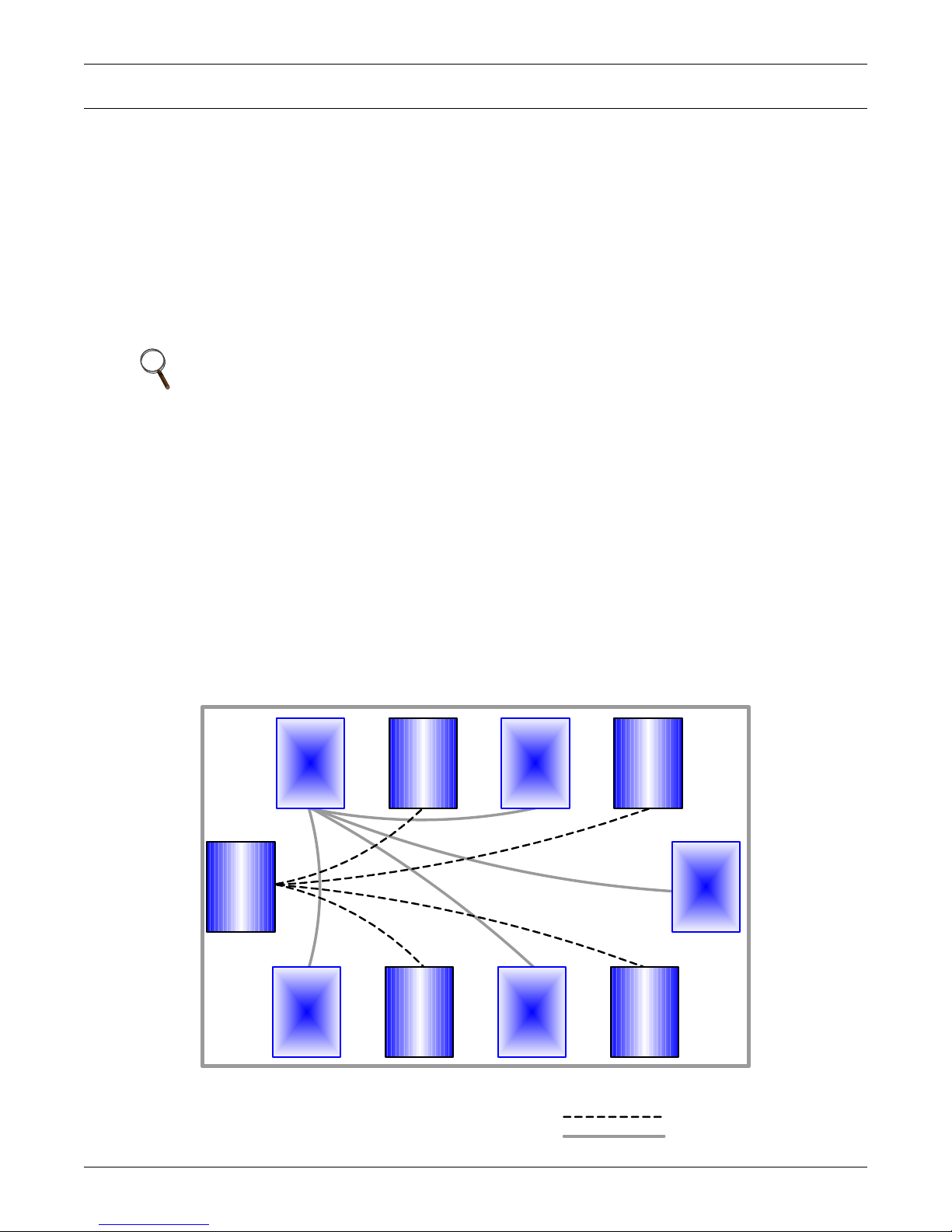
Installing a Liebert iCOM Unit-to-Unit Network
Precision Cooling units 1 through 5 are on Teamwork Rotation #1
Precision Cooling units 6 through 10 are on Teamwork Rotation #2
Communication Cables , Teamwork Rotation #1
Communication Cables , Teamwork Rotation #2
81
2 7 36
5 9 410
5.0 INSTALLING A LIEBERT ICOM UNIT-TO-UNIT NETWORK
Connecting multiple Liebert iCOM-controlled cooling units in an Ethernet Unit-to-Unit (U2U) network enables the units to work together to achieve efficient cooling and humidity control of the conditioned space. Networking enables setting up the cooling units to exchange data for various modes of
operation:
• Teamwork
• Lead/Lag-Standby
• Rotation
• Cascade
However the cooling units are set up, a large display may be used to control and view the operational
status of individual units or of the entire system.
NOTE
The maximum number of cooling units that may be interconnected is 32.
5.1 Placement of Cooling Units
Refer to the cooling unit product manuals for details on installation. Also consider these factors when
planning for installation of cooling units with Liebert iCOM controls:
• heat load in the conditioned space
• cooling air distribution
• number of operating units versus number of standby cooling units
• location of the network switch—An Ethernet cable cannot exceed 328 feet (100m)
5.1.1 Balancing Operating and Standby Units
Assign identification to the units in a manner that balances the operating units and standby units
according to room layout and heat-load requirements. For example, identify the operating units with
numbers 1 through 5 and the standby units 6 through 10. Refer to Figure 27.
Figure 27 Standby unit layout example—10 Precision Cooling units in room
44
Page 51

5.2 U2U Hardware: Cables and Network Switch
Plan wiring runs for U2U communication when designing the layout of your conditioned space. In
addition to general good wiring practices, take into account:
• Ethernet CAT5 or greater cable is required for interconnecting the units.
• Maximum distance must not exceed 328 feet (100m).
• A device to boost the Ethernet signal may be used to exceed the 328 feet (100m) length limitation.
• Ethernet network should be private—set up only for management and control of the cooling units.
• Keep control and communication cables away from power cables to prevent electromagnetic interference.
• Do not bend cables to less than four times the diameter of the cable.
• Do not deform cables when securing in bundles or when hanging them.
• Keep cables away from devices that can introduce noise into them, such as machines, fluorescent
lights, and electronics.
• Avoid stretching Ethernet cables—tension when pulling cables should not exceed 25 pounds
(11kg).
• Do not secure Ethernet cables with any method that might damage them; use approved hangers,
such as telephone wire/RG-6 coaxial wire hangers, available at most hardware stores.
Minimum Network Switch Requirements
• IEEE 802.3; IEEE 802.3u
• 10/100 Mbps speed
• Multiple 10/100 RJ-45 ports—one shared; RJ-45 Uplink port
The Liebert vNSA
networks. See Liebert vNSA on page 50 for details.
™
is an approved powered network switch designed to support Liebert iCOM U2U
Installing a Liebert iCOM Unit-to-Unit Network
45
Page 52
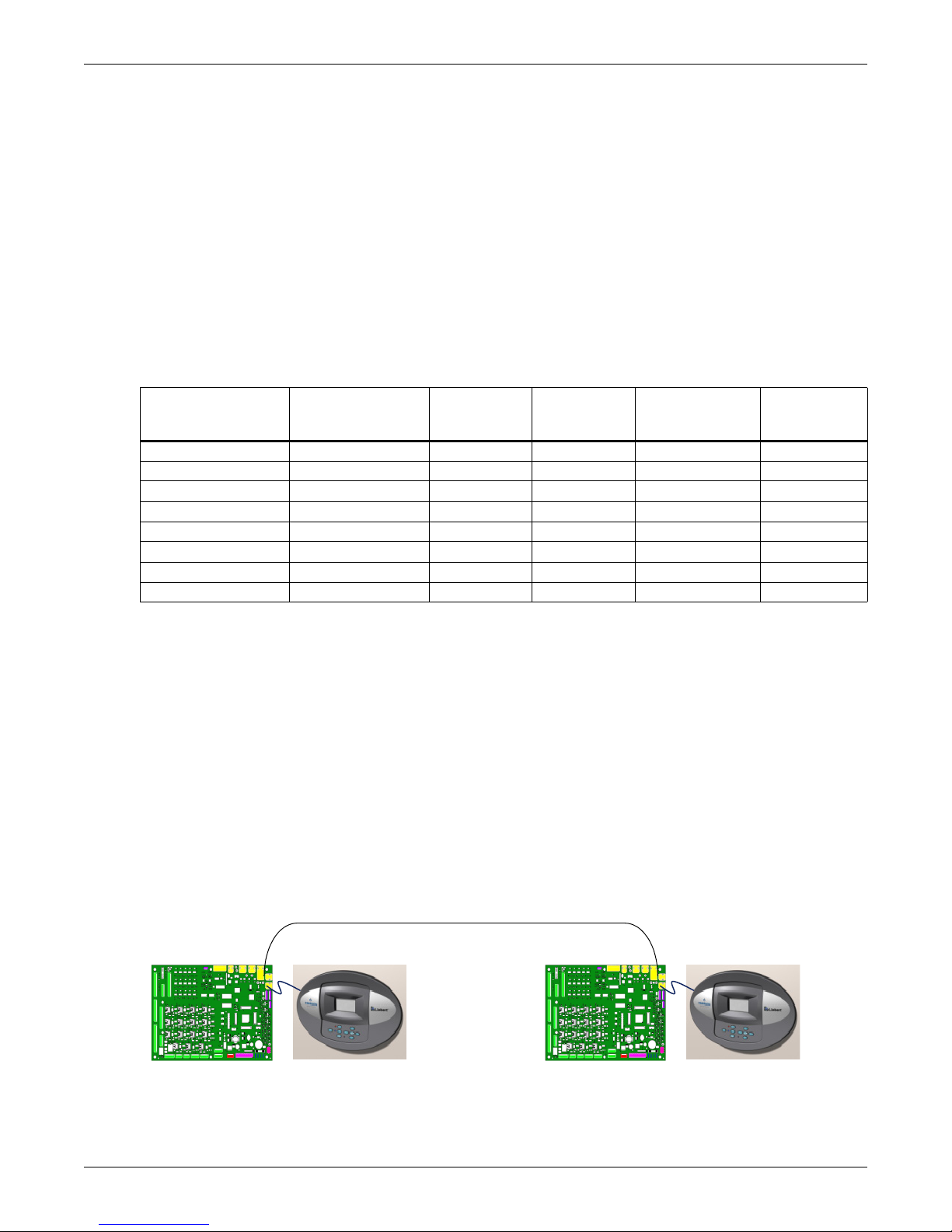
5.3 Wiring for Unit-to-Unit Communications—U2U
Cooling units come from the factory-wired for stand-alone operation.
Liebert iCOM U2U Ethernet Network
The Liebert iCOM U2U network must be isolated from other network traffic. The network switch(es)
that connect Liebert iCOM controls need to be dedicated to supporting only Liebert iCOM communication. The U2U network cannot be connected to the building or IT network. If network communication is ever lost (failed network switch, etc.), all Liebert iCOM-controlled cooling units will continue to
operate as independent units.
The Liebert iCOM control can support up to 64 nodes on one network. An input/output board, large
display, and large wall-mount display are each considered one node. Of the 64 nodes that may be connected, no more than 32 may be input/output boards (32 cooling units). A small display is not considered a node. Small displays connect directly to input/output boards that do not have large displays
attached to them. The following table illustrates how a network can be configured.
Table 11 Sample Liebert iCOM network configurations
Sample
Configuration
12020No
22021Yes
33030Yes
42110Yes
58441Yes
6323200Yes
7322755Yes
8 32 0 32 32 Yes
Input/Output
Boards
Large
Displays
Installing a Liebert iCOM Unit-to-Unit Network
Private
Switch
Required
Small
Displays
Wall Mount
Large
Displays
Network communication can be configured during system startup by a Liebert-trained technician. For
technical issues contact:
Liebert Technical Service
1050 Dearborn Drive
Columbus, Ohio 43235
Telephone: 1-800-LIEBSRV (1-800-543-2778)
E-Mail: [email protected]
5.3.1 Wiring a Liebert iCOM U2U Network
Small Displays
Two cooling units, each with a small display: To network two cooling units, each with a small
display, connect a crossover CAT5 cable between the P64 connectors on each cooling unit’s Liebert
iCOM input/output board. A network switch is not needed (see Figure 28).
Figure 28 Connecting two cooling units, each with a small display using a crossover Ethernet cable
Three or more units with small displays: To network three or more cooling units, each equipped
with a small display, connect a straight-through CAT5 Ethernet cable from the P64 connector on each
cooling unit’s Liebert iCOM input/output board to a common network switch (see Figure 30).
46
Page 53
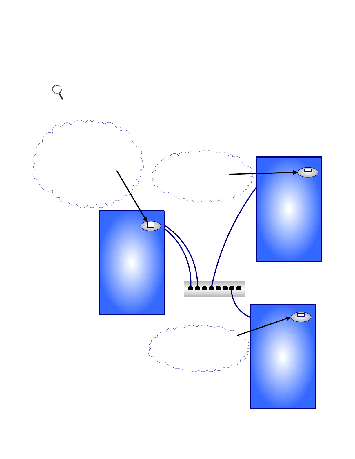
Large Displays
Network
Switch
Liebert Cooling Unit
with Small Liebert
iCOM Display
Liebert Cooling Unit
with Small Liebert
iCOM Display
Liebert Cooling Unit
with Large Liebert
iCOM Display
Display Service/Network
Liebert iCom Display Menu
IP Address: 192.168.001.001
U2U A d dres s:1
Group #: 1
---------------------------------------
Display Service/Network
Liebert Cooling Unit
Control Board Menu
IP Address: 192.168.001.002
U2U Address: 2
Group #: 1
Display Service/Network
Liebert Cooling Unit
Control Board Menu
IP Address: 192.168.001.003
U2U Address: 3
Group #: 1
Display Service/Network
Liebert Cooling Unit
Control Board Menu
IP Address: 192.168.001.004
U2U Address: 4
Group #: 1
A network switch is required to enable Ethernet communication on one or more cooling units with
large displays. Each cooling unit with a large display requires two straight-through Ethernet cables
from a network switch. One cable connects to port P64 on the Liebert iCOM input/output board and
the other straight-through cable connects to the female-female coupler provided with the unit. Connect the red crossover cable, which is provided with the cooling unit, between the coupler and the P64
port on the back of the large display (see Figure 32).
NOTE
Only cooling units with large displays are supplied with a female-female coupler inside the
unit from the factory.
Figure 29 U2U network setup diagram
Installing a Liebert iCOM Unit-to-Unit Network
47
Page 54
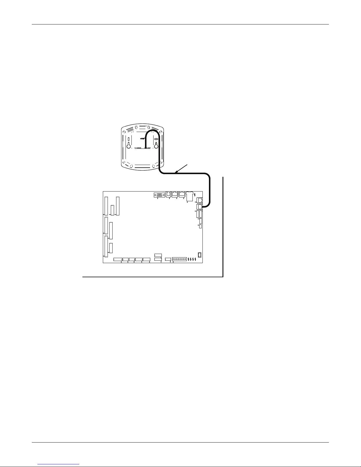
Wall-Mount Large Display
182964
Page 1
Rev. 0
Small Graphics Display
On Unit Accent
Stand-Alone Unit
6-Wire Cable
P66 P67
CAN CAN
iCOM
Microprocessor and I/O Board
E1
E3
P4
P22
P38
P39
P53
P52
P54
P51
TB1
E2
E4
P43
Unit Electronics Compartment
P40
P8
P32
P34
P33
P35
P36
E5
P18 P65
P61
P63
P64
P66
P7
P13
P12
P11
P67
Only large displays can be used for remotely monitoring and controlling cooling units connected on
the same network. Each wall-mount large display requires 120V input power; Liebert provides an AC
adapter wall plug. A straight-through Ethernet cable must be connected between the network switch
and the P64 port on the back of the display. This will enable control and monitoring capabilities to
any cooling unit connected to the network.
Combining Large and Small Displays on a U2U Network
Setting up a network of cooling units equipped with large and small displays requires a network
switch. The controls are to be connected to the switch as described above.
Figure 30 Wiring a small display for stand-alone operation
Installing a Liebert iCOM Unit-to-Unit Network
48
Page 55
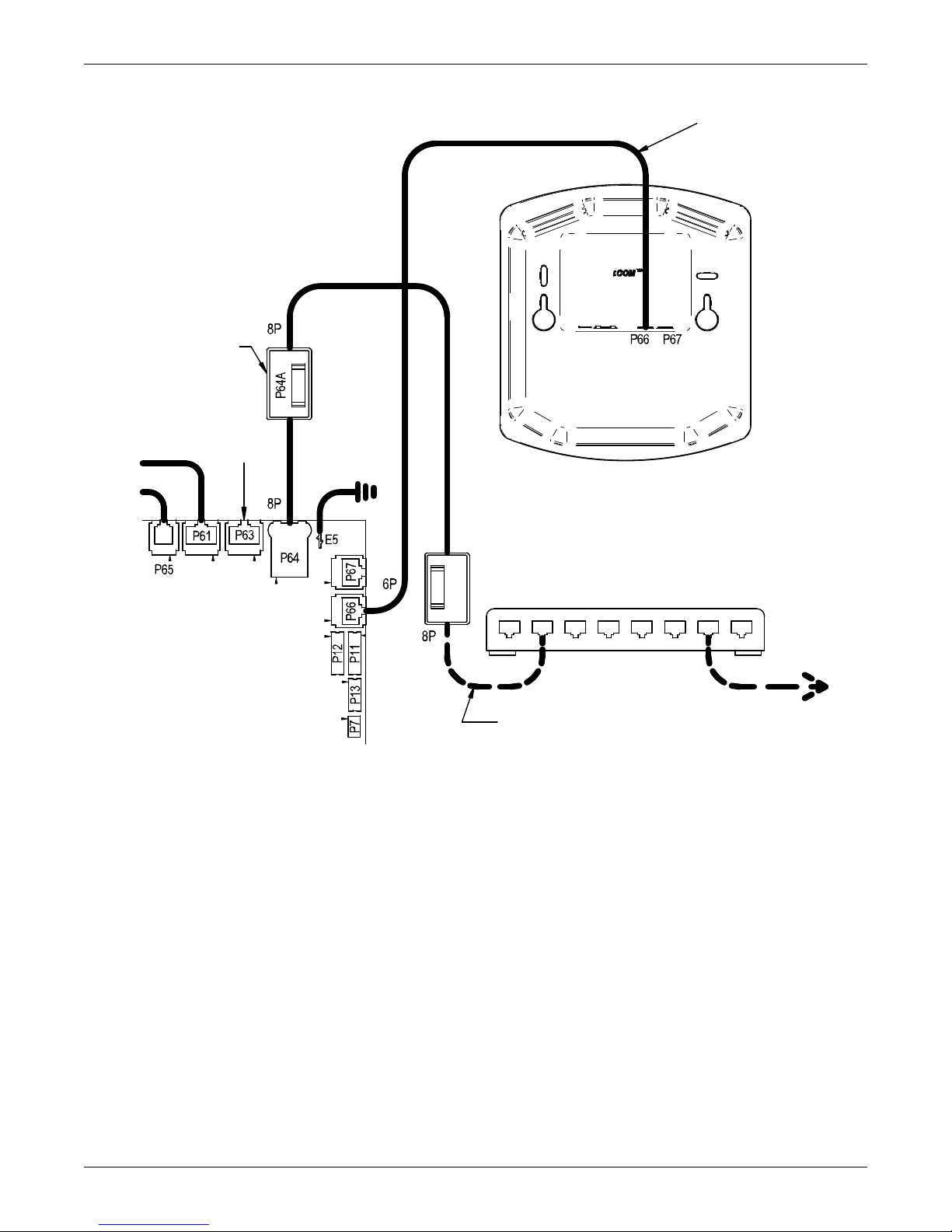
Figure 31 Wiring a small display for U2U network operation
Standard Small
Graphics Display
(Rear View)
Liebert iCOM
I/O Board
Straight-Through
Ethernet Cable
To / From Other
Networked Units
CAN
Cable
U2U Networking Switch
(Field-Supplied)
Not
Used
Cable 'C'
P64A Connection
Located Near
I/O Board
194273
Installing a Liebert iCOM Unit-to-Unit Network
49
Page 56
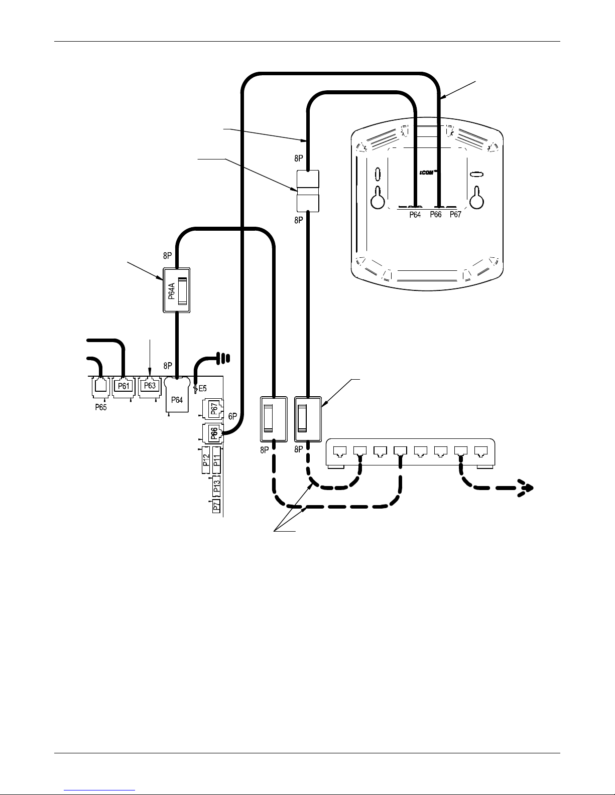
Figure 32 Wiring a large display for U2U network operation
Crossover
Coupler
(See Note 6)
Red Crossover
Ethernet Cable
Liebert iCOM
I/O Board
Straight-Through
Ethernet Cables
CAN
Cable
See Note 4
Optional Large
Graphics Display
(Rear View)
To / From Other
Networked Units
U2U Networking Switch
(Field-Supplied)
Not
Used
Customer Connection Point
See Note 6
Cable 'D'
Cable 'C'
P64A Connection
Located Near
I/O Board
194273
Installing a Liebert iCOM Unit-to-Unit Network
Liebert vNSA
The Liebert vNSA is designed to connect multiple Liebert iCOM control devices. The Liebert vNSA
contains either one or two powered industrial rail switches. An optional remote large display can be
attached to the front door as well. All models have a power supply that requires connection to a single
phase 120V or 240VAC power source. The enclosure features a key lock for security.
The Liebert vNSA supports autonegotiation, autopolarity and autocrossing, allowing for the use of
standard network cables for connection to each port, rather than special crossover cables. The switch
detects and makes adjustments for the network's speed and transmission mode, polarity and transmit-and-receive pins. See the Liebert vNSA user manual, SL-18840, for more details.
The number of ports available for connecting Liebert iCOM control devices varies by model as shown
in Table 12. Models with a remote large display attached to the front door utilize one of the available
Ethernet ports in the Liebert vNSA. Models with two switches utilize two ports to connect the
switches.
50
Page 57
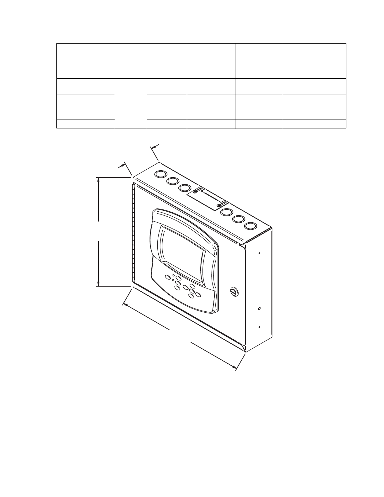
Table 12 Ports available for connecting Liebert iCOM control devices
3.298"
(84mm)
12"
(305mm)
14.25"
(362mm)
DPN001136
Rev. 0
Liebert
vNSA With
Remote
Large
Model
Liebert vNSA8-Liebert
iCOM
Liebert vNSA16-
Liebert iCOM
Liebert vNSA8
Liebert vNSA16 16 - 2 14
Display
Yes
No
Total Number
of Ports
81 - 7
16 1 2 13
8- - 8
Number of Ports
Used to Connect
Remote Large
Display
Figure 33 Liebert vNSA with optional remote large display
Installing a Liebert iCOM Unit-to-Unit Network
Number of Ports
Used to
Interconnect
Switches
Number of Ports
Available to
Connect Liebert iCOM
Control Devices
51
Page 58

External Communications—Building Management Systems, Liebert SiteScan
®
6.0 EXTERNAL COMMUNICATIONS—BUILDING MANAGEMENT SYSTEMS, LIEBERT
SITESCAN
Liebert iCOM is capable of communicating with external monitoring systems, such as Building Management Systems (BMS), Network Monitoring Systems (NMS), Liebert's SiteScan
others.
Each Liebert iCOM-controlled cooling unit is equipped with Liebert IntelliSlot plug-in slots for use
with optional communication cards:
• Ethernet Web/SNMP Card
• RS-485 Modbus Card
The hot-swappable plug-in cards provide interfaces supporting open protocols, including Modbus,
HTTP (Web) and SNMP. See the Liebert Web site for the latest supported protocols, Modbus reference information and SNMP MIBs.
An alternative, limited method of communicating with an existing Liebert SiteScan Web monitoring
system is via twisted-pair cables connected to terminals 77 and 78 on the cooling unit terminal strip.
To use this method, the Liebert IntelliSlot power supply connection to P65 on the Liebert iCOM I/O
board must be unplugged, and the factory-supplied 77-78 cable must be connected to P65 (follow Liebert SiteScan instructions for further connections). The appropriate Liebert iCOM control parameters
will also need to be configured to utilize the terminals.
®
®
Web system and
NOTE
Liebert SiteScan will be limited to legacy parameters when communicating via terminals 77
and 78.
52
Page 59
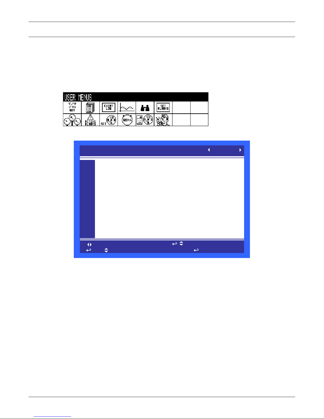
7.0 USER MENU PARAMETERS
User Menu password: 1490
SETPOINTS
to change parameter
to confirm
to select parameter
for next/previous unit
then
PASSWORD (Actual Level 0)
Temperature Setpoint
Humidity Setpoint
Humidity Control Type
Supply Sensor
Supply Setpoint
Backup Temperature Setpoint
????
73°F
50.0%
Relative
Control
50°F
73°F
UNIT 01
U101
U102
U103
U104
U105
U106
U107
U108
U109
U110
U111
User menus report general cooling unit operations and status. The user menu password is 1490.
The User menu parameter tables in this manual may differ from the display on your cooling unit. The
Liebert iCOM functions with several Liebert Precision Cooling units, each with its own set of control
commands. In addition, the Liebert iCOM control firmware is being updated constantly. As a result,
the User menu parameter tables in this manual may differ from the display on your cooling unit.
Check www.liebert.com for the latest Liebert iCOM user manual updates.
Figure 34 User menu icons
Figure 35 Setpoints parameters screen
User Menu Parameters
Temperature Setpoint—This parameter allows the user to select a temperature that the cooling
unit will maintain by applying cooling and or reheats.
Humidity Setpoint—This parameter allows the user to select a humidity that the cooling unit will
maintain by removing or adding moisture to the air.
Humidity Control Type—This parameter selects the humidity control calculation. Setting this
parameter to “Relative” will control the humidity without considering any temperature deviations.
“Predictive” and “Absolute” control consider the temperature deviation from temperature setpoint so
that a constant level of moisture is kept in the area based on the humidity sensor reading and the
temperature deviation from setpoint.
Supply Limit—This parameter allows a user to enable or disable the discharge air temperature sensor. This sensor is an optional sensor that can be ordered from the factory.
Supply Limit Temp Value—This parameter selects the minimum discharge air temperature. When
the actual sensor reading approaches this parameter the cooling capacity will be limited to avoid
going below the Supply Limit Temperature value.
Backup Temperature Setpoint—This parameter allows you to select a temperature setpoint that
will be activated in the event of a BMS time-out or a customer input signal. The BMS timer must and
/ or the customer input must be configured for this parameter to activate.
53
Page 60

Spare Part List
SET ALARMS (page 1 of 1)
to change parameter
to confirm
to select parameter
for next/previous unit
then
PASSWORD (Actual Level 0)
Return Sensor Alarms
High Return Temperature
Low Return Temperature
High Return Humidity
Low Return Humidity
Sensor A Alarms
High Temperature Sensor A
Low Temperature Sensor A
High Humidity Sensor A
Low Humidity Sensor A
????
Enable
80°F
65°F
60.0%
40.0%
Disable
°F
°F
%
%
UNIT 01
U201
U202
U203
U204
U205
U206
U207
U208
U209
U210
U211
Spare Parts—The spare parts lists contains a detailed description and part number that can be used
to order parts for the unit. These part numbers are specific to each model and option installed on the
unit.
Event Log
Event Log—The event log displays all events and actions that have been generated by the unit.
When multiple units are networked you will see the event log of the whole system. Each event shows
the unit that generated the alarm, time and date stamp, a description and the event type
View Network
View Network—The view network screen provides an overview of the Liebert iCOM network and a
status of each unit. This screen will provide the unique unit name given to the unit. If no name is
given, then only the unit number will be displayed.
Figure 36 Set alarms screen
User Menu Parameters
Return Sensor Alarms—This parameter enables or disables the return sensor alarms. When
enabled the return temperature and humidity values will be compared to a high and low setting.
High Return Temperature—This parameter is visible when the return sensor alarm is enabled.
When enabled the high temperature alarm allows a user to adjust the point at which the actual
return temperature activates a High Temperature Alarm.
Low Return Temperature—This parameter is visible when the return sensor alarm is enabled.
When enabled the low temperature alarm allows a user to adjust the point at which the actual return
temperature activates a Low Temperature Alarm.
High Return Humidity—This parameter is visible when the return sensor alarm is enabled. When
enabled the high humidity alarm allows a user to adjust the point at which the actual return humidity activates a High Humidity Alarm.
Low Return Humidity—This parameter is visible when the return sensor alarm is enabled. When
enabled the low humidity alarm allows a user to adjust the point at which the actual return humidity
activates a Low Humidity Alarm.
Sensor A Alarms—This parameter enables or disables the alarms for reference sensor A. When
enabled the sensor A temperature and humidity values will be compared to a high and low setting.
High Temperature Sensor A—This parameter is visible when the sensor A alarm is enabled. When
enabled the high temperature alarm allows a user to adjust the point at which the actual sensor A
temperature activates a High Temperature Alarm.
54
Page 61

User Menu Parameters
Low Temperature Sensor A—This parameter is visible when the sensor A alarm is enabled. When
enabled the low temperature alarm allows a user to adjust the point at which the actual sensor A temperature activates a Low Temperature Alarm
High Humidity Sensor A—This parameter is visible when the sensor A alarm is enabled. When
enabled the high humidity alarm allows a user to adjust the point at which the actual sensor A
humidity activates a High Humidity Alarm
Low Humidity Sensor A—This parameter is visible when the sensor A alarm is enabled. When
enabled the low humidity alarm allows a user to adjust the point at which the actual sensor A humidity activates a Low Humidity Alarm
55
Page 62

Figure 37 Sensor data screen
SENSOR DATA (page 1 of 2)
to select parameter
Optional Sensor A 1
Optional Sensor A 2
Optional Sensor B 1
Optional Sensor B 2
Optional Sensor C 1
Optional Sensor C 2
Freecooling Fluid Temperature
Outdoor Temperature
Freecooling Status
DigiScroll 1 Temperature
DigiScroll 2 Temperature
72°F
49.5%
°F
°F
°F
°F
°F
°F
°F
°F
°F
UNIT 01
U301
U302
U303
U304
U305
U306
U307
U308
U309
U310
U311
U312
This window is READ ON LY
Optional Sensor A1—When a optional reference sensor is connected to the Liebert iCOM controller
area network (CAN) bus the sensor A temperature value will be shown. A reference sensor can be connected to any type of Liebert iCOM unit.
User Menu Parameters
Optional Sensor A2—When a optional reference sensor is connected to the Liebert iCOM controller
area network (CAN) bus the sensor A humidity value will be shown. A reference sensor can be connected to any type of Liebert iCOM unit.
Optional Sensor B1—When a optional reference sensor is connected to the Liebert iCOM controller
area network (CAN) bus the Sensor B temperature value will be shown. A reference sensor can be
connected to any type of Liebert iCOM unit.
Optional Sensor B2—When a optional reference sensor is connected to the Liebert iCOM controller
area network (CAN) bus the Sensor B humidity value will be shown. A reference sensor can be connected to any type of Liebert iCOM unit.
Optional Sensor C1—When a optional reference sensor is connected to the Liebert iCOM controller
area network (CAN) bus the sensor C temperature value will be shown. A reference sensor can be connected to any type of Liebert iCOM unit.
Optional Sensor C2—When a optional reference sensor is connected to the Liebert iCOM controller
area network (CAN) bus the sensor C humidity value will be shown. A reference sensor can be connected to any type of Liebert iCOM unit.
Freecooling Fluid Temperature—If a unit is equipped with a freecooling coil then this parameter
displays the temperature of the incoming water.
Outdoor Temperature—This parameter reads the outdoor temperature for freecooling and dual
cool units to determine if cooling can be provided without compressor operation. Only available on
HPM units.
Freecooling Status—This parameter displays if freecooling is available for use based on the return
air temperature and the incoming fluid temperature.
Digital Scroll 1 Temperature—When digital scroll compressors are installed in the unit then the
actual digital scroll number 1 head temperature will be shown.
Digital Scroll 2 Temperature—When digital scroll compressors are installed in the unit then the
actual digital scroll number 2 head temperature will be shown.
56
Page 63

Figure 38 Sensor data screen - Page 2 (return only)
SENSOR DATA (page 2 of 2)
to select parameter
Daily H igh Temperature
Daily Low Temperature
Daily High Humidity
Daily Low Humidity
73°F
66°F
48.5%
48.3%
UNIT 01
U313
U314
U315
U316
U317
U318
U319
U320
U321
U322
U323
U324
This window is READ ON LY
13:59:31
08:04:38
08:16:11
08:03:47
Daily High Temperature—The daily high temperature is the highest recorded temperature from
12:00am to 11:59pm.
User Menu Parameters
Daily Low Temperature—The daily low temperature is the lowest recorded temperature from
12:00am to 11:59pm.
Daily High Humidity—The daily high humidity is the highest recorded humidity from 12:00am to
11:59pm.
Daily Low Humidity—The daily low humidity is the lowest recorded humidity in the last 24 hour
period.
Active Alarms
Active Alarms—Permits viewing all current, active alarms.
57
Page 64

Figure 39 Display setup parameters screen
DISPLAY SETUP
to change parameter
to confirm
to select parameter
for next/previous unit
then
Language
Date
Time
Temperature Indication
Display Contrast
Buzzer Frequency
Backlite Off after
Screen
Display Shows
Display Colors
Date Format
ENGLISH
7/3/2010
14:01:49
°F
45
Off/ 0
12h
Graphical C omma
ACT+SET
Normal
mm/dd/yyy
SYSTEM
U401
U402
U403
U404
U405
U406
U407
U408
U409
U410
U411
Language—This parameter sets the language on the display. When this parameter is changed all
menu parameters will be converted to the selected language.
User Menu Parameters
Date—This parameter sets the internal date of the unit. If this unit is connected to other units with
the unit to unit network connection. All units will reflect the last date set.
Time—This parameter sets the internal time of the unit. If this unit is connected to other units with
the unit to unit network connection. All units will reflect the last time set.
Temperature Indication—This parameter selects the actual and set point temperature indication.
Selecting C will set the unit to display in Celsius and F will set the unit to display in Fahrenheit.
Display Contrast—This parameter changes the contrast of the display to adjust for different viewing angles, low light and bright light conditions. As the display ages the contrast may need to be
adjusted for better viewing clarity.
Buzzer Frequency—This parameter changes the audible noise frequency of the built in buzzer.
When adjusting the buzzer frequency the buzzer will sound allowing you to select a frequency that is
easily detected when an alarm occurs.
Backlite Off After X Hours—This parameter controls the length of time that the backlite remains
active when the display is unused. When the buttons on the front display have not been pressed for
the time selected in this parameter the backlite will turn off, extending the life of the display and saving energy.
Display Shows—This parameter selects if the main display shows the temperature and humidity
actual values only setpoint values only or both actual and set point.
Display Colors—This parameter selects the background color. Inverted sets the display to show
white font with blue background and Normal sets a white background with blue font.
Date Format—Date format changes the month, day and year arrangement shown on the front display and event time stamps.
58
Page 65
Figure 40 Total run hours parameters screen
TOTAL RUN HOURS
to change parameter
to confirm
to select parameter
for next/previous unit
then
Fan Motor ( s)
Compressor 1
Compressor 2
Chilled Water/Free Cool
Hot Gas / HotWater
Electric H eater1
Electric H eater 2
Electric H eater 3
Humidifier
Dehumidification
Limit
0
0
0
0
0
0
0
0
0
0
SYSTEM
U501
U502
U503
U504
U505
U506
U507
U508
U509
U510
U511
Actual Hours
28
9
9
0
0
1
0
0
0
1
SLEEP MODE
to change parameter
to confirm
to select parameter
for next/previous unit
then
PASSW ORD (Actual Level 0)
Sleep On :
Sleep Every day (1)
From:
Sleep Every day (2)
From:
Timer Mode
Timer Mode Type
Dead Band
????
MON TUE WED THU FRI SAT SUN
No No No No No No No
00:00 to 00:00
00:00 to 00:00
Yes
SYSTEM OFF
°F
U601
U602
U603
U604
U605
U606
U607
U608
U609
U610
U611
UNIT 01
Figure 41 Sleep mode parameters screen
User Menu Parameters
59
Page 66
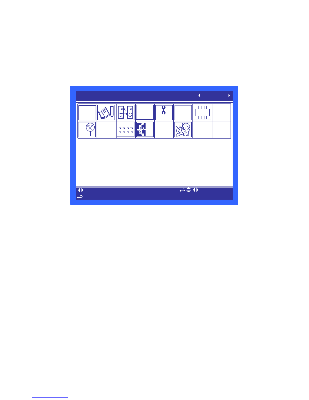
8.0 SERVICE MENU PARAMETERS
°C / °F
% RH
SET
SERVICE MENUS
to select parameter
UNIT 01
to change level
to open requested menu
ESC
to unselect
to navigate
+
WELLNESS
SET
ALARMS
DO
SERVIC E
+/-
NETWORK
SET
UP
Service menus allow customized settings for site operations. The password for service menu parameters is 5010.
The Liebert iCOM control firmware is being updated constantly. As a result, the Service menu
parameter tables shown in this manual may be slightly different than what is shown on your cooling
unit's display. Please check www.liebert.com for the latest Liebert iCOM User manual updates.
Figure 42 Service Menu Main Screen
Service Menu Parameters
60
Page 67

Figure 43 Setpoints parameters screen - Page 1
SETPOINTS (pg 1 of 6 )
to change parameter
to confirm
to select parameter
for next/previous unit
then
UNIT 01
PASSWORD (Actual Level 0)
Temperature Setpoint
Control Type
Temperature Proportional Band
Temperature Integration Time
AutoSet Enable
Temperature DeadBand
Second Setpoint
Backup Temperature Setpoint
Heaters DeadBand
????
73°F
Proportional
5°F
min
No
0°F
73°F
73°F
°F
S101
S102
S103
S104
S105
S106
S107
S108
S109
S110
S111
Temperature Setpoint—This parameter selects a temperature that the cooling unit will maintain
by applying cooling and or reheats. This parameter is adjustable from 41-104°F (5-40°C), the factory
default setting is 73°F (22.7°C).
Service Menu Parameters
Control Type—This parameter selects the type of control the system will use to activate cooling,
heating, humidification and dehumidification. A detailed description of each control type can be found
in 3.7 - Supply Control.
Temperature Proportional Band—This parameter adjusts the activation points of compressors or
rate of change based on the actual sensor values deviation from setpoint. The smaller this number the
faster the compressors and valve(s) will increase capacity. Too small of a number may cause the unit
to short cycle the compressors or excessively reposition the valve.
Temperature Integration Time—This parameter adjusts the capacity of the unit based on time
away from setpoint so that accurate temperature control can be maintained. This parameter is only
active when Control Type is set to “PI”.
AutoSet Enable—When this parameter is set to “YES” the temperature and humidity proportional
bands will automatically be set based on the type of unit and if teamwork modes are selected. To
change the proportional bands this parameter must be set to “NO”.
Temperature Deadband—This parameter can be set to avoid overshooting of the setpoint and
cycling between the reheats and cooling. The value entered into this field will be split in half by the
temperature setpoint. Example—If the temperature setpoint is 70°F (21.1°C) and a 4°F (2.2°C) deadband is set, then no cooling will be activated until 72°F (22.2°C) and no heating will be activated until
68°F (20°C) is reached.
Second Setpoint—This parameter will select a temperature setpoint that will be activated in the
event of a customer input signal configured as the 2nd Setpoint. The customer input must be configured for this parameter to activate. This parameter is adjustable from 41-104°F (5-40°C). The factory
default setting is 73°F (22.7°C).
Backup Temperature Setpoint—This parameter will select a temperature setpoint that will be
activated in the event of a BMS Timeout. The BMS timer must be configured for this parameter to
activate. This parameter is adjustable from 41-104°F (5-40°C). The factory default setting is 73°F
(22.7°C).
Heaters Deadband—On HPM units, this parameter changes the amount of deviation below the
temperature setpoint that the heaters will cycle On and Off. This parameter value is added to the
heating side of the normal temperature deadband.
61
Page 68

Figure 44 Setpoints parameters screen - Page 2
SETPOINTS (pg 2 of 6 )
to change parameter
to confirm
to select parameter
for next/previous unit
then
UNIT 01
PASSWORD (Actual Level 0)
Humidity Setpoint
Humidity Control Type
Humidity Proportional Band
Humidity Integration Time
Humidity DeadBand
Dehum/Heat Low Limit 1
Dehum/Heat Low Limit 2
????
50%
Relative
10.0%
0min
0.0%
-3°F
-7°F
S112
S113
S114
S115
S116
S117
S118
S119
S120
S121
S122
Humidity Setpoint—This parameter allows the user to select a humidity that the cooling unit will
maintain by removing or adding moisture to the air. This parameter is adjustable from 20-80%. The
factory default setting from the factory is 50%.
Service Menu Parameters
Humidity Control Type—This parameter selects the humidity control calculation. Setting this
parameter to “Relative” will control the humidity without considering any temperature deviations.
“Predictive” and “Absolute” control consider the temperature deviation from temperature setpoint so
that a constant level of moisture is kept in the area based on the humidity sensor reading and the
temperature deviation from setpoint. The factory default setting is “Predictive.”
Humidity Proportional Band—This parameter adjusts the activation points of the humidifier and
compressors based on the actual sensor values deviation from setpoint. The smaller this number the
faster the compressors and humidifier will increase capacity, too small of a number may cause the
unit to short cycle or overshoot setpoint.
Humidity Integration Time—This parameter adjusts the capacity of the unit based on time away
from setpoint so that accurate humidity control can be maintained. This parameter is only active
when Control Type is set to “PI.”
Humidity Deadband—This parameter can be set to avoid overshooting of the setpoint and cycling
between humidification and dehumidification. The value entered into this field will be split in half by
the temperature setpoint. Example: If the humidity setpoint is 50% and a 4% deadband is set then no
humidity control will be activated between 48% and 52%.
Dehum/Heat Low Limit 1—This parameter sets the temperature at which 1 of 2 compressors will
be deactivated for dehumidification control. Unit must be set for 2 compressor dehumidification for
this value to be settable. Example—If low limit 1 is set to 4°F (2.2°C) and the temperature setpoint is
70°F (21.1°C) then one of the 2 compressors will turn off at 66°F (18.8°C).
Dehum/Heat Low Limit 2—This parameter sets the temperature at which all dehumidification is
stopped. Example—If low limit 2 is set to 8°F (4.4°C) and the temperature setpoint is 70°F (21.1°C)
then all dehumidification will be deactivated at 62°F (16.6°C).
62
Page 69

Figure 45 Setpoints parameters screen - Page 3
SETPOINTS (pg 3 of 6 )
to change parameter
to confirm
to select parameter
for next/previous unit
then
UNIT 01
PASSWORD (Actual Level 0) ????
Supply Sensor Control
Supply Setpoint 50°F
Supply Control Type Proportional
Supply Proportional Band 12°F
Supply Integration min
Supply DeadBand 0°F
Valve Pulse 3%
Cooling Filter at 0% / 100% / 100.00 / 100%/s
Return Compensation 5°F
S123
S124
S125
S126
S127
S128
S129
S130
S131
S132
S133
Supply Sensor—This parameter selects how the supply sensor will be used by the control. The selections for this parameter are Disabled, Cooling Only, Control and Limit. See 3.8 - Event Types and
Properties for a detailed description. The supply sensor can only be set to Cooling Only and Control
on chilled water units. The chilled water unit must have the valve feedback if the valve type is a 3P
valve (stem). Motorized ball valves do not require the feedback feature.
Supply Setpoint—This parameter sets the temperature setpoint for the supply sensor when it is set
to Cooling Only, Control or Limit.
Supply Control Type—This parameter selects the type of control the system will use to activate
cooling. A detailed description of each control type can be found in 3.7 - Supply Control.
Supply Proportional Band—When the supply sensor is set to Cooling Only or Control then this
parameter adjusts the valves rate of change based on the actual sensor values deviation from setpoint. The smaller this number the faster the valve(s) will increase cooling capacity. Too small of a
number may cause the unit to excessively reposition the valve.
Supply Integration—This parameter adjusts the capacity of the unit based on time away from setpoint so that accurate temperature control can be maintained. This parameter is only active when
Control Type is set to “PI.”
Supply Deadband—This parameter can be set to avoid overshooting of the setpoint and cycling
between the reheats and cooling. The value entered into this field will be split in half by the temperature setpoint. Example: If the temperature setpoint is 60°F (15.5°C) and a 4°F (2.2°C) deadband is set
then no cooling will be activated until 62°F (16.6°C) and no heating will be activated until
58°F (14.4°C) is reached.
Valve Pulse—This parameter defines the minimum change in the cooling requirement before the
valve will reposition. A greater number decreases the amount of repositions and a smaller number
will increase the response of the valve.
Cooling Filter at 0% / 100%—This parameter filters the controls reaction in order to avoid overshoots. The filter value depends on the current control deviation. On setpoint (at 0%), it’s typically set
lower (slow), and at the end of the p-band (at 100%), it’s typically set higher (faster). The value is
given in % control output change per second.
Return Compensation—for supply control only. This parameter defines the maximum increase
allowed to the supply temperature setting to maintain a return temperature setpoint. When the
return air temperature is above its setpoint and p-band, the supply air setpoint remains unchanged.
As the return air temperature approaches the setpoint, the supply air setpoint will be proportionally
increased to maintain the return temperature setpoint. The maximum increase is defined with the
return compensation parameter.
Service Menu Parameters
63
Page 70

Figure 46 Setpoints parameters screen - Page 4
SETPOINTS (pg 4 of 6 )
to change parameter
to confirm
to select parameter
for next/previous unit
then
UNIT 01
PASSWORD (Actual Level 0) ????
DT between Room / Outdoor Type Disable
DT between Room Air / Outdoor °F
DT between Room / FC Type Disable
DT between Room Air FC Fluid °F
Minimum CW Temp Disable
Minimum CW Temp Value °F
Lock out FC at FC Fluid below 48°F
Transition Change 100 .0%
S134
S135
S136
S137
S138
S139
S140
S141
S142
S143
S144
DT between Room / Outdoor Type—This feature is only used on HPM products.
Service Menu Parameters
DT between Room Air / Outdoor—This feature is only used on HPM products.
DT between Room / FC Type—This parameter determines the method to activate the water circuit
on Dual Cool and Freecool units. When set to “Contact” a dry contact closure can be used to activate
the free cooling circuit. When set to “Value” the delta between the water temperature of the freecool
circuit and the actual room temperature are compared.
DT between Room Air / FC Fluid—This parameter sets the delta between the actual room temperature and the free cooling fluid temperature to determine if cooling can be provided.
Minimum CW Temp—This parameter enables the temperature at which freecooling can operate
independently without assistance of the compressor circuit.
Minimum CW Temp Value—This parameter sets the water temperature at which 100% freecooling
can be provided to handle the full room load. When the fluid temperature is below this setting then
the compressors will no longer turn on until the water temperature is above the minimum CW Temp.
Lockout FC at FC Fluid below—This parameter is the temperature that turns off the freecooling
circuit when the water temperature is too low. This setting prevents frost from building up on the
freecooling pipes when the outdoor ambient is extremely low.
Transition Change—This parameter is applied over the “Cooling Filter at 0% / 100%” when the
cooling signal goes to / comes from dehumidification. This will smooth the cooling capacity changes
between dehumidification and cooling.
64
Page 71

Figure 47 Setpoints parameters screen - Page 5
SETPOINTS (pg 5 of 6 )
to change parameter
to confirm
to select parameter
for next/previous unit
then
UNIT 01
PASSWORD (Actual Level 0) ????
VSD Fanspeed Delta
VSD Setpoint STD 100%
VSD Setpoint MIN 60%
VSD Setpoint Dehum 60%
VSD Setpoint No Power 100%
Fanspeed Change 0.20 / 1.00%/s
Fanspeed Reposition Delay 0sec
Fanspeed Delta 34°F
Fanspeed P -Band 36°F
Fanspeed Integration 5min
S145
S146
S147
S148
S149
S150
S151
S152
S153
S154
S155
VSD Fanspeed—This parameter sets the control type for a variable fanspeed device which includes
Variable Frequency Drives and EC Fans. Selection options are Auto, Manual, Economy and Delta
control. See section 3.1.1 for details of each control.
Service Menu Parameters
VSD Setpoint STD—When VSD Fanspeed parameter is set to Auto, Economy or Delta control then
this parameter is the high limit for the fan speed output. If VSD Fanspeed is set to Manual then this
parameter is the actual running speed of the fan.
VSD Setpoint MIN—This parameter is the minimum speed that the fan will operate. Fan speed is
modulated between the “VSD Setpoint MIN” and “VSD Setpoint STD”.
VSD Setpoint Dehum—This parameter sets the fixed fan speed the fan will operate at when there is
a call for dehumidification. The factory default setting is 60% which helps to keep the coil in a latent
or dehumidification mode.
VSD Setpoint No Power—This parameter sets the fan speed when a Customer Input set to “No
Power” is activated.
Fanspeed Change at 0% / 100%—This parameter filters the control’s reaction in order to avoid
overshoots. The filter value depends on the current control deviation. On setpoint (at 0%), it’s typically set lower (slow), and at the end of the p-band (at 100%), it’s typically set higher (faster). The
value is given in % control output change per second.
Fanspeed Reposition Delay—This parameter sets the reposition delay that is applied only for
changes to decrease fanspeed; increases in fanspeed are controlled only by the fanspeed change speed
filter. After fanspeed is increased, the timer will prevent the speed from being reduced for the delay
duration.
Fanspeed Delta—This parameter sets the temperature delta between the two Cold Aisle Containment sensors. This delta is maintained to ensure that there is sufficient airflow inside of the containment area.
Fanspeed P-Band—This parameter adjusts the fans rate of change based on the actual sensor values deviation from setpoint or the delta. The smaller this number the faster the fan will increase its
speed. Too small of a number may cause the fans to excessively reposition.
Fanspeed Integration—This parameter adjusts the fanspeed of the unit based on time away from
setpoint. This parameter is only active when Control Type is set to “PI.”
65
Page 72
Figure 48 Setpoints parameters screen - Page 6
SETPOINTS (pg 6 of 6 )
to change parameter
to confirm
to select parameter
for next/previous unit
then
UNIT 01
PASSWORD (Actual Level 0) ????
SCR C ontrol Type
Start Compressor 1 At %
Stop Compressor 1 At %
Compressor 1 Stop Delay min
Start Compressor 2 At %
Stop Compressor 2 At %
Compressor 2 Stop Delay min
Cycle Time sec
SCR Factor
Actual SCR Request %
S156
S157
S158
S159
S160
S161
S162
S163
S164
S165
S166
SCR Control Type—This parameter sets the control type for the SCR re-heats. If set to “Standard”
then the re-heats will modulate when the temperature is below setpoint based on the control settings.
If this parameter is set to “Tight” control then one compressor will be locked on and the re-heats will
modulate to offset the cooling capacity.
Service Menu Parameters
Start Compressor 1 / 2 at—This parameter can be used when set to “Tight” control. It sets the activation point of the compressor.
Stop Compressor 1 / 2 at—This parameter can be used when set to “Tight” control. It sets the deactivation point of the compressor.
Compressor 1 / 2 stop delay—This parameter sets the delay when the stop compressor setpoint is
met.
Cycle time—This parameter is set from factory and should only be changed by an authorized Liebert
representative.
SCR Factor—This parameter is set from factory and should only be changed by an authorized Liebert representative.
Unit Diary—Large Display Only
Shows all entered program changes and maintenance performed on the unit.
Table 13 Unit diary parameters
Function
Large Display Small Display
Page 1 of 1
Text entered with iST
(Liebert iCOM Service Tool)
N/A -
Range
Imperial (metric)
66
Page 73

Figure 49 Standby settings / lead-lag parameters screen
STANDBY SETTINGS / LEAD-LAG
to change parameter
to confirm
to select parameter
for next/previous unit
then
SYSTEM
PASSWORD (Actual Level 0) ????
Number of Standby Units 0
Rotation Frequency No
Rotate at (hour) 00
Rotate at (minute) 00
Rotate by 1
Perform one R otation No
Cascade Units No
Start all Standby Units by HT No
S501
S502
S503
S504
S505
S506
S507
S508
S509
S510
S511
Number of Standby Units—This parameter selects the number of units that will be in Standby
mode. When a unit is in standby mode the fan will be off and no cooling will be provided.
Service Menu Parameters
Rotation Frequency—This parameter controls when a rotation will occur between the standby
units and the operating units within a network.
Rotate at (hour)—This parameter sets the hour of the rotation
Rotate at (minute)—This parameter sets the minute of the rotation
Rotate by—This parameter determines the number of positions to rotate by. Example: If there are 6
units in a unit to unit network and units 1, 3 & 5 are in standby and this parameter is set to “1” then
at the next rotation units 2, 4,& 6 will be placed into standby and 1, 3 & 5 will become operational.
Cascade Units—This parameter when set allows units to activate from Standby mode if the room
temperature is unable to be maintained by the non-standby units. If yes is selected then the cascade
units can perform all functions when activated from standby. This parameter can also be set for Cooling Only or Cool / Heat only.
Start all Standby Units by HT—This parameter activates all units to cool when a High Temperature alarm occurs.
See 3.9.1 - Calculation of Next Maintenance and Diagnostics for details on these menus.
67
Page 74

Figure 50 Wellness basic settings screen- Page 1
WELLNESS basic settings (page 1 of 8)
to change parameter
to confirm
to select parameter
for next/previous unit
then
SYSTEM
PASSWORD (Actual Level 0) ????
Maintenance Frequency Per Year 1
Max Bonus 0
Max Penalty 0
Last Maintenance 08/17/2010
Service Engineer N OBODY
Confirm PM No
Calculated Next Maintenance 08 /2011
S001
S002
S003
S004
S005
S006
S007
S008
S009
S010
S011
Maximum Frequency Per year—This parameter sets the number of expected maintenance visits
in a one year time span.
Service Menu Parameters
Max Bonus—This parameter will increase the time to the next maintenance cycle. A bonus should be
assigned when a service visit finds that all components are working optimally.
Max Penalty—This parameter will decrease the time to the next maintenance cycle. A penalty
should be used when a service visit finds excessive wear on components.
Last Maintenance—This parameter is set during the service call. It also indicates to other service
personnel the date of the last visit.
Service Engineer—This parameter provides a label for the service representative to list either the
company name or representative’s name.
Confirm PM—This parameter confirms that the service representative has completed the preventive
maintenance and resets the next maintenance date.
Calculated Next Maintenance—This parameter provides a date to when the next expected maintenance should take place based on the last confirmed PM, component starts, run hours and the
penalty / bonus currently set in the Liebert iCOM control.
68
Page 75
Figure 51 Wellness motor settings parameters screen - Page 2
WELLNESS motor settings (page 2 of 8 )
to change parameter
to confirm
to select parameter
for next/previous unit
then
PASSWORD (Actual Level 0) ????
Number of Starts 7
Run Hours 22hrs
Average Run Time 188min
Starts per Day Best 1
Starts per Day W orst 24
Number of Alarms 0
Actual Bonus 0
S012
S013
S014
S015
S016
S017
S018
S019
S020
S021
S022
UNIT 1
WELLNESS compressor1 settings (page 3 of 8)
to change parameter
to confirm
to select parameter
for next/previous unit
then
PASSWORD (Actual Level 0) ????
Number of Starts 3
Run Hours 7hrs
Average Run Time 140min
Starts per Day Best 12
Starts per Day W orst 240
Number of HP Alarms 0
Number of LP Alarms 0
Number of OL Alarms 0
Number of DS HT Alarms 0
Actual Bonus 0
S023
S024
S025
S026
S027
S028
S029
S030
S031
S032
S033
UNIT 1
Figure 52 Wellness compressor 1 settings parameters screen - Page 3
Service Menu Parameters
69
Page 76
Figure 53 Wellness compressor 1 settings parameters - Page 4
WELLNESS compressor2 settings (page 4 of 8)
to change parameter
to confirm
to select parameter
for next/previous unit
then
PASSWORD (Actual Level 0) ????
Number of Starts 3
Run Hours 7hrs
Average Run Time 140min
Starts per Day Best 12
Starts per Day W orst 240
Number of HP Alarms 0
Number of LP Alarms 0
Number of OL Alarms 0
Number of DS HT Alarms 0
Actual Bonus 0
S034
S035
S036
S037
S038
S039
S040
S041
S042
S043
S044
UNIT 1
WELLNESS el heater 1 settings (page 5 of 8)
to change parameter
to confirm
to select parameter
for next/previous unit
then
PASSWORD (Actual Level 0) ????
Number of Starts 0
Run Hours 0hrs
Average Run Time 0min
Starts per Day Best 24
Starts per Day W orst 240
Number of HP Alarms 0
Actual Bonus 0
S045
S046
S047
S048
S049
S050
S051
S052
S053
S054
S055
UNIT 1
Figure 54 Wellness electric heater 1 settings parameters screen - Page 5
Service Menu Parameters
70
Page 77
Figure 55 Wellness electric heater 2 settings parameters screen - Page 6
WELLNESS el heater 2 settings (page 6 of 8)
to change parameter
to confirm
to select parameter
for next/previous unit
then
PASSWORD (Actual Level 0) ????
Number of Starts 1
Run Hours 0hrs
Average Run Time 0min
Starts per Day Best 24
Starts per Day W orst 240
Number of HP Alarms 0
Actual Bonus 0
S056
S057
S058
S059
S060
S061
S062
S063
S064
S065
S066
UNIT 1
WELLNESS el heater 3 settings (page 7 of 8)
to change parameter
to confirm
to select parameter
for next/previous unit
then
PASSWORD (Actual Level 0) ????
Number of Starts 1
Run Hours 0hrs
Average Run Time 0min
Starts per Day Best 24
Starts per Day W orst 240
Number of HP Alarms 0
Actual Bonus 0
S067
S068
S069
S070
S071
S072
S073
S074
S075
S076
S077
UNIT 1
Figure 56 Wellness electric heater 3 settings parameters screen - Page 7
Service Menu Parameters
71
Page 78

Figure 57 Wellness humidifier settings parameters screen - Page 8
WELLNESS humidifier settings (page 8 of 8)
to change parameter
to confirm
to select parameter
for next/previous unit
then
PASSWORD (Actual Level 0) ????
Number of Starts 1
Run Hours 0hrs
Average Run Time 0min
Starts per Day Best 24
Starts per Day W orst 240
Number of Alarms 0
Actual Bonus 0
S078
S079
S080
S081
S082
S083
S084
S085
S086
S087
S088
UNIT 1
Service Menu Parameters
72
Page 79

Figure 58 Diagnostics / service mode parameters screen - Page 1
DIAGNOSTICS / SERVICE MODE (page 1 of 7)
to change parameter
to confirm
to select parameter
for next/previous unit
then
PASSWORD (Actual Level 0) ????
HP 1 Alarm Code 0
HP 2 Alarm Code 0
HT 1 Alarm Counter 0
HT 2 Alarm Counter 0
LP 1 Alarm Code 0
LP 1 Alarm Code 0
Actual LP 1 Pressure psia
Actual LP 2 Pressure psia
Actual H P1 Pressure psia
Actual H P2 Pressure psia
S301
S302
S303
S304
S305
S306
S307
S308
S309
S310
S311
UNIT 01
HP 1 Alarm Code—Compressor 1 high pressure alarm code.
HP 2 Alarm Code—Compressor 2 high pressure alarm code.
Service Menu Parameters
HT 1 Alarm Counter—Compressor 1 high temperature event alarm counter. If more than
fiveevents in a rolling 4 hour period occur then the compressor will be locked out.
HT 2 Alarm Counter—Compressor 2 high temperature event alarm counter. If more than five
events in a rolling 4 hour period occur then the compressor will be locked out.
LP 1 Alarm Code—Indicates which phase compressor 1 is operating in. For more information on
this refer to the Liebert iCOM Training and Service manual’s low pressure transducer flow chart.
LP 2 Alarm Code—Indicates which phase compressor 2 is operating in. For more information on
this refer to the Liebert iCOM Training and Service manual’s low pressure transducer flow chart.
Actual LP1 Pressure—Current refrigerant low pressure side reading in atmosphere for
Compressor 1.
Actual LP2 Pressure—Current refrigerant low pressure side reading in atmosphere for
Compressor 2.
Actual HP1 Pressure—Current refrigerant high pressure side liquid reading in atmosphere for
Compressor 1. (This is available only on water cooled units equipped with motorized ball valves.)
Actual HP2 Pressure—Current refrigerant high pressure side liquid reading in atmosphere for
Compressor 2. (This is available only on water-cooled units equipped with motorized ball valves.)
73
Page 80

Figure 59 Diagnostics / service mode parameters screen - Page 2
DIAGNOSTICS / SERVICE MODE (page 2 of 7)
to change parameter
to confirm
to select parameter
for next/previous unit
then
PASSWORD (Actual Level 0) ????
Manual Mode No
Motors On
Compressor 1 Run Off
Compressor 1 Capacity Off
Compressor 1 Cycle Ramp 0%
Compressor 1 LLSV Off
Compressor 2
Compressor 2 Capacity
Compressor 2 Cycle Ramp %
Compressor 2 LLSV
S312
S313
S314
S315
S316
S317
S318
S319
S320
S321
S322
UNIT 01
Manual Mode—Use this setting to place the Liebert iCOM control in manual mode. This is the initial setting necessary to activate any of the following items.
Motor(s)—Setting this option to ON will start the main fan of the unit. Note that the main fan must
be On in order to activate any of the following overrides.
Service Menu Parameters
Compressor 1—Use this setting to turn on compressor 1 and select the mode of compressor operation. The operation selections are RUN, EVACUATE and CHARGE.
Compressor 1 Capacity—Use this setting to enable Compressor 1 Cycle Ramp.
Compressor 1 Cycle Ramp—This setting allows the user to select the capacity the compressor
should run at. Range on this is 0 – 100%.
Compressor 1 LLSV—This option will control the liquid line solenoid valve for compressor 1.
Compressor 2—Use this setting to turn on compressor 2 and select the mode of compressor opera-
tion. The operation selections are RUN, EVACUATE and CHARGE
Compressor 2 Capacity—Use this setting to enable Compressor 2 Cycle Ramp.
Compressor 2 Cycle Ramp—This setting allow the user to select the capacity the compressor
should run at. Range on this is 0 – 100%.
Compressor 2 LLSV—This option will control the liquid line solenoid valve for compressor 2.
74
Page 81

Figure 60 Diagnostics / service mode parameters screen - Page 3
DIAGNOSTICS / SERVICE MODE (page 3 of 7)
to change parameter
to confirm
to select parameter
for next/previous unit
then
PASSWORD (Actual Level 0) ????
Electric Heat 1 (or HG/HW) Off
Electric Heat 2 (or E .Heat 1 ) Off
Electric Heat 3 (or E .Heat 2 ) Off
SCR Heat %
Dehumidification Output Off
Humidifier Fill Off
Humidifier Off
Humidifier D rain
Humidifier C urrent 0.00A
S323
S324
S325
S326
S327
S328
S329
S330
S331
S332
S333
UNIT 01
Electric Heat 1 (or HG/HW)—This will activate stage 1 of the unit’s reheat system.
Electric Heat 2 (or HG/HW)—This will activate stage 2 of the unit’s reheat system.
Service Menu Parameters
Electric Heat 3 (or HG/HW)—This will activate stage 3 of the unit’s reheat system.
SCR Heat—For units using silicone controlled rectifier type reheat this setting allows the user to
specify the pulse width the heating system should run at.
Dehumidification Output—This activates the dehumidification cycle.
Humidifier Fill—This activates just the humidifier water source solenoid valve which fills the
humidifier pan or canister with water.
Humidifier—This activates the humidifier system in its entirety.
Humidifier Drain—This activates just the humidifier drain solenoid in the case of the steam gener-
ating humidifier, allowing water to drain from the canister.
Humidifier Current—In the case of the steam generating humidifier option this setting show the
amount of AC amperes the system is consuming.
75
Page 82

Figure 61 Diagnostics / service mode parameters screen - Page 4
DIAGNOSTICS / SERVICE MODE (page 4 of 7)
to change parameter
to confirm
to select parameter
for next/previous unit
then
PASSWORD (Actual Level 0) ????
Alarm Relay Off
K11 Relay Off
3P 1/2 Actuator Open On Off
3P 1/2 Actuator Close Off Off
BV Control
MBV Position 00%
Analog Out 1 0%
Analog Out 2 8%
Analog Out 3 100%
Analog Out 4 0%
S334
S335
S336
S337
S338
S339
S340
S341
S342
S343
S344
UNIT 01
Alarm Relay—This allows the user to activate the Liebert iCOM control’s common alarm relay output.
Service Menu Parameters
K11 Relay—This allows the user to activate the Liebert iCOM control’s freecooling relay output.
3P 1/2 Actuator Open—This setting will energize the open circuit of the 3P type chilled or freecool-
ing control valve thus journeying it to the open state.
3P 1/2 Actuator Open—This setting will energize the close circuit of the 3P type chilled or freecooling control valve thus journeying it to the closed state.
BV Control—This activates the following 2 items allowing the motorized ball valve to be manually
opened or shut, therefore adding or removing cooling capacity from the water cooled paradenser if the
unit is so equipped.
MBV1 Position—This allows the user to specify the percentage valve 1 should be open. Range is 0 to
100%.
MBV2 Position—This allows the user to specify the percentage valve 2 should be open. Range is 0 to
100%.
Analog Out 1, 2, 3 & 4—This setting allows the user to specify the analog output percentage subsequently controlling whatever is connected to that output. Range is 0 to 100% but also depends on the
output’s assignment in factory settings.
76
Page 83

Figure 62 Diagnostics / service mode parameters screen - Page 5
DIAGNOSTICS / SERVICE MODE (page 5 of 7)
to change parameter
to confirm
to select parameter
for next/previous unit
then
Status Remote Shutdown 0–0 On
Status Airflow Loss 0/0 Ok
Status Motor Overload 0–0 On
Status Filter 0 /0 Ok
Status Customer Input 1 0/0 Ok
Status Customer Input 2 0/0 Ok
Status Customer Input 3 0/0 Ok
Status Customer Input 4 0/0 Ok
Loss of Airflow At
S345
S346
S347
S348
S349
S350
S351
S352
S353
S354
S355
UNIT 01
Status Remote Shutdown—This show the status of the unit’s remote shut down input.
Status Airflow Loss—This show the status of the unit’s air proof switch.
Service Menu Parameters
Status Motor Overload / EC Fan Fault—This show the status of the unit’s main fan overload or
EC fan fault input.
Status Filter—This shows the status of the unit’s filter clog switch input.
Status Customer Input 1, 2, 3 & 4—This shows the status of the unit’s customer inputs.
Status Heaters Safety—(HPM and PEX only) This parameter shows the status of the unit’s reheat
safety switch.
Loss of Airflow at—(HPM only) On units with optional analog airflow sensor, this parameter sets
the percent of unit airflow to activate the “Loss of Airflow” event.
Actual Airflow—(HPM only) On units with optional analog airflow sensor, this parameter displays
the percent of unit airflow from 0-100%.
77
Page 84
Figure 63 Diagnostics / service mode parameters screen - Page 6
DIAGNOSTICS / SERVICE MODE (page 6 of 7)
to change parameter
to confirm
to select parameter
for next/previous unit
then
Status HP1 0/0 On
Status LP1 0 –0 Ok
Status C1 OL 0–0 On
Status HP2 0/0 Ok
Status LP2 0 –0 Ok
Status C2 OL 0–0 Ok
S356
S357
S358
S359
S360
S361
S362
S363
S364
S365
S366
UNIT 01
DIAGNOSTICS / SERVICE MODE (page 7 of 7)
to change parameter
to confirm
to select parameter
for next/previous unit
then
Status Humidifier Problem 0 –0 Ok
Status DT2 (Glycol/Room ) 0/0 Act
Status DT3 (Room /Setpoint) 0 –0 Off
Status Min CW 0/0 Act
LWD Valve
S367
S368
S369
S370
S371
S372
S373
S374
S375
S376
S377
UNIT 01
Status HP1—This shows the status of the unit’s compressor 1 high pressure switch input.
Status LP1—This shows the status of the unit’s compressor 1 low pressure switch input.
Service Menu Parameters
Status C1 OL—This shows the status of the unit’s compressor 1 overload input.
Status HP2—This shows the status of the unit’s compressor 2 high pressure switch input. Status
LP2 - This shows the status of the unit’s compressor 2 low pressure switch input.
Status C2 OL—This shows the status of the unit’s compressor 2 overload input.
Figure 64 Diagnostics / service mode parameters screen - Page 7
Status Humidifier Problem—This parameter shows the status of the high water level indicator on
an infrared humidifier.
Status DT1 (Outdoor/Glycol)—This indicates if the delta T between outdoor air ambient temperature and glycol fluid temperature has been met.
Status DT2 (Glycol/Room)—This indicates if the delta T between glycol and room return air temperature has been met.
78
Page 85

Status DT3 (Room/Setpoint)—This indicates if the delta T between room return air temperature
SET ALARMS (page 1 of 7)
to change parameter
to confirm
to select parameter
for next/previous unit
then
PASSWORD (Actual Level 0) ????
Return Sensor Alarms Enable
High Return Temperature 80°F
Low Return Temperature 65°F
High Return Humidity 60%
Low Return H umidity 40%
Sensor A Alarms Disable
High Temperature Sensor A °F
Low Temperature Sensor A °F
High Humidity Sensor A %
Low Humidity Sensor A %
S201
S202
S203
S204
S205
S206
S207
S208
S209
S210
S211
UNIT 01
and unit air temperature setpoint has been met.
Status Min CW—This indicates if the freecooling or chilled water temperature is below the minimum chilled water setpoint.
LWD Value—(HPM only) On units with the optional analog Leakage Water Detector, this parameter
will display percent leakage from 0-100%.
Status LSI—(HPM and PEX only) On units with variable capacity steam bottle humidifiers, this
parameter shows the status of the high water level indicator.
Status Condenser 2 Failure—(HPM only) This parameter shows the status of the Condenser 2 failure indicator.
Figure 65 Set alarms parameters screen - Page 1
Service Menu Parameters
Return Sensor Alarms—This parameter enables and disables the return temperature and humidity sensor alarms. Factory default is set to enable.
High Return Temperature—This parameter sets the threshold temperature when a return high
temperature alarm will occur.
Low Return Temperature—This parameter sets the threshold temperature when a return low
temperature alarm will occur.
High Return Humidity—This parameter sets the threshold humidity when a return high humidity
alarm will occur.
Low Return Humidity—This parameter sets the threshold humidity when a return low humidity
alarm will occur.
Sensor A Alarms—If the unit is equipped with the optional temperature / humidity sensor this
parameter will enable or disable the alarms associated with sensor A.
High Temperature Sensor A—This parameter sets the threshold temperature when a Sensor A
high temperature alarm will occur.
Low Temperature Sensor A—This parameter sets the threshold temperature when a Sensor A low
temperature alarm will occur.
High Humidity Sensor A—This parameter sets the threshold humidity when a Sensor A humidity
alarm will occur.
Low Humidity Sensor A—This parameter sets the threshold humidity when a Sensor A low humidity alarm will occur.
79
Page 86
Figure 66 Set alarms parameters screen - Page 2
SET ALARMS (page 2 of 7)
to change parameter
to confirm
to select parameter
for next/previous unit
then
PASSWORD (Actual Level 0) ????
Customer Input 1 Water Alarm
Customer Input 1 active when Closed
Customer Input 2 Water Alarm
Customer Input 2 active when Closed
Customer Input 3 C PMP Alarm
Customer Input 3 active when Closed
Customer Input 4 Water Alarm
Customer Input 4 active when Closed
WARNING ACTIVATES ALARM DELAY Yes
Water Alarm Shuts Unit Down No
S212
S213
S214
S215
S216
S217
S218
S219
S220
S221
S222
UNIT 01
SET ALARMS (page 3 of 7)
PASSWORD (Actual Level 0) ????
DELAY EN-DIS TYPE
MAIN FAN OVERLOAD 5 ENABLE ALM
LOSS OF AIRFLOW 30 ENABLE ALM
CLOGGED FILTERS 2 ENABLE WRN
HIGH ROOM TEMP 30 ENABLE WRN
LOW ROOM TEMP 30 ENABLE WRN
HIGH ROOM HUM 30 ENABLE WRN
LOW ROOM HUM 30 ENABLE W RN
HIGH TEMP SENSOR A 30 DISAB WRN
LOW TEMP SENSOR A 30 DISAB WRN
HIGH HUM SENSOR A 30 DISAB WRN
LOW HUM SENSOR A 30 DISAB WRN
S223
S224
S225
S226
S227
S228
S229
S230
S231
S232
S233
S234
S235
UNIT 01
to select parameter
for next/previous unit
Customer Input 1, 2, 3 & 4—These parameters select the device and operation of the customer
inputs. Each event reflects a different alarm and possible action to the unit. Refer to table 7 for a
description of selectable options.
Service Menu Parameters
Customer Input 1, 2, 3 & 4 active when—These parameters select whether the input is a normally
closed or normally closed input.
WARNING ACTIVATES ALARM RELAY—This parameter sets the alarm relay (K3) to activate
when a warning occurs.
Water Alarm Shuts Unit Down—This parameter when set will turn the unit off if a water alarm
occurs.
Figure 67 Set alarms parameters screen - Page 3
Delay—The delay selection for each alarm
EN-DIS—The enable / disable selection for each alarm provides the ability to individually select the
alarms that will or will not activate when the alarm condition occurs.
80
Page 87

Type—This selection sets the type of action for each event listed. There are 3 different types of events
SET ALARMS (page 4 of 7)
PASSWORD (Actual Level 0) ????
DELAY EN-DIS TYPE
COMP 1 OVERLOAD ENABLE ALM
COMP 2 OVERLOAD ENABLE ALM
COMP 1 HIGH PRESSURE ENABLE ALM
COMP 2 HIGH PRESSURE ENABLE ALM
COMP 1 LOW PRESSURE ENABLE ALM
COMP 2 LOW PRESSURE ENABLE ALM
COMP 1 PUMPDOWN FAIL ENABLE ALM
COMP 2 PUMPDOWN FAIL ENABLE ALM
DIGI SCROLL1 HIGH TEMP ENABLE ALM
DIGI SCROLL2 HIGH TEMP ENABLE ALM
EL HEAT HIGH TEMP 5 ENABLE WRN
S236
S237
S238
S239
S240
S241
S242
S243
S244
S245
S246
S247
S248
UNIT 01
SET ALARMS (page 5 of 7)
PASSWORD (Actual Level 0) ????
DELAY EN-DIS TYPE
WORKING HRS EXCEEDED 0 ENABLE WRN
SMOKE DETECTED 2 ENABLE ALM
WATER UNDER FLOOR 2 ENABLE ALM
COND PUMP-HIGH WATER 2 ENABLE ALM
LOSS OF FLOW 5 ENABLE ALM
STBY PUMP ON 2 ENABLE ALM
STANDBY UNIT ON 2 ENABLE ALM
HUMIDIFIER PROBLEM 2 ENABLE ALM
NO CONNECTION w/Unit1 ENABLE WRN
UNIT X DISCONNECTED ENABLE WRN
LOSS OF POWER DISAB WRN
S249
S250
S251
S252
S253
S254
S255
S256
S257
S258
S259
S260
S261
UNIT 01
(Alarm, Warning and Message). When an event is triggered and the type is set to alarm then the light
and buzzer on the Display will activate, an event will be written to the event log and the (K3) alarm
relay will close. If the type is set to Warning then the light and buzzer on the display will activate, an
event will be written to the event log and the (K3) alarm relay can be configured to close or provide no
reaction. If the type is set to Message, then the event is only written to the event log.
Figure 68 Set alarms parameters screen - Page 4
Service Menu Parameters
Figure 69 Set alarms parameters screen - Page 5
81
Page 88

Figure 70 Set alarms parameters screen - Page 6
SET ALARMS (page 6 of 7)
PASSWORD (Actual Level 0) ????
DELAY EN-DIS TYPE
CUSTOMER INPUT 1 2 ENABLE ALM
CUSTOMER INPUT 2 2 ENABLE ALM
CUSTOMER INPUT 3 2 ENABLE ALM
CUSTOMER INPUT 4 2 ENABLE ALM
CALL SERVICE 2 ENABLE ALM
HIGH TEMPERATURE 2 ENABLE ALM
LOSS OF AIR BLOWER 1 2 ENABLE ALM
REHEAT LOCKOUT 2 ENABLE WRN
HUMIDIFIER LOCKOUT 2 ENABLE WRN
FC LOCKOUT 2 ENABLE WRN
COMPRESSOR LOCKOUT 2 ENABLE WRN
S262
S263
S264
S265
S266
S267
S268
S269
S270
S271
S272
S273
S274
UNIT 01
SET ALARMS (page 7 of 7)
PASSWORD (Actual Level 0) ????
DELAY EN-DIS TYPE
COMP 1 SHORT CYCLE 0 ENABLE WRN
COMP 2 SHORT CYCLE 0 ENABLE WRN
NO POWER 0 ENABLE WRN
CONDENSER 1 FAILURE 5 ENABLE WRN
CONDENSER 2 FAILURE 5 ENABLE WRN
EC FAN FAULT 0 ENABLE ALM
S275
S276
S277
S278
S279
S280
S281
S282
S283
S284
S285
S286
S287
UNIT 01
Figure 71 Set alarms parameters screen - Page 7
Service Menu Parameters
82
Page 89
Figure 72 iCOM-DO Overview and Override - Page 1
iCOM-DO Overview and Override (pg 1 of 3 )
to change parameter
to confirm
to select parameter
for next/previous unit
then
UNIT 01
PASSWORD (Actual Level 3) ????
iCOM -DO #0 connected
Override #0 no
S720
S721
S722
S723
S724
S725
S726
S727
S728
S729
S730
iCOM-DO Events Setup ( pg 2 of 3 )
to change parameter
to confirm
to select parameter
for next/previous unit
then
UNIT 01
S731
S732
S733
S734
S735
S736
S737
S738
S739
S740
S741
PASSWORD (Actual Level 3) ????
Event Description ID Output # Status
Cooling Status No 9 0
Heating Status No 9 0
Humidifying Status N o 10 0
Dehumidifying Status No 11 0
High Temperature No 12 0
High Humidity No 13 0
Low Temperature No 14 1
Low Humidity No 15 1
Liebert iCOM-DO—This parameter shows the connection status of a Liebert iCOM-DO card. It displays “connected” when a Liebert iCOM-DO card has been set up and connected to the Liebert iCOM
via the CAN bus.
Service Menu Parameters
Override—Selecting Override permits manual testing of the Liebert iCOM-DO by activating each
output on the following screen.
Figure 73 iCOM-DO Events Setup - Page 2
Status—This column shows whether an output is in a normally closed or normally open state.
Output #—This column shows which output is tied to a particular alarm. The default values are set
to be the same output as the Liebert ENV-DO card, the predecessor to the Liebert iCOM-DO.
ID—This column displays the number of the Liebert iCOM-DO. Currently only one Liebert iCOM-DO
card is supported.
83
Page 90
Figure 74 iCOM-DO Events Setup - Page 3
iCOM-DO Events Setup ( pg 3 of 3 )
to change parameter
to confirm
to select parameter
for next/previous unit
then
UNIT 01
S742
S743
S744
S745
S746
S747
S748
S749
S750
S751
S752
PASSWORD (Actual Level 3) ????
Event Description ID Output # Status
High Head Press ure C 1 No 9 0
High Head Press ure C 2 No 9 0
Loss of Airflow No 10 0
Change Filters No 11 0
Water Alarm No 12 0
Condensing Pump Alarm No 13 0
Glycool Status N o 14 0
Unit On No 15 1
SENSOR CALIBRATION/SETUP (page 1 of 3)
to change parameter
to confirm
to select parameter
for next/previous unit
then
PASSWORD (Actual Level 3) ????
Return Temperature +0.0°F
Calibrated Return Temperature 73.0°F
Return Humidity +0.0°F
Calibrated Return Humidity 48.4%
Digiscroll 1 NTC 0°F
Calibrated Digiscroll 1 NTC 84°F
Digiscroll 2 NTC 0°F
Calibrated Digiscroll 2 NTC 98°F
UNIT 01
S601
S602
S603
S604
S605
S606
S607
S608
S609
S610
S611
Figure 75 Sensor calibration / setup parameters - Page 1
Service Menu Parameters
Return Temperature—This parameter adjusts the return temperature reading from the actual
sensor to compensate for any error of the sensor or to match other sensors in the room.
Calibrated Return Temperature—This parameter shows the adjusted temperature value of the
return sensor. This value is the actual sensor reading (+ or -) the offset “Return Temperature”.
Return Humidity—This parameter adjusts the return humidity reading from the actual sensor to
compensate for any error of the sensor or to match other sensors in the room.
Calibrated Return Humidity—This parameter shows the adjusted humidity value of the return
sensor. This value is the actual sensor reading (+ or -) the offset “Return Humidity”.
Digital Scroll 1 NTC—This parameter adjusts the digital scroll 1 NTC reading from the actual sensor to compensate for any error or drift of the sensor.
Calibrated Digital Scroll 1 NTC—This parameter shows the adjusted Digital Scroll 1 NTC sensor
value. This value is the actual sensor reading (+ or -) the offset “Digital Scroll 1 NTC”.
84
Page 91

Digital Scroll 2 NTC—This parameter adjusts the digital scroll 1 NTC reading from the actual sen-
SENSOR CALIBRATION/SETUP (page 2 of 3)
to change parameter
to confirm
to select parameter
for next/previous unit
then
PASSWORD (Actual Level 3) ????
Optional Sensor A 1 +0°F
Calibrated Optional Sensor A 1 72 °F
Optional Sensor A 2 +0.0 %
Calibrated Optional Sensor A 2 49.5 %
Optional Sensor B Type TT
Optional Sensor B 1 +0°F
Calibrated Optional Sensor B 1 °F
Optional Sensor B 2 +0.0°F
Calibrated Optional Sensor B 2 °F
Optional Sensor C Type TT
UNIT 01
S612
S613
S614
S615
S616
S617
S618
S619
S620
S621
S622
sor to compensate for any error or drift of the sensor.
Calibrated Digital Scroll 2 NTC—This parameter shows the adjusted Digital Scroll 1 NTC sensor
value. This value is the actual sensor reading (+ or -) the offset “Digital Scroll 1 NTC”.
Figure 76 Sensor calibration / setup parameters - Page 2
Service Menu Parameters
Optional Sensor A, B & C—This parameter adjusts the reading from the actual sensor to compensate for any error of the sensor or to match other sensors in the room.
Calibrated Optional Sensor A, B & C—This parameter shows the adjusted value of the sensor.
This value is the actual sensor reading (+ or -) the offset.
Optional Sensor B &C Type—This parameter currently only supports the “TH” Temperature /
Humidity sensor type.
85
Page 92

Figure 77 Sensor calibration / setup parameters - Page 3
SENSOR CALIBRATION/SETUP (page 3 of 3)
to change parameter
to confirm
to select parameter
for next/previous unit
then
PASSWORD (Actual Level 3) ????
Freecool Sensor PTC or NTC NTC
Freecool Sensor +0°F
Calibrated Freecool Sensor °F
Supply Sensor PTC or NTC NTC
Supply Sensor +0.0°F
Calibrated Supply Sensor 51 .2°F
Optional Sensor C 1 +0°F
Calibrated Optional Sensor C 1 °F
Optional Sensor C 2 +0.0°F
Calibrated Optional Sensor C 2 °F
UNIT 01
S623
S624
S625
S626
S627
S628
S629
S630
S631
S632
S633
SYSTEM/NETWORK SETUP (pg 1 of 2)
to change parameter
to confirm
to select parameter
for next/previous unit
then
SYSTEM
S801
S802
S803
S804
S805
S806
S807
S808
S809
S810
S811
PASSWORD (Actual Level 3) ????
Number of Connected Units 1
Teamwork Mode No
Configuration Safe OK No
Network Safe OK No
SW Version PAB 1.04.010.T14
Freecool Sensor PTC or NTC—This parameter currently only supports the NTC selection.
Service Menu Parameters
Freecool Sensor—This parameter adjusts the freecool temperature reading from the actual sensor
to compensate for any error of the sensor or to match other sensors in the room.
Calibrated Freecool Sensor—This parameter shows the adjusted temperature value of the freecool
sensor. This value is the actual sensor reading (+ or -) the offset “Freecool Sensor”.
Supply Sensor—This parameter adjusts the supply temperature reading from the actual sensor to
compensate for any error of the sensor or to match other sensors in the room.
Calibrated Supply Sensor—This parameter shows the adjusted temperature value of the supply
sensor. This value is the actual sensor reading (+ or -) the offset “Supply Sensor”.
Figure 78 System / network setup parameters—large display only System - Page 1
Number of Connected Units—This parameter sets the number of units that will be viewable from
the large display and will participate on the unit to unit network.
Teamwork Mode—This parameter selects which teamwork mode to use within a selected group.
Teamwork modes are described in section 4.0 of this manual.
86
Page 93

Configuration Safe—This parameter saves or loads configuration settings for the display that have
Attention: any changes done on these parameters
must be followed by a 'Save+Reboot' command.
SYSTEM/NETWORK SETUP (page 2 of 2 ) SYSTEM
S812
S813
S814
S815
S816
S817
S818
S819
S820
S821
S822
PASSWORD (Actual Level 3) ????
IP Address 192 .168.254.003
Netmask 255 .255.255 .000
Gateway 0:000:000 :000
MAC 00 :00 :68:1E:4A:A5
U2U Protocol GBP
U2U Address 33
U2U Group 1
Bootloader Variables Changed N o
been modified from the factory defaults to an internal file that can be downloaded / uploaded using
the Liebert iCOM Service Tool. Selecting “Save” will write the settings to the internal storage file and
selecting “Load” will write the settings from the internal storage file to the application software. The
internal file is updated every 12 hours automatically.
Network Safe—This parameter saves or loads network settings for the display that have been modified from the factory defaults to an internal file that can be downloaded / uploaded using the Liebert
iCOM Service Tool. Selecting “Save” will write the settings to the internal storage file and selecting
“Load” will write the settings from the internal storage file to the application software.
SW Version—This parameter contains the application software version loaded onto the Liebert
iCOM display.
Figure 79 System / network setup parameters—large display only System - Page 2
Service Menu Parameters
IP Address—This parameter contains the network address of the display. This address must be
unique to every other device on the network.
Netmask—Not currently used.
Gateway—Not currently used.
MAC—The MAC address is a unique hardware identifier of the Ethernet device.
U2U Protocol—This parameter is always set to GBP.
U2U Address—This parameter is a unique identifier for each unit on the network. Display addresses
range from 33 to 64. Each display on the U2U network must have a different U2U address.
U2U Group—This parameter is used to create zones or groups within a U2U network. Once a group
number is selected the display will only see other devices with the same group number. The group
number can be changed to view other devices in different groups.
Bootloader Variables—This parameter indicates if there has been a change to the bootloader since
it was last loaded. This parameter should only be activated by an authorized service person.
87
Page 94

Figure 80 System/Network setup parameters Unit- Page 1
SYSTEM/NETWORK SETUP (pg 1 of 2)
to change parameter
to confirm
to select parameter
for next/previous unit
then
UNIT 01
S823
S824
S825
S826
S827
S828
S829
S830
S831
S832
S833
PASSWORD (Actual Level 3) ????
Monitoring Address 3
Monitoring Timeout /Handshake No/ 0
Unit Name Unit
Configuration Safe Changed N o
Network Safe OK No
SW Version PAL 1.04.010 .T14
Monitoring Address—This parameter sets the address used by the Liebert Intellislot
is set to 3 from the factory and should not be changed.
Monitoring Timeout / Handshake—This parameter can be used with a building management system to verify communications has not been lost between the Liebert iCOM control and the BMS. If the
amount of time specified in this parameter elapses before the BMS writes a new value then an alarm
will occur “BMS TIMEOUT” and the temperature setpoint will revert to the backup setpoint and the
fan speed “if equipped” will change to 100%. To disable this feature write a zero to this parameter
when it is active.
Service Menu Parameters
®
cards. This
Unit Name—This parameter is a label to identify the unit from the local or remote display. This label
will show at the top right of every screen that has monitoring or configuration of that unit.
Configuration Safe—This parameter saves or loads configuration settings for the control board that
have been modified from the factory defaults to an internal file that can be downloaded / uploaded
using the Liebert iCOM Service Tool. Selecting “Save” will write the settings to the internal storage
file and selecting “Load” will write the settings from the internal storage file to the application software. The internal file is updated every 12 hours automatically.
Network Safe—This parameter saves or loads network settings for the control board that have been
modified from the factory defaults to an internal file that can be downloaded / uploaded using the Liebert iCOM Service Tool. Selecting “Save” will write the settings to the internal storage file and selecting “Load” will write the settings from the internal storage file to the application software.
SW Version—This parameter contains the application software version loaded onto the Liebert
iCOM control board.
88
Page 95

Figure 81 System/Network setup parametersUnit - Page 2
Attention: any changes done on these parameters
must be followed by a 'Save+Reboot' command.
SYSTEM/NETWORK SETUP (page 2 of 2) UNIT 01
S834
S835
S836
S837
S838
S839
S840
S841
S842
S843
S844
PASSWORD (Actual Level 3) ????
Monitoring Protoc ol Velocity
IP Address 192 .168.254 .001
Netmask 255 .255.255.000
Gateway 0:000:000 :000
MAC 00:00:68:1E:8E:92
U2U Protocol GBP
U2U Address 1
U2U Group 1
Bootloader Variables Changed No
Static RAM OK No
Monitoring Protocol—This parameter selects the monitoring protocol. Velocity V3 is the factory
default which will provide communications to the Intellislot housing. iGMNet will activate the 77/78
terminals for communications to the SiteLink(-E). Hironet is only used on HPM units.
Service Menu Parameters
IP Address—This parameter contains the network address of the display. This address must be
unique to every other device on the network.
Netmask—Not currently used.
Gateway—Not currently used.
MAC—The MAC address is a unique hardware identifier of the Ethernet device.
U2U Protocol—This parameter is always set to GBP.
U2U Address—This parameter is a unique identifier for each unit on the network. Display addresses
range from 33 to 64. Each display on the U2U network must have a different U2U address.
U2U Group—This parameter is used to create zones or groups within a U2U network. Once a group
number is selected the display will only see other devices with the same group number. The group
number can be changed to view other devices in different groups.
Bootloader Variables—This parameter indicates if there has been a change to the boot loader since
it was last loaded. This parameter should only be activated by an authorized service person.
89
Page 96

Figure 82 Options setup parameters - Page 1
OPTIONS SETUP (page 1 of 3)
to change parameter
to confirm
to select parameter
for next/previous unit
then
PASSWORD (Actual Level 3) ????
Compressor Sequence
Low Pressure Alarm D elay min
Electric Stages 3
Electrical Heaters Capacity
Hot Water Heat On/Off No
Total Heat Stages 3
LWD Connected No
Valve Control Feedback
2P Actuator Runtime 165sec
3P Actuator Direction Direct
UNIT 01
S401
S402
S403
S404
S405
S406
S407
S408
S409
S410
S411
Compressor Sequence—This parameter changes the lead compressor when cooling is activated.
This parameter can also be set to “AUTO” mode which will activate the compressor with the lowest
run hours first.
Service Menu Parameters
Low Pressure Alarm Delay—This parameter sets the amount of time that the unit will ignore a
low pressure condition. In the past this parameter has also been referred to as a Winter Start Time.
This parameter can be set between 0 to 5 minutes.
Electric Stages—This parameter shows the number of electric stages that can be activated during a
call for reheat. This parameter is setup from the factory based on the model number of the unit.
Electrical Heater Capacity—(HPM only) This parameter shows the electrical heater capacity for
units with both electric and hot water or hot gas reheat. Reduced capacity indicates HW/HG Stage 1,
electric Stage 2; full capacity indicates HW/HG plus low capacity electric Stage 1, high capacity electric Stage 2.
Hot Water Heat On/Off—This parameter is selectable between “Yes and No”. If Yes is selected the
unit is equipped with a hot water heater.
LWD Connected—This parameter is set to “Yes” if a liquid detection device is connected to the Liebert iCOM control.
Valve Control—This parameter selects between two different methods to keep track of valve position when a stem / 3P valve is installed in the unit. This setting does not affect motorized ball valves.
If “Time” is selected then the valve position is tracked by an internal timer in the control to determine
the position or opening of the valve. If “Feedback” is selected then analog input #1 interprets the signal from the valve to determine its position. Using the “Feedback” setting requires the setup proce-
dure discussed earlier in this manual.
3P Actuator Runtime—If Valve Control is selected for “Time” then this parameter sets the travel
time of the valve to determine the full open and closed position of the valve. This setting is set from
the factory based on the valves manufacturer specifications.
3P Actuator Direction—This parameter selects if the valve is a “Direct” or “Reverse” acting valve.
90
Page 97

Figure 83 Options setup parameters - Page 2
OPTIONS SETUP (page 2 of 3)
to change parameter
to confirm
to select parameter
for next/previous unit
then
PASSWORD (Actual Level 3) ????
Humidification Enabled Yes
Infrared Flush Rate 150%
Humidifier Steam Rate %
Humidifier Control
Humidifier Bottle Flush Time sec
Humidifier Bottle Manual Flush
Dehumidification Enabled No
Auto Restart Enabled Yes
Single Unit Auto Restart 5sec
On-Off Enabled Yes
UNIT 01
S412
S413
S414
S415
S416
S417
S418
S419
S420
S421
S422
Humidification Enabled—This parameter enables or disables humidification.
Service Menu Parameters
Infrared Flush Rate—This parameter shows the amount of makeup water supplied to an infrared
humidifier as a percentage of the humidifier capacity. This value can be set from 110-500% (default is
150%). Higher flush rates reduce mineral deposit buildup in the humidifier pan.
Humidifier Steam Rate—(HPM and PEX only) On units with variable capacity steam bottle
humidifiers, this parameter allows the humidifier capacity to be reduced as a percentage of nominal
humidifier capacity.
Humidifier Control—This parameter is used for HPM and PEX units only.
Humidifier Bottle Flush Time—This parameter is used for HPM and PEX units only.
Humidifier Bottle Manual Flush—This parameter is used for HPM and PEX units only.
Dehumidification Enabled—This parameters selects if the compressor and / or valve will be used
to dehumidify when the humidity is above setpoint.
Auto Restart Enabled—This parameter when set to “Yes” restarts the unit after a power cycle.
When this parameter is set to “No” then the unit will not restart (Turn On) after a power cycle.
Single Unit Auto Restart—This parameter sets a time delay for the unit to restart when the Auto
Restart Enabled is set to “Yes”. The delay begins once the boot process has completed. This parameter
allows units to be staggered On to reduce the amount of simultaneous power consumption after a loss
of power.
On-Off Enabled—This parameter disables the power button on the front of the display. The default
configuration is “On”.
91
Page 98

Figure 84 Options setup parameters - Page 3
OPTIONS SETUP (page 3 of 3)
to change parameter
to confirm
to select parameter
for next/previous unit
then
PASSWORD (Actual Level 3) ????
CW Flush 24hrs
Freecooling Flus h 24hrs
Hot W ater Flush 0hrs
Ball Valve Setpoint Offset +30psi
Heaters Outputs as
CW Valve Control Single
Main Valve
Auto Valve Rotation
Valve Rotation Hour
Dehum Operation Single
UNIT 01
S423
S424
S425
S426
S427
S428
S429
S430
S431
S432
S433
CW Flush—This parameter selects how many hours between each chill water coil flush cycle. The
default is every 24 hours. Reducing this number will increase the number of coil flushes.
Service Menu Parameters
Freecooling Flush—This parameter selects how many hours between each freecooling coil flush
cycle. The default is every 24 hours. Reducing this number will increase the number of coil flushes.
Hot Water Flush—This parameter selects how many hours between each hotl water coil flush cycle.
The default is every 24 hours. Reducing this number will increase the number of coil flushes.
Ball Valve Setpoint Offset—The parameter adjusts the operating compressor discharge pressure
by changing the targeted range of control.
Heaters Outputs as—(HPM only) On units with no heaters, this parameter allows the heater digital
output to be activated based on the selected event.
CW Valve Control—For units equipped with dual motorized ball valves this parameter allows the
valves to be set to operate in parallel, alternate or cascade. Parallel is the default selection and operates the valves at the same opening based on the call for cooling.
Main Valve—If CW Valve Control is set for “Alternate or Cascade” then this parameter selects which
valve is the lead valve.
Auto Valve Rotation—If CW Valve Control is set for “Alternate or Cascade” then this parameter
allows the valves to be rotated based on the Valve Rotation Hour.
Valve Rotation Hour—If Auto Valve Rotation is enabled then this parameter determines the time
between the valve rotations.
Dehum Operation—For units equipped with dual motorized ball valves this parameter selects the
dehumidification operation of the valves.
92
Page 99
Table 14 Service contact info parameters
Function
Large Display Small Display
Page 1 of 1
Password PASSWORD -
Country Country
Address line 1 Address line 1 text-string
Address line 2 Address line 2 text-string
Address line 3 Address line 3 text-string
Address line 4 Address line 4 text-string
Range
Imperial (metric)
None
Austria
Switzerland D
Switzerland F
Benelux D
Benelux FL
Germany
France
UK
Hungary
Italy
Poland
Spain
United States
Australia
New Zealand
Indonesia
Malaysia
Singapore
Service Menu Parameters
93
Page 100
Ensuring The High Availability
Of Mission-Critical Data And Applications.
Emerson Network Power, the global leader in enabling business-critical
continuity, ensures network resiliency and adaptability through
a family of technologies—including Liebert power and cooling
technologies—that protect and support business-critical systems.
Liebert solutions employ an adaptive architecture that responds
to changes in criticality, density and capacity. Enterprises benefit
from greater IT system availability, operational flexibility and
reduced capital equipment and operating costs.
While every precaution has been taken to ensure the accuracy
and completeness of this literature, Liebert Corporation assumes no
responsibility and disclaims all liability for damages resulting from use of
this information or for any errors or omissions.
© 2009 Liebert Corporation
All rights reserved throughout the world. Specifications subject to change
without notice.
® Liebert is a registered trademark of Liebert Corporation.
All names referred to are trademarks
or registered trademarks of their respective owners.
SL-18835_REV4_01-10
Technical Support / Service
Web Site
www.liebert.com
Monitoring
800-222-5877
Outside North America: +800 1155 4499
Single-Phase & Three-Phase UPS
800-222-5877
Outside North America: +800 1155 4499
Environmental Systems
800-543-2778
Outside the United States: 614-888-0246
Locations
United States
1050 Dearborn Drive
P.O. Box 29186
Columbus, OH 43229
Europe
Via Leonardo Da Vinci 8
Zona Industriale Tognana
35028 Piove Di Sacco (PD) Italy
+39 049 9719 111
Fax: +39 049 5841 257
Asia
29/F, The Orient Square Building
F. Ortigas Jr. Road, Ortigas Center
Pasig City 1605
Philippines
+63 2 687 6615
Fax: +63 2 730 9572
Emerson Network Power.
The global leader in enabling Business-Critical Continuity.
AC Power
Connectivity
DC Power
Business-Critical Continuity, Emerson Network Power and the Emerson Network Power logo are trademarks and service marks of Emerson Electric Co.
©2009 Emerson Electric Co.
Embedded Computing
Embedded Power Power Switching & Controls
Monitoring
Outside Plant
Precision Cooling
EmersonNetworkPower.com
Racks & Integrated Cabinets
Services
Surge Protection
 Loading...