

Page 1

Instruction Manual
IM-106-5500, Orignal Issue
August 2005
CCO 5500
Carbon Monoxide (CO) Analyzer
http://www.raihome.com
Page 2

Page 3

Instruction Manual
IM-106-5500, Original Issue
August 2005
CCO 5500 Carbon Monoxide (CO) Analyzer
CCO 5500
ESSENTIAL INSTRUCTIONS
READ THIS PAGE BEFORE PROCEEDING!
Rosemount Analytical designs, manufactures and tests its products to meet
many national and international standards. Because these instruments are
sophisticated technical products, you MUST properly install, use, and
maintain them to ensure they continue to operate within their normal
specifications. The following instructions MUST be adhered to
into your safety program when installing, using, and maintaining Rosemount
Analytical products. Failure to follow the proper instructions may cause any
one of the following situations to occur: Loss of life; personal injury; property
damage; damage to this instrument; and warranty invalidation.
• Read all instructions
product.
• If you do not understand any of the instructions, contact your
Rosemount Analytical representative for clarification.
• Follow all warnings, cautions, and instructions
supplied with the product.
• Inform and educate your personnel in the proper installation,
operation, and maintenance of the product.
• Install your equipment as specified in the Installation Instructions
of the appropriate Instruction Manual and per applicable local and
national codes. Connect all products to the proper electrical and
pressure sources.
• To ensure proper performance, use qualified personnel
operate, update, program, and maintain the product.
• When replacement parts are required, ensure that qualified people use
replacement parts specified by Rosemount. Unauthorized parts and
procedures can affect the product's performance, place the safe
operation of your process at risk, and VOID YOUR WARRANTY
Look-alike substitutions may result in fire, electrical hazards, or
improper operation.
• Ensure that all equipment doors are closed and protective covers
are in place, except when maintenance is being performed by
qualified persons, to prevent electrical shock and personal injury.
prior to installing, operating, and servicing the
and integrated
marked on and
to install,
.
http://www.raihome.com
The information contained in this document is subject to change without
notice.
Page 4
Instruction Manual
N
IM-106-5500, Original Issue
CCO 5500
August 2005
PREFACE The purpose of this manual is to provide information concerning the
components, functions, installation and maintenance of the CCO 5500.
Some sections may describe equipment not used in your configuration. The
user should become thoroughly familiar with the operation of this module
before operating it. Read this instruction manual completely.
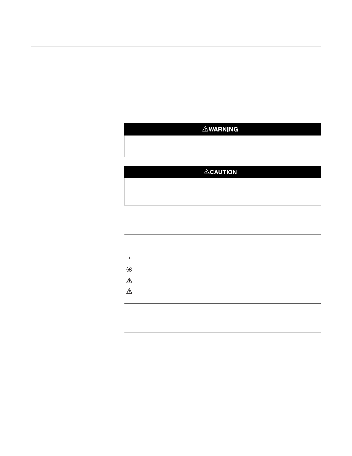
DEFINITIONS The following definitions apply to WARNINGS, CAUTIONS, and NOTES
found throughout this publication.
Highlights an operation or maintenance procedure, practice, condition, statement, etc. If not
strictly observed, could result in injury, death, or long-term health hazards of personnel.
Highlights an operation or maintenance procedure, practice, condition, statement, etc. If not
strictly observed, could result in damage to or destruction of equipment, or loss of
effectiveness.
SYMBOLS
NOTE
Highlights an essential operating procedure, condition, or statement.
: EARTH (GROUND) TERMINAL
: PROTECTIVE CONDUCTOR TERMINAL
: RISK OF ELECTRICAL SHOCK
: WARNING: REFER TO INSTRUCTION BULLETI
NOTE TO USERS
The number in the lower right corner of each illustration in this publication is a
manual illustration number. It is not a part number, and is not related to the
illustration in any technical manner.
ii
Page 5

Instruction Manual
IM-106-5500, Original Issue
August 2005
CCO 5500
Table of Contents
Essential Instructions. . . . . . . . . . . . . . . . . . . . . . . . . . . . . . . . . . . . . . . . i
Preface . . . . . . . . . . . . . . . . . . . . . . . . . . . . . . . . . . . . . . . . . . . . . . . . . ii
Definitions . . . . . . . . . . . . . . . . . . . . . . . . . . . . . . . . . . . . . . . . . . . . . . . ii
Symbols . . . . . . . . . . . . . . . . . . . . . . . . . . . . . . . . . . . . . . . . . . . . . . . . . ii
SECTION 1
Description and
Specifications
SECTION 2
Installation
Overview . . . . . . . . . . . . . . . . . . . . . . . . . . . . . . . . . . . . . . . . . . . . . . . 1-1
System Description . . . . . . . . . . . . . . . . . . . . . . . . . . . . . . . . . . . . . . . 1-1
Infrared Transmitter Unit. . . . . . . . . . . . . . . . . . . . . . . . . . . . . . . . . 1-2
Infrared Receiver Unit. . . . . . . . . . . . . . . . . . . . . . . . . . . . . . . . . . . 1-3
Signal Processor Unit . . . . . . . . . . . . . . . . . . . . . . . . . . . . . . . . . . . 1-4
Power Supply Unit . . . . . . . . . . . . . . . . . . . . . . . . . . . . . . . . . . . . . 1-4
Air Purge. . . . . . . . . . . . . . . . . . . . . . . . . . . . . . . . . . . . . . . . . . . . . 1-4
Isolating Valves . . . . . . . . . . . . . . . . . . . . . . . . . . . . . . . . . . . . . . . 1-4
Principles and Modes of Operation . . . . . . . . . . . . . . . . . . . . . . . . . . . 1-4
Calculation of Gas Concentration. . . . . . . . . . . . . . . . . . . . . . . . . . 1-4
Error Compensation . . . . . . . . . . . . . . . . . . . . . . . . . . . . . . . . . . . . 1-5
Calculation Sequence. . . . . . . . . . . . . . . . . . . . . . . . . . . . . . . . . . . 1-6
Normalization Equations. . . . . . . . . . . . . . . . . . . . . . . . . . . . . . . . . 1-6
Specifications. . . . . . . . . . . . . . . . . . . . . . . . . . . . . . . . . . . . . . . . . . . 1-11
Safety Considerations . . . . . . . . . . . . . . . . . . . . . . . . . . . . . . . . . . . . . 2-2
Electrical Supply Data . . . . . . . . . . . . . . . . . . . . . . . . . . . . . . . . . . . . . 2-2
AC Supplies . . . . . . . . . . . . . . . . . . . . . . . . . . . . . . . . . . . . . . . . . . 2-2
Outputs . . . . . . . . . . . . . . . . . . . . . . . . . . . . . . . . . . . . . . . . . . . . . . 2-2
Normalizing Inputs . . . . . . . . . . . . . . . . . . . . . . . . . . . . . . . . . . . . . 2-2
Plant Status Input . . . . . . . . . . . . . . . . . . . . . . . . . . . . . . . . . . . . . . 2-2
Cable Requirements . . . . . . . . . . . . . . . . . . . . . . . . . . . . . . . . . . . . . . 2-3
Unpacking the Equipment . . . . . . . . . . . . . . . . . . . . . . . . . . . . . . . . . . 2-3
Selecting Location . . . . . . . . . . . . . . . . . . . . . . . . . . . . . . . . . . . . . . . . 2-3
Points to Consider . . . . . . . . . . . . . . . . . . . . . . . . . . . . . . . . . . . . . 2-4
Duct Work . . . . . . . . . . . . . . . . . . . . . . . . . . . . . . . . . . . . . . . . . . . . . . 2-4
Isolating Valves . . . . . . . . . . . . . . . . . . . . . . . . . . . . . . . . . . . . . . . . . . 2-6
Air Purge . . . . . . . . . . . . . . . . . . . . . . . . . . . . . . . . . . . . . . . . . . . . . . . 2-6
Transmitter and Receiver . . . . . . . . . . . . . . . . . . . . . . . . . . . . . . . . . . 2-6
Air Supply . . . . . . . . . . . . . . . . . . . . . . . . . . . . . . . . . . . . . . . . . . . . . . 2-7
Signal Processor Unit . . . . . . . . . . . . . . . . . . . . . . . . . . . . . . . . . . . . . 2-8
Power Supply Unit . . . . . . . . . . . . . . . . . . . . . . . . . . . . . . . . . . . . . . . . 2-9
Electrical Connections . . . . . . . . . . . . . . . . . . . . . . . . . . . . . . . . . . . . . 2-9
Installation of Cables . . . . . . . . . . . . . . . . . . . . . . . . . . . . . . . . . . . 2-9
Cable Connections . . . . . . . . . . . . . . . . . . . . . . . . . . . . . . . . . . . . . 2-9
http://www.raihome.com
Page 6

CCO 5500
Instruction Manual
IM-106-5500, Original Issue
August 2005
SECTION 3
Configuration and
Startup
SECTION 4
Normal Operation
Introduction . . . . . . . . . . . . . . . . . . . . . . . . . . . . . . . . . . . . . . . . . . . . . 3-1
Safety Considerations . . . . . . . . . . . . . . . . . . . . . . . . . . . . . . . . . . . . . 3-1
Power Supply Voltage Selection . . . . . . . . . . . . . . . . . . . . . . . . . . . . . 3-2
Turning the Power On . . . . . . . . . . . . . . . . . . . . . . . . . . . . . . . . . . . . . 3-2
Alignment. . . . . . . . . . . . . . . . . . . . . . . . . . . . . . . . . . . . . . . . . . . . . . . 3-2
Detector Levels . . . . . . . . . . . . . . . . . . . . . . . . . . . . . . . . . . . . . . . . . . 3-4
Receiver Gain Adjustment . . . . . . . . . . . . . . . . . . . . . . . . . . . . . . . 3-4
Signal Processor Gain Adjustment. . . . . . . . . . . . . . . . . . . . . . . . . 3-6
Transmitter Adjustments . . . . . . . . . . . . . . . . . . . . . . . . . . . . . . . . . . . 3-7
Source Intensity . . . . . . . . . . . . . . . . . . . . . . . . . . . . . . . . . . . . . . . 3-7
Chopper Frequency . . . . . . . . . . . . . . . . . . . . . . . . . . . . . . . . . . . . 3-7
Operating Parameters . . . . . . . . . . . . . . . . . . . . . . . . . . . . . . . . . . . . . 3-7
Current Output Calibration. . . . . . . . . . . . . . . . . . . . . . . . . . . . . . . . . 3-19
Introduction . . . . . . . . . . . . . . . . . . . . . . . . . . . . . . . . . . . . . . . . . . . . . 4-1
Measurement . . . . . . . . . . . . . . . . . . . . . . . . . . . . . . . . . . . . . . . . . 4-1
Calibration . . . . . . . . . . . . . . . . . . . . . . . . . . . . . . . . . . . . . . . . . . . 4-1
Normal Startup Procedure . . . . . . . . . . . . . . . . . . . . . . . . . . . . . . . . . . 4-1
Modes of Operation . . . . . . . . . . . . . . . . . . . . . . . . . . . . . . . . . . . . . . . 4-2
Key Operation . . . . . . . . . . . . . . . . . . . . . . . . . . . . . . . . . . . . . . . . . . . 4-3
Program Tree. . . . . . . . . . . . . . . . . . . . . . . . . . . . . . . . . . . . . . . . . . . . 4-3
Operating Mode . . . . . . . . . . . . . . . . . . . . . . . . . . . . . . . . . . . . . . . . . . 4-5
Parameter Mode . . . . . . . . . . . . . . . . . . . . . . . . . . . . . . . . . . . . . . . . . 4-5
Identification . . . . . . . . . . . . . . . . . . . . . . . . . . . . . . . . . . . . . . . . . . 4-5
Parameters . . . . . . . . . . . . . . . . . . . . . . . . . . . . . . . . . . . . . . . . . . . 4-5
Averages . . . . . . . . . . . . . . . . . . . . . . . . . . . . . . . . . . . . . . . . . . . . 4-5
Output. . . . . . . . . . . . . . . . . . . . . . . . . . . . . . . . . . . . . . . . . . . . . . . 4-5
Alarm . . . . . . . . . . . . . . . . . . . . . . . . . . . . . . . . . . . . . . . . . . . . . . . 4-6
Plant Status . . . . . . . . . . . . . . . . . . . . . . . . . . . . . . . . . . . . . . . . . . 4-6
Normalization. . . . . . . . . . . . . . . . . . . . . . . . . . . . . . . . . . . . . . . . . . . . 4-6
Display Format . . . . . . . . . . . . . . . . . . . . . . . . . . . . . . . . . . . . . . . . 4-6
Diagnostic Mode . . . . . . . . . . . . . . . . . . . . . . . . . . . . . . . . . . . . . . . . . 4-6
Detector Levels. . . . . . . . . . . . . . . . . . . . . . . . . . . . . . . . . . . . . . . . 4-7
Chopper Motor Frequency . . . . . . . . . . . . . . . . . . . . . . . . . . . . . . . 4-8
YVals and Gas ppm . . . . . . . . . . . . . . . . . . . . . . . . . . . . . . . . . . . . 4-8
Calibration Data . . . . . . . . . . . . . . . . . . . . . . . . . . . . . . . . . . . . . . . 4-8
Fault Condition . . . . . . . . . . . . . . . . . . . . . . . . . . . . . . . . . . . . . . . . 4-9
Setup Mode . . . . . . . . . . . . . . . . . . . . . . . . . . . . . . . . . . . . . . . . . 4-10
Security Code Entry . . . . . . . . . . . . . . . . . . . . . . . . . . . . . . . . . . . 4-10
Set Averages . . . . . . . . . . . . . . . . . . . . . . . . . . . . . . . . . . . . . . . . 4-11
Configure O/P. . . . . . . . . . . . . . . . . . . . . . . . . . . . . . . . . . . . . . . . 4-12
Parameters . . . . . . . . . . . . . . . . . . . . . . . . . . . . . . . . . . . . . . . . . . 4-14
Normalization . . . . . . . . . . . . . . . . . . . . . . . . . . . . . . . . . . . . . . . . 4-17
Setting the Normalizing Parameters. . . . . . . . . . . . . . . . . . . . . . . 4-18
Temperature . . . . . . . . . . . . . . . . . . . . . . . . . . . . . . . . . . . . . . . . . 4-18
Oxygen . . . . . . . . . . . . . . . . . . . . . . . . . . . . . . . . . . . . . . . . . . . . . 4-19
Pressure . . . . . . . . . . . . . . . . . . . . . . . . . . . . . . . . . . . . . . . . . . . . 4-19
Water Vapor . . . . . . . . . . . . . . . . . . . . . . . . . . . . . . . . . . . . . . . . . 4-19
Reset Averages . . . . . . . . . . . . . . . . . . . . . . . . . . . . . . . . . . . . . . 4-19
Calibrate . . . . . . . . . . . . . . . . . . . . . . . . . . . . . . . . . . . . . . . . . . . . 4-20
Check Cell Mode . . . . . . . . . . . . . . . . . . . . . . . . . . . . . . . . . . . . . . . . 4-20
Normal Shutdown Procedure. . . . . . . . . . . . . . . . . . . . . . . . . . . . . . . 4-21
TOC-2
Page 7

Instruction Manual
IM-106-5500, Original Issue
August 2005
CCO 5500
Routine Checks . . . . . . . . . . . . . . . . . . . . . . . . . . . . . . . . . . . . . . . . . 4-21
Notes for Using a Rosemount Analytical Check Cell . . . . . . . . . . 4-21
Alarms and Emergency Conditions . . . . . . . . . . . . . . . . . . . . . . . 4-23
Emergency Shutdown Procedure. . . . . . . . . . . . . . . . . . . . . . . . . 4-23
Isolation Procedure. . . . . . . . . . . . . . . . . . . . . . . . . . . . . . . . . . . . 4-23
Interface with Integrated Emissions Monitoring System . . . . . . . . 4-23
SECTION 5
Maintenance
SECTION 6
Troubleshooting
SECTION 7
Returning Material
SECTION 8
Replacement Parts
Routine (Preventive) Maintenance . . . . . . . . . . . . . . . . . . . . . . . . . . . 5-1
Cleaning Windows . . . . . . . . . . . . . . . . . . . . . . . . . . . . . . . . . . . . . 5-1
Replacement of the Heater Element . . . . . . . . . . . . . . . . . . . . . . . 5-1
Replacement of Chopper Motor Assembly. . . . . . . . . . . . . . . . . . . 5-2
Replacement of Gas Cells . . . . . . . . . . . . . . . . . . . . . . . . . . . . . . . 5-2
Electronics . . . . . . . . . . . . . . . . . . . . . . . . . . . . . . . . . . . . . . . . . . . 5-3
Span Factor Adjustment . . . . . . . . . . . . . . . . . . . . . . . . . . . . . . . . . . . 5-3
Fault Finding with the Keypad . . . . . . . . . . . . . . . . . . . . . . . . . . . . . . . 6-1
Data Valid LED Out . . . . . . . . . . . . . . . . . . . . . . . . . . . . . . . . . . . . 6-1
Troubleshooting Tables . . . . . . . . . . . . . . . . . . . . . . . . . . . . . . . . . . . . 6-2
Component Tests . . . . . . . . . . . . . . . . . . . . . . . . . . . . . . . . . . . . . . . . 6-8
Heater Cartridge . . . . . . . . . . . . . . . . . . . . . . . . . . . . . . . . . . . . . . . 6-8
Chopper Motor . . . . . . . . . . . . . . . . . . . . . . . . . . . . . . . . . . . . . . . . 6-8
LED Indications . . . . . . . . . . . . . . . . . . . . . . . . . . . . . . . . . . . . . . . . . . 6-8
Test Points. . . . . . . . . . . . . . . . . . . . . . . . . . . . . . . . . . . . . . . . . . . . . . 6-9
Recommended Spare Parts . . . . . . . . . . . . . . . . . . . . . . . . . . . . . . . . 8-1
Parts List . . . . . . . . . . . . . . . . . . . . . . . . . . . . . . . . . . . . . . . . . . . . . . . 8-1
APPENDIX A
Safety Data
Safety Instructions . . . . . . . . . . . . . . . . . . . . . . . . . . . . . . . . . . . . . . . . A-2
TOC-3
Page 8

CCO 5500
Instruction Manual
IM-106-5500, Original Issue
August 2005
TOC-4
Page 9

Instruction Manual
IM-106-5500, Original Issue
August 2005
CCO 5500
Section 1 Description and Specifications
Overview . . . . . . . . . . . . . . . . . . . . . . . . . . . . . . . . . . . . . . . page 1-1
System Description . . . . . . . . . . . . . . . . . . . . . . . . . . . . . . page 1-1
Principles and Modes of Operation . . . . . . . . . . . . . . . . . page 1-4
Specifications . . . . . . . . . . . . . . . . . . . . . . . . . . . . . . . . . . . page 1-11
OVERVIEW Rapid advances in the design of 'across the duct' infrared gas analyzers have
led to the general acceptance of this technique for the monitoring of gas levels
in flue gases of power generation boilers and large industrial process steam
boilers.
The CCO 5500 is designed to operate on duct widths of less than 26 ft (8 m)
at flue gas temperatures up to 572
makes installation extremely simple, and through the use of microprocessor
technology they have many advanced features:
• Local normalizing inputs for compliance with legislation requirements
• Serial data facility to allow communication between analyzers and a
central data logging station
• User-definable output in either mg/m
• Four rolling averages are held - selectable from 10 seconds to 30 days
• Integral, back lit 32 character LCD provides diagnostic and
measurement information
• Plant status input to prevent emissions dilution during plant off periods
o
F (300oC). Their rugged construction
3
, mg/Nm3 or ppm
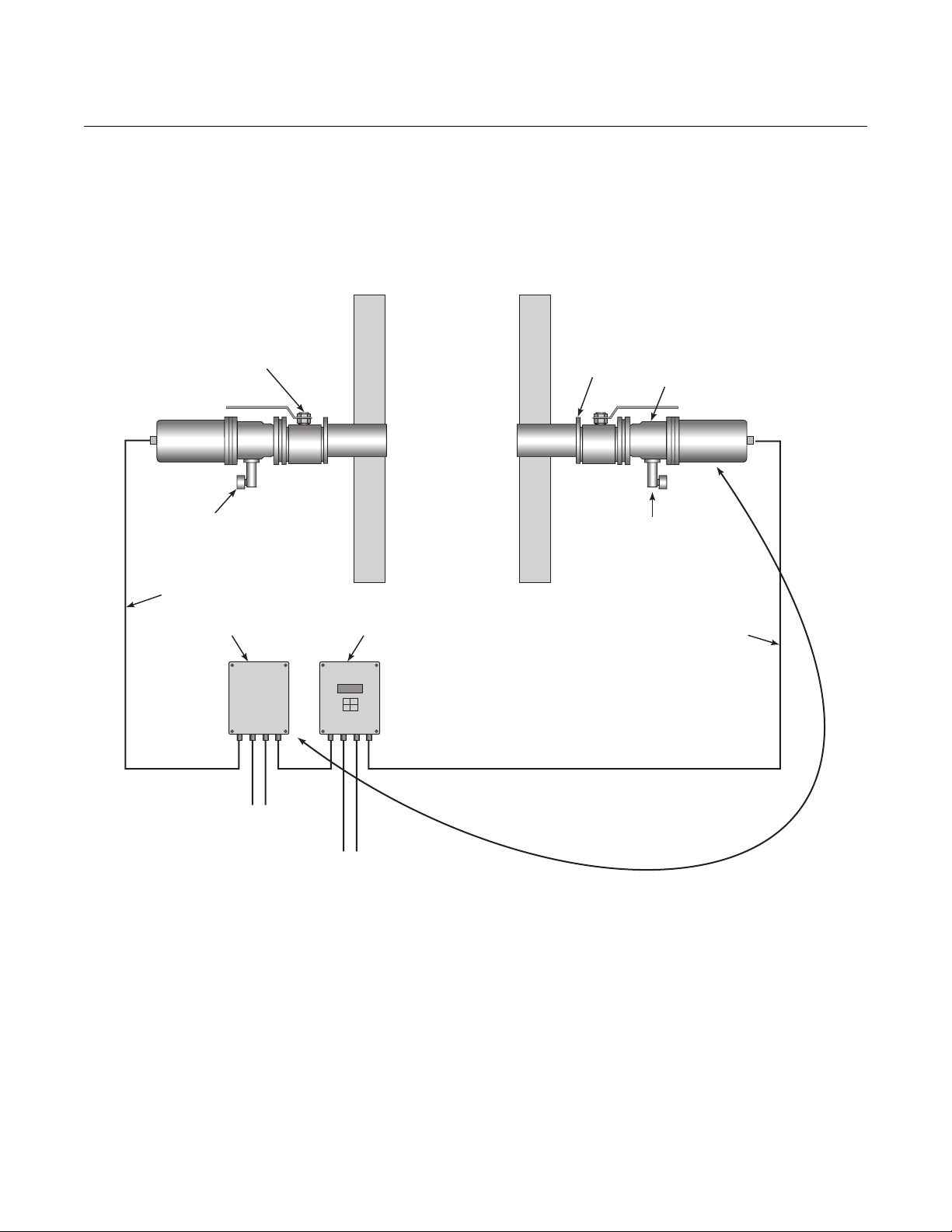
SYSTEM DESCRIPTION The CCO 5500 Carbon Monoxide (CO) Analyzer Monitor consists of four
items (Figure 1-1):
• An infrared transmitter unit to project a beam of infrared radiation
across the duct
•A receiver to measure that radiation
•A power supply unit to provide the necessary power rails, and
•A signal processor to compute the gas concentration from the signals
provided by the receiver unit.
http://www.raihome.com
Page 10
CCO 5500
SerialDataPo
Figure 1-1. Typical System Layout
Instruction Manual
IM-106-5500, Original Issue
August 2005
Each of these units is designed to be rugged and durable. They are all fully
sealed to IP65 standards and are suitable for outside mounting, without the
need for further weatherproof enclosures.
Transmitter
Isolation Valve
(If Used)
Pressure
Regulator
33 ft(10 m) Max.
Power Supply
Signal Processor
Site Mounting
Flange
Receiver
Air Purge
Purge Air
33 ft(10 m) Standard
Mains Supply &
Contact Outputs
Analogue Outputs,
Normalizing Inputs &
rt
82 ft(25 m) Maximum Total Cable Length
Between Receiver & Power Supply
Infrared Transmitter Unit At the heart of this unit is a small heater assembly designed to give a high
intensity uniform source of infrared energy over a long lifetime, in excess of
two years continuous operation, with a power consumption of only 26 watts.
The heater has a stainless steel cylindrical core, plasma coated with
refractory, and around which is a 'Kanthal' heating element. This is then
enclosed within refractory fibers and encapsulated in an aluminium cartridge.
In the infrequent event of failure, the complete heater assembly can be
replaced on site within ten minutes.
1-2
Page 11
Instruction Manual
IM-106-5500, Original Issue
August 2005
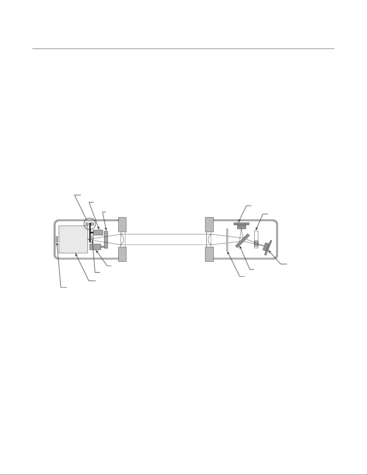
Figure 1-2. Transmitter and Receiver Schematic
Chopper Blade Detector
Chopper Blade & Motor
The radiation emitted by the heater is then 'chopped' by a motor-driven disc,
and focused across the duct by a lens. The chopper disc is driven by a small
DC motor. The phase and frequency of the chopper disc are monitored by a
radiation detector to provide a reference signal that is utilized by the signal
processor unit.
System calibration is achieved by a small calibration cell containing pure
reference gas (CO) that can be swung into the sight path by means of a
'stepper' motor and gearbox assembly to enable continuous calibration
updates to be maintained. The chopper motor and stepper motor represent
the only moving components in the entire system.
A printed circuit board mounted at the front of the unit provides control
circuitry for the heater, the motors, and the reference wave detector.
Figure 1-2 illustrates the transmitter and receiver units.
Calibrating Cell
CCO 5500
Detector D2
Gas Filter
Detector D1
Heated Infrared Source
Control Detector
Stepper Motor & Gearbox
Reference Detector
Beam Splitter
Interference Filter
Infrared Receiver Unit The precision and reliability which CO concentration levels can be measured
governs the performance of the complete instrument. For this reason design
efforts have been concentrated in producing an extremely simple and robust
receiver unit. It contains no moving parts, is fully sealed and designed to give
many years of trouble-free and maintenance-free operation.
The unit comprises a lens to focus radiation received from across the duct,
followed by a precision interference filter to limit the wave band of energy
used. This filter tolerance is strictly controlled since it alone determines the
instrument scale shape and calibration. The radiation then passes to an
optical beam-splitter where approximately half the radiation is reflected at
right angles directly onto a radiation detector. The other half of the radiation is
transmitted, by the beam-splitter, through a gas cell containing pure reference
gas (CO) and onto a second radiation detector.
The detectors used are lithium tantalate pyro-electric detectors, renowned for
their sensitivity, stability and ability to operate at normal ambient
temperatures, without the need for cooling. They respond only to changing
levels of radiation and thus to the chopped radiation from the infrared source
unit and not to background radiation from the flue or flue gas. The detector
signals are amplified and fed to the signal processor unit.
1-3
Page 12

Instruction Manual
IM-106-5500, Original Issue
CCO 5500
August 2005
Signal Processor Unit The signal processor unit is housed in a fully-sealed cast-aluminum
enclosure. It houses the microprocessor to monitor the data from the receiver
and produces a 4-20 mA output signal for gas levels within the flue.
A non-volatile RAM section - requiring no battery back-up - enables all of its
operation data to be retained during a power down condition. The instrument
can resume operation immediately when power is restored without having to
be recalibrated.
All operation data is entered via a surface-mounted keypad. A 32-character
LCD provides the operator with measurement details and diagnostic
information.
Inputs are available to receive the 4-20 mA outputs of normalizing
measurement transducers - O
data can also be entered via the keypad or via the serial data port.
A serial communication facility within the processor allows the instrument to
communicate with other Rosemount analyzers and a central data logging unit.
, temperature and pressure, if required. This
2
Power Supply Unit The power supply unit is housed in a fully-sealed cast-aluminium enclosure
and contains the power supplies for the instrument. A switched mode power
supply is utilized to provide an extremely stable power source, able to cope
with large fluctuations in the supply voltage. The contact outputs are also
taken from this unit - data valid and high gas alarm.
Air Purge The air purge unit has its own integral adjustable mount and provides the
interface between the site mounting flange and the transmitter and receiver
units. The purge is designed to provide a steady laminar flow of air away from
the instrument lens, preventing optical contamination.
A supply of air to the purge is essential.
Isolating Valves Isolating valves, if required, may be attached between the air purges and the
duct. These will allow protection for personnel servicing instruments on high
pressure ducts.
PRINCIPLES AND MODES OF OPERATION
Calculation of Gas Concentration
Gas levels are determined by measuring the absorption of infrared radiation,
transmitted through the flue gas, in a wave band sensitive to absorption by the
measurement gas. CCO 5500 monitors have two detectors; one measures
the radiation directly to provide a live output, sensitive to the measurement
gas, while a second detector measures the radiation after passing through a
gas cell filled with pure reference gas (CO), to provide a reference
measurement, completely unaffected by the measurement gas.
1-4
Page 13

Instruction Manual
IM-106-5500, Original Issue
August 2005
The basic expression from which the gas concentration in the gas is
determined is:
Y = G - K. D2/D1
Where D1 = the reference output from the detector
D2 = the live output from the detector
G = a scaling factor (1600)
K = a constant, known as the zero correction
factor, set so that when there is zero
measurement gas in the duct, Y = 0
thus, K = G. D1(0)
D2 (0)
This parameter Y is then smoothed, linearized and compensated for effects of
path length and flue gas temperature, to produce a measurement of gas
concentration in the flue gas.
CCO 5500
Error Compensation The accurate determination of gas concentration depends on the
measurement of the radiation levels received by the detectors. Any error in
that measurement caused by detector drift will produce errors in the
determination of the gas level. In order to maintain accuracy, it is necessary to
be able to compensate for such drifts. In the CCO 5500 analyzer a technique
of continuous calibration adjustment is used.
The operating cycle of the instrument is in two parts. First, measurements are
obtained from the two detector outputs D1 and D2. The calibration cell,
containing pure CO, is then positioned in the sight path and the two detector
outputs are measured again to give readings E1 and E2.
From the basic scale shape equation:
Y = G - K. D2/D1
and from the calibration equation
Yo = G - K. E2/E1
or K = (G - Yo). E1/E2
thus substituting in the scale shape equation
Y = G - (G - Yo). E1/E2. D2/D1
The two ratios E1/D1 and E2/D2, being derived each from one detector, are
independent of any detector drift, thus making the instrument output
independent of any drift or change in detector gain characteristic.
This operating routine, giving measurements first of D1 and D2 and then, with
the calibration cell in position, of E1 and E2, is repeated continuously and
provides an effective continuous calibration update to enable accuracy to be
maintained at all times.
1-5
Page 14

Instruction Manual
IM-106-5500, Original Issue
CCO 5500
August 2005
Calculation Sequence The calculations for one complete operating cycle of the instrument are given
below:
•measure D1 & D2
• measure E1 & E2
• compute Y
• smooth Y
• linearize and correct for path length
• normalize measurement
• smooth to produce final gas outputs
Normalization Equations Normalization of data collected by the analyses is essential to compare
emission levels of pollutants into the atmosphere. Software in Rosemount
Analyzers perform all calculations and provides results in various units, vpm,
3
mg/m
and mg/Nm3; derivation of these results is described in this section.
CCO 5500 CO analyzers are cross-duct type and thus measure the quantity
(or number of molecules) of gas within their sight path. This measurement is
converted into a concentration which is fully compensated for the expansion
effects of temperature, while assuming constant atmospheric pressure. This
basic measurement is referred to as 'ppm' (parts per million). However, to
obtain a true concentration 'vpm' (ppm by volume) the 'ppm' value must be
normalized for pressure using the following expression.
Correction to standard pressure -
vpm = ppm x standard pressure (abs)
measured pressure (abs)
where standard pressure is taken as 101 kPascals.
The next stage in the process is to determine the mass concentration. The
conversion at STP uses conversion factors determined as follows:
Conversion to mass concentration -
N=RMM
V
where N = conversion factor
RMM = relative molecular mass of the gas
V = 22.4 (standard volume of an ideal gas)
The conversion factor given below:
Conversion factors (N) -
Molecular mass (RMM) = 12 + 16 = 28
1 vpm = 28/22.4 = 1.25 mg/m
The mass concentration present is calculated as below:
3
mg/m
(STP) = N. vpm
3
1-6
This value is the mass concentration of the gas at STP.
Correction for oxygen and water vapor.
Finally the effects of water vapor and oxygen need to be considered.
Page 15

Instruction Manual
IM-106-5500, Original Issue
August 2005
CCO 5500
Since the vpm measurement is already normalized for temperature and
pressure, the only further normalization required is for the dilution effects of
water vapor and oxygen. These are straightforward calculations as shown
below:
mg/Nm
3
= mg/m3 (STP) x 20.9 - 0%2 standard x100
20.9 - (0%2 measured) DRY = 100 - H2O%
20.9% is taken as the level of free oxygen in dry air.
NOTE
If the measured O
% is a wet measurement the measured O2 concentration
2
must be corrected to a dry measurement. This is performed automatically by
the software if the measured O
concentration is defined as a wet
2
measurement; where:
(O
% measured) DRY = (O2% measured) WET x 100
2
100 - H2O%
If no correction is required for oxygen then standard O
If no correction is required for water vapor then H
= O2 measured.
2
O% = 0
2
After all these calculations have been performed the resulting measurement
is the effective mass concentration of the pollutant normalized to standard
conditions (in mg/Nm
3
).
Measured conditions -
Where measured values are required (e.g. to calculate rates of emissions)
they need to be recalculated for measured temperature and pressure as
shown below:
3
mg/m
= N.vpm x 273 x measured pressure
T standard pressure
substituting,
vpm = ppm x standard pressure
measured pressure
the measured mass concentration of the gas is:
3
= N.ppm x 273
mg/m
T
Principles of Cross-Duct Gas Analyzers
Cross-duct analyzers work on the basic principle that infrared (IR) energy is
absorbed by particular gases in a manner very specific to the gas.
Although cross-duct analysis will differ from gas to gas, the basic principles
are similar for all measured gases. This section examines the analysis of
carbon monoxide in detail.
1-7
Page 16
CCO 5500
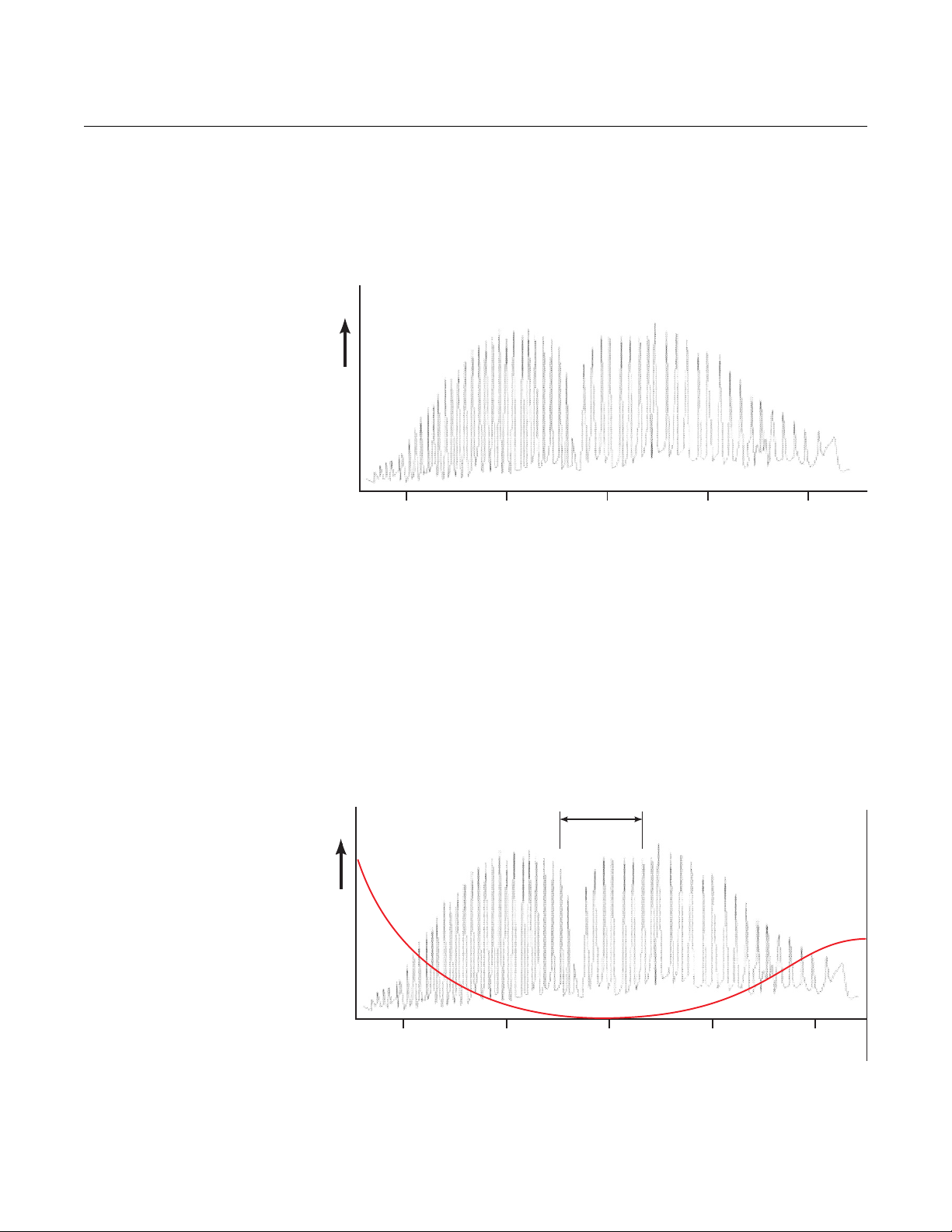
Figure 1-3. CO IR Absorption Spectrum
Instruction Manual
IM-106-5500, Original Issue
August 2005
Carbon Monoxide IR Absorption Spectrum
Carbon monoxide absorbs IR energy in a band between wavelengths of
approximately 4.5 and 4.9 µm. The absorption spectrum is complex and is
illustrated in Figure 1-3 below.
Absorption (%)
0
4.5 4.6 4.7 4.8 4.9
Wavelength (microns)
Figure 1-4. Comparison of Spectra
However, two other common flue gas constituents - carbon dioxide and water
vapor - also absorb energy within this wave band. Fortunately, at 4.7µm, IR
absorption by each of these gases is at a minimum. Figure 1-4 demonstrates
how the absorption spectra of CO, CO
and water vapor affect wavelengths of
2
between 4.5 and 4.9 µm.
Absorption Spectra of CO, CO
and Water Vapor
2
By using a narrow band pass filter which only passes IR energy at
wavelengths of around 4.7µm, correctly designed CO analyzers are able to
ignore the effects of water vapor and CO
. (The filter characteristics are
2
shown in Figure 1-4). No other flue gases absorb IR energy in this band.
Filter
Limits
CO
2
HO
2
Absorption (%)
1-8
0
4.5 4.6 4.7 4.8 4.9
Wavelength (microns)
Page 17
Instruction Manual
IM-106-5500, Original Issue
August 2005
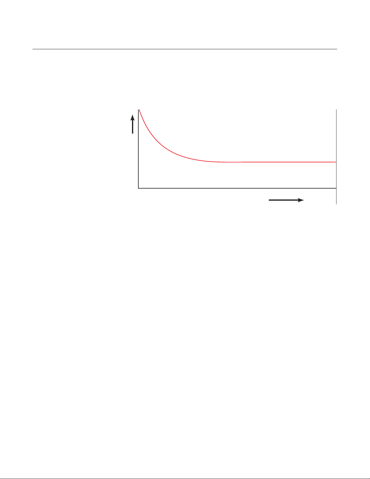
Figure 1-5. Transmissivity of CO
CCO 5500
Transmissivity of CO Within the 4.7µm Band
The transmission through the gas of the IR energy at about 4.7µm is affected
by the concentration of CO. Figure 1-5 illustrates how the energy within the
selected band varies with CO concentration.
Transmission (%)
0
CO Concentration (ppm.m)
The shape of this curve is fixed by the characteristics of the 4.7µm filter - it
cannot change, and the curve is practically flat at CO concentrations of above
10,000 ppm.meters. A cross-duct monitor effectively measures CO molecules
in its optical path, so the same concentration of CO will have a greater effect
across a large measurement path than a small measurement path. The term
ppm.meters is the concentration of CO within the duct multiplied by the gas
path length over which it has been measured.
Carbon Monoxide Calculation
CCO 5500 Analyzers make two measurements of IR energy in the narrow
band around 4.7µm. Both measurements are made after the beam has
passed through the gas to be measured. One, however, also passes through
a cell containing pure CO (the gas cell shown in Figure 1-2). This absorbs all
the energy capable of being absorbed by CO and provides a reference that is
unaffected by any CO in the duct, but will be affected by any other material
(e.g. dust) which reduces the energy received from the transmitter, in exactly
the same way as the other beam.
The second beam does not have such a cell in front of it and, as such, is very
sensitive to changes in CO within the duct.
The measurement of CO is calculated from a parameter Y, where:
Y=G-K.D2/D1
and D2 = the live detector output
D1 = the reference detector output
K = a composite gain factor which takes
account of all optical and electronic gains
G = scaling factor
1-9
Page 18
CCO 5500
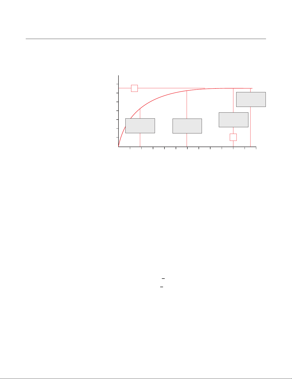
Figure 1-6. Calibration Curve
Instruction Manual
IM-106-5500, Original Issue
August 2005
Calibration
Figure 1-6 shows the parameter Y against the CO concentration.
0.14
0.12
0.10
0.08
Parameter Y
0.06
0.04
0.02
0
A
CO
In Duct
12
4
567891011123
CO ppm.m (x1000)
Practical
Limit
Calibration
Point
B
Calibration Point
Including
CO in Duct
This is the calibration curve for the instrument and is opposite in shape to the
transmissivity curve shown in Figure 1-5. Each is fixed by the characteristics
of the 4.7µm filter and cannot change. Rosemount Analytical analyzers make
full use of this scale shape to provide an easily attainable calibration point.
It is not necessary to calculate K because we know that when the constant K
is correct:
Y is 0 when the CO level is 0
If there is any drift in the measurement, it can only be due to a change in
some optical or electronic gain and can always be corrected by setting Y to
zero when the CO level is zero.
1-10
In practice, however, it is not always possible to produce a zero CO level, but
if we consider the calibration curve, we can see that:
if Y = 0 when CO = 0
then Y = a when CO = b
We can also see from Figure 1-6 that at high CO levels, the parameter Y
becomes completely insensitive to variable CO levels in the duct, such that:
Y = a when the CO >
By making Y = a when CO >
b
b, Y = 0 when CO = 0 and all these errors are
eliminated.
A gas cell containing pure carbon monoxide can be introduced into the IR
beam at the source. This cell represents a value of 10,000 ppm.meters and
provides a reference point for the calibration of the instrument. Any further CO
in the duct will have negligible effect on the reference point because the
calibration curve is flat at these high concentrations of CO. Well-designed
cross-duct analyzers introduce this gas cell regularly - every few seconds - to
continuously check and (if necessary) modify their zero position.
Page 19

Instruction Manual
IM-106-5500, Original Issue
August 2005
SPECIFICATIONS
CCO 5500
CCO 5500 Specifications
Span* Selectable from 0-100 ppm to 0-10,000 ppm,
within the range 200 to 6,000 ppm.meters at
STP
Display Units ppm
Averaging Four averages selectable from
Accuracy ±2% of measurements or
Outputs
Analog
High Alarm
Data Valid
Inputs
Oxygen
Temperature
Pressure
Plant Status Contact
Serial Port For remote instrument operation,
Path Length 1.6 to 26 ft (0.5 to 8 m)
Flue Gas Temperature 1202oF (0 to 650oC)
Construction Cast aluminium, fully sealed to IP65
Transmitter Electrically heated silicon nitride cylinder
Detector Lithium tantalate pyro-electric detector
Ambient Temperature Limits -4oF to 158oF (-20oC to 70oC)
Power Requirements 85-132/170-264V AC, 50/60 Hz, 50VA
Air Purge Consumption 2.2 cfm @ 14.9 psi (1 liter/sec @ 1 bar)
3
mg/m
(measured)
3
mg/Nm
(normalized)
10 seconds to 30 days
±5 ppm whichever is greater
4-20 mA isolated, 500S max.
Volt-free contact, 10A @ 250V
Volt-free contact, 10A @ 250V
4-20 mA
4-20 mA
4-20 mA
Volt-free Contact
normalizing inputs and outputs
(compressed air)
11 cfm (5 liter/sec) (blower air)
NOTE:
*The range of the output span is quoted in ppm.meters. To obtain the
minimum and maximum span for your application, divide these figures by the
path length in meters.
1-11
Page 20

CCO 5500
Instruction Manual
IM-106-5500, Original Issue
August 2005
1-12
Page 21
Instruction Manual
IM-106-5500, Original Issue
August 2005
Section 2 Installation
Safety Considerations . . . . . . . . . . . . . . . . . . . . . . . . . . . . page 2-2
Electrical Supply Data . . . . . . . . . . . . . . . . . . . . . . . . . . . . page 2-2
Unpacking the Equipment . . . . . . . . . . . . . . . . . . . . . . . . . page 2-3
Selecting Location . . . . . . . . . . . . . . . . . . . . . . . . . . . . . . . page 2-3
Duct Work . . . . . . . . . . . . . . . . . . . . . . . . . . . . . . . . . . . . . . page 2-4
Isolating Valves . . . . . . . . . . . . . . . . . . . . . . . . . . . . . . . . . . page 2-6
Air Purge . . . . . . . . . . . . . . . . . . . . . . . . . . . . . . . . . . . . . . . page 2-6
Transmitter and Receiver . . . . . . . . . . . . . . . . . . . . . . . . . . page 2-6
Air Supply . . . . . . . . . . . . . . . . . . . . . . . . . . . . . . . . . . . . . . page 2-7
Signal Processor Unit . . . . . . . . . . . . . . . . . . . . . . . . . . . . page 2-8
Power Supply Unit . . . . . . . . . . . . . . . . . . . . . . . . . . . . . . . page 2-9
Electrical Connections . . . . . . . . . . . . . . . . . . . . . . . . . . . . page 2-9
CCO 5500
Before installing this equipment, read the “Safety instructions for the wiring and installation
of this apparatus” in Appendix A. Failure to follow safety instructions could result in serious
injury or death.
Install all protective equipment covers and safety ground leads after installation. Failure to
install covers and ground leads could result in serious injury or death.
Before making any electrical connections, make sure the AC power supply is first switched
off. Failure to do so could cause personal injury or even death. Make sure that the voltage
and frequency of the AC supply match the designations on the analyzer component tags.
http://www.raihome.com
Page 22

CCO 5500
Instruction Manual
IM-106-5500, Original Issue
August 2005
SAFETY CONSIDERATIONS
The mains power is supplied to the whole system via the power supply.
During installation, DO NOT connect the system to the mains until all units are
in place and fully wired up. Keep the isolating valves, if used, CLOSED. The
compressed air (to be supplied to the air purges) must be turned OFF until the
full installation is complete. If any servicing or rewiring is to be performed
ensure that the power supply is isolated. For configuration the system needs
to have power, compressed air and the isolating valves open.
ELECTRICAL SUPPLY DATA
AC Supplies
The CCO 5500 may be powered from either 85-132V AC/170-264V AC at
47-440 Hz. A switch within the power supply unit selects the input voltage and
an internal 2A/20 mm fuse protects the instrument.
Voltage fluctuations within the above ranges are tolerated without loss of
performance and the total power requirement is less than 50VA.
Outputs Three forms of output are provided:
1. A selectable, fully isolated, current output (either 4-20 mA or 0-20 mA),
maximum load 500S - taken from the signal processor.
2. Single pole change-over relays (rating 250V at 10A), for:
• Alarm triggering at a selectable gas threshold
• Data valid indication, operating under power failure and any
equipment fault condition - see the basic fault finding section for
further details - contact outputs are taken from the power supply unit
3. 4-wire serial data link for 2-way communication with a central processor
- taken from the signal processor unit.
Normalizing Inputs Pressure, temperature, and oxygen values can be held to normalize the
calculated gas value to standard conditions. These values may be read by the
instrument using the following methods:
1. Fixed value from the key pad.
2. 4-20 mA outputs from measurement transducers - the ranges represented by these inputs are set from within the processor - inputs are taken to the signal processor.
3. If the analyzer is part of an integrated system, the serial data line can carry the normalizing values.
Plant Status Input The plant status input facility is available to prevent the rolling average stacks
being diluted by measurements made during periods where the plant is shut
down. It is governed by one of three choices; a serial input (from an integrated
system), the logic input (terminals PS1 and PS2 in the signal processor) and
multiple. Multiple has five options; temperature, oxygen, water vapor
thresholds, and logic input. It is set in Mode 5. All these are described in more
detail later in this manual.
In normal operation (plant operating), the plant status will register as ON.
However, if the plant status condition is broken, the status will change to OFF
and the averaging stacks (minutes, hours, days) will not be updated.
2-2
Page 23

Instruction Manual
IM-106-5500, Original Issue
August 2005
CCO 5500
NOTE
For normal operation terminals PS1 and PS2 must not be linked together.
CABLE REQUIREMENTS 1. Power supply to signal processor - 7-core, shielded, multi-stranded,
2
.
UNPACKING THE EQUIPMENT
6/0.2 mm. 0.5 mm
NOTE
Although screened cable is specified for the interconnecting cable, it is not
necessary for the cable to be grounded.
2. Current loop output - any suitable 2-conductor cable - maximum length depends on keeping output load within the 500S maximum load requirement.
3. Contact outputs - any 2-conductor cable capable of supplying the power to the warning device/relay etc. 250V, 10A maximum.
4. A.C. power - any suitable 3-conductor power cable capable of transmitting 50VA.
5. Serial data link (if required) - twin twisted pair shielded cable - see IEM Communications Manual for further details (Doc. ID 0006/6).
6. Analog inputs - any suitable 2-conductor cable - Rosemount instruments have an internal impedance of 240S for these inputs.
A typical Rosemount Analytical CCO 5500 Carbon Monoxide (CO) Analyzer
should contain the following items. Record the part number, serial number,
and order number for each component of your system.
1. Transmitter with 33 ft (10 m) of cable and air purge.
2. Receiver with 33 ft (10 m) of cable and air purge.
3. Signal processor.
4. Power supply.
5. Site mounting flange (2).
6. Gaskets (4), selected screws and washers.
SELECTING LOCATION The equipment is designed for mounting on boiler ducting or stacks in
positions open to the weather. It is fully sealed and requires no further
enclosures or protection. The specific location of the instrument will depend
on the application and user requirements, but the following considerations
should be made when choosing a site.
2-3
Page 24

CCO 5500
1. The site must be accessible at both sides of the duct for servicing the
transmitter and receiver.
2. The site should be as free from extremes of temperature and vibration
as possible - permissible ambient temperature range -4
o
(-20
C to +70oC).
3. Flue gas temperatures should not exceed 572
measurement - at higher temperatures instrument accuracy will
deteriorate.
4. There must be an uninterrupted sight path available between the transmitter and the receiver.
5. The maximum cable length allowed between the power supply and the transmitter is 33 ft (10 m).
6. The maximum total cable length between the power supply and the receiver is 82 ft (25 m).
See Figure 1-1 for an illustration of a typical system arrangement.
Points to Consider Path Length
• Too long [>26 ft (8 m)] - low energy available.
• Too short [<1.6 ft (0.5 m)] - optical problems.
Instruction Manual
IM-106-5500, Original Issue
August 2005
o
F to 158oF
o
F (300oC) at the point of
Flue Gas Temperature
• Too low (<dewpoint) - potential water droplets.
• Too high [>662
o
F (>300oC)] - reduced sensitivity.
Ambient Temperature
• Too low [< -4
• Too high [>158
o
F (< -20oC)] - condensation on lenses.
o
F (+70oC)] - potential instrument problems.
Measurement Range
• Minimum range depends on acceptable measurement uncertainty,
which is 10 ppm.meters, e.g. for the level of uncertainty to be below 2%
of range, the minimum range would be 500 ppm. meters.
Note: 10 ppm CO = 12.5 mg/m
3
• For increased sensitivity (reduced uncertainty of measurement) the
path length must be maximized.
• Maximum ranges - 6000 ppm.meters.
Note: To correct ppm.meters to effective ppm, divide by the pathlength.
DUCT WORK The transmitter and receiver units are mounted on a site mounting flange,
Figure 2-1, on opposite sides of the duct. To protect operators, it is
recommended that an isolating valve is used for ducts that operate at a higher
than atmospheric pressure.
2-4
A stand-off pipe [nominal bore 3 in. (75 mm) - not supplied] should be used
between the duct and the site mounting flange. The pipe should be long
enough to clear the equipment from any duct lagging; it also helps to insulate
the equipment from any high duct temperatures.
Page 25
Instruction Manual
IM-106-5500, Original Issue
August 2005
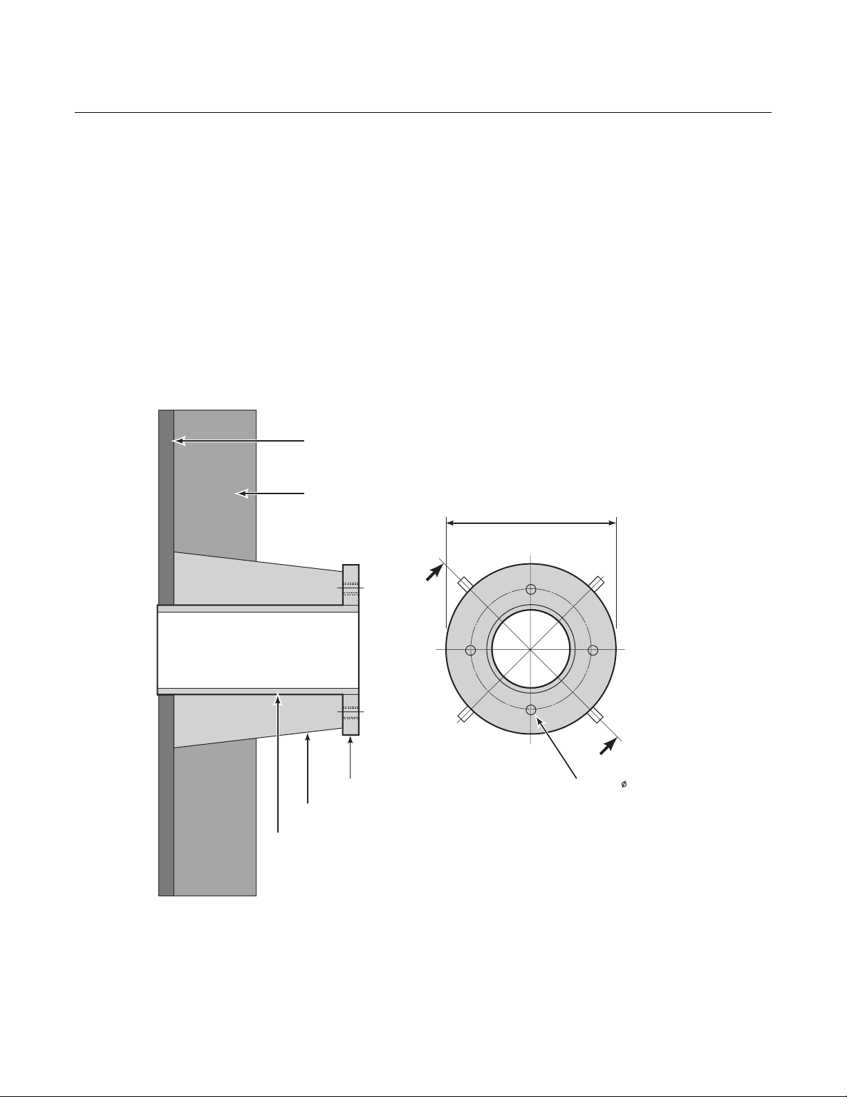
Figure 2-1. Site Mounting Flange
CCO 5500
A hole should be cut on either side of the duct to be measured; these holes
should accept a 'slip fit' with the stand-off pipe. The stand-off pipe should now
be welded into each hole and a mounting flange welded to each pipe with the
tapped holes positioned as shown in Figure 2-1 (it may be easier to weld the
pipe and the flange together before they are fixed to the duct). To avoid
vibration and movement, it may be necessary to fit spreader plates or bracing
fillets.
Alignment is satisfactory if one orifice can be clearly seen when viewed
through the stand-off pipe on the other side of the duct. It is suggested that
the stand-off pipe is 'tacked' on to the duct and the alignment checked visually
before a complete weld is made. The alignment of these holes is not critical,
as the integral adjustable mount compensates for up to 4
Duct Wall
o
of misalignment.
Lagging
Site Mounting Flange
Bracing Fillets
Stand-Off Pipe (if used)
3 in.(75 mm) dia. nominal
6.5 in.
(165 mm)
4 Holes M8
on 4.92 in. (125 mm)
Bolt Circle
2-5
Page 26
Instruction Manual
IM-106-5500, Original Issue
CCO 5500
August 2005
ISOLATING VALVES If isolating valves are used they mount directly onto the site mounting flanges.
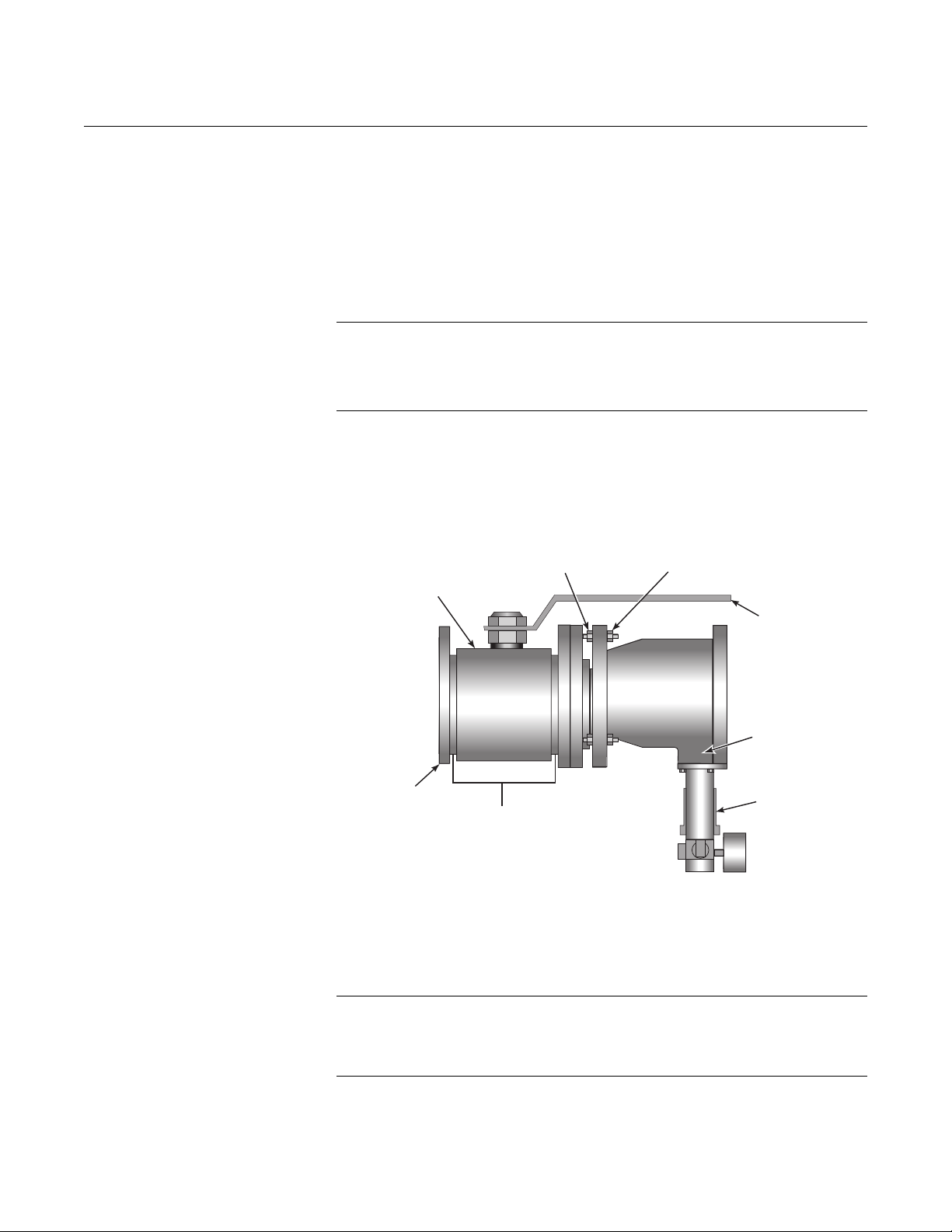
AIR PURGE The air purge mounts on the isolating valve. They are mounted by separating
the front flange from the air purge by unscrewing the four locking nuts. A
'snout' and o-ring arrangement locate into the front flange; work the two apart
carefully. The front flange should now be bolted to the isolating valve if used
or site flanges with a rigid gasket fitted between them, using the four
countersunk screws provided.
NOTE
Before mounting the air purges, ensure that air is supplied to the air purge
unit. If this precaution is not observed then the air purge and the
optical surfaces may be severely contaminated.
The adjustable flange is then positioned on the front flange, taking care that
the o-ring seal and 'snout' locate smoothly into the central aperture. This is
then secured by the four locking nuts that screw down onto the adjustable
flange. The arrangement should now appear as shown in Figure 2-2.
Figure 2-2. Valve and Purge Arrangement
TRANSMITTER AND RECEIVER
Locking Nuts
Valve Handle
Air Purge
Pressure Regulator
Assembly
Isolation Valve
(if used)
Site Mounting
Flange
Adjusting Nuts
Rigid
Gasket
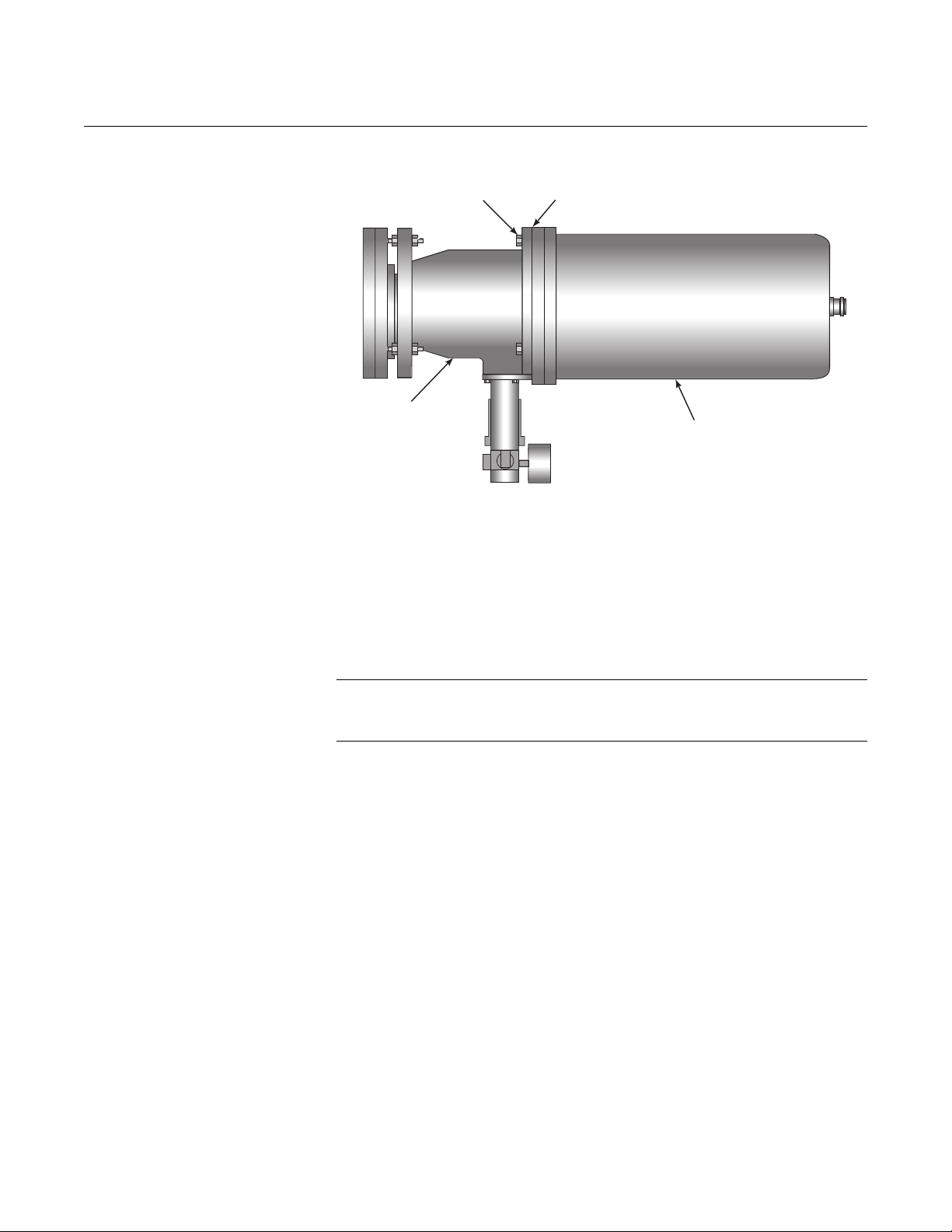
The transmitter and receiver attach to the rear face of the air purge with a
flexible gasket fitted between them, using the M6 x 20 hexagon head screws
provided (see Figure 2-3). A locating dowel ensures that the units can only be
attached to the air purge in one position - make sure this locates correctly.
2-6
NOTE
Before mounting the transmitter and receiver, ensure that air is supplied to the
air purge unit. If this precaution is not observed then the air purge and the
optical surfaces may be severely contaminated.
Page 27
Instruction Manual
IM-106-5500, Original Issue
August 2005
Figure 2-3. Analyzer Head Arrangement
Air Purge
Hexagon
Head Screws
CCO 5500
Flexible Gasket
Transmitter or
Receiver
AIR SUPPLY The purpose of the air purge is to keep the windows of the transmitter and the
receiver clean. Air may be supplied by one of three methods:
1. Negative pressure duct.
If the duct across which the instrument is measuring operates at a
negative pressure under all firing conditions, the air purge inlets may be
simply left open and the negative draft in the duct allowed to draw in
ambient air.
NOTE
For positive pressure ducts, they must be supplied with either compressed air,
or air from a blower.
2. Compressed air.
Using a fine flow regulator and filter, compressed air may be used to
provide the low flow required - an air supply of 14.7 psi (1 bar) is
required and the consumption is 2.2 cfm (1 liter/second) per purge.
3. Blower air.
A blower may be used to provide the air to the air purge - customers
may specify their own blower - it should be able to deliver 11 cfm (5
liters/second) per purge against the working pressure of the duct Rosemount Analytical can specify a blower if required.
2-7
Page 28

CCO 5500
Instruction Manual
IM-106-5500, Original Issue
August 2005
SIGNAL PROCESSOR UNIT
Figure 2-4. Signal Processor Unit/Power Supply Unit Mounting Detail
Cover Seal - Note that the
mounting holes are beyond
the extent of the seal
Assembled Box
110 mm Deep
9.1 in.
(230 mm)
Enough cable is supplied to mount the signal processor up to 33 ft (10 m)
from the receiver. To mount the signal processor (Figure 2-4), first remove the
cover by loosening the four captive screws, unplug the ribbon cable at the
connector on the lid PCB. Note that the processor case has a hinged lid. The
case is then secured to a firm support by use of the four mounting holes found
in the four corners of the case, outside the sealing rim. Since the mounting
holes are located outside the seal of the case, it is not necessary to seal the
mounting holes after installation, nor is it necessary to remove the circuitry
from the case for installation.
7.1 in.
(180 mm)
Cover
Base
4 Holes for M6
Mounting Screws
7.1 in.
(180 mm)
7.9 in.
(200 mm)
Approx. 6 in. (150 mm)
free space required
below box for cables
Cable Gland Entry
Blanking Plugs
2-8
Page 29

Instruction Manual
IM-106-5500, Original Issue
August 2005
CCO 5500
POWER SUPPLY UNIT Enough cable is supplied to mount the power supply up to a maximum of 33 ft
(10 m) from the transmitter. A maximum total cable length of 82 ft (25 m) may
be used to link the power supply to the receiver. These are the maximum
permitted lengths of cable and must not be exceeded.
Dimensions and mounting hole locations are identical to the signal processor
and are illustrated in Figure 2-4.
ELECTRICAL CONNECTIONS
Wiring should only be undertaken by a qualified technician.
Ensure that the power supply is isolated.
DO NOT switch power on until all installation work is complete and the system is ready for
configuring.
Installation of Cables Decide routing for all non-power cables (both those supplied by Rosemount
Analytical and those sourced locally). Use common routing wherever possible
and install leaving sufficient free-end length to make final connections.
Power cables should be installed separately, using different routes if possible
to reduce the risk of cross interference. Leave sufficient free-end length to
make final connections.
Rosemount supplied cables are provided with ferrite beads fitted to all cores
to protect against interference and should not be modified without consulting
Rosemount.
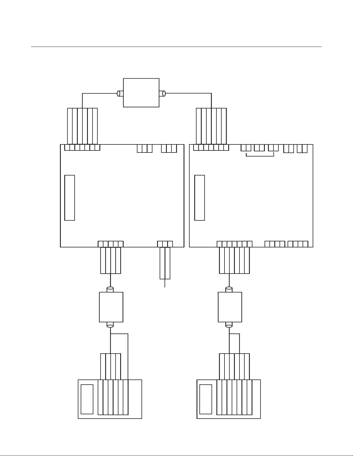
Cable Connections Overall system connections are illustrated in Figure 2-5.
2-9
Page 30
CCO 5500
Figure 2-5. System Cable Connections
TO SIGNAL
PROCESSOR
MOTOR DRIVE
REFERENCE WAVE
0V
+12V
ALARM CONTACT
DATA VALID
12345
MOTOR DIRECTION
6
7
2
0.5 mm
PVC COPPER
BRAID SCREEN
COMMON
W1
CABLE
8 CORE
INTERCONNECT
N/C
C1
COMMON
W2
N/O
O1
DATA VALID CONTACT
N/O
O2
ALARM CONTACT
N/C
C2
0V
DATA VALID
+12V SUPPLY
ALARM SIGNAL
12345
TO POWER
SUPPLY
MOTOR DRIVE
REFERENCE WAVE
6
MOTOR DIRECTION
OXYGEN
7
Instruction Manual
IM-106-5500, Original Issue
August 2005
4-20 mA (IN)0VTEMPERATURE
4-20 mA (IN)0VPRESSURE
4-20 mA (IN)
INPUTS
0V
13
PS1
PLANT STATUS
PS2
INPUT
+mA
ANALOG
8
9
101112
NORMALIZING
0mA
OUTPUT
POWER SUPPLY
8
BLUE
YELLOW
PVC COPPER
BLUE
YELLOW
9
101112
PURPLE
BLACK/WHITE
RED/BROWN
2
0.5 mm
8 CORE
BRAID SCREEN
PURPLE
BLACK/WHITE
RED/BROWN
SCREEN NOT TO BE GROUNDED
AT POWER SUPPLY
L
E
N
BLUE
GREEN/YELLOW
BROWN
50-60Hz
110V/220V
SIGNAL PROCESSOR
16
RED
RED
171819
BLACK
WHITE
BLUE
2
0.5 mm
PVC COPPER
BRAID SCREEN
BLACK
WHITE
BLUE
20
21
GREEN
YELLOW
PURPLE
8 CORE
SCREEN NOT TO BE GROUNDED
SCREEN
GREEN
YELLOW
PURPLE
TX+
22
AT SIGNAL PROCESSOR
23242526272829
SERIAL DATA
TX-
RX+
RX-
RX-
SERIAL DATA
RX+
TX-
TX+
30
2-10
TRANSMITTER
MOTOR DIRECTION
MOTOR DRIVE
REFERENCE WAVE
0V TO SOURCE
12V TO SOURCE
SCREEN
RECEIVER
+12V SUPPLY
0V
D1 SIGNAL
SIGNAL 0V
D2 SIGNAL
TEMP INPUT
SOLENOID DRIVE
Page 31

Instruction Manual
IM-106-5500, Original Issue
August 2005
CCO 5500
Section 3 Configuration and Startup
Introduction . . . . . . . . . . . . . . . . . . . . . . . . . . . . . . . . . . . . . page 3-1
Safety Considerations . . . . . . . . . . . . . . . . . . . . . . . . . . . . page 3-1
Power Supply Voltage Selection . . . . . . . . . . . . . . . . . . . . page 3-2
Turning the Power On . . . . . . . . . . . . . . . . . . . . . . . . . . . . page 3-2
Alignment . . . . . . . . . . . . . . . . . . . . . . . . . . . . . . . . . . . . . . page 3-2
Detector Levels . . . . . . . . . . . . . . . . . . . . . . . . . . . . . . . . . . page 3-4
Transmitter Adjustments . . . . . . . . . . . . . . . . . . . . . . . . . . page 3-7
Operating Parameters . . . . . . . . . . . . . . . . . . . . . . . . . . . . page 3-7
Current Output Calibration . . . . . . . . . . . . . . . . . . . . . . . . page 3-19
INTRODUCTION Configuring the instrument can take up to a couple of hours and consists of
the following operations:
1. Power supply voltage selection - select from either 110 or 220V supply.
2. Apply power - switch the power ON and observe the power supply rail indications.
3. Alignment - optically align the transmitter and receiver units using the integral adjustable mounts*.
4. Gain adjustment - adjust the gain within the receiver head and the signal processor*.
5. Operating parameters - set the operating parameters within the micro-processor for correct instrument operation.
6. Calibration - calibrate to a zero or an estimated gas concentration*.
7. Current output calibration - calibrate the analog current loop output.
8. Record the set-up and calibration data - it is strongly recommended that the operating parameters are recorded in Table 3-1, and the calibration data in Table 3-2.
SAFETY CONSIDERATIONS
NOTE
*These operations are preferably conducted when a clean stack condition
exists.
The mains power is supplied to the whole system via the power supply unit. If
any servicing or rewiring is to be performed ensure that the power supply is
isolated. For configuring the CCO 5500, the system needs power,
compressed air to the air purges and the isolating valves (if used) to be open.
3-1
Page 32

CCO 5500
POWER SUPPLY VOLTAGE SELECTION
Instruction Manual
IM-106-5500, Original Issue
August 2005
Disconnect and lock out power before removing the power supply cover.
With the mains supply switched OFF, unscrew the four captive screws on the
cover of the power supply and remove the cover. Select the correct supply
voltage using the sliding switch.
TURNING THE POWER ON
Once the supply voltage switch has been correctly set, switch the power ON.
Check that the power supply rail indication LED illuminates and that the LCD
display is functioning at the signal processor. Replace the lid of the power
supply.
After the initial power on and while the heated source is reaching
temperature, the display will show WAITING FOR REFERENCE. When the
source has reached an adequate temperature for the reference to be
detected, the message STABILIZING REF will be displayed, along with the
frequency and mark/space ratio - see diagnostic mode for details.
The reference frequency will take some time to stabilize (about 5 minutes
from cold startup). When it has been within tolerance for 10 consecutive
measurement cycles, the instrument will automatically change to the
operating mode - this is Mode 1 and is indicated by a number 1 appearing in
the top left hand corner of the LCD. The display will show a reading in ppm this is not accurate until configuration has been completed.
Allow 30 minutes before conducting the alignment procedure; this ensures
that the source temperature has stabilized.
ALIGNMENT In order for the instrument to operate satisfactorily, the transmitter and
receiver units need to be aligned. A degree of optical redundancy is built-in
and normal duct movements do not affect the operation of the instrument.
The transmitter and receiver need to be aligned. Remove the receiver from its
air purge and align the transmitter so the red light it emits can be seen at the
other side of the duct (through the receiver purge). Then replace the receiver
and align, using as a guide, the detector levels displayed by the signal
processor in Mode 5. Finally, the transmitter adjustment is 'fine tuned' once
again using the detector levels in Mode 5. All these processes are described
in the following steps.
3-2
1. Remove the receiver from its mounting flange. Adjust the alignment of
the transmitter flange until the bright red disc of the transmitter is
located centrally in the field of view, when viewed from the receiver air
purge. Use the adjusting nuts to alter alignment. First adjust in one
plane (using opposite nuts) then adjust in the other plane. Lock the
transmitter flange with the locking nuts.
2. Adjustments to the alignment are made using the four adjusting nuts, and the flange is locked in position using the locking nuts - these are illustrated in Figure 3-1.
Page 33

Instruction Manual
IM-106-5500, Original Issue
August 2005
Figure 3-1. Adjusting Nuts for Alignment
CCO 5500
ADJUSTING NUTS
FRONT FLANGE
REAR FLANGE
3. Replace the receiver on its air purge. The next adjustment is done using the detector levels as viewed from the signal processor.
4. To change mode on the signal processor the MODE key needs to be pressed once to access each mode. Enter SET UP MODE (Mode 5) by pressing the MODE key 4 times. 5 SET UP will then be displayed on the LCD. Press ENTER to access the mode.
5. Because Mode 5 is used to configure the instrument, a security code is
used to prevent any unauthorized alteration of settings. The default
code set at the factory is 0000. The cursor will flash over the first digit
that should be altered using the arrow keys until the desired number is
displayed, press ENTER and the cursor will move onto the second digit.
Similarly alter and press ENTER when the desired number is displayed.
When the fourth digit has been correctly entered the processor will
enter Mode 5.
6. Within Mode 5 select the CALIBRATE menu using the arrow keys. Press ENTER when calibrate is displayed.
7. Once again, use the arrow keys to select DISPLAY DETECTOR
LEVELS option and press ENTER to access. The D1 and D2 detector
levels will be displayed. Important - if not in this mode, the gas cell at
the source will periodically interrupt the IR beam and make alignment
difficult.
8. Adjust the alignment of the receiver by using the adjusting nuts. As for
the transmitter, the alignment is best conducted by adjusting in one
plane first, then in the other. As a 'rule of thumb', it will be observed that
the D2 detector level will be affected to a greater extent by adjustment
in one particular plane. Similarly, the D1 detector level will be affected
more by adjustment in the other plane.
9. Use this guide to ensure that the MAXIMUM possible values of both D1 and D2 are reached. After alignment has been achieved, lock the flange into position using the locking nuts.
10. If the displayed detector level is below 5000, increase the gain from the signal processor to about 10,000; if above 15,000, reduce to 10,000. Refer to Detector Levels for details of this operation.
LOCKING NUTS
3-3
Page 34

IM-106-5500, Original Issue
CCO 5500
NOTE
The alignment of the receiver unit is important. Take time to ensure that
maximum values of D1 and D2 are obtained.
11. To 'fine tune' the alignment, return once more and adjust the transmitter flange, again observing the values of D1 and D2 as appropriate; lock the flange in place when a MAXIMUM has been obtained.
12. After this procedure has been followed, the alignment is completed and there is rarely any need for further adjustments.
NOTE
The alignment of the receiver may be conducted by monitoring the output of
the detector directly. This can be done using a voltmeter set to AC volts (10V
max.) measuring across test points S0V and S2 for D3 and S0V and S1 for
D1 on the RECEIVER CONTROL BOARD within the receiver (Figure 3-3).
This is useful should the receiver be some distance from the signal processor.
DETECTOR LEVELS The gain of the detector signals is set in two locations:
Instruction Manual
August 2005
Receiver Gain Adjustment
1. In the receiver: two potentiometers set the gain. Refer to Receiver Gain Adjustment.
2. In the signal processor: trim potentiometers adjust the level of the D1 and D2 signals before they enter the microprocessor. Refer to Receiver Gain Adjustment.
It is essential that the alignment procedure has been conducted and a
maximum detector signal obtained before attempting to optimize the detector
levels.
To give an optimum signal-to-noise ratio, the detector levels must be
maximized.
For the best signal-to-noise ratio, the gain of the detector signals within the
receiver must be set to a maximum, without saturating. The gains will have
been set by Rosemount Analytical at a pathlength of 6.5 ft (2 m). If the
pathlength is above 13 ft (4 m) or below 5 ft (1.5 m), this adjustment may be
necessary to optimize the detector levels. If the pathlength is within this
range, this section may be ignored unless there is insufficient or too much
gain.
1. Enter the Setup mode, CALIBRATE OPTION-SET DETECTORS, and display the value of D2/D1.
2. Loosen the cable gland and remove the end cap from the receiver body, letting the cable slip through the gland.
3. The receiver can now be accessed as shown in Figure 3-2.
3-4
Page 35
Instruction Manual
IM-106-5500, Original Issue
August 2005
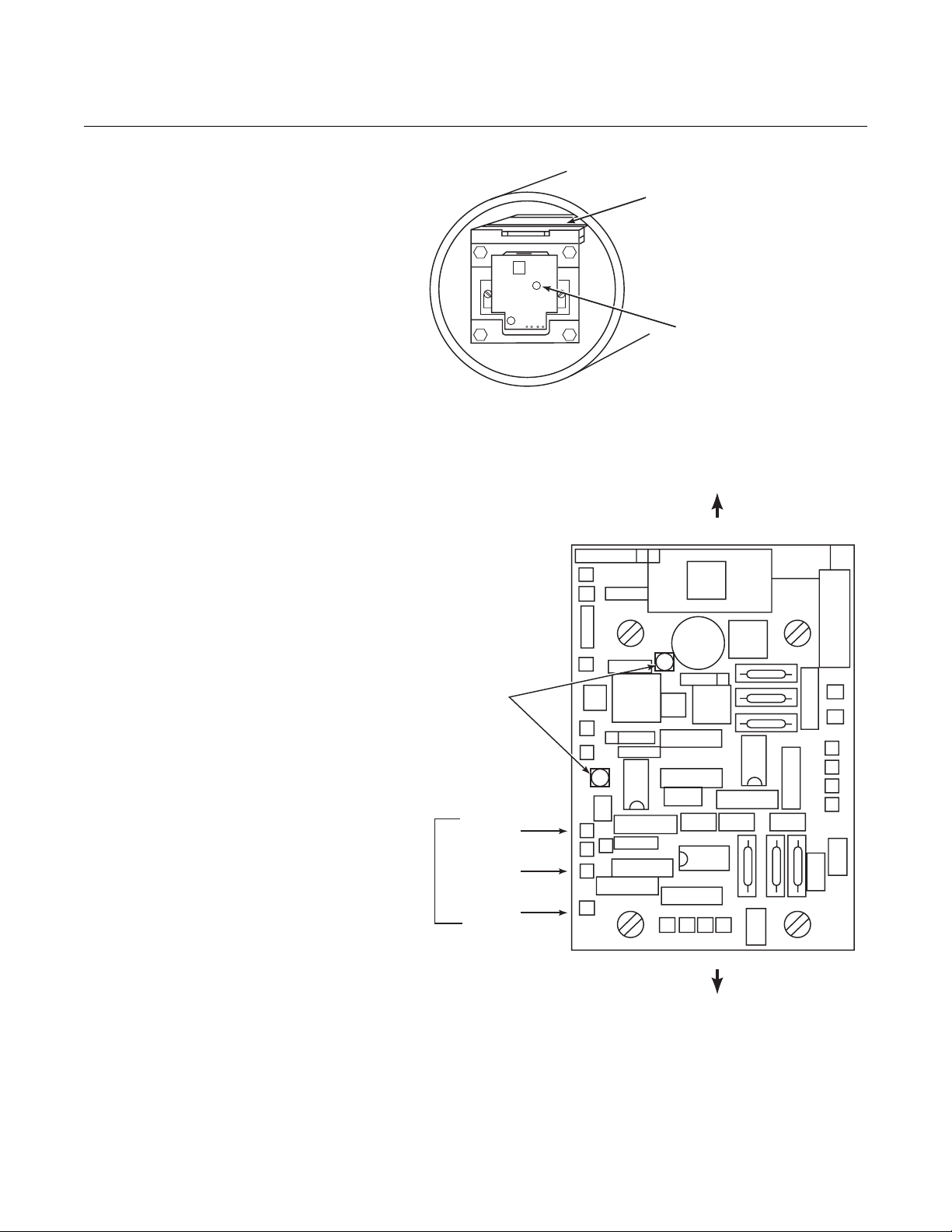
Figure 3-2. Receiver Trim Pots
Figure 3-3. Receiver Test Points
CCO 5500
Control Board for
Side Detector D1
Control Board for
End Detector D2
4. Trim potentiometer(s) set the gain with the receiver. Levels should be measured with a voltmeter set to AC Volts.
TEST POINTS
Front of Receiver
Voltage
Indication
LEDs
S0V GREEN
S2 BLUE
S1 WHITE
End Detector
5. Connect the voltmeter to the S0V and S1 test points, as in Figure 3-3. Increase the gain using the trim pot at the END DETECTOR, until the voltage is a maximum of 4V rms.
6. Repeat the above procedure for the SIDE DETECTOR, measuring across S0V and S2 test point.
7. When the detector levels are satisfactory, replace the cover.
3-5
Page 36

CCO 5500
Instruction Manual
IM-106-5500, Original Issue
August 2005
NOTE
If the duct is operating and a high opacity may be present, reduce the set
voltages to 2V rms maximum. This is to prevent saturation should the opacity
level drop.
Signal Processor Gain Adjustment
Figure 3-4. Gain Adjustment Potentiometers
TRIM POT.
TEST POINT
LED
TRIM POT
TEST POINT
LED
After the detector level(s) at the receiver have been optimized if necessary,
the levels within the micro-processor should be adjusted. This adjustment is
conducted by means of two trim potentiometers within the signal processor,
Figure 3-4.
CON3
D2 TRIM
POT
D1 TRIM
POT
VIN
+V1
-V1
COUNT 1P
COUNT 3
T4
SOL MDRV
M-DIR
F
COM4
T7
T10
T6
T5
T8
T9
T3
T2
T1
-15
+12VB
0VB
REG
+15
+5
0V
5V
12V
+15V
-15V
0VA
0V1
-15V1
+15V1
3-6
+12V
PS
PS1
PS2
PLANT
STATUS
INPUT
+mA 0mA
ANALOG
OUTPUT
2A
POWER SUPPLY NOT USED
SB
FUSE
1 2 3 4 5 6 7 8 9 10 11 12 13 14 15
16 17 18 19 20 21 22 23 24 25 26 27 28 29 30
RECEIVER SERIAL DATA
NORMALIZING IPs
1. *Set the gain to a minimum by turning the D2 - detector trim potentiometer within the signal processor fully CLOCKWISE - it is a 20-turn pot.
2. *Enter the DIAGNOSTIC MODE - DETECTOR LEVELS option, and display the values of D2 and D1. Turn the trim pot COUNTERCLOCKWISE until the D2 level is between 12,000 and 15,000. Allow time between adjustments for the readings to settle.
Page 37

Instruction Manual
IM-106-5500, Original Issue
August 2005
CCO 5500
NOTE
If the duct is operating and the opacity levels are high, reduce the D2 level to
about 8,500. This is to avoid saturation should the opacity level within the duct
reduce.
3. *To ensure that the detector signal is not saturating, observe the
saturation count signal displayed next to the detector levels. If a SAT #
of more than 0 is displayed, turn the trim pot slightly to reduce the gain
until a SAT # of 0 is displayed.
4. *Should saturation be indicated, with trim pot turned fully CLOCKWISE, reduce the gain in the receiver and repeat the procedure.
5. Repeat the steps above marked (*) for the D1 level, using the D1 trim potentiometer.
NOTE
The circuits are designed so that wherever saturation occurs (receiver or
processor), it will always be detected by the micro-processor. If the displayed
detector levels cannot be set to within this band or saturation cannot be
avoided, the detector levels should be optimized at the receiver. Refer to
Receiver Gain Adjustment.
TRANSMITTER ADJUSTMENTS
NOTE
It is recommended that Rosemount Analytical is consulted before making any
adjustments within the transmitter.
Two trim potentiometers within the transmitter unit allow adjustments to be
made to the intensity of the source and the frequency of the chopper motor.
These are set up at the factory and rarely need adjustment.
NOTE
Increasing source intensity may severely reduce the source life.
Source Intensity A trim pot, in the rear of the unit (furthest from the lens) is accessible after the
end cover has been removed. This allows adjustments to be made to the
intensity of the source.
Chopper Frequency Remove the head from the duct to conduct this process. A trim pot. in the front
of the unit (nearest to the lens) is accessible after the front flange has been
removed (achieved by loosening and removing the four screws holding the
flange in place). Once removed, the trim pot. is revealed. This allows
adjustments to be made to the frequency of the chopper motor.
OPERATING PARAMETERS
Operating parameters must be set in the instrument for it to function correctly.
All operating parameters are set within the signal processor during the setup
mode, where they are held in non-volatile memory and so retained in the
event of a power loss.
Even if the measured data is not going to be normalized the normalizing
parameters must be set for the instrument to function properly.
3-7
Page 38

CCO 5500
Instruction Manual
IM-106-5500, Original Issue
August 2005
NOTE
All operating parameters are entered in the setup mode.
Section 5, Normal Operation, lists all parameters in full. Basic details are
given here for configuration purposes.
To aid configuration and to record any subsequent changes to the operating
parameters, it is recommended that Table 3-1. Instrument Settings, at the end
of this procedure be completed to provide a record of the instrument setup.
1. Press the MODE key until the number 5 is displayed in the top left-hand corner.
2. Enter 0000 for the security code - this is the default code set at the factory.
3. After the correct code has been entered the six sub-modes are accessed by using the ARROW keys and pressing ENTER when the required option is displayed.
4. First the instrument averages need setting. a. Press the ENTER key when this
display is shown, the display will now
show one of the averages. Use the
ARROW keys to select the average time
that requires setting, and press the ENTER key to access the value.
Change the value by using the ARROW keys and input by pressing the
ENTER key.
b. Set the seconds averaging stack to the required value. This is limited
to within 10 to 60 seconds in 10-second intervals.
c. Set the minutes averaging stack to the required value. This is limited
to within 1 to 60 minutes in 1-minute intervals.
d. Set the hours averaging stack to the required value. This is limited to
within 1 to 24 hours in 1-hour intervals.
e. Set the days averaging stack to the required value. This is limited to
within 1 to 30 days in 1-day intervals.
5. The analogue current loop output is set
up in the next menu. Press the ENTER
key while this display is shown to select
it, then press the ARROW keys to step
through the available options. Press the ENTER key to enter each
option and change the displayed parameter.
a. Base of Output
5 SET AVERAGES
5 CONFIGURE O/P
3-8
An origin of 0 or 4mA can be set for
the current loop output. The ARROW
keys will 'toggle' between these two
options. Press the ENTER key to enter
the new value.
b. Averaging Time of the Output
5 CONFIGURE O/P
OUTPUT = 4 to 20 mA
Page 39

Instruction Manual
IM-106-5500, Original Issue
August 2005
CCO 5500
Any of the four averaging stacks
(seconds, minutes, hours or days)
may be used for the analog output.
They are selected by the ARROW
keys and entered using the ENTER key.
c. Output Units
The analog output can represent the
gas concentration in units of either
3
mg/m
, mg/Nm3 or ppm. The ARROW
keys will 'toggle' between these three
options. Press the ENTER key to enter the new value.
d. Output Span
Select the required span using the
ARROW keys for each digit. The
ENTER key is pressed to enter the
value of each digit. The units will be
displayed as either ppm, mg/m
been selected beforehand. The current value will be displayed for 1
second when this option is entered. The display then defaults to
zero; thus the span value must be re-entered for the unit to function
correctly.
e. Fault Indication
Should a fault condition occur, the
current output of the instrument may
be set to any of the following options:
3
or mg/Nm3, depending on what has
5 CONFIGURE O/P
Average 01m
5 CONFIGURE O/P
Units mg/m3
5 CONFIGURE O/P
Span 0000mg/m3
5 CONFIGURE O/P
Fault cond ZERO
• Set the output at 0 mA - ZERO.
• Adjust the output to the calculated gas concentration even though
a fault condition exists - MEAS.
• Hold the last calculated gas concentration - HOLD.
• Set the output to full scale (20 mA) - F.S.
One of these options can be selected by pressing the ARROW keys;
when the desired option is displayed press the ENTER key.
f. Set mA Output
NOTE
This is set at the factory and should not be altered without due consideration.
From this option the current levels of
the analog output are set up. Press the
ENTER key to select it, and the
operator is prompted to set the current
levels at 0 and 20 mA.
When this is displayed, the current output should be set to 0mA as
measured with a calibrated current meter across the analog current
loop terminals; nothing else should be connected to these terminals
when the output is being set up.
5 CONFIGURE O/P
Set Zero (007)
3-9
Page 40

CCO 5500
Instruction Manual
IM-106-5500, Original Issue
August 2005
The value is adjusted using the two arrow keys, the UP arrow will
take the current output up, and the DOWN arrow will take it down.
Press the ENTER key when the correct output current is displayed
on the ammeter.
NOTE
Zero mA should be set up no matter what has been selected as the base of
the current output. This is factory set by Rosemount Analytical.
g. In a similar manner to the above, the
current output level should now be set
to 20 mA.
6. The next menu to be configured is the Parameters menu - options are given below.
Select this option by pressing the ENTER
key. The ARROW keys will now display
the available options from within this
sub-mode, when the option that requires
changing is displayed, press the ENTER key. When all required
changes have been made, select the EXIT option and press ENTER.
a. Security Number
To prevent any unauthorized
tampering with the set up information,
it is important that the security code is
changed from the factory setting. Each
digit is selected with the ENTER key and changed with the ARROW
keys.
NOTE
It is important to make a note of this number, otherwise it will not be possible
to change the instrument setup.
5 CONFIGURE O/P
Set span (247)
5 PARAMETERS
5 PARAMETERS
Security # 0000
3-10
b. Identity Number
If the system is being used as part of
an integral monitoring system and the
serial input and outputs are being
used, the central processor requires a
'Device Identity' to identify each instrument. This number must be
unique for each equipment item and can be set from 1 to 30 as
required. See the IEM Communication Equipment Manual (Doc. ID:
0006/6) for details.
c. Measurement Path Length.
NOTE
The current value entered for the path length will be displayed for 1 second
then the display will default to zero. The path length must be re-entered for
the unit to calculate gas concentrations correctly. (The display following
shows the screen after 1 second, before the path length is reconfigured).
5 PARAMETERS
Identity # 30
Page 41

Instruction Manual
IM-106-5500, Original Issue
August 2005
CCO 5500
The transmissivity of a sample of any
gas depends both on the
concentration and on the path length
through which the radiation is
transmitted. Similarly, the output of the CCO 5500 monitor also
depends on the path length of the flue gas through which the
radiation is transmitted.
Refer to “Points to Consider” on page 2-4.
The Rosemount Analytical analyzers are sensitive to the product of
concentration x path length, and in order to obtain a true value of
concentration of gas, it is necessary to input the correct path length
into the processor. This value is then used to produce a final value of
gas concentration.
NOTE
The path length entered must represent the length of the actual gas pass, not
the flange-to-flange dimension between the transmitter and receiver.
d. Alarm
A contact output is available to warn of
a high gas concentration. This contact
output may be triggered from any of
the four averaging stacks. Select its
source with the ARROW key and enter it with the ENTER key.
5 PARAMETERS
Path length 0000mm
5 PARAMETERS
Alarm source 15m
Select the units for the alarm - these
may be different to the units selected
for the analog output.
After the source has been selected,
the instrument requires a level at
which the output will be triggered. Set
the desired level with the ARROW
keys.
e. Cal Factor
NOTE
Do not enter this mode without recording the original cal factor as displayed in
mode 4. The Cal factor will be lost when this menu option is entered.
During the calibration routine, the
instrument calculates a 'Cal Factor'
which sets the basic calibration of the
instrument. This value may be
changed from this mode.
5 PARAMETERS
Alarm mg/Nm3
5 PARAMETERS
Alarm 0000mg/Nm3
5 PARAMETERS
Cal Factor
3-11
Page 42

CCO 5500
Instruction Manual
IM-106-5500, Original Issue
August 2005
NOTE
As this value controls the calibration of the instrument do not change it without
due consideration.
f. Plant Status Input
Used to determine whether the plant is
operating under correct conditions.
There is a choice of three controls for
plant status, only one can be used to
control plant status at any one time; logic input, serial input and
multiple input. The multiple input has five sub options; temperature
threshold, oxygen threshold, water vapor threshold, detector level
threshold and logic input. Any or all of these five options (in the
multiple option) may be selected to determine plant status.
g. Logic Input
If the PS1 and PS2 terminals are linked in the signal processor the
logic contact is made and the plant status is OFF. These terminals
may be linked manually during a plant shut down, or they may be
wired to a switch/contact outside the unit (e.g. a valve that opens and
closes the duct). Press ENTER when the logic screen is displayed if
this option is required.
h. Serial Input
If this option is selected the criteria controlling plant status are
transmitted via the serial data link. Press ENTER on viewing the
serial screen if this option is required to determine plant status.
i. Multiple
Press ENTER when the multiple display is seen and scroll through
the following options. Select YES or NO for each option depending
on whether it is to be used to determine plant status. If YES is
chosen the configuration screen for that option will be shown. Enter
the required value and press ENTER. The next option will then be
shown, similarly select YES or NO and so on. After the final option
(Logic Input) has been configured the display will revert to 'Multiple'.
Scroll down using the arrow key and when EXIT is viewed press
ENTER. The plant status is thus configured.
5 PARAMETERS
Plant Status I/P
3-12
j. Temperature Threshold
A value is set here for the temperature
threshold. While the temperature
(taken from the normalizing
temperature) is above the threshold
value, plant status is ON. If the temperature drops below the
threshold, plant status is OFF and only the seconds averaging stack
will update.
5 Plant Status I/P
T th’hold 262
o
F
Page 43

Instruction Manual
IM-106-5500, Original Issue
August 2005
CCO 5500
k. Oxygen Threshold
Set and used in a similar manner to the temperature threshold.
However, if the normalizing oxygen level rises above the threshold,
plant status is OFF. For plant status ON, the oxygen level must be
below the threshold set.
l. Water Vapor Threshold
Set and used in a similar manner to the temperature threshold. If the
water vapor falls below the threshold plant, status is OFF. For plant
status to be ON, the water vapor must be above the threshold set.
m.Detector Threshold
Set and used in a similar manner to the temperature threshold.
However, if the detector level rises above the threshold, plant status
is OFF. For plant status ON, the detector level must be below the
threshold set. Only used for the NO
n. Logic Input
Either selected as YES or NO - depending on whether the logic
contracts (PS1 and PS2) will be used to indicate plant shut down.
analyzer.
x
7. Normalization
All of the normalization inputs and
parameters are set up from this mode.
Press ENTER to access the mode and
the ARROW keys will select which of the
normalizing inputs are to be changed, they are :
• Temperature
• Oxygen
• Pressure
• Water Vapor
After selecting the normalizing parameter, the user may set the
standard levels to which the measurement is to be normalized, and how
the instrument reads the value, i.e., fixed keypad input, 4-20 mA input,
or on the serial data line.
After selecting the parameter to be set up, the ARROW keys will select
between entering the standard levels, and how the normalization data
is to be brought into the instrument.
a. Set Standard Levels
Each normalizing parameter
normalizes the measured gas
concentration to standard conditions of
temperature, oxygen, pressure and
water vapor. These levels are set from within this option. Use the
ARROW keys to change each displayed normalizing standard value.
5 NORMALIZATION
5 TEMP DegF
std level = 000
3-13
Page 44

CCO 5500
Instruction Manual
IM-106-5500, Original Issue
August 2005
b. Set Values
The normalizing data can be brought into the instrument in one of 3
ways:
1
By entering a fixed value via the keypad. This is suitable where the value is stable to about ±5%.
2
If an INPUT UNIT is being used, all normalizing data can be transmitted via the serial data line.
3
Using the 4-20 mA inputs within the processor to receive a measurement transducer data. The values at 4 mA and at 20 mA will be requested should this option be selected.
With an integrated system the lead analyzer should have its
normalizing parameters set to the 4-20 mA inputs. All the other
analyzers must then be set to serial and the normalization
parameters will be transmitted down the serial data highway.
5 TEMP DegF
Keypad Input
5 TEMP DegF
Serial Input
5 TEMP DegF
Analog Input
c. Temperature
An analog input should always be used for temperature correction this ensures that the flue gas temperature is being measured
continuously and accurately. Connect the analog output of the
temperature transducer into the Rosemount Analytical analyzer, and
select the analog input option. This value is used to normalize the
gas concentration measurement, and to correct for the effects of
temperature on the IR absorption spectrum.
If a fixed value input is used, then at flue gas temperature higher than
o
572
F (300oC) the compensation algorithm will become less precise
and instrument accuracy will deteriorate accordingly. This is not
recommended.
NOTE
If normalization is not required, the instrument must hold the temperature of
the gas in the duct - analog input.
d. Oxygen
To correct the data to standard levels of oxygen, an estimate of the
oxygen at the point of measurement is required. If the oxygen level is
being continuously measured, connect the analog output of the
oxygen analyzer into the CCO 5500 analyzer, and select the analog
input in the normalization menu. This input must be defined as either
WET or DRY, depending on how the measurement is made. After the
wet or dry has been defined the analog input values need defining,
set the 4 mA and 20 mA values. If the oxygen level is relatively
constant through all firing conditions, then a fixed (keypad) input may
be used.
3-14
Page 45

Instruction Manual
IM-106-5500, Original Issue
August 2005
CCO 5500
NOTE
If normalization is not required, the instrument must have the normalizing
parameters for oxygen set.
With an integrated system the pressure data can be taken to the
instrument via the serial data line.
e. Pressure
To correct the data to a standard pressure - normally 14.65 psi (101
kPa), the pressure at the point of measurement needs to be
determined. If the flue pressure is relatively constant through all firing
conditions, then a fixed input may be used. If the pressure is not
constant, it should be measured and brought into the instrument via
the 4-20 mA input within the processor.
NOTE
If normalization is not required, the instrument must have the normalizing
parameters for pressure set to 14.65 psi (101 kPa)(standard level and keypad
input).
With an integrated system the pressure data can be taken to the
instrument via the serial data line.
f. Water Vapor
An 'across the duct' monitor measures the gas concentration under
wet conditions, that is, unlike a sampling system, the gas has not
been preconditioned in any way before the measurement is made.
To normalize it to dry conditions, when the water vapor present is of
a known and relatively fixed level, set the standard level to DRY, and
use a fixed value in the keypad option representing the expected
water vapor produced for the fuel type. If the measurement is not to
be normalized for water vapor, set the standard level to WET.
8. Reset Averages
The average values that are currently
held in the averaging stacks will not be
accurate as configuration has not yet
been completed, these therefore need
resetting using this option. This process will erase the current average
that is held in all of the averaging stacks. Select this option by pressing
the ENTER key and using the Arrow keys.
NOTE
Confirmation is requested before the averages are reset.
5 RESET AVERAGES
If this option is selected after the instruments' first configuration, all data
in the averaging stacks is reset, and the data for as much as the last 30
days will be lost.
3-15
Page 46

CCO 5500
Instruction Manual
IM-106-5500, Original Issue
August 2005
9. Calibration
From this option the two detector levels
may be displayed and a basic calibration
conducted. During Set Detectors the gas
cells are not moved; this gives an
immediate response for setting up the detector levels. The basic
calibration of the instrument is set by a 'CAL FACTOR' which is
calculated during a calibration routine. Press the ENTER key while this
is displayed and the following options are available.
a. Set Detectors
Both the D1 and D2 levels from the
receiver are displayed, and saturation
counts are also displayed. To give an
immediate response to any alterations
that are required, the gas cells are not moved during this operation.
b. Span Adjust
NOTE
The Span Factor is set at the factory by Rosemount Analytical; Do not adjust
it unless the instrument sensitivity is suspected. It is recommended that
before adjustments are made, the original value is recorded.
Instrument sensitivity can be adjusted
if a known concentration of
measurement gas exists between the
transmitter and receiver units, and
instrument sensitivity is suspected. If a problem arises with this,
please consult Rosemount Analytical.
5 CALIBRATE
5 D2 = 10534 # = 00000
D1 = 15000 # = 00000
5 Val = 250 –> 250ppm
Span Factor 1000
The Span Factor may need adjusting if new gas cells or filters have
been fitted.
Refer to Span Factor Adjustment.
c. Calibrate
Re-enter Mode 5 Calibrate menu and
proceed to the calibrate option. The
basic calibration of the instrument can
be calculated from this routine. It is
preferable to conduct this operation with the plant shut down to
ensure a zero gas concentration within the duct. If this is not
possible, however, the instrument can calibrate to a known value of
the gas concentration - the calibration target.
5 CALIBRATE
Calibrate
3-16
Page 47

Instruction Manual
IM-106-5500, Original Issue
August 2005
CCO 5500
Set the calibration target either to a
known value of the gas concentration
or to zero, and set the desired number
of cycles over which the calibration
factor is determined (a minimum of 30 is recommended). The
calibration should now be run and the display will show a count down
during its execution. When the calibration is complete the new "Cal
Factor" will be displayed for about 5 seconds and the instrument will
exit the calibration routine.
NOTE
The calibration routine must be run during commissioning, otherwise the
instrument will not be able to calculate the true level of gas within the duct.
5 CALIBRATE
Target 0000ppm
5 CALIBRATE
Set # cycles = 30
5 cycle # 30
CAL IN PROGRESS
5 CAL COMPLETE
Cal FACT K = 9054
Do not run the calibration routine unless reasonable conditions exist in
the duct. If it is not the initial calibration, it is recommended that the Cal
Factor is recorded from the parameters option, before the calibration is
run.
To aid configuration, and to record any subsequent changes to the
operating parameters, Table 3-1 lists all of the options available, and
can be used as a record of the operating parameters.
3-17
Page 48

CCO 5500
Table 3-1. Instrument Settings
Parameter Config.
Averages Seconds
Minutes
Hours
Days
Output 0 or 4 mA base
Units
Average
Fault condition
Parameters Path Length
Alarm source
Alarm units
Alarm levels
Normalization Temperature
Standard level
o
I/P
F (oC) @ 4 mA
o
I/P
F (oC) @ 20 mA
Keypad input
Serial input
Oxygen
Standard level%
Wet or dry gas
I/P % @ 4 mA
I/P % @ 20 mA
Keypad input %
Serial input
Pressure
Standard level psi (kPa)
I/P psi (kPa) @ 4 mA
I/P psi (kPa) @ 20 mA
Keypad input
Serial input
Water vapor
Standard level (wet %/dry)
Keypad input %
Measured value
o
F (oC)
o
C (not ideal)
Instruction Manual
IM-106-5500, Original Issue
August 2005
3-18
Page 49

Instruction Manual
IM-106-5500, Original Issue
August 2005
Table 3-2. Calibration Data
CCO 5500
After the calibration has been conducted, a CAL FACTOR will be
calculated; this determines the calibration of the instrument. The cal
factor will be displayed for a few seconds after a calibration has been
conducted, and it can also be interrogated from Mode 4 (diagnostic
mode). Enter the cal factor into the table below, as a record of
instrument operation.
Calibration Data
Detector Outputs Factory Config
D2
D1
E1
E2
Calibration Data
Cal factor
Span factor
Output Calibration
Set zero
Set span
CURRENT OUTPUT CALIBRATION
NOTE
Factory settings were obtained under the following conditions:
• 6.5 ft (2 m) path length
• Clean conditions
• 240V, 50 Hz supply
NOTE
This is set at the factory and should not be altered without due consideration.
The current output should now be set up using a calibrated milliammeter set
to DC current, 20 mA max. Conduct this procedure as follows :
1. Connect the milliammeter to the output terminals within the signal processor - terminals +mA and -mA.
2. Enter the SET UP MODE - CONFIGURE OUTPUT - SET ZERO
OPTION, and adjust the level using the ARROW keys until 0mA is
recorded. Record the value in brackets on the display in Table 2 Calibration Data.
3. Enter the SETSPAN option and adjust the level using the ARROW keys until 20 mA is recorded. Record the value in brackets on the display in Table 2 - Calibration Data.
3-19
Page 50

Instruction Manual
IM-106-5500, Original Issue
August 2005
CCO 5500
3-20
Page 51

Instruction Manual
IM-106-5500, Original Issue
August 2005
Section 4 Normal Operation
Introduction . . . . . . . . . . . . . . . . . . . . . . . . . . . . . . . . . . . . . page 4-1
Normal Startup Procedure . . . . . . . . . . . . . . . . . . . . . . . . . page 4-1
Modes of Operation . . . . . . . . . . . . . . . . . . . . . . . . . . . . . . page 4-2
Key Operation . . . . . . . . . . . . . . . . . . . . . . . . . . . . . . . . . . . page 4-3
Program Tree . . . . . . . . . . . . . . . . . . . . . . . . . . . . . . . . . . . . page 4-3
Operating Mode . . . . . . . . . . . . . . . . . . . . . . . . . . . . . . . . . page 4-5
Parameter Mode . . . . . . . . . . . . . . . . . . . . . . . . . . . . . . . . . page 4-5
Normalization . . . . . . . . . . . . . . . . . . . . . . . . . . . . . . . . . . . page 4-6
Diagnostic Mode . . . . . . . . . . . . . . . . . . . . . . . . . . . . . . . . . page 4-6
Check Cell Mode . . . . . . . . . . . . . . . . . . . . . . . . . . . . . . . . . page 4-20
Normal Shutdown Procedure . . . . . . . . . . . . . . . . . . . . . . page 4-21
Routine Checks . . . . . . . . . . . . . . . . . . . . . . . . . . . . . . . . . . page 4-21
CCO 5500
INTRODUCTION After the CCO 5500 has been configured, it will measure the gas levels
between the transmitter and receiver and produce an output proportional to
the gas levels. An integral 32-character display also shows the calculated
levels.
The CCO 5500 allows the operator to interrogate the micro-processor to
observe the system parameters and to change them if required.
A menu-based program is used and access is gained by four keys mounted
on the lid of the signal processor.
Measurement Once configuration has been completed, the absorption of IR radiation is
measured and a parameter 'Y' is calculated - refer to “Principles and Modes of
Operation” on page 1-4. This value is used to produce a final concentration of
gas that can be normalized to standard conditions and averaged over a time
ranging from 10 seconds to 30 days.
The instrument computes four averages, any of which can be used to drive
the analog output, or displayed on the integral 32-character LCD.
Calibration During the configuration procedure a calibration is conducted that sets the
system gains to produce a zero or known gas level. Once the routine has
been conducted the calibration of the instrument is fixed by precision filters,
which do not change.
NORMAL STARTUP PROCEDURE
Power-up the system and wait for 30 minutes. This allows time for the infrared
source to heat up. Once the receiver is detecting a signal a reading will be
seen on the signal processor display. This should be in normal operating
mode, Mode 1 (shown by a number 1 at the top left corner of the LCD); a
reading in vpm, mg/m
functioning properly.
3
or Nmg/m3 will be shown. If this appears, the system is
4-1
Page 52

Instruction Manual
IM-106-5500, Original Issue
CCO 5500
August 2005
MODES OF OPERATION The instrument has six modes of operation identified by a number in the top
left corner of the display:
Mode 1 - Operating Mode
Displays average gas concentration.
Mode 2 - Parameter Mode
Displays operating parameters.
Mode 3 - Normalization Mode
Displays normalization data.
Mode 4 - Diagnostic Mode
Investigates instrument operation. Self checks are continually made by the
instrument; should a complication exist, this mode will automatically be
selected and the fault displayed on the display.
Mode 5 - Setup Mode
Sets operating parameters. The opening parameters must be entered for
the instrument to function correctly. This mode can only be accessed using
a security code.
Figure 4-1. Keypad
Mode 6 - Check Cell Mode
Used to verify the instruments’ operation and calibration.
NOTE
The outputs of the instrument are unaffected by key operation in all modes
except the setup mode.
32 Character
Liquid Crystal Display
Key Panel
Mode
Enter
Data Valid and
Alarm LEDs
4-2
AlarmData Valid
Page 53

Instruction Manual
IM-106-5500, Original Issue
August 2005
CCO 5500
KEY OPERATION Each mode is accessed sequentially by each push of the MODE key.
Figure 4-1 illustrates the display and keys of the signal processor. After a
mode has been selected, the ARROW keys will select the various options
within these modes. The ENTER key will input the displayed value, and may
step the cursor to the next option, if this is applicable.
1. Mode Key. Pressing the MODE key will either take the instrument to the
next mode of operation, or back to the operating mode if pressed from
within a mode.
2. Arrow Keys. Pressing the ARROW keys will do one of two things
depending on the position in the program:
• It will increase › or decrease fl the displayed value. If the key is
held down it will scroll quickly to the desired value.
• It will step through the available options within a mode or sub
mode.
3. Enter Key. Pressing the ENTER key will do one of two things depending on the position in the program:
• It will input the displayed parameter value, or
• It will select the displayed mode or option from within a mode or
sub mode.
NOTE
Allow time for the instrument to respond to a key instruction, otherwise a
double key entry may be recorded.
PROGRAM TREE Figure 4-2 illustrates the main program of the CCO 5500.
4-3
Page 54

CCO 5500
Figure 4-2. Program Operation Tree
Instruction Manual
IM-106-5500, Original Issue
August 2005
Enter
Press Enter on Exit option or
Enter on the final option
Operating Mode - 1
Mode
Parameter Mode - 2
Mode
Normalization Mode - 3
Mode
Diagnostic Mode - 4
Mode
Concentration units
Measured or normalized
Averaging time
Indentification
Parameters
Averages
Output
Alarm source & level
Plant status
Temperature
Oxygen
Pressure
Water Vapor
Detector levels
Modulation frequencies
Y & Z values
Cal.values
Fault condition
4-4
Set-Up Mode - 5
(accessed after entering
a security code)
Mode
Set averages
Configure O/P
Parameters
Normalization
Reset average
Calibrate
Check Cell Mode - 6 Check cell gas ppm
Modes 1-4 change display only
Page 55

Instruction Manual
IM-106-5500, Original Issue
August 2005
CCO 5500
OPERATING MODE From this mode of operation the averaging time of the displayed gas
concentration may be altered to one of the other averaging stacks, and the
measured/normalized gas measurements observed. When in this mode, the
display will appear similar to that shown below. If the display is not similar to
this, press the MODE key until number 1 appears in the top left corner of the
display.
To change the data displayed press the ENTER
key and a flashing cursor will appear at the
beginning of the concentration units, i.e. vpm or
mg/Nm
the highlighted parameter. Each push of the ENTER key will select another of
the parameters, in the following order:
Press the ENTER key when the cursor is flashing on the averaging time and
the cursor will disappear from the display. The ENTER key may be pressed
again if required to bring the cursor back onto the display.
3
. The ARROW keys will now change
• Concentration Units - vpm, mg/m
• Measured or Normalized display.
• Averaging Time - seconds, minutes, hours or days.
3
(or mg/Nm3).
1 CO 0015mg/Nm3
Normalized Av03h
PARAMETER MODE In this mode, the parameters set within the set-up mode may be examined,
but not changed. Press the MODE key until the number 2 appears in the top
left corner of the display, then press the ENTER key.
The ARROW keys will now scroll through the available options; press the
ENTER key to display the selected option.
Press the ENTER key again to exit from each option.
Refer to Setup Mode, for further details of the display information and how to
change the held parameters.
Identification The analyzer type, identity number, and EPROM program ID are displayed
from this option. Use the arrow keys to scroll between these options.
Parameters The following parameters are examined from this option, selected using the
ARROW keys:
1. Measurement Path Length - The path length currently used to calculate the gas concentration.
2. Span Factor - From the SET UP MODE - CALIBRATE option, the
sensitivity of the instrument can be adjusted. The Span Factor was
initially set at the factory using known gas concentrations.
3. Output Fault - Should a fault condition occur, the analog output can be
set from one of four options.
Averages Selecting this option will display the times set for each of the four averaging
stacks.
Output The base, span and averaging of the analog output are displayed from this
option.
4-5
Page 56

Instruction Manual
IM-106-5500, Original Issue
CCO 5500
August 2005
Alarm A changeover relay contact output is available to indicate a high gas
concentration. The level at which this output is operated, and the averaging
stack from which the gas value is obtained, may be examined from this
display.
Plant Status When plant status is off, the minutes, hours and days averaging stacks do not
update.
NOTE
When the plant is off, pollutant levels will be zero and it is not normally
permitted to use plant off zero levels to reduce the recorded mean emitted
pollutant levels.
This function may be used to ensure data is only collected when the plant is
fully operational. There are three options that can be used to determine plant
status ON or OFF; logic input, serial input and multiple input. The multiple
input has four options: temperature threshold, or oxygen threshold, water
vapor threshold and logic input. The plant status and its governing factor may
be viewed from this display.
NORMALIZATION Press the MODE key until the number 3 is seen in the top left corner of the
display. From this mode, the normalization parameters currently being used
can be displayed. Press the ENTER key to enter the routine and use the
ARROW keys to select which of the normalizing parameters to display.
When the required normalizing parameter is displayed, press the ENTER key
to display the normalization data. Press the ENTER key again to exit the
parameter.
Display Format For each of the normalizing parameters the display will appear similar to that
shown below.
Selected parameter
3 TEMP Deg C
St 000 IP[a]075
Standard level required
(wet or dry for water vapor)
Units
Parameter source:
k - keypad input
a - analog input
s - serial data input
m - measured input
DIAGNOSTIC MODE The detector levels, chopper blade frequency, 'Y' parameter and the fault
condition may be examined from this mode. Press the MODE key until
number 4 appears in the top left corner of the display and press ENTER to
enter the mode.
The ARROW keys will now select from the following list; press the ENTER
key to select the displayed option. Refer to Figure 4-3.
4-6
Page 57
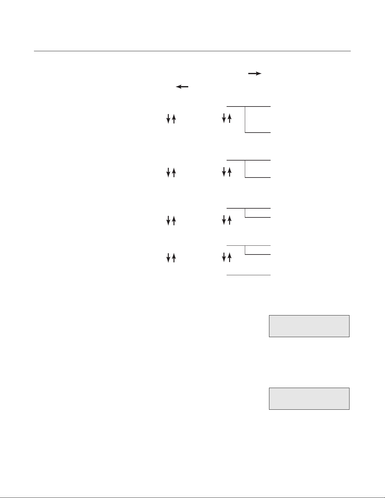
Instruction Manual
IM-106-5500, Original Issue
August 2005
Figure 4-3. Diagnostic Mode Tree
CCO 5500
Enter
Press Enter on Exit option
Detector Outputs Detector levels
D1, D2, E1, E2,
d1, d2, e1 & e2
Saturation count &
phase correction
Mod. Frequency Modulation frequency
of detector D1
Modulation frequency
of detector D2
Y Values & ppm Parameter Y values
Instantaneous gas
calculation (ppm)
Calibration Data Cal values
Rx temperature
Fault Condition Fault status
Detector Levels Detector levels from the detector are displayed here. D1 is the reference level
and should always be less than D2. The level of D2 should be between
10,000 and 20,000.
E2 and E1 are the detector levels with the gas
cell within the transmitter unit in the sight path,
and will be of the order of 1/2 of the D2 and D1
levels. Smoothed detector values may also be
displayed, these are noted as d1, d2, e1 and e2.
The first of these two parameters (Sat.#) indicates whether the detector
signals are saturating within the micro-processor (this value should always be
zero). If a number other than zero is displayed, it indicates saturation and the
detector gain should be adjusted. Refer to Section 3, Detector Levels.
Phase a is the phase time correction applied for
the calculation of the detector levels. This will
be between 0.1 and 5.9 milliseconds. This
value is calculated by the instrument and may
not be adjusted.
4 D2 = 18765E = 13453
D1 = 15464E = 10654
4 Sat. # = 00000
Phase a = 3.5msec
4-7
Page 58

CCO 5500
Instruction Manual
IM-106-5500, Original Issue
August 2005
Chopper Motor Frequency
The chopper blade should 'chop' the IR
radiation at a frequency of about 37 Hz. This
frequency is measured by the processor and
can be displayed from this option.
As the chopper blades interrupts the IR beam, the radiation is split into two half the time the blade obscures the beam and half the time the beam radiates
across the duct. The value of MARK/SPACE should be between 0.9 and 1.1
where:
MARK/SPACE = Time IR Beam Obscured/Time IR beam clear.
4 ModFreq = 37.4 Hz
Mark/Space = 0.984
YVals and Gas ppm A parameter 'Y' determines the calculation of the gas concentration - refer to
Section 1, Principles of Cross-Duct Gas Analyzers.
As a check on the program operation, this
parameter and the resulting raw gas
calculation, may be interrogated here.
The term Yx is the second averaging stack's
held value, and the term Y(60) is the 60-second
raw value from which all of the other averaging
stacks are calculated. These gas values
represent the raw gas data before averaging for the corresponding Y values.
Also displayed by pressing the arrow keys are the Z values. These are
adjusted Y values used to compensate for cross sensitivities in the
measurement range.
4 CO (0) = 3287ppm
CO (60) = 3289ppm
4 Y = 6060 Yx = 6058
Y (60) = 6058
Calibration Data The calibration factors, determined during the
calibration routine (Kcal), and the value
currently being used (Kwkg) can be examined
from this display. Should the two values be
different, this indicates a change in instrument temperature between the time
of calibration and the current temperature. Press one of the ARROW keys to
examine the temperature information.
Temperature has a small effect on the filter/gas
cell characteristics compensated for by the
instrument; temperature measurement is made
within the receiver.
4 Kwkg 9877
Kcal 9865
4 Rx ToF = 30.3
o
Kcal T
F = 30.1
4-8
Page 59

Instruction Manual
IM-106-5500, Original Issue
August 2005
CCO 5500
Fault Condition To display the current fault condition, press the
ENTER key while this is displayed. This display
mode is automatically selected by the
instrument, should a fault condition occur. The
following fault conditions are recognized by the instrument:
1. *ALL CLEAR* - No fault condition.
2. Det. Saturated - the detector level gain within either the receiver or the
signal processor is too high for the current duct conditions.
3. Low Det. Level - detector levels are too low (<3,000).
4. Mod. Freq. O.R. - chopper motor frequency is out of range (<30 Hz or
>45 Hz).
5. Reference Fail. - no reference signal from the transmitter unit.
6. Cal. Fact. O.R. - after the calibration routine, the calculated Set Cal
factor is out of range. Refer to Section 6, Troubleshooting.
By pressing the arrow key the previous fault
condition can be observed.
NOTE
If a fault condition exists, the minutes, hours and days averages will not be
updated. Refer to Section 6, Data Valid LED Out.
4 Diagnostic
Fault Condition
4 Previous fault
Det. Saturated
4-9
Page 60

Instruction Manual
IM-106-5500, Original Issue
CCO 5500
August 2005
Setup Mode All operating parameters - averaging times, output settings, normalization
parameters, path length, calibration, etc. - can be changed from this mode. To
prevent any unauthorized changes, the user must enter a four number code
before the mode can be entered.
NOTE
After this mode has been selected, the instrument will suspend its operation
and the Data Valid LED will extinguish. If no key is pressed within 5 seconds
after selection of this mode, the CCO 5500 will revert to the normal operating
mode.
Press the MODE key until the number 5 is displayed in the top left-hand
corner. After the security code has been correctly entered, there are 6
sub-modes of operation from which the set-up parameters may be changed
(Figure 4-4); these are:
1. Set Averages - The four averaging stack times (seconds, minutes, hours and days) may be set as required.
2. Configure O/P - Analog output setup - origin, units, span, rolling average
and fault condition.
3. Parameters - The following are set from this mode - security code,
identity number, path length, alarm level, cal factor and plant status.
4. Normalization - All normalization parameters may be set up from this
mode.
5. Reset Average - Selecting this sub-mode allows the four averaging
stacks to be reset.
6. Calibrate - The outputs of the detectors and the basic calibration of the
instrument can be set.
After the correct code has been entered, the user may access each of the six
sub-modes (listed above) by using the ARROW keys and pressing ENTER
when the required option is displayed.
Security Code Entry Once the display is as shown here, press the
ENTER key to gain access to the set-up mode.
The cursor will now flash over the first digit of
the presented code number; select the required
first digit with the arrow keys and press ENTER. Repeat this procedure for the
four numbers. If the code is correct after the ENTER key is pressed on the last
digit, then the sequence will be continued. If it is not correct, the instrument
will return to the operating mode - refer to Parameters for further details.
NOTE
The code number will be set to 0000 at the factory and should be changed by
the user from within the set-up mode.
5 SET UP MODE
Security # 0000
4-10
Page 61

Instruction Manual
IM-106-5500, Original Issue
August 2005
Figure 4-4. Set Up Mode Tree
CCO 5500
Enter
Press Enter on Exit option
Set Averages Seconds
Minutes
Hours
Days
Configure O/P Output
Average
Units
Span
Fault Condition
Set mA O/P
Parameters Security No.
Identity No.
Path Length
Alarm Source
Level
Cal. Factor
Plant Status
Normalization Temperature
Oxygen
Pressure
Water Vapor
10 to 60s @ 10s intervals
01 to 60m @ 01m intervals
01 to 24h @ 01h intervals
01 to 30d @ 01d intervals
0 or 4-20mA
Take average from secs, mins, hours or days stack
ppm - mg/m3 - mg/Nm3
0 to 9999 span (ppm or mg/m3 - depends on above)
Measured, zero mA, FS (20mA) or fix value
Set up current output levels
4-digit code
01 to 30 (unique number for serial data, I/Ps & O/Ps)
Gas path length in mm
Alarm from secs, mins, hours or days stack
0 to 9999 (ppm or mg/m3 - depends on units)
Determines basic calibration of the instrument
Contact, serial, temp., O2 or Det. level
Set up normalization I/P & std. levels for temp.
Set up normalization I/P & std. levels for O2
Set up normalization I/P & std. levels for pressure
Set up normalization I/P & std. levels for H2O
Reset Average Yes
Reset the four stack averages
No
Calibrate Set Detectors
Span Adjust
Calibrate
Detector D2
Adjust sensitivity
Conduct a basic calibration
Exit options not shown
Set Averages Four separate averages are calculated within the instrument. These are
defined in units of seconds, minutes, hours and days. Any of the four
averaging stacks can be used to provide the analog output of the instrument.
Each averaging time can be set within predefined limits.
4-11
Page 62

CCO 5500
Instruction Manual
IM-106-5500, Original Issue
August 2005
1. Press the ENTER key when this display
is shown; the display will now show one
of the averages. Use the ARROW keys to
select the average time that requires
changing, and press the ENTER key to change it. The value can now
be changed using the ARROW keys and input by pressing the ENTER
key.
2. Set the seconds averaging stack to the
required value. This is limited to within 10
to 60 seconds in10-second intervals.
3. Set the minutes averaging stack to the
required value. This is limited to within 1
to 60 minutes in 1-minute intervals.
4. Set the hours averaging stack to the
required value. This is limited to within 1
to 24 hours in 1-hour intervals.
5. Set the days averaging stack to the
required value. This is limited to within 1
to 30 days in 1-day intervals.
5 SET AVERAGES
5 SET AVERAGES
secs 60
5 SET AVERAGES
mins 60
5 SET AVERAGES
hours 24
5 SET AVERAGES
days 30
Configure O/P The analog current loop output is set up from
this mode. Press the ENTER key while this
display is shown to select it, then press the
ARROW keys to step through the available
options. Press the ENTER key to enter each option and change the displayed
parameter.
Base of Output
An origin of 0 or 4 mA can be set for the current
loop output. The ARROW keys will 'toggle'
between these two options. Press the ENTER
key to enter the new value.
Averaging Time of the Output
Any of the four averaging stacks (seconds,
minutes, hours and days) may be used for the
analog output. They are selected by the
ARROW keys and entered using the ENTER
key.
Output Units
The analog output can represent the gas
concentration in units of mg/m
ppm. The ARROW keys will 'toggle' between
these three options. Press the ENTER key to
enter the new value.
3
, mg/Nm3 or
5 CONFIGURE O/P
5 CONFIGURE O/P
OUTPUT = 4 to 20mA
5 CONFIGURE O/P
Average 0.1m
5 CONFIGURE O/P
Units mg/m3
4-12
Page 63

Instruction Manual
IM-106-5500, Original Issue
August 2005
CCO 5500
Output Span
Select the required span using the ARROW
keys for each digit. The ENTER key is pressed
to enter the value of each digit. The units will
be displayed in ppm, mg/m
depending on what has been selected beforehand. The current value will be
displayed for 1 second when this option is entered. The display then defaults
to zero; the span value must be re-entered for the unit to function correctly.
Fault Indication
Should a fault condition occur, the current
output of the instrument may be set to one of
the following options:
1. Set the output at 0 mA - ZERO.
2. Adjust the output to the calculated gas concentration even though a fault condition exists - MEAS.
3. Hold the last calculated gas concentration - HOLD.
4. Set the output to full scale (20 mA) - F.S.
One of these options can be selected by pressing the ARROW keys; when
the desired option is displayed press the ENTER key.
Set mA Output
3
or mg/Nm3,
5 CONFIGURE O/P
Span 0000mg/m3
5 CONFIGURE O/P
Fault cond ZERO
NOTE
This is set at the factory and should not be altered without due consideration.
From this option the current levels of the analog
output are set up. Press the ENTER key to
select it and the operator is prompted to set the
current levels at 0 to 20 mA.
When this is displayed, the current output should be set to 0mA as measured
with a calibrated current meter across the analog current loop terminals.
Nothing else should be connected to these terminals when the output is being
set up. The value is adjusted using the two arrow keys; the UP arrow will take
the current output up and the DOWN arrow will take it down. Press the
ENTER key when the correct output current is displayed on the ammeter.
NOTE
Zero mA should be set up no matter what has been selected as the base of
the current output. This is factory set by Rosemount Analytical.
6. In a similar manner to above, the current output level should now be set to 20 mA.
5 CONFIGURE O/P
Set Zero (007)
5 CONFIGURE O/P
Set Span (247)
4-13
Page 64

CCO 5500
Instruction Manual
IM-106-5500, Original Issue
August 2005
Parameters Select this option by pressing the ENTER key.
The ARROW keys will now display the available
options from within this sub-mode. When the
option that requires changing is displayed,
press the ENTER key. When all required changes have been made, select
the EXIT option and press ENTER.
Security Number
To prevent any unauthorized tampering with the
set up information, it is important that the
security code be changed from the factory
setting. Each digit is selected with the ENTER
key and changed with the ARROW keys.
NOTE
It is important to make a note of this number otherwise it will not be possible to
change the instrument set up.
Identity Number
If the system is being used as part of an integral
monitoring system and the serial input and
outputs are being used, the central processor
requires a 'Device Identity' to identify each
instrument. This number must be unique for each equipment item, and can be
set from 1 to 30 as required.
5 PARAMETERS
5 PARAMETERS
Security # 0000
5 PARAMETERS
Identity # 30
Measurement Path Length
NOTE
The current value entered for the path length will be displayed for 1 second,
then the display will default to zero. The path length must be re-entered for
the unit to calculate gas concentrations correctly.
The transmissivity of a sample of any gas
depends both on the concentration and on the
path length through which the radiation is
transmitted. Similarly, the output of the CCO
5500 analyzer gas monitor also depends on the path length of the flue gas
through which the radiation is transmitted.
The CCO 5500 analyzer is sensitive to the product of concentration x path
length and in order to obtain a true value of concentration of gas, it is
necessary to input the correct path length into the processor. This value is
then used to produce a final value of gas concentration.
NOTE
The path length entered must represent the length of the actual gas pass, not
the flange to flange dimension between the transmitter and receiver.
5 PARAMETERS
Pathlength 0000mm
4-14
Page 65

Instruction Manual
IM-106-5500, Original Issue
August 2005
CCO 5500
Alarm
A contact output is available to warn of a high
gas concentration. This contact output may be
triggered from any of the four averaging stacks.
Select the source with the ARROW key and
enter it with the ENTER key.
Select the units for the alarm - these may be
different to the units selected for the analog
output.
After the source has been selected, the
instrument requires a level that the output will
be triggered. Set the desired level with the
ARROW keys.
Cal Factor
NOTE
Do not enter this mode without first recording the original cal factor - this value
is displayed in Mode 4. Refer to Calibration Data. The Cal factor will be lost
when this menu option is entered.
During the calibration routine, the instrument
calculates a 'Cal Factor' which sets the basic
calibration of the instrument. This value may be
changed from this mode.
5 PARAMETERS
Alarm source 15m
5 PARAMETERS
Alarm mg/Nm3
5 PARAMETERS
Alarm 0000mg/Nm3
5 PARAMETERS
Cal Factor
NOTE
As this value controls the calibration of the instrument do not change it without
due consideration.
Plant Status Input
Used to determine whether the plant is operating under correct conditions. If it
is not, plant status will be OFF and the minutes, hours and days averaging
stacks will not be updated. If data is stored while the plant status is OFF
diluted overall readings will be registered.
There is a choice of three controls for plant
status, logic input, serial input and multiple
input, but only one can be used to control plant
status at any one time. The multiple input has
four options that may be configured for plant status; temperature threshold,
oxygen threshold, water vapor threshold, and logic input. Any or all of these
may be used to determine plant status.
Logic Input — If the PS1 and PS2 terminals are linked in the signal
processor the logic contact is made and the plant status is OFF. These
terminals may be linked manually during a plant shut down, or they may be
wired to a switch/contact outside the unit (e.g. a value that opens and
closes the duct). Select this option by pressing ENTER when the 'Plant
Status - Logic' screen is displayed.
5 PARAMETERS
Plant Status I/P
4-15
Page 66

CCO 5500
Instruction Manual
IM-106-5500, Original Issue
August 2005
Serial Input — If this option is selected the criteria controlling plant status
are transmitted via the serial data link. Select this option by pressing
ENTER when the 'Plant Status - Serial' screen is displayed.
Multiple — Four options are available here. Press ENTER when the 'Plant
Status - Multiple' screen is displayed. The first option is displayed Temperature. Use the arrow key to toggle YES or NO. NO will mean that
the temperature threshold is not used to determine plant status. If YES is
selected the display will enter the display below. Configure the instrument
for temperature threshold, press ENTER when correctly configured and
the display will move to the next option. Select YES or NO in a similar
manner to above. After the last option has been set (Logic Input) the
display will return to the 'PARAMETERS - Plant Status I/P' screen. Use the
down arrow to scroll down to EXIT and press ENTER. The plant status is
now fully configured.
Plant status will only be OFF if all options selected are registering plant
status OFF. If any one of them is not fulfilling plant status OFF conditions,
then the instrument will register plant status ON.
Temperature Threshold — A value is set here for the temperature
threshold. While the temperature (taken from the normalizing
temperature) is above the threshold value, plant status is ON. If the
temperature drops below the threshold, plant status is OFF and only
the seconds averaging stack will update.
Oxygen Threshold — Set and used in a similar manner to the
temperature threshold. However, if the normalizing oxygen level rises
above the threshold, plant status is OFF. For plant status ON, the
oxygen level must be below the threshold set.
Water Vapor — Set and used in a similar manner to the temperature
threshold. If the normalizing water vapor level falls below the threshold,
plant status is OFF. For plant status ON, the water vapor level must be
above the threshold set.
Logic Input — Select YES or NO and press ENTER. For plant status
to be ON the logic input (PS1 and PS2) must be open circuit; for plant
status to be OFF the logic input must be closed circuit. After this option
has been configured the menu will exit to 'Multiple'. Use the down
arrow to select EXIT and press ENTER.
4-16
Page 67
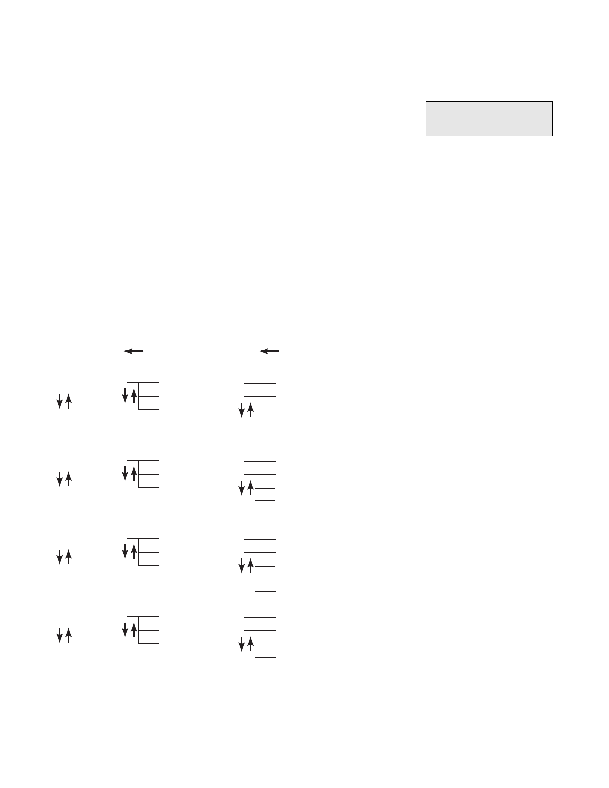
Instruction Manual
IM-106-5500, Original Issue
August 2005
CCO 5500
Normalization All of the normalization inputs and parameters
are set up from this mode. Press ENTER to
access the mode and the ARROW keys will
select which of the normalizing inputs are to be
changed, they are:
1. Temperature
2. Oxygen
3. Pressure
4. Water Vapor
After selecting the normalizing parameter, the user may set the standard
levels to which the measurement is to be normalized, and how the instrument
reads the value, i.e. fixed keypad input, 4-20 mA input, or on the serial data
line. Figure 4-5 illustrates the program tree for entering the normalization
parameters.
Figure 4-5. Normalization Options
Press Enter
on Exit option
Temperature Set std. levels
Set values
Exit
Press Enter
on Exit option
Value to which parameter is to be normalized
Analog I/P - use a 4-20mA input
Keypad I/P - set a fixed value from the keypad
Serial I/P - use the serial data line for this input
Exit
5 NORMALIZATION
Oxygen Set std. levels
Set values
Exit
Pressure Set std. levels
Set values
Exit
Water Vapor Set std. levels
Set values
Exit
Value to which parameter is to be normalized
Analog I/P - WET or DRY gas, use a 4-20mA input
Keypad I/P - set a fixed value from the keypad
Serial I/P - use the serial data line for this input
Exit
Value to which parameter is to be normalized
Analog I/P - use a 4-20mA input
Keypad I/P - set a fixed value from the keypad
Serial I/P - use the serial data line for this input
Exit
Value to which parameter is to be normalized
Keypad I/P - set a fixed value from the keypad
Serial I/P - use the serial data line for this input
Exit
4-17
Page 68

CCO 5500
Instruction Manual
IM-106-5500, Original Issue
August 2005
Setting the Normalizing Parameters
After selecting the parameter to be set up, the ARROW keys will select
between entering the standard levels and how the normalization data is to be
brought into the instrument.
Set Standard Levels
Each normalizing parameter normalizes the
measured gas concentration to standard
conditions of temperature, oxygen, pressure
and water vapor. These levels are set from
within this option. Use the ARROW keys to change each displayed
normalizing standard value.
Set Values
The normalizing data can be brought into the instrument in one of 3 ways:
1. By entering a fixed value via the keypad.
This is suitable where the value is stable
to about ±5%.
2. If an INPUT UNIT is being used, all normalizing data can be transmitted via the serial data line.
3. Use the 4-20 mA inputs within the processor to receive a measurement transducer data. The values at 4 mA and at 20 mA will be requested should this option be selected.
5 TEMP DegF
std level 000
5 TEMP DegF
Keypad Input
5 TEMP
Serial Input
5 TEMP DegF
Analog Input
With an integrated system the lead analyzer should have its normalizing
parameters set to 4-20 mA inputs. Select the above analog screen and enter
the values required for the 4 mA and 20 mA inputs. For the oxygen input the
value must be selected as a wet or dry gas measurement. This is explained in
more detail below. All the other analyzers in an integrated system must be set
to the serial inputs and the normalization parameters will be transmitted down
the serial data highway.
Temperature An analog input should always be used for temperature correction - this
ensures that the flue gas temperature is being measured continuously and
accurately. Connect the analog output of the temperature transducer into the
CCO 5500 analyzer and select the analog input option. This value is used to
normalize the gas concentration measurement and to correct for the effects of
temperature on the IR absorption spectrum.
If a fixed value input is used then at flue gas temperatures higher than 572
o
(300
C) the compensation algorithm will become less precise and instrument
accuracy will deteriorate accordingly. This is not recommended.
NOTE
If normalization is not required, the instrument must hold the temperature of
the gas in the duct - analog input.
4-18
o
F
Page 69

Instruction Manual
IM-106-5500, Original Issue
August 2005
CCO 5500
Oxygen To correct the data to standard levels of oxygen, an estimate of the oxygen at
the point of measurement is required. If the oxygen level is being continuously
measured, connect the analog output of the oxygen analyzer into the CCO
5500 analyzer and select the analog input in the normalization menu. This
input must be defined as either WET or DRY, depending on how the
measurement is made. After the measurement has been defined as wet or
dry, the analog input values need defining; set the 4 mA and 20 mA values. If
the oxygen level is relatively constant through all firing conditions, then a fixed
(keypad) input may be used.
NOTE
If normalization is not required, the instrument must have the normalizing
parameters for oxygen set to 0% (standard level and keypad input).
With an integrated system the oxygen data can be taken to the CCO 5500 via
the serial data line.
Pressure To correct the data to a standard pressure - normally 14.65 psi (101 kPa), the
pressure at the point of measurement needs to be determined. If the flue
pressure is relatively constant through all firing conditions, then a fixed input
may be used. If the pressure is not constant, it should be measured and
brought into the CCO 5500 via the 4-20 mA input within the processor.
NOTE
If normalization is not required, the CCO 5500 must have the normalizing
parameters for pressure set to 101 kPa (standard level and keypad input).
With an integrated system the pressure data can be taken to the CCO 5500
via the serial data line.
Water Vapor An 'across the duct' monitor measures the gas concentration under wet
conditions, that is, unlike a sampling system, the gas has not been
preconditioned in any way before the measurement is made.
To normalize it to dry conditions, when the water vapor present is of a known
and relatively fixed level, set the standard level to DRY and use a fixed value
in the keypad option representing the expected water vapor produced for the
fuel type. If the measurement is not to be normalized for water vapor, set the
standard level to WET.
With an integrated system the water vapor data can be taken to the CCO
5500 via the serial data line.
Reset Averages NOTE
The rolling average data will be cleared from memory - consider carefully
before using this option.
The average values that are currently held in
the four averaging stacks can be reset using
this option; this will erase the current average
that is held in all of the averaging stacks. Select
this option by pressing the ENTER key and using the ARROW keys.
Confirmation is requested before the averages are reset.
5 RESET AVERAGES
4-19
Page 70

CCO 5500
Instruction Manual
IM-106-5500, Original Issue
August 2005
NOTE
If this option is selected, all data in the averaging stacks is reset and the data
for as much as the last 30 days will be lost.
Calibrate From this option the two detector levels may be
displayed and a basic calibration conducted.
While in this mode the gas cell is not moved;
this gives an immediate response for setting up
the detector levels. The basic calibration of the instrument is set by a 'CAL
FACTOR' that is calculated during a calibration routine. Press the ENTER key
while this is displayed and the following options are available:
Set Detectors
Both the D1 and D2 levels can be displayed;
saturation counts are also displayed. To give an
immediate response to any alterations that are
required, the filters and gas cells are not moved
during this operation.
Refer to Section 3, Configuration and Startup and, Section 4, Diagnostic
Mode for a discussion of these levels - detector level and saturation count.
Span Adjust
NOTE
The SPAN FACTOR is initially set at the factory; do not adjust it unless the
instrument sensitivity is suspected. In any case it is recommended that before
adjustments are made the original value is recorded.
5 CALIBRATE
5 D2 = 10534 # = 00000
D1 = 15000 # = 00000
Instrument sensitivity can be adjusted if a
known concentration of measurement gas
exists between the transmitter and receiver
units, and instrument sensitivity is suspected. If
a problem arises with this consult Rosemount Analytical.
The SPAN FACTOR may need adjusting if new gas cells or filters have been
fitted. Refer to Span Adjust.
5 Val = 250 –> 250ppm
Span Factor 1000
CHECK CELL MODE This mode is for use with a Rosemount Analytical check cell. It verifies the
calibration and operation of the analyzer. For details of its use refer to “Notes
for Using a Rosemount Analytical Check Cell” on page 4-21.
Press enter on viewing this display if the check
cell mode is required. Use the arrow keys to
toggle the display to YES and press enter
again.
The check cell mode is now selected. Note that
the display will default back to Mode 1 if YES is
not selected within 5 seconds.
6 Ch’k Cell Mode
6 Ch’k Cell Mode
YES
4-20
Page 71

Instruction Manual
IM-106-5500, Original Issue
August 2005
CCO 5500
NORMAL SHUTDOWN PROCEDURE
ROUTINE CHECKS
Notes for Using a Rosemount Analytical Check Cell
The check cell must not be inserted before this
screen is accessed. Refer to Notes for Using a
Rosemount Analytical Check Cell.
The system should not need shutting down unless maintenance is being
carried out. In this case, power down the power supply (and thus the signal
processor and analyzer heads). Close the manually operated isolating valves
on the analyzer heads and proceed with service. When satisfactorily
completed, open the valves and power up the system. The system may need
a calibration performed, depending on the type of maintenance carried out.
For details refer to Section 6, Troubleshooting.
The check cell and holder are optional items available from Rosemount
Analytical. The Rosemount Analytical check cell has been designed to verify
the reading of Rosemount Analytical cross duct analyzers. When placed
within the measurement path a known increase in gas concentration can be
generated.
NOTE
The check cell should be placed at the receiver side.
Measurement Conditions
6 CO = 0060ppm
CO = 0121ppm.m
For absolute verification it is necessary to conduct a check on the instrument
when there is no measurement gas present. If a background concentration of
measurement gas is present, an increase will still be generated, but the net
effect will be complex.
Mode 6
This mode of the analyzer is used in conjunction with a check cell to verify the
calibration and operation of the monitor.
The ideal time to perform a check cell test is with the plant off, auto zero
condition on, and the analyzer well stabilized at zero. Do not insert the check
cell in any other mode than Mode 6.
The rolling averages of the analyzer will not update during use of Mode 6 - to
prevent false readings being recorded - the check cell mode cannot be
operated from the IEM system.
Check Cell Procedure
1. Enter Mode 6 on the signal processor before inserting the check cell
into the analyzer. Press enter when Mode 6 is displayed.
2. Use an arrow key to toggle from NO to YES and press enter to access the check cell function. If this is not selected within 5 seconds the instrument returns to the normal operating mode.
3. When this screen is seen the check cell must be inserted observing the procedure outlined below.
4. Remove the two screws retaining the cover on the check cell holder (Figure 4-5).
6 Ch’k Cell Mode
YES
4-21
Page 72

CCO 5500
Figure 4-6. Check Cell Holder
Instruction Manual
IM-106-5500, Original Issue
August 2005
Check Cell
Figure 4-7. Check Cell
Check Cell Holder
5. Insert the check cell into the check cell holder and replace and tighten the screws. The cell can be inserted in either direction. Refer to Figure 4-7.
Gas Cell Winow
6. Introducing the check cell may cause an initial major disturbance to the instrument operation.
7. Wait for the instrument reading to settle - 5 to 10 minutes - and record the gas measurement with the cell in position.
8. Remove the check cell and wait for the analyzer to return to zero (another 5 to 10 minutes).
9. Replace the cover on the check cell holder and press the mode key on the signal processor. The instrument now returns to operation mode.
10. This test can be done with the plant on line, but any pollutant gas present (also it will probably be residing at a different temperature) will interfere with the check cell value.
Receiver
4-22
NOTE
Do not insert the check cell in any other mode as this will influence the
recorded rolling averages.
The calibration of the CCO 5500 analyzers is fixed at the point of
manufacture. If gross errors exist this could suggest an instrument
malfunction. If minor errors are observed, please check the procedure and if
necessary return the gas cell for re-certification.
Page 73

Instruction Manual
IM-106-5500, Original Issue
August 2005
CCO 5500
Alarms and Emergency Conditions
Emergency Shutdown Procedure
The alarm thresholds for the system are set as described in the normal
operating mode. When an alarm condition is obtained the red LED on the
signal processor will light up. This will go out when the alarm condition has
cleared. If the analyzers are linked to the Integrated Emission Monitoring
package that remotely monitors the system, the alarm will be displayed on the
IEM system monitor. When the condition has cleared the fact that an alarm
condition occurred will be recorded by the software. The 4 to 20 mA output
from the analyzer will also alter according to the pollution levels detected.
The same as normal shutdown - remove power from the power supply and
the whole system will close down. Close the isolating valves if required and
stop the flow of air to air purges.
Isolation Procedure Shut off power to the power supply. Shut off compressed air to the air purges
and shut the isolating valves.
Interface with Integrated Emissions Monitoring System
If the system interfaces with a Rosemount Analytical IEM software package
via a serial data line, central control unit (CCU) and pc, then details of
configuration of this system are to be found in the operating manuals
OPS.087 (Communication Equipment) and OPS.016 (IEM Software).
4-23
Page 74

CCO 5500
Instruction Manual
IM-106-5500, Original Issue
August 2005
4-24
Page 75

Instruction Manual
IM-106-5500, Original Issue
August 2005
Section 5 Maintenance
Routine (Preventive) Maintenance . . . . . . . . . . . . . . . . . . page 5-1
Span Factor Adjustment . . . . . . . . . . . . . . . . . . . . . . . . . . page 5-3
Install all protective equipment covers and safety ground leads after equipment repair or
service. Failure to install covers and ground leads could result in serious injury or death.
CCO 5500
ROUTINE (PREVENTIVE) MAINTENANCE
The equipment is designed to keep levels of maintenance to an absolute
minimum.
Cleaning Windows It is important that the optical windows of both transmitter and receiver are
kept reasonably clean and any mounting tubes free from build-up of dust and
fly ash. We recommend that the windows are cleaned every six months, or
more often for dirty processes, by removing the transmitter and receiver from
their air purges and wiping their windows with a soft dry cloth.
Great care must be taken when removing the CCO 5500 from a positive pressure stack or
duct. The source may be very hot, and there may be dangerous vapors present. Observe all
required safety practices.
Replacement of the Heater Element
The heater element does have a limited life and at some stage will have to be
replaced. The unit has been designed to give a minimum of two years
continuous operation and when replacement does become necessary it can
be replaced on site.
http://www.raihome.com
Page 76

CCO 5500
Instruction Manual
IM-106-5500, Original Issue
August 2005
To replace an element proceed as follows:
1. Switch OFF power.
2. Remove the rear cover plate from the transmitter by removing the four retaining screws. Note that these screws are not captive.
3. Carefully remove the PCB now revealed by unscrewing the three retaining screws.
4. Disconnect the two wires from the terminals at the rear of the heater assembly by removing the two M3 nuts.
5. Remove the heater assembly by unscrewing the three screws. These are captive screws and cannot be removed completely. The heater assembly may then be withdrawn from the transmitter and discarded.
6. Refit a replacement unit by reversing the above procedure.
7. After completion, switch ON the power and allow fifteen minutes for the heater to attain temperature after which the equipment will start to calculate the gas levels.
Replacement of Chopper Motor Assembly
Replacement of Gas Cells
1. Turn the power OFF and remove the transmitter from its air purge.
2. Remove the four screws holding the transmitter front flange in position and remove the front flange.
3. Turn the three brass extended head screws counterclockwise (unscrew) to loosen assembly.
4. Carefully lift out the assembly and remove the center plate from the transmitter body.
5. De-solder the red and black wires attached to the chopper motor.
6. Remove the three screws holding the chopper motor to the center plate.
7. Replace the chopper motor and reverse the above procedure.
8. Turn the power ON and check the chopper motor frequency by viewing in Mode 4 - Diagnostics. Adjust using the trim potentiometer as described in “Transmitter Adjustments” on page 3-7.
Transmitter
1. Turn the power OFF and remove the transmitter from its air purge.
2. Remove the four screws holding the transmitter front flange in position and remove the front flange.
3. Turn the three brass extended head screws counterclockwise (unscrew) to loosen assembly.
4. Carefully lift out the assembly and ease the PCB off its supports.
5. Unscrew the M3 x 6 slotted screw (or grub screw on some models) at the end of the gas cell assembly.
6. Pry the gas cell off the stepper motor shaft.
7. Place the new gas cell in position and reverse the above process.
8. Turn ON the power and recalibrate. Refer to Section 4, Calibrate.
5-2
Page 77

Instruction Manual
IM-106-5500, Original Issue
August 2005
Receiver
1. Turn the power OFF and remove the receiver from its air purge.
2. Remove the receiver cover from the front flange.
3. Remove the four screws holding side detector PCB to the main body of the receiver (M4 x 16 screws).
4. Completely remove the four M6 bolts from the end detector PCB.
5. Slide out the gas cell assembly.
6. Replace the gas cell, ensuring that the same orientation is kept - the notch in the gas cell assembly should be facing away from the side on which the side detector PCB fits.
7. Reverse the above process being careful not to overtighten the four bolts (if these are too tight the gas cell may fracture).
8. Turn the power ON and recalibrate. Refer to Section 4, Calibrate.
CCO 5500
Electronics The electronics require no routine maintenance. They are all solid state and
undergo a rigorous factory burn-in procedure. If there is any doubt about the
equipment performance the signal processor may be interrogated from the
keypad to determine whether or not the equipment is functioning normally.
Refer to Section 6, Troubleshooting.
SPAN FACTOR ADJUSTMENT
The span factor does not normally need adjusting. However, if any of the
following changes have taken place it may be necessary to adjust it:
1. Gas cell changed either in the receiver or the transmitter.
2. Interference filter changed in the receiver.
The procedure for changing the span factor in these cases is as follows:
1. Set the span factor to 1000 in Mode 5.
2. Calibrate the analyzer under zero conditions.
3. Obtain a check cell reading in Mode 6 [note that the check cell is defined
at a temperature of 68
4. Set the temperature input in Mode 5 normalization to Keypad 68
o
(20
C).
5. Enter the pathlength in Mode 5. Note that the check cell reading must
be less than 999 ppm.m; if it is greater than this, use a larger pathlength
to reduce the effective ppm.m value of the check cell (i.e. select the
pathlength such that ppm.m/pathlength <999).
6. In Mode 5 under the span factor menu enter the value read for the check cell in Mode 6. Note that if this value exceeded 999 ppm divide by the pathlength entered above.
7. Press Enter and wait for the second reading to appear under the span factor option. This should read the same as the value entered above.
8. Using the up and down arrow keys adjust the span factor until the second reading agrees with the certified check cell value (divided by the pathlength if appropriate).
9. Note the span factor value and press Enter.
10. Confirm the span factor is set by entering Mode 2 and checking span factor under the parameters menu option.
o
F (20oC) and a pathlength of 3.28 ft (1 m)].
o
F
5-3
Page 78

CCO 5500
Instruction Manual
IM-106-5500, Original Issue
August 2005
An example of resetting the span factor is outlined below:
• Certified check cell of 2880 ppm is inserted into the check cell holder
with the analyzer in Mode 6 and a reading taken. This reading is 3240.
• Due to the value of the check cell exceeding 999 ppm a suitable
pathlength needs to be used to reduce the effective value of the check
cell. In this case a pathlength of 4 m is chosen, thus the effective value
of the check cell in 720 ppm (2880/4).
• However, in Mode 6 it reads higher (3240); this value is effectively 810
ppm at a 4 m pathlength.
• 810 is keyed in as the first value in the span factor option.
• The span factor is then adjusted until the second value reads 720.
• Now press Enter to set the span factor.
5-4
Page 79

Instruction Manual
IM-106-5500, Original Issue
August 2005
Section 6 Troubleshooting
Fault Finding with the Keypad . . . . . . . . . . . . . . . . . . . . . . page 6-1
Troubleshooting Tables . . . . . . . . . . . . . . . . . . . . . . . . . . . page 6-2
Component Tests . . . . . . . . . . . . . . . . . . . . . . . . . . . . . . . . page 6-8
LED Indications . . . . . . . . . . . . . . . . . . . . . . . . . . . . . . . . . . page 6-8
Test Points . . . . . . . . . . . . . . . . . . . . . . . . . . . . . . . . . . . . . . page 6-9
FAULT FINDING WITH THE KEYPAD
Install all protective equipment cov ers and saf ety g round leads after troubleshooting. F ailure
to install covers and ground leads could result in serious injury or death.
CCO 5500
Should a fault occur the display switches from its current mode of operation to
the diagnostic mode and displays the current fault condition - refer to Data
Valid LED Out. If this fault clears, the display will stay in the diagnostic mode
and display the 'All Clear'.
Enter the diagnostic mode from the keypad of the instrument; this can be
done at any time without interrupting or disturbing the analog outputs of the
equipment.
As an initial guide to equipment performance, typical values for instrument
operation are given below:
D2
min
CCO 5500 3000 20,000 3000 20,000 2000 2900
where:
• Modulation Frequency = 30 to 45 Hz
• Mark/Space Ratio = 0.9 to 1.1
• Saturation Count = 50 maximum for all analyzers
Should the values be outside of the above ranges, the Data valid LED will
extinguish, and the fault condition be displayed.
D2
max
D1
min
D1
max
Set Cal
min
Set Cal
max
Data Valid LED Out If one or more fault conditions occur, the data valid LED on the front panel will
extinguish, the data valid relay will operate and the instrument will
automatically enter the diagnostic mode to display the fault condition.
6-1
Page 80

CCO 5500
Table 6-1. Fault Conditions
Instruction Manual
IM-106-5500, Original Issue
August 2005
The following fault conditions are recognized by the instrument.
Detector signals saturated (Sat# over 50)
Possible Causes
Incorrect detector gain adjustment.
Instrument condition during high opacity conditions which have now cleared.
Low detector levels (D1 < 3,000)
Possible Causes
High opacity in duct.
Dirty windows.
Incorrect detector gain adjustment.
Heater cartridge failure.
Cal factor out of range
Possible Causes
Calibration conducted during unstable duct conditions.
Poor alignment.
Incorrect detector gain adjustment.
Modulation frequency is below 30 Hz or above 45 Hz
Possible Causes
Poor supply voltage.
Faulty chopper motor.
Incorrect setting within transmitter.
Reference signal failure
Possible Causes
Chopper motor failure.
TROUBLESHOOTING TABLES
NOTE
If a fault condition is recognized by the instrument the minutes, hours and
days averages will not be updated.
Further troubleshooting information is provided in Table 6-2 and Table 6-3.
The troubleshooting tables provide fault diagnosis, possible causes and the
appropriate actions, if an instrument fault is suspected. Note the symptoms
and when the fault has occurred and refer to the appropriate tables.
NOTE
Be sure to use the tables from the top down and pay particular attention to the
'proceed to next TEST or CAUSE' information.
If the fault cannot be rectified by the customer then the tables should indicate
which of the four units are faulty:
• power supply
• signal processor
• transmitter
• receiver
The faulty unit can then be returned to Rosemount Analytical for repair.
6-2
Page 81

Instruction Manual
IM-106-5500, Original Issue
August 2005
CCO 5500
Table 6-2. Configuration Problems
No display on signal processor
Possible Cause Tes t Result Action
Mains input failure Check 110/220V
Power supply failure Check power rail LEDs
Connection Problem Check wiring between
Signal processor
failure
Display nonsense on signal processor
Possible Cause Tes t Result Action
Micro-processor fault Reset by interrupting
Program
corruption/faulty micro
PCB
selection switch in
power supply
Check power indication
LED in power supply
Check fuse in power
supply
in signal processor
Check fuse in signal
processor
signal processor &
power supply
Check ribbon cable
connections in signal
processor
- - Contact your
mains supply
- - Contact your
Setting correct Proceed to next test
Setting incorrect Change setting &
LED illuminated Mains OK - proceed to
LED not
illuminated
Fuse OK Proceed to next
Fuse blown Replace fuse
All LEDs
illuminated
LEDs not
illuminated
Fuse OK Proceed to next
Fuse blown Replace fuse
Wiring OK Proceed to next test
Incorrect wiring Correct wiring
Connections OK Proceed to next
Connections
loose
Fault clears No further action
Fault continues Proceed to next
proceed to next test
next possible cause
Proceed to next test
possible cause
Supplies OK proceed to next
possible cause
Proceed to next test
possible cause
possible cause
Secure connections
Rosemount Analytical
supplier
possible cause
Rosemount Analytical
supplier
6-3
Page 82

CCO 5500
Instruction Manual
IM-106-5500, Original Issue
Display message ‘Waiting for Reference’
Possible Cause Tes t Result Action
Reference wave
failure
Chopper motor failure
in transmitter
Data valid LED not illuminated
Possible Cause Tes t Result Action
Analyzer fault
condition
Reference failure
Possible Cause Tes t Result Action
Reference wave
failure
Checking wiring
between power supply
and signal processor
and also between
power supply and
transmitter
Check ref. wave in
power supply - use
oscilloscope @
terminals 4 and 5
Check ref. wave in
signal processor - use
oscilloscope @
terminals 2 and 5
Check if chopper blade
is rotating
Replace chopper
motor
Interrogate fault status
in Mode 4
Proceed as for
symptom 3
Wiring OK Proceed to next test
Wiring incorrect Correct wiring
37 Hz square
wave approx.
12V - OK
See above - not OKProceed to next
37 Hz square
wave approx.
12V - OK
See above - not OKCheck and rectify
No Proceed to next test
Yes Contact your
Fault clears No further action
Fault continues Contact your
*All Clear* Contact your
Fault condition
identified
Fault clears No further action
Fault continues Contact your
Proceed to next test
possible cause
Contact your
Rosemount Analytical
supplier
wiring/continuity
between power supply
and signal processor
Rosemount Analytical
supplier
Rosemount Analytical
supplier
Rosemount Analytical
supplier
Proceed to relevant
symptom
Rosemount Analytical
supplier
August 2005
6-4
Page 83

Instruction Manual
IM-106-5500, Original Issue
August 2005
CCO 5500
Low detector level
Possible Cause Tes t Result Action
Incorrect wiring Checking wiring Fault clears No further action
Fault continues Proceed to next
Dirty windows or
obstructed sight path
Misalignment Realign Rx and Tx
Incorrect gain settings Adjust gains in signal
Transmitter failure Check heater cartridge Cartridge open
Transmitter gas cell
drive failure
Detector saturated
Possible Cause Tes t Result Action
Incorrect gain settings Adjust gain settings in
Check and clean the
Rx and Tx windows clear sight path
between Rx and Tx
units
processor and/or Rx
Check drive LED in
signal processor
Check gas cell/filter
drive
signal processor
and/or Rx
Monitor detector levels
from Rx
Detector levels in
range
Fault continues Proceed to next
Detector levels in
range
Fault continues Proceed to next
Detector levels in
range
Fault continues Proceed to next
circuit
Cartridge OK Proceed to next
LED flashing Proceed to next test
LED not flashing Contact your
No movement Contact your
Movement Contact your
Saturation clears No further action
Fault continues Proceed to next test
Signal OK Contact your
Signal faulty Contact your
possible cause
No further action
possible cause
No further action
possible cause
No further action
possible cause
Replace heater
cartridge
possible cause
Rosemount Analytical
supplier
Rosemount Analytical
supplier
Rosemount Analytical
supplier
Rosemount Analytical
supplier
Rosemount Analytical
supplier
6-5
Page 84

CCO 5500
Instruction Manual
IM-106-5500, Original Issue
Modulation frequency out of range
Possible Cause Tes t Result Action
Chopper motor speed
out of range
Set Call out of range
Possible Cause Tes t Result Action
Calibrated with
incorrect target value
or under fluctuating
gas level
Poor alignment /
window contamination / path obscured
Tx gas cell drive failure Proceed as for low
D2 detector/circuit
failure
Transmitter gas cell
failure
Receiver gas cell
failure
Adjust chopper motor
speed
Monitor ref. waveform
across 10 and 11 in
power supply using
oscilloscope
Calibrate with correct
target value
Proceed as for low
detector level
detector level
Check D2 signal level OK Proceed to next
Monitor D2 signal from RxOK Contact your
Replace Tx gas cell Cal factor in range No further action
Replace Rx gas cell Cal factor in range No further action
Mod. Frequency
in range
Unable to adjust Proceed to next test
30 - 45 Hz
waveform OK
<30 or >45 Hz waveform
incorrect
Cal factor in range No further action
Cal factor out of
range
Cal factor in range No further action
Cal factor out of
range
Cal factor in range No further action
Cal factor out of
range
Not OK Proceed to next test
Not OK Contact your
Cal factor out of
range
Cal factor out of
range
No further action
Contact your
Rosemount Analytical
supplier
Contact your
Rosemount Analytical
supplier
Proceed to next
possible cause
Proceed to next
possible cause
Proceed to next
possible cause
possible cause
Rosemount Analytical
supplier
Rosemount Analytical
supplier
Proceed to the next
possible cause
Contact your
Rosemount Analytical
supplier
August 2005
6-6
Page 85

Instruction Manual
IM-106-5500, Original Issue
August 2005
Table 6-3. Operational Problems
CCO 5500
Output reading permanently zero or full scale
Possible Cause Tes t Result Action
Incorrect normalizing
parameter setting
Incorrect calibration
(Set Cal value) zero
gas level
Detector levels low or
saturated
Output circuitry failure Enter setup mode
Averages not updated
Possible Cause Tes t Result Action
Fault condition exists Enter diagnostic mode
Plant status contact in
signal processor has
been made
Enter parameter mode
and ensure all
parameters are as
required
Enter diagnostic mode
and observe the Y (60)
figure
Enter diagnostic mode
and check the detector
levels and saturation
count
(configure output and
attempt to set zero and
span
and check fault
condition
Check plant status
input LED in signal
processor
Parameters
correct
Parameters
incorrect
1800 <Y <2010 Instrument OK - true
Y <1800 Proceed to next
Detector levels OKProceed to next
Detector levels
out of tolerance
Output responds
correctly
Output does not
respond correctly
Fault condition
exists
No fault condition Proceed to next
LED off Operation correct -
LED on Plant status in use -
Proceed to next
possible cause
Enter correct
parameters
level of gas in duct
(output permanently
zero)
possible cause
possible cause
Reconfigure the
instrument and
consult the
fault-finding table
again
Reconfigure the
instrument and
consult the
fault-finding table
again
Replace signal
processor
Refer to Section 4,
Fault Condition
possible cause
stable gas level
instrument will not
update until plant on
6-7
Page 86

Instruction Manual
IM-106-5500, Original Issue
CCO 5500
August 2005
COMPONENT TESTS Some instrument components/operation can be verified as follows:
Heater Cartridge Perform the steps for Section 5, Replacement of the Heater Element within
the transmitter up to step 4. Remove one lead from the heater cartridge and
measure the resistance across the two cartridge terminals. It should be about
3.5S. If the circuit is open the heater cartridge needs replacing.
Chopper Motor 1. Turn the power ON.
2. Observe the chopper motor and blade between the lens and heater cartridge. If the blade is spinning, the chopper motor is OK.
3. If the blade is not spinning, the supply to the chopper motor can be
measured at the test points M+ and M– on the board to the front of the
unit (nearest the lens) - it should be about 1V DC. If it is, the chopper
motor assembly requires changing; if it is, not the transmitter unit is
faulty.
LED INDICATIONS If instrument malfunction is suspected, there are LEDs within the instrument
indicating various power rails and equipment operations.
Signal Processor LEDs
5V, -15, +15 Situated top/left of processor. Should all be
M-DIR Should operate approximately every 4
SOL_MDRV Supply to the solenoid that drives the filter into
+V1, -V1 and +12V Middle bottom left of board. All should be ON.
+12V Bottom left of board. Should be ON. Indication
PS Bottom left of board. In normal operation, this
Receiver LEDs
+V and -V These LEDs should be ON indicating that the
Transmitter LEDs
+V and -V These LEDs should be ON indicating that the
Power Supply LED
+12V This LED should be ON indicating that the
ON, indicating that the power supplies to the
instrument are functioning correctly.
seconds.
the optical path within the receiver pulses
every time the M-DIR changes (approximately
every 2 seconds).
Power supplies to the isolated analog current
output.
of the isolated supply for the plant status input.
LED should be OFF. During plant-off periods,
however, if the plant status input is being used,
this LED will illuminate and the rolling averages
not updated.
power supplies within the unit are functioning
correctly.
power supplies within the unit are functioning
correctly.
power supply unit is functioning correctly. This
LED will extinguish should the supply voltage
drop from 12 to 11V.
6-8
Page 87

Instruction Manual
IM-106-5500, Original Issue
August 2005
CCO 5500
TEST POINTS If further checks on instrument operation are required, there are various test
points within the instrument. Many of these are simple DC voltages and so
may be checked using a voltmeter set to DC volts, otherwise may be
investigated using an oscilloscope:
Signal processor
T1 D1 signal from receiver head with some
T2 D1 signal after amplification in processor.
T3 D1 output to the A/D converter within the
T4 As T1 but for D2 signal.
T5 As T2 but for D2 signal.
T6 As T3 but for D2 signal.
T7 Receiver ambient temperature to the A/D
T8 Normalizing input for pressure, before A/D
T9 As T8 except oxygen.
T10 As T8 except temperature.
+5 and 0V Supply rails for the micro-processor. DC
12V Supply rail for the plant status input.
+15V, -15V and 0VA Supply rails for the analog current output.
VIN Output from the D/A converter. 0 to 2.5V
-15V1, 0V and +15V1 Isolated supply for the analog current output.
0VB and +12VB Isolated supply for the plant status input.
F Reference wave from the transmitter unit (via
Power Supply
0V and +12V Power supply for the instrument.
Receiver
0V 0V for the receiver.
T1 Detector output without conditioning.
T2 Detector output after first stage of gain.
T3 Detector output after both stages of gain.
Transmitter
S- 0V supply to the heater cartridge.
S+ 12V supply to the heater cartridge.
M+ and M- Supply to the chopper motor (+1V DC).
T3 Reference wave.
T4 Reference wave.
conditioning in the processor, smoothed by a
factor of divide by 10. Flattened saw-tooth, 32
to 45 Hz (modulation frequency) 1V pk-pk
(maximum), centred on 0V. 0V for T1 to T6
may be taken from 0V test point, top left of
board. Test-points T1 to T6 are to be found in
the center of the board.
Flattened saw-tooth, 32 to 45 Hz, 3.5V pk-pk
(maximum), centered on 0V. Amplitude may be
varied by a trim pot. Refer to Section 4,
Detector Levels.
micro-processor, offset by 2.5V. Flattened
saw-tooth, 32 to 45 Hz, 3.5V pk-pk (maximum),
centered on 2.5V.
converter with the micro-processor - 1mV
represents 33.8
converter 0.8 to 4.0V = 4 to 20 mA.
voltage.
represents 0 to 20 mA (4 mA at 0.V).
the power supply). Square wave, 30 top 45 Hz,
5V pk-pk, centered on 2.5V.
o
F (1oC).
6-9
Page 88

CCO 5500
Instruction Manual
IM-106-5500, Original Issue
August 2005
6-10
Page 89

Instruction Manual
IM-106-5500, Original Issue
August 2005
Section 7 Returning Material
If factory repair of defective equipment is required, proceed as follows:
1. Secure a return authorization number from a Rosemount Analytical
sales office or representative before returning the equipment.
Equipment must be returned with complete identification in accordance
with Rosemount Analytical instructions or it will not be accepted.
In no event will Emerson Process Management be responsible for
equipment returned without proper authorization and identification.
2. Carefully pack defective unit in a sturdy box with sufficient shock absorbing material to ensure that no additional damage will occur during shipping.
3. In a cover letter, describe completely: a. The symptoms from which it was determined that the equipment is
faulty.
b. The environment in which the equipment has been operating
(housing, weather, vibration, dust, etc.).
c. Site from which equipment was removed.
d. Whether warranty or nonwarranty service is requested.
e. Complete shipping instructions for return of equipment.
f. Reference the return authorization number.
4. Enclose a cover letter and purchase order and ship the defective equipment according to instructions provided in Rosemount Analytical Return Authorization, prepaid, to:
CCO 5500
Rosemount Analytical Inc.
RMR Department
Daniel Headquarters
11100 Britmore Park Drive
Houston, TX 77041
If warranty service is requested, the defective unit will be carefully inspected
and tested at the factory. If failure was due to conditions listed in the standard
Rosemount Analytical warranty, the defective unit will be repaired or replaced
at Rosemount Analytical's option, and an operating unit will be returned to the
customer in accordance with shipping instructions furnished in the cover
letter.
For equipment no longer under warranty, the equipment will be repaired at the
factory and returned as directed by the purchase order and shipping
instructions.
http://www.raihome.com
Page 90

Instruction Manual
IM-106-5500, Original Issue
August 2005
CCO 5500
7-2
Page 91

Instruction Manual
IM-106-5500, Original Issue
August 2005
Section 8 Replacement Parts
Recommended Spare Parts . . . . . . . . . . . . . . . . . . . . . . . . page 8-1
Parts List . . . . . . . . . . . . . . . . . . . . . . . . . . . . . . . . . . . . . . . page 8-1
RECOMMENDED SPARE PARTS
Part Number Description Qty.
990.050 2 years Heater cartridge 1
900.468* Protective window 2
980-101 5 years Center plate assembly (state serial no.) 1
980.063 Chopper motor and disc 1
980.051* Purge assembly 2
Items marked * are not consumable; therefore, only one set of these items
needs to be held as back-up spares for each analyzer type. All other items
have a limited life and full quantities will be required for each individual
analyzer.
CCO 5500
PARTS LIST
Part Number Description
990.210 Transmitter
990.211 Receiver
990.208 Signal Processor (state model type)
990.207 Power Supply
980.051 Purge Assembly
http://www.raihome.com
Page 92

CCO 5500
Instruction Manual
IM-106-5500, Original Issue
August 2005
8-2
Page 93

Instruction Manual
IM-106-5500, Original Issue
August 2005
Appendix A Safety Data
Safety Instructions . . . . . . . . . . . . . . . . . . . . . . . . . . . . . . . page A-2
CCO 5500
http://www.raihome.com
Page 94

CCO 5500
SAFETY INSTRUCTIONS IMPORTANT
SAFETY INSTRUCTIONS FOR THE WIRING
AND INSTALLATION OF THIS APPARATUS
The following safety instructions apply specifically to all EU member
states. They should be strictly adhered to in order to assure compliance
with the Low Voltage Directive. Non-EU states should also comply with
the following unless superseded by local or National Standards.
1. Adequate earth connections should be made to all earthing points, internal and external, where provided.
2. After installation or troubleshooting, all safety covers and safety grounds must be replaced. The integrity of all earth terminals must be maintained at all times.
3. Mains supply cords should comply with the requirements of IEC227 or IEC245.
4. All wiring shall be suitable for use in an ambient temperature of greater
than 75°C.
5. All cable glands used should be of such internal dimensions as to provide adequate cable anchorage.
6. To ensure safe operation of this equipment, connection to the mains
supply should only be made through a circuit breaker which will
disconnect all
circuit breaker may also include a mechanically operated isolating
switch. If not, then another means of disconnecting the equipment from
the supply must be provided and clearly marked as such. Circuit
breakers or switches must comply with a recognized standard such as
IEC947. All wiring must conform with any local standards.
7. Where equipment or covers are marked with the symbol to the right, hazardous voltages are likely to be present beneath. These covers should only be removed when power is removed from the equipment - and then only by trained service personnel.
8. Where equipment or covers are marked with the symbol
to the right, there is a danger from hot surfaces beneath.
These covers should only be removed by trained
service personnel when power is removed from the
equipment. Certain surfaces may remain hot to the
touch.
9. Where equipment or covers are marked with the symbol to the right, refer to the Operator Manual for instructions.
10. All graphical symbols used in this product are from one or more of the following standards: EN61010-1, IEC417, and ISO3864.
circuits carrying conductors during a fault situation. The
Instruction Manual
IM-106-5500, Original Issue
August 2005
A-2
Page 95
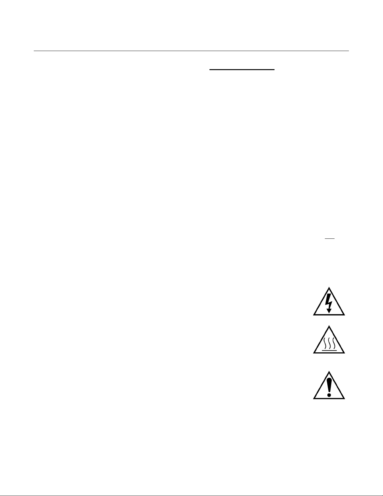
Instruction Manual
IM-106-5500, Original Issue
August 2005
CCO 5500
BELANGRIJK
Veiligheidsvoorschriften voor de aansluiting en installatie van dit
toestel.
De hierna volgende veiligheidsvoorschriften zijn vooral bedoeld voor de
EU lidstaten. Hier moet aan gehouden worden om de onderworpenheid
aan de Laag Spannings Richtlijn (Low Voltage Directive) te verzekeren.
Niet EU staten zouden deze richtlijnen moeten volgen tenzij zij reeds
achterhaald zouden zijn door plaatselijke of nationale voorschriften.
1. Degelijke aardingsaansluitingen moeten gemaakt worden naar alle voorziene aardpunten, intern en extern.
2. Na installatie of controle moeten alle veiligheidsdeksels en -aardingen terug geplaatst worden. Ten alle tijde moet de betrouwbaarheid van de aarding behouden blijven.
3. Voedingskabels moeten onderworpen zijn aan de IEC227 of de IEC245 voorschriften.
4. Alle bekabeling moet geschikt zijn voor het gebruik in
omgevingstemperaturen, hoger dan 75°C.
5. Alle wartels moeten zo gedimensioneerd zijn dat een degelijke kabel bevestiging verzekerd is.
6. Om de veilige werking van dit toestel te verzekeren, moet de voeding
door een stroomonderbreker gevoerd worden (min 10A) welke alle
draden van de voeding moet onderbreken. De stroomonderbreker mag
een mechanische schakelaar bevatten. Zoniet moet een andere
mogelijkheid bestaan om de voedingsspanning van het toestel te halen
en ook duidelijk zo zijn aangegeven. Stroomonderbrekers of
schakelaars moeten onderworpen zijn aan een erkende standaard
zoals IEC947.
7. Waar toestellen of deksels aangegeven staan met het symbool is er meestal hoogspanning aanwezig. Deze deksels mogen enkel verwijderd worden nadat de voedingsspanning werd afgelegd en enkel door getraind onderhoudspersoneel.
8. Waar toestellen of deksels aangegeven staan met het
symbool is er gevaar voor hete oppervlakken. Deze
deksels mogen enkel verwijderd worden door getraind
onderhoudspersoneel nadat de voedingsspanning
verwijderd werd. Sommige oppper-vlakken kunnen 45
minuten later nog steeds heet aanvoelen.
9. Waar toestellen of deksels aangegeven staan met het symbool gelieve het handboek te raadplegen.
10. Alle grafische symbolen gebruikt in dit produkt, zijn afkomstig uit een of meer van devolgende standaards: EN61010-1, IEC417 en ISO3864.
A-3
Page 96

CCO 5500
Instruction Manual
IM-106-5500, Original Issue
August 2005
VIGTIGT
Sikkerhedsinstruktion for tilslutning og installering af dette udstyr.
Følgende sikkerhedsinstruktioner gælder specifikt i alle
EU-medlemslande. Instruktionerne skal nøje følges for overholdelse af
Lavsspændingsdirektivet og bør også følges i ikke EU-lande medmindre
andet er specificeret af lokale eller nationale standarder.
1. Passende jordforbindelser skal tilsluttes alle jordklemmer, interne og eksterne, hvor disse forefindes.
2. Efter installation eller fejlfinding skal alle sikkerhedsdæksler og jordforbindelser reetableres.
3. Forsyningskabler skal opfylde krav specificeret i IEC227 eller IEC245.
4. Alle ledningstilslutninger skal være konstrueret til omgivelsestemperatur
højere end 75°C.
5. Alle benyttede kabelforskruninger skal have en intern dimension, så passende kabelaflastning kan etableres.
6. For opnåelse af sikker drift og betjening skal der skabes beskyttelse
mod indirekte berøring gennem afbryder (min. 10A), som vil afbryde alle
kredsløb med elektriske ledere i fejlsitua-tion. Afbryderen skal indholde
en mekanisk betjent kontakt. Hvis ikke skal anden form for afbryder
mellem forsyning og udstyr benyttes og mærkes som sådan. Afbrydere
eller kontakter skal overholde en kendt standard som IEC947.
7. Hvor udstyr eller dæksler er mærket med dette symbol, er farlige spændinger normalt forekom-mende bagved. Disse dæksler bør kun afmonteres, når forsyningsspændingen er frakoblet - og da kun af instrueret servicepersonale.
8. Hvor udstyr eller dæksler er mærket med dette symbol,
forefindes meget varme overflader bagved. Disse
dæksler bør kun afmonteres af instrueret
servicepersonale, når forsyningsspænding er frakoblet.
Visse overflader vil stadig være for varme at berøre i op
til 45 minutter efter frakobling.
9. Hvor udstyr eller dæksler er mærket med dette symbol, se da i betjeningsmanual for instruktion.
10. Alle benyttede grafiske symboler i dette udstyr findes i én eller flere af følgende standarder:- EN61010-1, IEC417 & ISO3864.
A-4
Page 97

Instruction Manual
IM-106-5500, Original Issue
August 2005
CCO 5500
BELANGRIJK
Veiligheidsinstructies voor de bedrading en installatie van dit apparaat.
Voor alle EU lidstaten zijn de volgende veiligheidsinstructies van
toepassing. Om aan de geldende richtlijnen voor laagspanning te
voldoen dient men zich hieraan strikt te houden. Ook niet EU lidstaten
dienen zich aan het volgende te houden, tenzij de lokale wetgeving
anders voorschrijft.
1. Alle voorziene interne- en externe aardaansluitingen dienen op adequate wijze aangesloten te worden.
2. Na installatie, onderhouds- of reparatie werkzaamheden dienen alle beschermdeksels /kappen en aardingen om reden van veiligheid weer aangebracht te worden.
3. Voedingskabels dienen te voldoen aan de vereisten van de normen IEC 227 of IEC 245.
4. Alle bedrading dient geschikt te zijn voor gebruik bij een omgevings
temperatuur boven 75°C.
5. Alle gebruikte kabelwartels dienen dusdanige inwendige afmetingen te hebben dat een adequate verankering van de kabel wordt verkregen.
6. Om een veilige werking van de apparatuur te waarborgen dient de
voeding uitsluitend plaats te vinden via een meerpolige automatische
zekering (min.10A) die alle
indien een foutconditie optreedt. Deze automatische zekering mag ook
voorzien zijn van een mechanisch bediende schakelaar. Bij het
ontbreken van deze voorziening dient een andere als zodanig duidelijk
aangegeven mogelijkheid aanwezig te zijn om de spanning van de
apparatuur af te schakelen. Zekeringen en schakelaars dienen te
voldoen aan een erkende standaard zoals IEC 947.
7. Waar de apparatuur of de beschermdeksels/kappen
gemarkeerd zijn met het volgende symbool, kunnen
zich hieronder spanning voerende delen bevinden die
gevaar op kunnen leveren. Deze beschermdeksels/
kappen mogen uitsluitend verwijderd worden door
getraind personeel als de spanning is afgeschakeld.
8. Waar de apparatuur of de beschermdeksels/kappen gemarkeerd zijn met het volgende symbool, kunnen zich hieronder hete oppervlakken of onderdelen bevinden. Bepaalde delen kunnen mogelijk na 45 min. nog te heet zijn om aan te raken.
9. Waar de apparatuur of de beschermdeksels/kappen gemarkeerd zijn met het volgende symbool, dient men de bedieningshandleiding te raadplegen.
10. Alle grafische symbolen gebruikt bij dit produkt zijn volgens een of meer van de volgende standaarden: EN 61010-1, IEC 417 & ISO 3864.
spanningvoerende geleiders verbreekt
A-5
Page 98

CCO 5500
Instruction Manual
IM-106-5500, Original Issue
August 2005
TÄRKEÄÄ
Turvallisuusohje, jota on noudatettava tämän laitteen asentamisessa ja
kaapeloinnissa.
Seuraavat ohjeet pätevät erityisesti EU:n jäsenvaltioissa. Niitä täytyy
ehdottomasti noudattaa jotta täytettäisiin EU:n matalajännitedirektiivin
(Low Voltage Directive) yhteensopivuus. Myös EU:hun kuulumattomien
valtioiden tulee nou-dattaa tätä ohjetta, elleivät kansalliset standardit
estä sitä.
1. Riittävät maadoituskytkennät on tehtävä kaikkiin maadoituspisteisiin, sisäisiin ja ulkoisiin.
2. Asennuksen ja vianetsinnän jälkeen on kaikki suojat ja suojamaat asennettava takaisin pai-koilleen. Maadoitusliittimen kunnollinen toiminta täytyy aina ylläpitää.
3. Jännitesyöttöjohtimien täytyy täyttää IEC227 ja IEC245 vaatimukset.
4. Kaikkien johdotuksien tulee toimia >75°C lämpötiloissa.
5. Kaikkien läpivientiholkkien sisähalkaisijan täytyy olla sellainen että kaapeli lukkiutuu kun-nolla kiinni.
6. Turvallisen toiminnan varmistamiseksi täytyy jännitesyöttö varustaa
turvakytkimellä (min 10A), joka kytkee irti kaikki jännitesyöttöjohtimet
vikatilanteessa. Suojaan täytyy myös sisältyä mekaaninen erotuskytkin.
Jos ei, niin jännitesyöttö on pystyttävä katkaisemaan muilla keinoilla ja
merkittävä siten että se tunnistetaan sellaiseksi. Turvakytkimien tai
kat-kaisimien täytyy täyttää IEC947 standardin vaatimukset
näkyvyydestä.
7. Mikäli laite tai kosketussuoja on merkitty tällä merkillä on merkinnän takana tai alla hengenvaarallisen suuruinen jännite. Suojaa ei saa poistaa jänniteen ollessa kytkettynä laitteeseen ja poistamisen saa suorittaa vain alan asian-tuntija.
8. Mikäli laite tai kosketussuoja on merkitty tällä merkillä on merkinnän takana tai alla kuuma pinta. Suojan saa poistaa vain alan asiantuntija kun jännite-syöttö on katkaistu. Tällainen pinta voi säilyä kosketuskuumana jopa 45 mi-nuuttia.
9. Mikäli laite tai kosketussuoja on merkitty tällä merkillä katso lisäohjeita käyt-töohjekirjasta.
10. Kaikki tässä tuotteessa käytetyt graafiset symbolit ovat yhdestä tai useammasta seuraavis-ta standardeista: EN61010-1, IEC417 & ISO3864.
A-6
Page 99

Instruction Manual
IM-106-5500, Original Issue
August 2005
CCO 5500
IMPORTANT
Consignes de sécurité concernant le raccordement et l'installation de
cet appareil.
Les consignes de sécurité ci-dessous s'adressent particulièrement à
tous les états membres de la communauté européenne. Elles doivent
être strictement appliquées afin de satisfaire aux directives concernant
la basse tension. Les états non membres de la communauté
européenne doivent également appliquer ces consignes sauf si elles
sont en contradiction avec les standards locaux ou nationaux.
1. Un raccordement adéquat à la terre doit être effectuée à chaque borne de mise à la terre, interne et externe.
2. Après installation ou dépannage, tous les capots de protection et toutes les prises de terre doivent être remis en place, toutes les prises de terre doivent être respectées en permanence.
3. Les câbles d'alimentation électrique doivent être conformes aux normes IEC227 ou IEC245.
4. Tous les raccordements doivent pouvoir supporter une température
ambiante supérieure à 75°C.
5. Tous les presse-étoupes utilisés doivent avoir un diamètre interne en rapport avec les câbles afin d'assurer un serrage correct sur ces derniers.
6. Afin de garantir la sécurité du fonctionnement de cet appareil, le
raccordement à l'alimentation électrique doit être réalisé exclusivement
au travers d'un disjoncteur (minimum 10A.) isolant tous
en cas d'anomalie. Ce disjoncteur doit également pouvoir être actionné
manuellement, de façon mécanique. Dans le cas contraire, un autre
système doit être mis en place afin de pouvoir isoler l'appareil et doit
être signalisé comme tel. Disjoncteurs et interrupteurs doivent être
conformes à une norme reconnue telle IEC947.
7. Lorsque les équipements ou les capots affichent le symbole suivant, cela signifie que des tensions dangereuses sont présentes. Ces capots ne doivent être démontés que lorsque l'alimentation est coupée, et uniquement par un personnel compétent.
8. Lorsque les équipements ou les capots affichent le
symbole suivant, cela signifie que des surfaces
dangereusement chaudes sont présentes. Ces capots
ne doivent être démontés que lorsque l'alimentation est
coupée, et uniquement par un personnel compétent.
Certaines surfaces peuvent rester chaudes jusqu'à 45
mn.
9. Lorsque les équipements ou les capots affichent le symbole suivant, se reporter au manuel d'instructions.
10. Tous les symboles graphiques utilisés dans ce produit sont conformes à un ou plusieurs des standards suivants: EN61010-1, IEC417 & ISO3864.
les conducteurs
A-7
Page 100
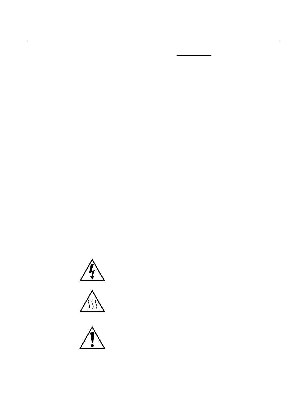
CCO 5500
Instruction Manual
IM-106-5500, Original Issue
August 2005
WICHTIG
Sicherheitshinweise für den Anschluß und die Installation dieser
Geräte.
Die folgenden Sicherheitshinweise sind in allen Mitgliederstaaten der
europäischen Gemeinschaft gültig. Sie müssen strickt eingehalten
werden, um der Niederspannungsrichtlinie zu genügen.
Nichtmitgliedsstaaten der europäischen Gemeinschaft sollten die
national gültigen Normen und Richtlinien einhalten.
1. Alle intern und extern vorgesehenen Erdungen der Geräte müssen ausgeführt werden.
2. Nach Installation, Reparatur oder sonstigen Eingriffen in das Gerät müssen alle Sicherheitsabdeckungen und Erdungen wieder installiert werden. Die Funktion aller Erdverbindungen darf zu keinem Zeitpunkt gestört sein.
3. Die Netzspannungsversorgung muß den Anforderungen der IEC227 oder IEC245 genügen.
4. Alle Verdrahtungen sollten mindestens bis 75°C ihre Funktion dauerhaft
erfüllen.
5. Alle Kabeldurchführungen und Kabelverschraubungen sollten in Ihrer Dimensionierung so gewählt werden, daß diese eine sichere Verkabelung des Gerätes ermöglichen.
6. Um eine sichere Funktion des Gerätes zu gewährleisten, muß die
Spannungsversorgung über mindestens 10 A abgesichert sein. Im
Fehlerfall muß dadurch gewährleistet sein, daß die
Spannungsversorgung zum Gerät bzw. zu den Geräten unterbrochen
wird. Ein mechanischer Schutzschalter kann in dieses System integriert
werden. Falls eine derartige Vorrichtung nicht vorhanden ist, muß eine
andere Möglichkeit zur Unterbrechung der Spannungszufuhr
gewährleistet werden mit Hinweisen deutlich gekennzeichnet werden.
Ein solcher Mechanismus zur Spannungsunterbrechung muß mit den
Normen und Richtlinien für die allgemeine Installation von
Elektrogeräten, wie zum Beispiel der IEC947, übereinstimmen.
7. Mit dem Symbol sind Geräte oder Abdeckungen gekennzeichnet, die
eine gefährliche (Netzspannung) Spannung führen. Die Abdeckungen
dürfen nur entfernt werden, wenn die Versorgungsspannung
unterbrochen wurde. Nur geschultes Personal darf an diesen Geräten
Arbeiten ausführen.
8. Mit dem Symbol sind Geräte oder Abdeckungen gekennzeichnet, in
bzw. unter denen heiße Teile vorhanden sind. Die Abdeckungen dürfen
nur entfernt werden, wenn die Versorgungsspannung unterbrochen
wurde. Nur geschultes Personal darf an diesen Geräten Arbeiten
ausführen. Bis 45 Minuten nach dem Unterbrechen der Netzzufuhr
können derartig Teile noch über eine erhöhte Temperatur verfügen.
9. Mit dem Symbol sind Geräte oder Abdeckungen gekennzeichnet, bei denen vor dem Eingriff die entsprechenden Kapitel im Handbuch sorgfältig durchgelesen werden müssen.
10. Alle in diesem Gerät verwendeten graphischen Symbole entspringen einem oder mehreren der nachfolgend aufgeführten Standards: EN61010-1, IEC417 & ISO3864.
A-8
 Loading...