

Page 1
Rosemount Analytical
NGA 2000
Software Manual
MLT Analyzer
ML T Analyzer Module
(combined with NGA 2000 platform /
MLT analyzer / TFID analyzer
or customer-developed control unit)
Software V ersion 3.2.X
2nd Edition 07/98
90003482(2) [NGA-e (MLT-Software 3.2.X)] 07/98
Catalog No.: 90 003 482
Managing The Process Better
Page 2
Rosemount Analytical
This Operation Manual includes information about the operation of the instrument.
Information about the additional indications and notes regarding maintenance, troubleshooting and repair
are found in the accompanying Maintenance & Operation Manual.
T roubleshooting, component replacement and internal adjustments must be made by qualified
service personnel only.
Fisher-Rosemount GmbH & Co does not take responsibility for an y omissions or errors in this manual.
Any liability for direct or indirect damages, which might occur in connection with the deliv ery or the use of
this manual, is expressly e xcluded to the extend permitted by applicable law.
This instrument has left the works in good order according to safety regulations.
T o maintain this operating condition, the user must strictly follow the instructions and consider the warnings
in this manual or provided on the instrument.
Misprints and alterations reserved
©
1998 by FISHER-ROSEMOUNT GmbH & Co. (ETC/PAD)
st
1
Edition: 04/98
2nd Edition: 07/98
Read this operation manual carefully before attempting to operate the analyzer !
For expedient handling of reports of defects , please include the model and serial number which
can be read on the instrument identity plate.
Fisher - Rosemount GmbH & Co.
European T echnology Center
Industriestrasse 1
D - 63594 Hasselroth • Germany
Phone + 49 (6055) 884-0
T elefax + 49 (6055) 884-209
Internet: http://www.processanalytic.com
90003482(2) [NGA-e (MLT-Software 3.2.X)] 07/98
Page 3

Contents
1 Introduction 1 - 1
2 Structure of Menus 2 - 1
3 Startup and Operation, General Notes and Main Menu 3 - 1
3.1 Starting and Initializing...................................................................................3 - 1
3.2 Display and Function...................................................................................... 3 - 2
3.3 "TAG" and Operating Keys ............................................................................3 - 2
3.4 Lines and Softkey Functionality .....................................................................3 - 3
3.5 Important Functions of the Softkeys...............................................................3 - 4
3.6 Entering/Changing of Variables......................................................................3 - 5
3.7 Starting a Function.........................................................................................3 - 6
3.8 Main Menu .....................................................................................................3 - 7
4 Basic Controls and Analyzer Module Calibration 4 - 1
4.1 Analyzer Channel Status................................................................................ 4 - 3
4.1.1 Status Details – Failures...............................................................................4 - 5
– Maintenance requests ........................................................4 - 7
– Function controls ................................................................4 -11
– Measurements/Alarms........................................................4 -13
– Events.................................................................................4 -15
– Acknowledge and clear failures..........................................4 -19
– Acknowledge and clear maintenance requests ..................4 -23
– Acknowledge and clear function controls............................4 -27
4.1.2 Operational Settings.......................................................................................4 -31
4.2 Single Component Display - Change of Channel...........................................4 -33
4.3 Multi Component Display - Change of Channel.............................................4 -35
4.4 Calibration Procedure Status......................................................................... 4 -37
4.5 Zero Calibration..............................................................................................4 -39
4.6 Span Calibration.............................................................................................4 -43
4.7 Flow Zero Gas................................................................................................ 4 -47
4.8 Flow Span Gas...............................................................................................4 -51
4.9 Flow Sample Gas...........................................................................................4 -55
4.10 Flow Test Gas................................................................................................4 -59
4.11 Close all Valves.............................................................................................. 4 -63
90003482(2) [NGA-e (MLT-Software 3.2.X)] 07/98
NGA 2000
I
Page 4

5 Analyzer and I/O-Module Expert Configuration 5 - 1
5.1 Analyzer Module Setup 5 - 3
5.1.1 Calibration Parameters...................................................................................5 - 5
– Span gases.........................................................................................5 - 6
– Tolerances ..........................................................................................5 - 7
– Calibration procedure setup................................................................5 - 9
– Time controlled calibration..................................................................5 -12
– Calibration...........................................................................................5 -15
– Advanced calibration methods............................................................5 -18
– Zero gases..........................................................................................5 -20
5.1.2 Alarm Parameters...........................................................................................5 -21
5.1.3 Range Parameters .........................................................................................5 -25
– Begin and end of ranges.....................................................................5 -27
– Response times (t90) ...........................................................................5 -28
– Autoranging control.............................................................................5 -29
5.1.4 Cross Interference Compensation..................................................................5 -31
5.1.5 Linearization...................................................................................................5 -33
5.1.6 Programmable Logic Control (PLC)................................................................5 -37
5.1.7 Programmable Calculator...............................................................................5 -45
5.1.8 Measurement Display Configuration...............................................................5 -49
5.1.9 Acknowledgement of Status Reports..............................................................5 -52
5.1.10 Concentration Measurement Parameters.......................................................5 -54
5.1.11 Peak Measurement ........................................................................................5 -55
5.1.12 Differential Measurement ...............................................................................5 -57
5.1.13 Gasflow Setup................................................................................................5 -59
5.1.14 Pressure Compensation.................................................................................5 -60
5.1.15 Flow Measurement.........................................................................................5 -62
5.1.16 Temperature Measurement............................................................................5 -63
5.1.17 Loading/Saving Configuration Parameters.....................................................5 -64
5.1.18 Inputs and Outputs.........................................................................................5 -67
– Local SIO ............................................................................................5 -68
– Local DIO............................................................................................5 -74
– Signal codes........................................................................................5 -75
5.1.19 Delay and Average.........................................................................................5 -79
5.1.20 Special Functions...........................................................................................5 -81
5.1.21 AK-Protocol Communication ..........................................................................5 -82
II
NGA 2000
90003482(2) [NGA-e (MLT-Software 3.2.X)] 07/98
Page 5

5.2 I/O Module Controls 5 -83
5.2.1 SIO Module 5 -84
5.2.2 DIO Module(s) 5 -93
5.3 I/O Module Setup 5 -99
6 System Configuration 6 - 1
6.1 Diagnostic Menus........................................................................................... 6 - 3
6.1.1 Control Module Diagnostics................................................................. 6 - 4
6.1.2 Analyzer Module Diagnostics .............................................................. 6 - 5
6.2 Date and Time................................................................................................6 - 6
6.3 Security Codes...............................................................................................6 - 7
6.4 Network Module Binding ................................................................................6 - 9
6.5 System Reset.................................................................................................6 -11
6.6 System Modules.............................................................................................6 -12
7 Display Controls 7 - 1
Index
Supplement: System Calibration
90003482(2) [NGA-e (MLT-Software 3.2.X)] 07/98
NGA 2000
III
Page 6

IV
NGA 2000
90003482(2) [NGA-e (MLT-Software 3.2.X)] 07/98
Page 7
1 Introduction
This software manual describes step by step how to operate successfully with the ½ 19"
and 19" MLT analyzer module and analyzer of the NGA 2000 Series.
Chapter two shows the structure of the MLT software menus. Chapter three describes the
display and the keyboard of the analyzer. Chapter four describes the basic controls with
detailed illustrations. So you can easily compare the actual display of the analyzer module
with the illustrations of the manual.
Chapter five describes the expert configurations of the analyzer module and of the Input/
Output Modules (I/O modules). Chapter six describes the system configuration. The layout
of both chapters is not as detailed as in chapter four. Normally, the way to a certain menu
of the MLT software is described with the software catchwords you have to press to reach
this menu. You will find the illustration of the corresponding LCD screen at the end of the
catchword listing. After that you can read the meaning of the functions and variables of
each expert or system configuration menu.
Some contents of the expert configurations are not important for each customer. It depends
on the configuration of your NGA 2000 system, relative to the following components:
♦ Control Module CM
♦ Analyzer Module AM
♦ Input/Output Modules I/O's (SIO = Standard I/O, DIO = Digital I/O,
System Auto Calibration I/O, Analog Output with 3 Alarms I/O,
Auto Calibration I/O)
You can distinguish the following system units and SIO/DIO configurations:
System Unit SIO/DIO-Configuration
MLT analyzer module (AM):
• without front panel,
i.e. without control unit
• can be combined with a platform,
an MLT analyzer, a TFID analyzer
or a customer developed control
⇒ 1 local SIO and 1 local DIO can be
installed in the MLT analyzer
module
⇒ SIO and DIO can be configured
for the channels of the analyzer
module only
unit
Platform (CM Software):
• Control unit with front panel
• Without measurement channels
⇒ 1 SIO and up to 4 DIO's can be
installed in the platform (CM I/O)
⇒ SIO and DIO can be configured
for all channels combined with the
platform
Section
Page
∗ 5.1.18
p. 5-67
∗ 5.2
p. 5-83
MLT analyzer (CM and MLT AM
software):
• Analyzer with front panel
• CM and AM software in the same
analyzer,
i.e. all functions of the control unit
and of the AM are combined in one
controller board
90003482(2) [NGA-e (MLT-Software 3.2.X)] 07/98
⇒ 1 SIO and 1 DIO can be installed
in the MLT analyzer (CM I/O)
⇒ SIO and DIO can be configured
for all channels combined with the
MLT analyzer
NGA 2000
∗ 5.2
p. 5-83
1 - 1
Page 8
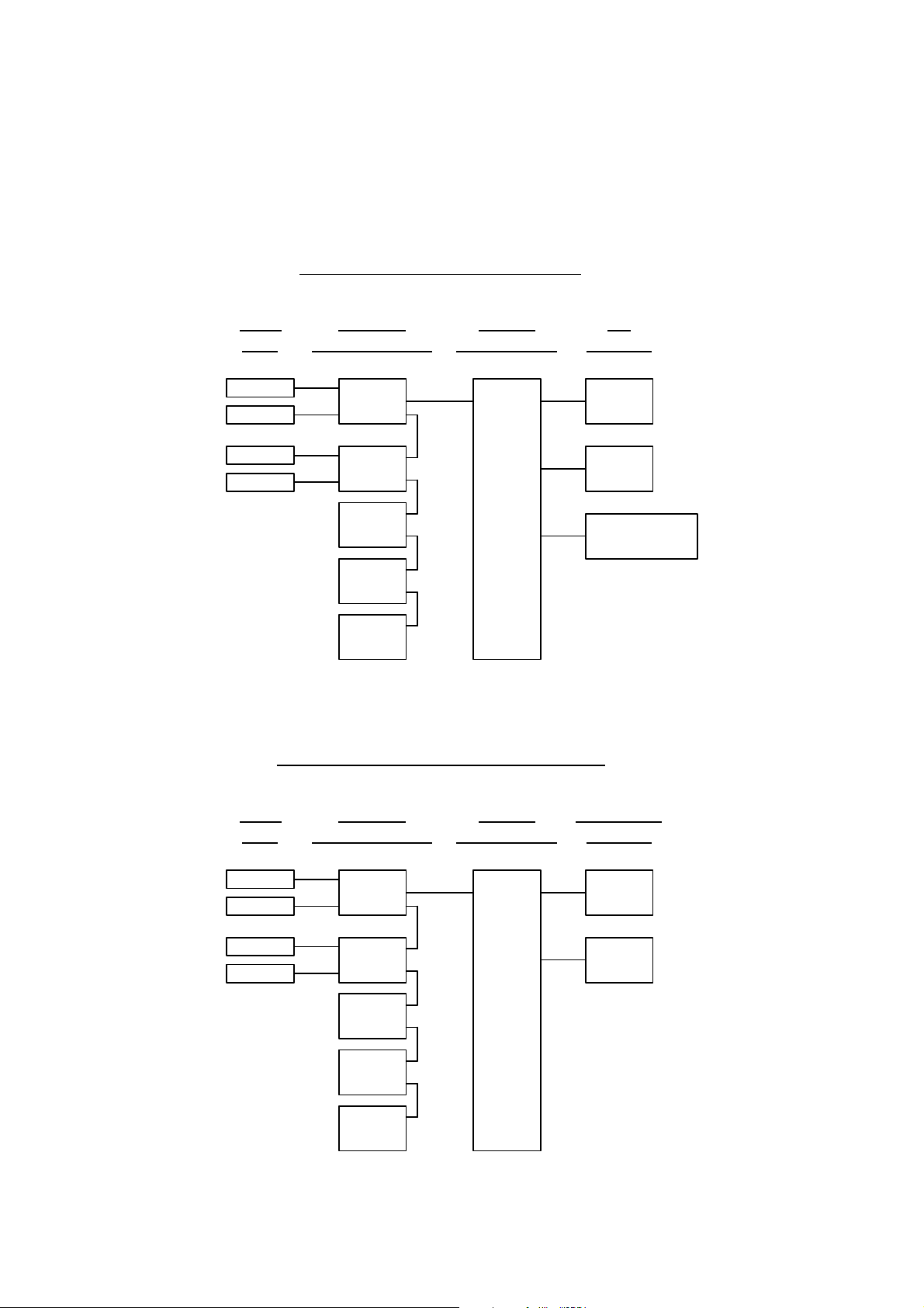
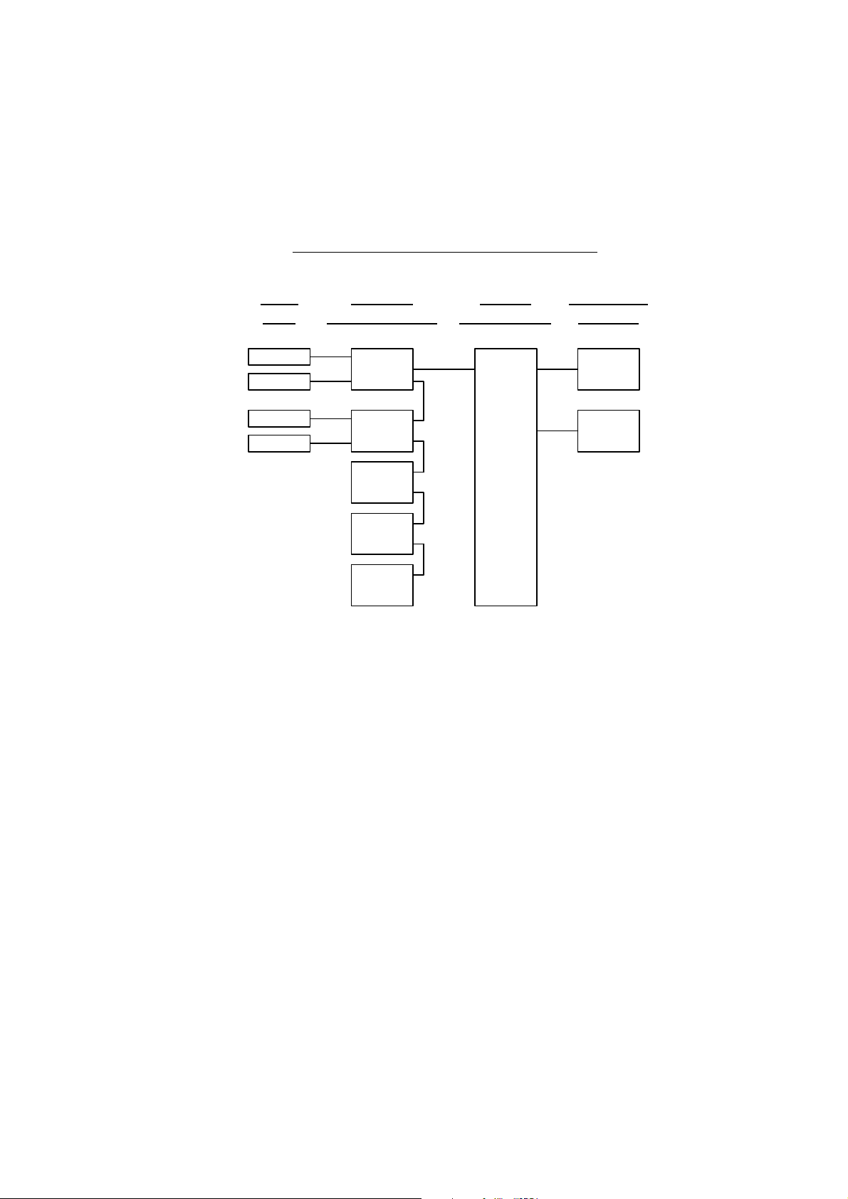
The following illustrations shall make plain the connection between the hardware configuration and the software setup of the modules:
NGA 2000 System via Platform
(see 5.1.18)
(see 5.1.18)
Local
I/O's
SIO
DIO
SIO
DIO
(additional
manuals)
(additional
manuals)
(additional
manuals)
NGA 2000 System via MLT Analyzer
Analyzer
Modules (AM's)
TFID
MLT
CLD
PMD
FID
Control
Module (CM)
Platform
I/O
Modules
1 SIO
4 DIO's
max.
Other I/O's
(see 5.2.1)
(see 5.2.2)
(see 5.1.18)
(see 5.1.18)
1 - 2
Local
I/O's
SIO
DIO
SIO
DIO
(additional
manuals)
(additional
manuals)
(additional
manuals)
Analyzer
Modules (AM's)
MLT
TFID
CLD
PMD
FID
NGA 2000
Control
Module (CM)
MLT Analyzer
System I/O
Modules
1 SIO
1 DIO
90003482(2) [NGA-e (MLT-Software 3.2.X)] 07/98
(see 5.2.1)
(see 5.2.2)
Page 9
NGA 2000 System via TFID Analyzer
1 Introduction
(see 5.1.18)
(see 5.1.18)
Local
I/O's
SIO
DIO
SIO
DIO
(additional
manuals)
(additional
manuals)
(additional
manuals)
Analyzer
Modules (AM's)
TFID
MLT
CLD
PMD
FID
Control
Module (CM)
TFID Analyzer
System I/O
Modules
1 SIO
1 DIO
(see 5.2.1)
(see 5.2.2)
90003482(2) [NGA-e (MLT-Software 3.2.X)] 07/98
NGA 2000
1 - 3
Page 10

1 - 4
NGA 2000
90003482(2) [NGA-e (MLT-Software 3.2.X)] 07/98
Page 11
90003482(2) [NGA-e (MLT-Software 3.2.X)] 07/98
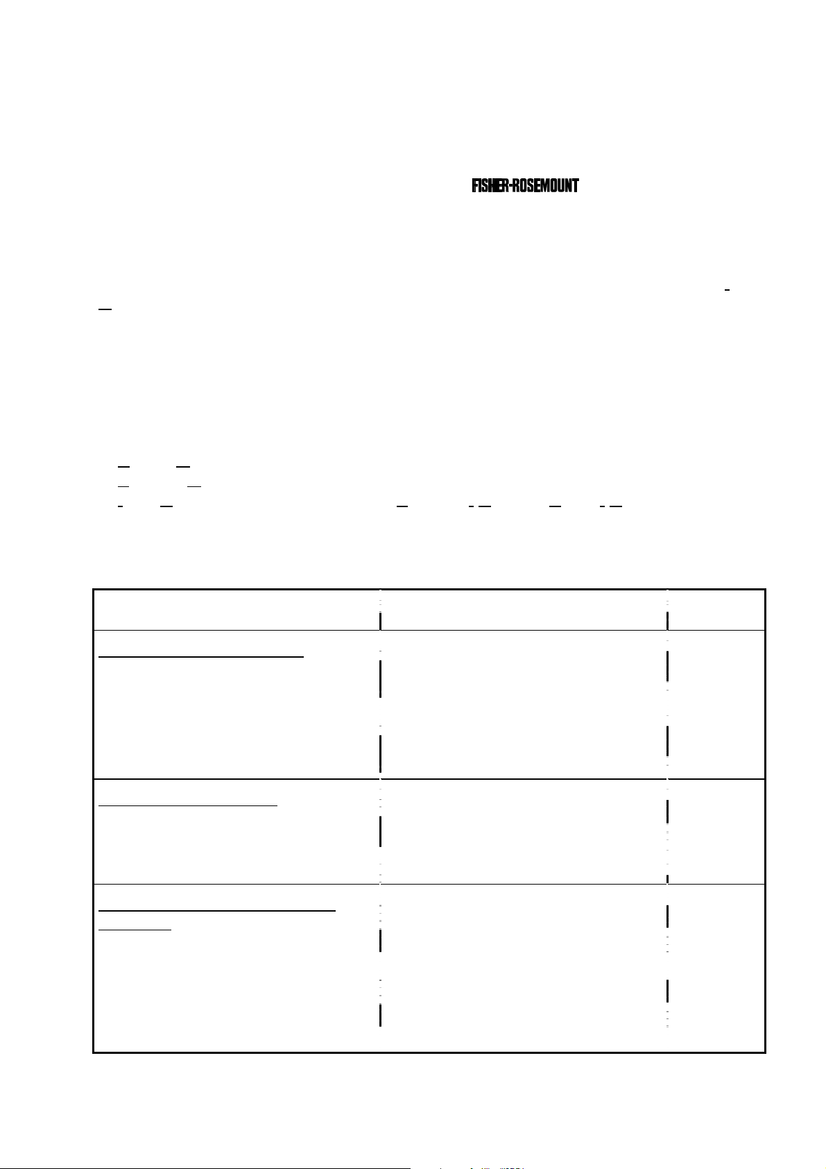
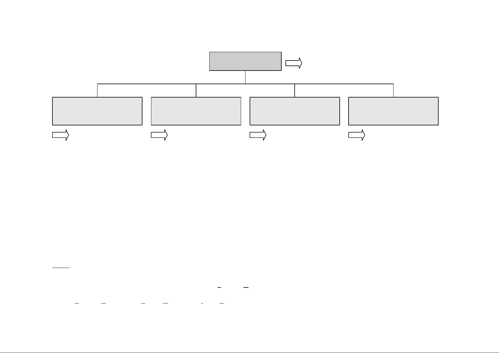
enu lines ending with three points (...) are followed by submenus with further functions and set-ups.
All set-ups in the menu "Basic controls" are valid for the
At each menu point of the "Expert configuration" and "System configuration" you can find which functionality will be set up:
nalyzer Module), CM (
odule), I/O (
utput Module).
-
-
-
-
NGA 2000
Analyzer module
calibration & basic
controls... (AM)
Section 4 Section 5 Section 6 Section 7
Calibration procedure
status...
Zero calibration of all
ranges
Span calibration of the
current range
Current gas valve setting:
- Zero gas flow
- Span gas flow
- Sample gas flow
- Test gas flow
- Closing all valves
Main Menu
Analyzer and I/O-
module expert
configuration...
- Analyzer module
controls... (AM)
- I/O module controls...
(I/O's: SIO, DIO)
- Analyzer module setup...
(AM)
- I/O module setup...
(Other micro processor
controlled I/O's)
Section 3.8
System configuration
and diagnostics...
- System calibration... (CM)
- Diagnostic menus...
(AM, CM, I/O's: SIO, DIO
and other I/O's)
- Date and time... (CM)
- Security codes...
(Lock of each level)
- Network module binding...
(AM, CM, I/O's: SIO, DIO
and other I/O's)
- System reset... (CM)
- System modules... (CM)
- System tag (CM)
Display controls...
- Display controls of the
front panel LCD
- Front panel control
(number of digits)
- Auxiliary lines
(for the
single component display)
2 Structure of Menus
Notes:
* M
*
*
AM (A
2 - 1
Control M
analyzer module (AM).
Input-/O
Page 12

2 - 2
NGA 2000
90003482(2) [NGA-e (MLT-Software 3.2.X)] 07/98
Page 13
3 Startup and Operation, General Notes and Main Menu
3.1 Starting and Initializing
After switching on the MLT analyzer or analyzer module (in a platform or part of a NGA
network), the initialization procedure will be performed. A self control of the analyzer
modules or the analyzer is running. You can see a sequence of several displays. They
show the status of initialization, revision notes of the MLT software and the
tag:
(C) 1998 FISHER-ROSEMOUNT Analytical
NGA-2000 Control Module/Version 3.2.1
Initializing Network
Initializing network interface
LCDReset Abort
F1 F2 F3 F4 F5
If you press the F1 key during the initializing, you will reset the LCD brightness and
contrast to factory settings (see also section 7). Pressing the F3 key will abort the network
initializing. Then you will have no connection to any analyzer module. Only the menus of
the platform will be available.
At the end of the initializing procedure you can see the single component display of
channel one (see illustration on next page). It is the origin to all the other channels, menus
and submenus.
The instructions of the basic controls (chapter four) are all beginning with the single component display. The actual display might differ from the shown one because the customer
can configure it according to his requirements (see section 5.1.8 p. 5-49 and section 7).
90003482(2) [NGA-e (MLT-Software 3.2.X)] 07/98
NGA 2000
3 - 1
Page 14
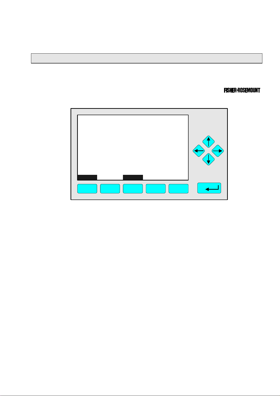
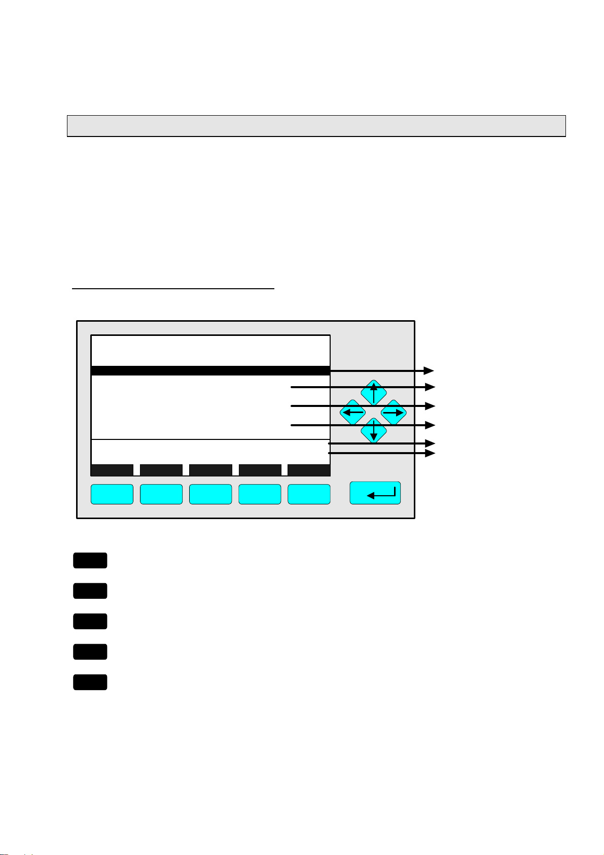
3.2 Display and Function
The LCD screen shows all measurement values of the analyzer and all customer
instructions. You can operate with five function keys, four arrow keys (cursors) and the
enter key. The function of each key depends on:
♦ the type of analyzer/analyzer module used
♦ the optional auxiliary modules (e.g. I/O boards) used
♦ the individual menu displayed
In case of power failure all customer specific module parameters are saved by a batterypowered buffer.
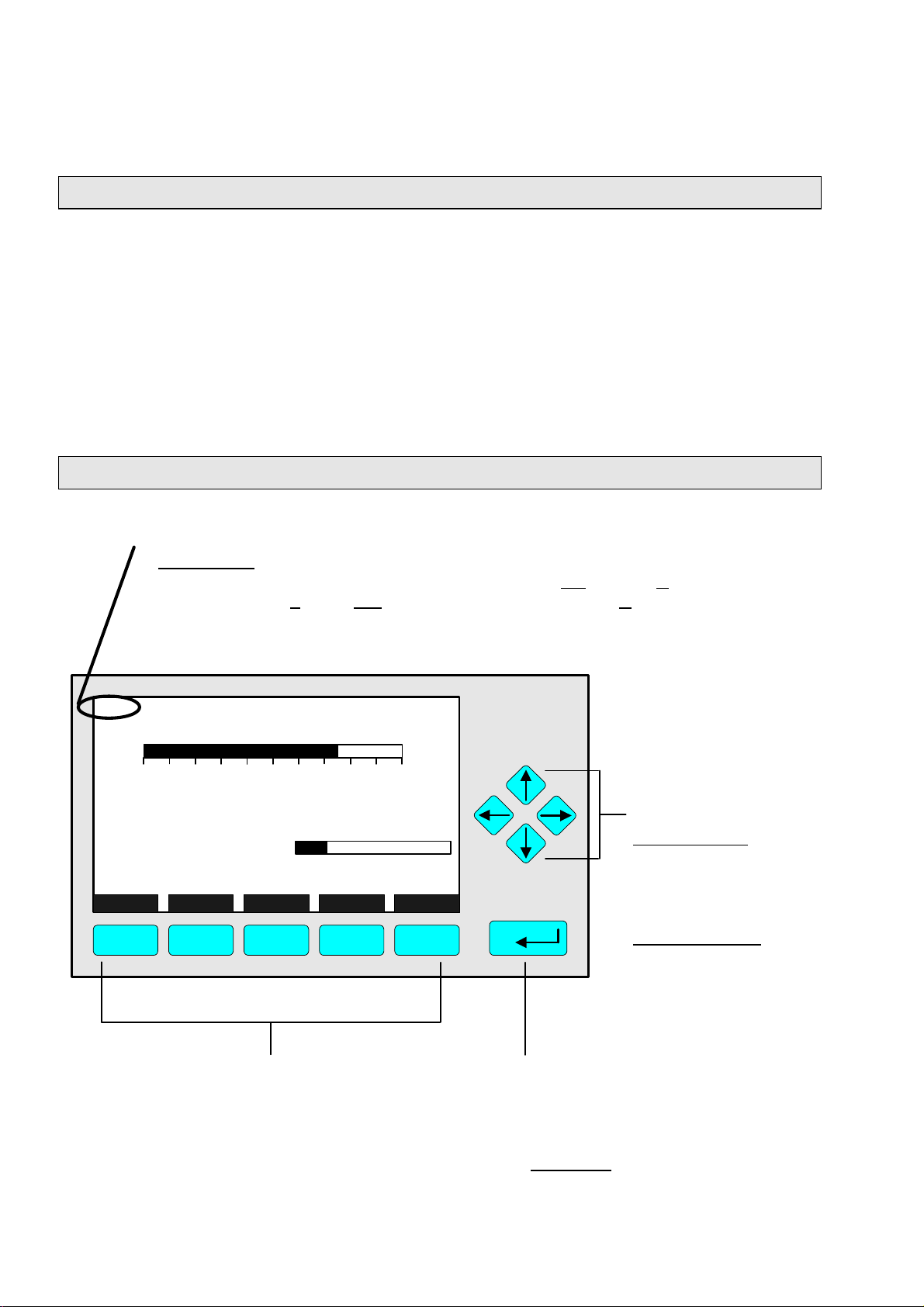
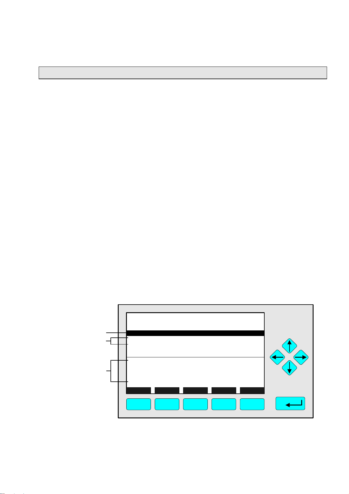
3.3 "TAG" and Operating Keys
At the top left of each menu page you will find the tag of the current channel.
Typical tags:
♦ MLT/CH1/R1: MLT Analyzer or Analyzer Module / CHannel 1 / Range 1
♦ TFID-R1: Thermo FID Analyzer or Analyzer Module - Range 1
In this manual you will find normally "TAG" as general name. But in the specific MLT
menu pages you will find "MLT".
TAG
37.50 ppm CH4
0.00 50.00
Failures: No
Maintenance-Requests: No
Temperature: 20.0 C
Operation: Ready
Display Status... Main... Channel Calib...
F1 F2 F3 F4 F5
Function Keys:
♦ keys without defined functions
♦ The current function depends on
the menu selected
♦ The softkey legend is shown on
the display above the key
Range: 1
0.0 100.0
Cursor keys:
↑↑ -key / ↓↓ -key:
♦ Line up / line down
within the same menu
♦ Alteration of numbers,
variables or digits
←← -key / →→ -key:
♦ Moving back/forwards
between the pages of
a menu
♦ Selection of digits
Enter Key:
♦ To confirm a previously entered value
(variable)
♦ To start a selected function
(Alternative: →→ -key)
♦ To go into a menu (via menu line)
3 - 2
NGA 2000
90003482(2) [NGA-e (MLT-Software 3.2.X)] 07/98
Page 15
3 Startup and Operation, General Notes and Main Menu
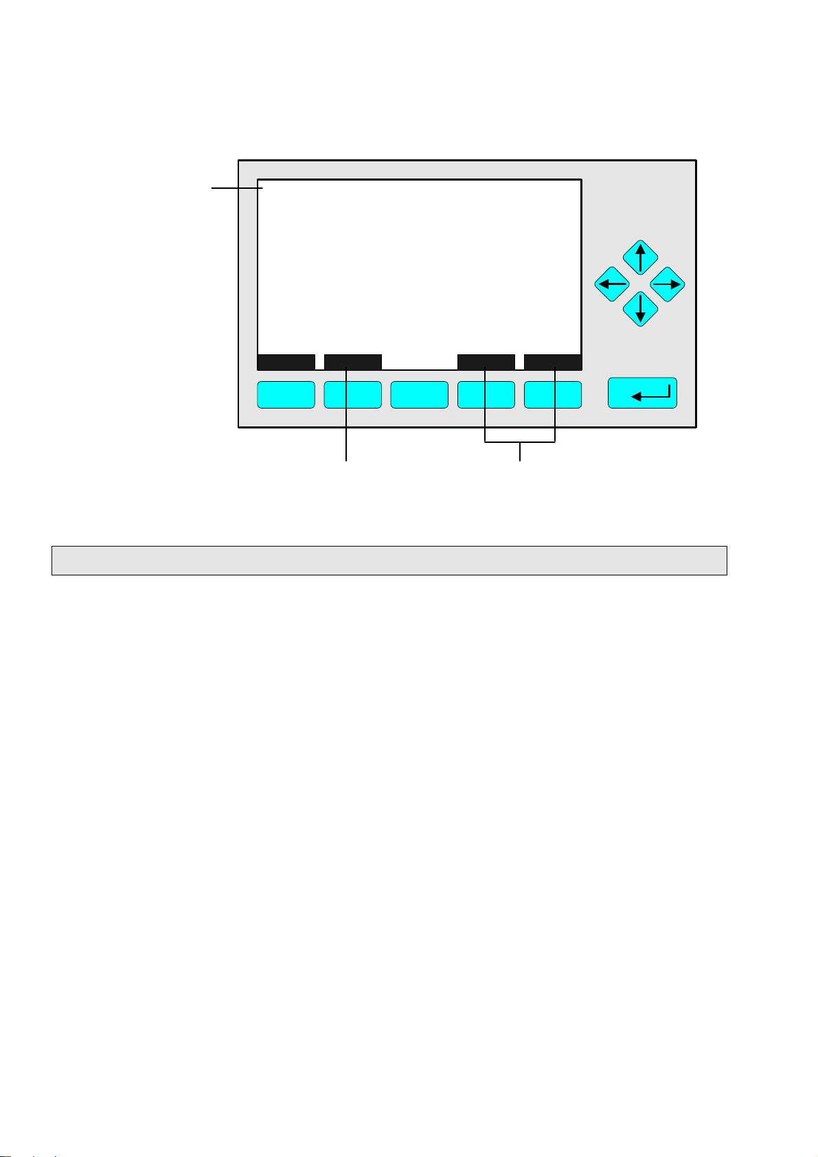
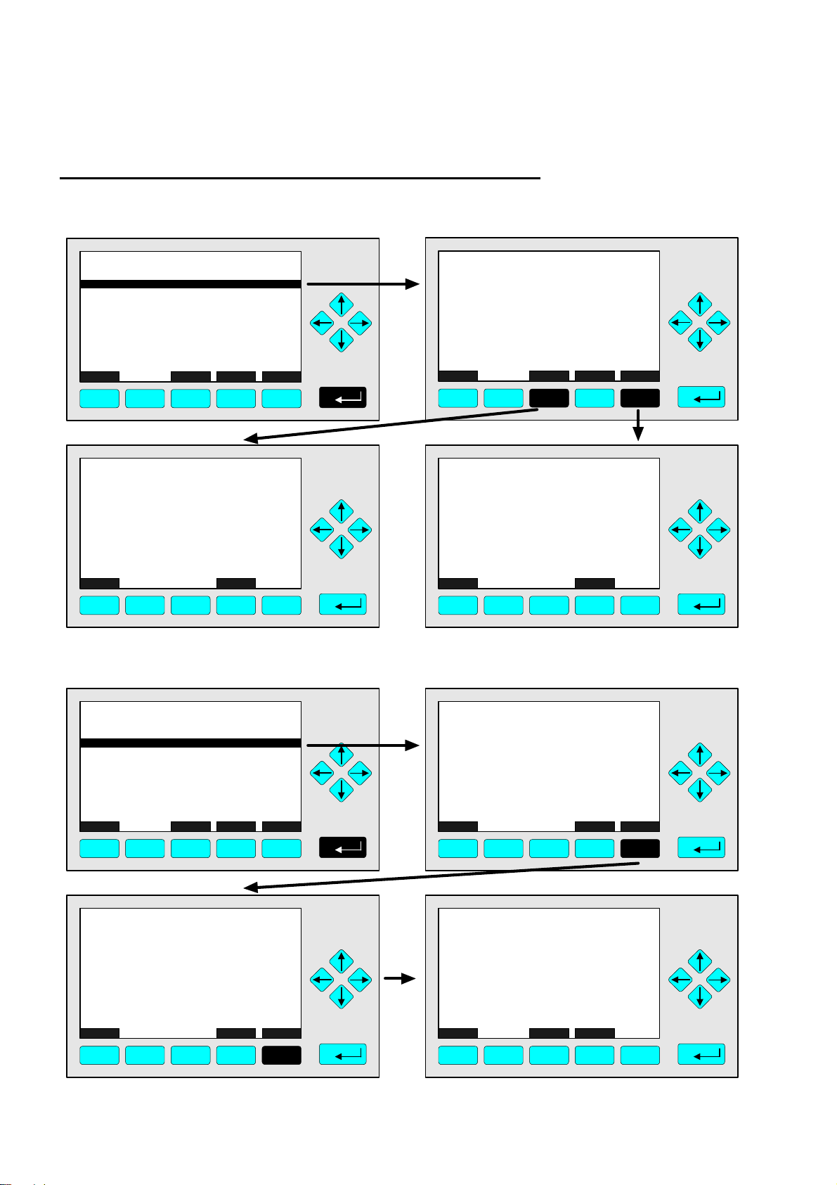
3.4 Lines and Softkey Functionality
Lines can be selected by the ↓↓ -key or the ↑↑ -key. The selected line is displayed white on
black. You have four different types of lines in the menu:
Menu line... / Menu Softkey...
♦ Line/Softkey lettering ending with three dots.
♦ You will go to a submenu/further menu by pressing the softkey resp. by pressing the
88 -key or the →→ -key in the menu line.
Function line / Function Softkey !
♦ Line/Softkey lettering ending with an exclamation-mark.
♦ You will start a function (e.g. calibration) by pressing the softkey resp. by pressing the
88 -key or the →→ -key in the function line.
Line of variables:
♦ Line ending with a colon.
♦ Display of module parameters (variables).
♦ Some parameters can be changed (e.g. begin of range), some parameters display only
a status (e.g. temperature) and cannot be changed. These variables will be displayed
below a line within the menu.
Text line
♦ Line without any punctuation marks.
♦ Only display of informations.
The following illustrations shall make plain the functionalities of lines and softkeys described above:
Menu Line
Function Lines
Lines of Variables
(These here cannot
be changed)
TAG
-- Analyzer Module Calibration --
Calibration procedure status...
Start zero calibration procedure !
Start span calibration procedure !
Time & Date: 12:50:55 June 16, 1998
Valve position: Samplegas
Expected zero gas: 0.00 ppm
Expected span gas: 50.00 ppm
Span gas name: Methane
Measure Status... Channel Back...
F1 F2 F3 F4 F5
37.50 ppm
Valves...
90003482(2) [NGA-e (MLT-Software 3.2.X)] 07/98
NGA 2000
3 - 3
Page 16
Text Line
TAG
-- Calibration Procedure Status --
Procedure status: Ready
Remaining procedure time: 0 s
Current/expected gas flow: Samplegas
Concentration in span gas units: 37.50 ppm
---------------------- Results ---------------------Last zero calibration: Success
Last span calibration: Success
Last zero calibration was: Fri 05-29-1998 13:32:06
Last span calibration was: Fri 05-29-1998 13:37:23
Successful zero+span calibrated ranges: 1+2+3+4
Measure Cancel ! Back... More...
F1 F2 F3 F4 F5
37.50 ppm
Function Softkey
Menu Softkeys
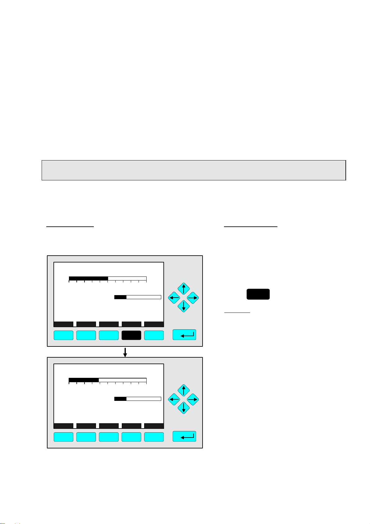
3.5 Important Functions of the Softkeys
Display
♦ Change from the single component display to the multi component display.
♦ F1 in the single component display.
Measure
♦ Change from all menus and submenus to the single component display of the channel
selected.
♦ F1.
Status (see section 4.1 p. 4-3!)
♦ Change to the menu "Analyzer Channel Status":
Display of the most important parameters and information about the status of the
current channel or module.
♦ If available: F2.
Main (see section 3.8 p. 3-7!)
♦ Change from the single component display to the main menu.
♦ F3 in the single component display.
Channel
♦ Scrolling through the channels in the same menu. In the main menu and the single
component display you can move among all channels of the connected analyzers and
analyzer modules. In the submenus you can only move among the channels of the
current analyzer or analyzer modules.
♦ If available: F3 (F4 in the single component display).
3 - 4
NGA 2000
90003482(2) [NGA-e (MLT-Software 3.2.X)] 07/98
Page 17

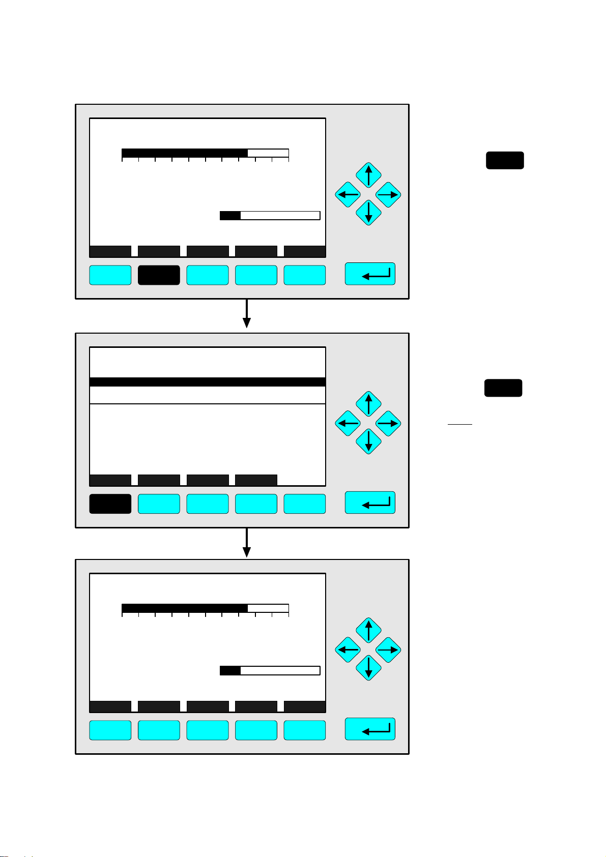
3 Startup and Operation, General Notes and Main Menu
Lock
♦ Lock of all three operation levels from the main menu, if a security code is activated in
the system configuration level (see section 6.3 p. 6-7).
♦ F4 in the main menu.
Calib (see section 4.4 p. 4-37 and 5.1.1 p. 5-15!)
♦ Change from the single component display to the menu "Analyzer module calibration".
♦ F5 in the single component display.
MFG Data (see section 3.8 p. 3-7/8!)
♦ Change from the main menu to the menu "Module Manufacturing Data":
Further submenus are available with informations about the control module and
analyzer module data, such as address of the manufacturer, serial number of the
modules or the software and hardware revisions.
♦ F5 in the main menu.
Back
♦ Moving back to the last menu page selected (Alternative: ←← -key) or
reset of a changed but not confirmed parameter to the former value.
♦ If available: F4 for moving back, F2 for reset.
More
♦ Changing to a further menu page.
♦ If available: F5.
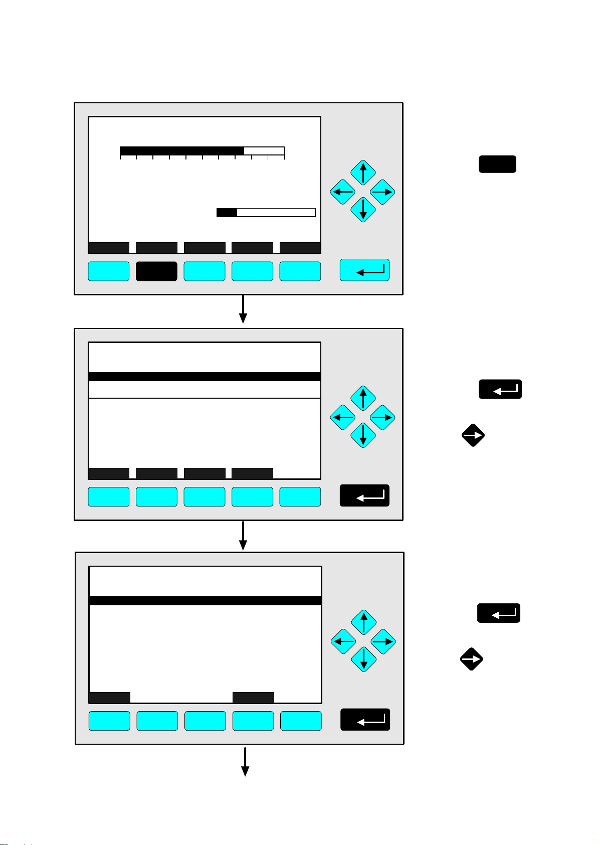
3.6 Entering/Changing of Variables
88 -key
♦ If you have already selected a line of variables (displayed white on black) and press the
88 -key, only the parameter will be selected and can be changed.
If you press the 88 -key again, the new value will be confirmed.
↑↑ -key / ↓↓ -key
♦ Function depends on the variable selected: - Changing the parameter values
- Scrolling among variables selected
- Changing of digits or characters
♦ Increasing or decreasing of numbers.
←← -key / →→ -key
♦ Selection of digits within a number.
♦ For some variables you can change the quantity of digits or characters.
90003482(2) [NGA-e (MLT-Software 3.2.X)] 07/98
NGA 2000
3 - 5
Page 18
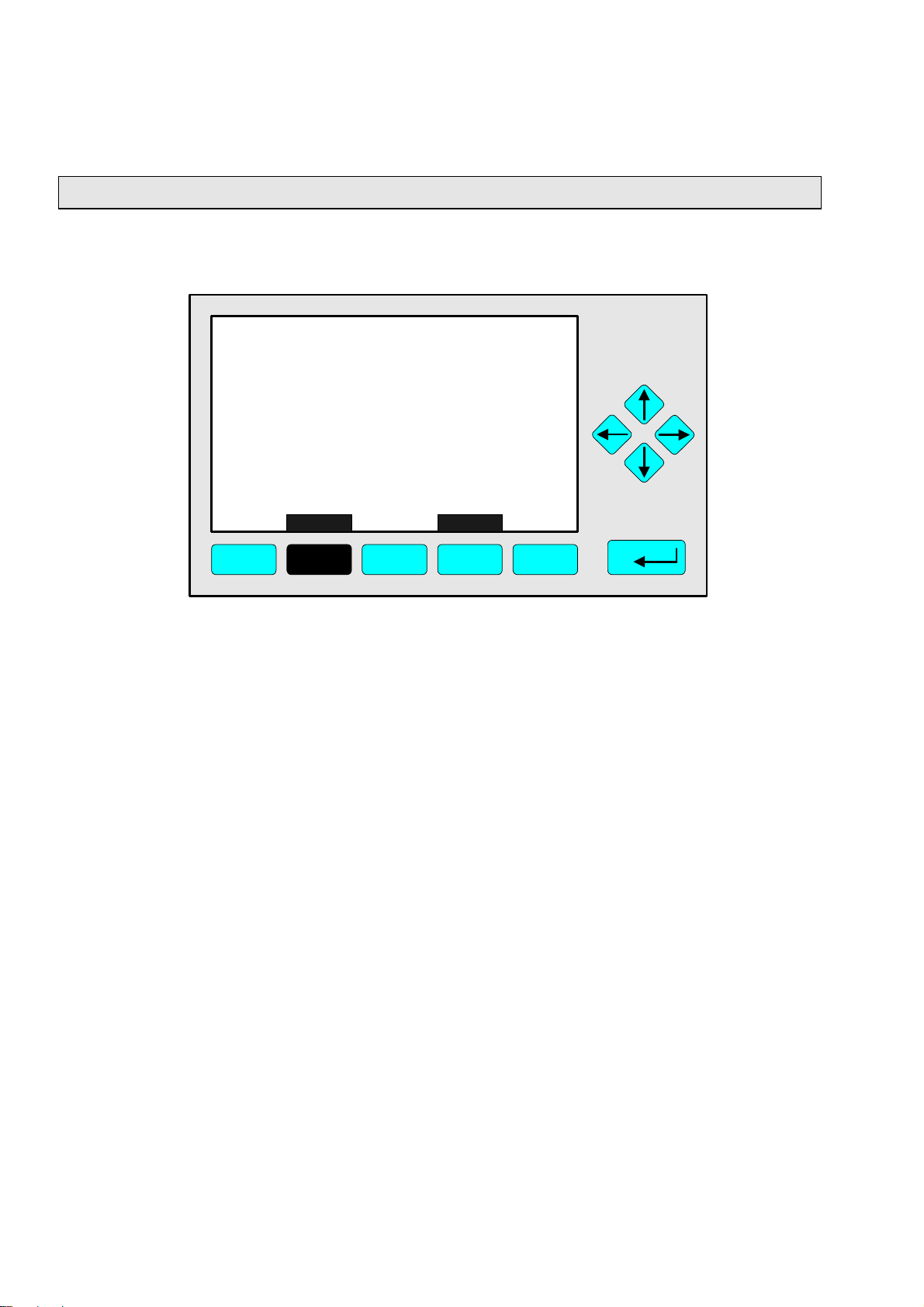
3.7 Starting a function
If you press the 88 -key or the →→ -key in a function line, you will be asked to confirm the
order in the following way:
TAG
-- Confirmation Required --
Do you really want to do this ??
Press "Yes" or "Back..."
Yes Back...
F1 F2 F3 F4 F5
37.50 ppm
♦ If you will press the F2 key, the function will start immediately.
♦ If you will press the F4 key, you will go back to the last menu page.
Note: If you don't want to be asked before the start of each function, you can configure it
in the menu "Measurement Display Configuration" in the expert configuration level (see
section 5.1.8 p. 5-49). Select "No" in the line "Display confirmation menus". Then, each
function will start directly after the order is done and no confirmation will be required.
3 - 6
NGA 2000
90003482(2) [NGA-e (MLT-Software 3.2.X)] 07/98
Page 19
3 Startup and Operation, General Notes and Main Menu
To setup see 6.2 p. 6-6
3.8 Main Menu
If you press the F3 key (Main...) or the →→ -key in any single component display, you
will change to the "Main Menu". From there you can change to all operating levels
of your MLT analyzer or analyzer module to set up and control the parameters of
measurement, calibration and data transfer !
Via the F5 key (MFG Data) you can change to several submenus, where you will find
a lot of important data about the control module (MLT analyzer or platform) and the
analyzer module, such as service address or serial number !
Ramifications from the Main Menu:
TAG
-- Main Menu --
Analyzer module calibration & basic controls...
Analyzer and I/O-module expert configuration...
System configuration and diagnostics...
Display controls...
Time & Date: 14:01:45 25 May 1998
System tag: Fisher-Rosemount
Measure Status... Channel Lock... MFG Data
F1 F2 F3 F4 F5
F1
F2
F3
Changing to the single component display of the
current channel
Changing to the menu "Analyzer Channel Status" of
the current channel
Scrolling through all channels of the connected
analyzers and analyzer modules
95.00 ppm
+
+
+
See chapter 4 !
See chapter 5 !
See chapter 6 !
See chapter 7 !
Factory Setting
Section 3.1 p. 3-1/2 !
Section 4.1 p. 4-3 !
See channel tag !
F4
F5
90003482(2) [NGA-e (MLT-Software 3.2.X)] 07/98
Lock of any operating level by security code
Changing to the menu "Module Manufacturing Data"
NGA 2000
+
+
Section 6.3 p. 6-7 !
See next pages !
3 - 7
Page 20
Ramifications from the menu "Module Manufacturing Data":
1. Control module data:
TAG
Control module data...
Analyzer module data...
Measure <<< Back... >>>
-- Module Manufacturing Data --
F1 F2 F3 F4 F5
TAG
(C) Copyright Fisher-Rosemount Analytical Inc., 1998
Manufactured by:
Rosemount Analytical Inc.
4125 East La Palma Avenue
Anaheim, CA 92807-1802 /USA
Tel: (714) 986-7600
FAX: (714) 577-8739
Measure Back...
F1 F2 F3 F4 F5
2. Analyzer module data:
95.00 ppm
95.00 ppm
TAG
(C) Copyright Fisher-Rosemount GmbH & Co, 1998
Manufactured by:
Fisher-Rosemount GmbH & Co
Industriestrasse 1
D-63594 Hasselroth / Germany
Tel. (+49) 6055 884-0
FAX. (+49) 6055 884-209
Measure Or... Back... More...
F1 F2 F4 F5
TAG
-- Control Module Version Information --
Serial number: CM 4711
Manufacturing date: 14.05.1998
Hardware revision: ACU02 R: 3.2.2
Software revision: 3.2.1/P001
Revision date: May 29 1998
Revision time: 12:35:00
Phrase dictionary version: P001/1
Language: English
Measure Back...
F3
95.00 ppm
95.00 ppm
F1 F2 F3 F4 F5
TAG
Control module data...
Analyzer module data...
Measure <<< Back... >>>
-- Module Manufacturing Data --
95.00 ppm
F1 F2 F3 F4 F5
TAG
-- Analyzer Module Version Information --
Serial number: AM 4712
Manufacturing date: 14.05.1998
Hardware revision: ACU02 R: 3.2.2
Software revision: 3.2.1 / P001
Revision date: May 29 1998
Revision time: 12:41:18
Measure Back...
95.00 ppm
More... Measure Back...
F1 F2 F3 F4 F5
TAG
(C) Copyright Fisher-Rosemount GmbH & Co, 1998
Manufactured by:
Fisher-Rosemount GmbH & Co
Industriestrasse 1
D-63594 Hasselroth / Germany
Tel. (+49) 6055 884-0
FAX. (+49) 6055 884-209
Measure Back... More...
95.00 ppm
F1 F2 F3 F4 F5
TAG
Measurement system: PSV-System
RAM-memory: 242748 Bytes
Local SIO module installed: Enabled
Serial interface adaptor: RS-232
Heater installed: No
Local DIO module installed: 2
Sensor system revision:
-- Hardware Configuration --
Channel
95.00 ppm
F1 F2 F3 F4 F5
3 - 8
NGA 2000
90003482(2) [NGA-e (MLT-Software 3.2.X)] 07/98
Page 21
4 Basic Controls and Analyzer Module Calibration
In the chapter "Basic Controls and Analyzer Module Calibration" the most important measurement and calibration functions of your MLT analyzer or analyzer module are described.
All steps are figured with detailed illustrations and operation instructions. In the left column
you can see display and keyboard of the NGA front panel. The keys you have to press are
illustrated in black. In the right column you can read the instructions and notes. All
instructions will begin with any single component display and will end with the corresponding single component display after the setups are done. So you can easily compare the
actual display of the analyzer or analyzer module with the illustrations of the manual.
Example: You want to change from the single component display of channel 1(CO2) to
the single component display of channel 2 (CO).
• Picture one shows the starting situation: single component display of CO
• Picture two shows the result you get if you press the F4 key (Channel):
single component display of CO.
Left column: Right column:
Display and keyboard Instructions and notes
MLT25/CH1/R2
2.50 %CO2
0 5.00
Maintenance-Requests: No
Any_Alarms: No
Operation: Ready
Display Status... Main... Channel Calib...
F1 F2 F3 F4 F5
MLT25/CH2/R2
95.00 ppm CO
Range: 2
0.0 100.0Temperature: 25.0 C
⇒ ⇒ Change to the single
component display
of another channel
F4
Press
Example:
Changing from
CO2 (Channel 1) to
CO (Channel 2)
⇒ ⇒ Next instruction
or step
.
2
0 250
Temperature: 25.0 C
Maintenance-Requests: No
Any_Alarms: No
Operation: Ready
Display Status... Main... Channel Calib...
F1 F2 F3 F4 F5
90003482(2) [NGA-e (MLT-Software 3.2.X)] 07/98
Range: 2
0.0 100.0
NGA 2000
4 - 1
Page 22

4 - 2
NGA 2000
90003482(2) [NGA-e (MLT-Software 3.2.X)] 07/98
Page 23
TAG
37.50 ppm CH4
0.00 50.00
Range: 1
4.1 Analyzer Channel Status
⇒ ⇒ Change to the
menu "Analyzer
Channel Status"
F2
Press
Failures: No
Maintenance-Requests: No
Temperature: 20.0 C
Operation: Ready
Display Status... Main... Channel Calib...
0.0 100.0
F1 F2 F3 F4 F5
TAG
-- Analyzer Channel Status --
Status details...
Operational settings...
Hours of operations: 164
Operation status: Ready
Events: No
Alarms: No
Failures: No
Maintenance requests: No
Function control/Service: No
Measure Channel Back...
RawMeas
37.50 ppm
In the menu "Analyzer
Channel Status" you can
find status informations
of the current channel.
Via the menu lines "Status
details..." and "Operational
settings..." you can change
to further submenus.
(see 4.1.1 p. 4-5...30 and
4.1.2 p. 4-31/32)
⇒ ⇒ Change to the
single component
display
F1
Press
Note:
Via the F2 key you can
change to submenus
containing the primary
and secondary raw
measurements.
F1 F2 F3 F4 F5
TAG
37.50 ppm CH4
0.00 50.00
Failures: No
Maintenance-Requests: No
Temperature: 20.0 C
Operation: Ready
Display Status... Main... Channel Calib...
F1 F2 F3 F4 F5
Range: 1
0.0 100.0
⇒ ⇒ Back in the single
component display
90003482(2) [NGA-e (MLT-Software 3.2.X)] 07/98
NGA 2000
4 - 3
Page 24

4 - 4
NGA 2000
90003482(2) [NGA-e (MLT-Software 3.2.X)] 07/98
Page 25
4.1.1 Analyzer Channel Status - Status Details
TAG
37.50 ppm CH4
Failures
⇒ ⇒ Change to the
menu "Analyzer
Channel Status"
0.00 50.00
Failures: No
Maintenance-Requests: No
Temperature: 20.0 C
Operation: Ready
Display Status... Main... Channel Calib...
Range: 1
0.0 100.0
F1 F2 F3 F4 F5
TAG
-- Analyzer Channel Status --
Status details...
Operational settings...
Hours of operations: 164
Operation status: Ready
Events: No
Alarms: No
Failures: No
Maintenance requests: No
Function control/Service: No
Measure Channel Back...
RawMeas
37.50 ppm
F2
Press
⇒ ⇒ Change to the
submenu "Status
Details"
Press
or
F1 F2 F3 F4 F5
TAG
-- Status Details --
Failures...
Maintenance requests...
Function controls...
Measurements/Alarms...
Events...
Acknowledge and clear failures !
Acknowledge and clear maintenance requests !
Acknowledge and clear function controls !
Measure Back...
37.50 ppm
F1 F2 F3 F4 F5
⇒ ⇒ Change to the "List
of Possible Failures
(page 1 of 2)"
Press
or
90003482(2) [NGA-e (MLT-Software 3.2.X)] 07/98
NGA 2000
4 - 5
Page 26
MLT25/CH2/R2
-- List of Possible Failures(1/2) --
One or more failures: No
Configuration replaced by factory setting: No
Chopper fail: No
Raw signal too high: No
Detector signal communication failed: No
Raw signal too low: No
(reserved)
(reserved)
Temperature measurement: No
Invalid pressure measurement: No
Measure Back... More...
37.50 ppm
F1 F2 F3 F4 F5
MLT25/CH2/R2
-- List of Possible Failures(2/2) --
External Input: No
Linearization underflow: No
Linearization overflow: No
37.50 ppm
⇒ ⇒ Change to the
second menu page
F5
Press
⇒ ⇒ Change to the
single component
display
F1
Press
Measure Back...
F1 F2 F3 F4 F5
TAG
37.50 ppm CH4
0.00 50.00
Failures: No
Maintenance-Requests: No
Temperature: 20.0 C
Operation: Ready
Display Status... Main... Channel Calib...
F1 F2 F3 F4 F5
Range: 1
0.0 100.0
⇒ ⇒ Back in the single
component display
of the current
channel
4 - 6
NGA 2000
90003482(2) [NGA-e (MLT-Software 3.2.X)] 07/98
Page 27
4.1.1 Analyzer Channel Status - Status Details
TAG
37.50 ppm CH4
Maintenance Requests
⇒ ⇒ Change to the
menu "Analyzer
Channel Status"
0.00 50.00
Failures: No
Maintenance-Requests: No
Temperature: 20.0 C
Operation: Ready
Display Status... Main... Channel Calib...
Range: 1
0.0 100.0
F1 F2 F3 F4 F5
TAG
-- Analyzer Channel Status --
Status details...
Operational settings...
Hours of operations: 164
Operation status: Ready
Events: No
Alarms: No
Failures: No
Maintenance requests: No
Function control/Service: No
Measure Channel Back...
RawMeas
37.50 ppm
F2
Press
⇒ ⇒ Change to the
submenu "Status
Details"
Press
or
F1 F2 F3 F4 F5
TAG
-- Status Details --
Failures...
Maintenance requests...
Function controls...
Measurements/Alarms...
Events...
Acknowledge and clear failures !
Acknowledge and clear maintenance requests !
Acknowledge and clear function controls !
Measure Back...
37.50 ppm
F1 F2 F3 F4 F5
⇒ ⇒ Change to the line
"Maintenance
requests..."
Press or
as often as necessary to
get the menu line
"Maintenance requests..."
white on black.
90003482(2) [NGA-e (MLT-Software 3.2.X)] 07/98
NGA 2000
4 - 7
Page 28
TAG
-- Status Details --
Failures...
Maintenance requests...
Function controls...
Measurements/Alarms...
Events...
Acknowledge and clear failures !
Acknowledge and clear maintenance requests !
Acknowledge and clear function controls !
37.50 ppm
⇒ ⇒ Change to the
"List of Possible
Maintenance
Requests
(page 1 of 2)"
Press
Measure Back...
F1 F2 F3 F4 F5
MLT25/CH2/R2
-- List of Possible Maintenance Requests(1/2) --
One or more maintenance requests: No
Too much hours of operation: No
Zero calibration - deviation too high: No
Span calibration - deviation too high: No
Measurement too noisy for zero calibration: No
Measurement too noisy for span calibration: No
Measure Back...
37.50 ppm
More...
F1 F2 F3 F4 F5
or
⇒ ⇒ Change to the
second menu page
F5
Press
MLT25/CH2/R2
-- List of Possible Maintenance Requests(2/2) --
External Input: No
Measure Back...
F1 F2 F3 F4 F5
4 - 8
37.50 ppm
NGA 2000
⇒ ⇒ Change to the
single component
display
F1
Press
90003482(2) [NGA-e (MLT-Software 3.2.X)] 07/98
Page 29
4.1.1 Analyzer Channel Status - Status Details
TAG
37.50 ppm CH4
Maintenance Requests
⇒ ⇒ Back in the single
component display
of the current
channel
0.00 50.00
Failures: No
Maintenance-Requests: No
Temperature: 20.0 C
Operation: Ready
Display Status... Main... Channel Calib...
F1 F2 F3 F4 F5
Range: 1
0.0 100.0
90003482(2) [NGA-e (MLT-Software 3.2.X)] 07/98
NGA 2000
4 - 9
Page 30

4 - 10
NGA 2000
90003482(2) [NGA-e (MLT-Software 3.2.X)] 07/98
Page 31

4.1.1 Analyzer Channel Status - Status Details
TAG
37.50 ppm CH4
Function Controls
⇒ ⇒ Change to the
menu "Analyzer
Channel Status"
0.00 50.00
Failures: No
Maintenance-Requests: No
Temperature: 20.0 C
Operation: Ready
Display Status... Main... Channel Calib...
Range: 1
0.0 100.0
F1 F2 F3 F4 F5
TAG
-- Analyzer Channel Status --
Status details...
Operational settings...
Hours of operations: 164
Operation status: Ready
Events: No
Alarms: No
Failures: No
Maintenance requests: No
Function control/Service: No
Measure Channel Back...
RawMeas
37.50 ppm
F2
Press
⇒ ⇒ Change to the
submenu "Status
Details"
Press
or
F1 F2 F3 F4 F5
TAG
-- Status Details --
Failures...
Maintenance requests...
Function controls...
Measurements/Alarms...
Events...
Acknowledge and clear failures !
Acknowledge and clear maintenance requests !
Acknowledge and clear function controls !
Measure Back...
37.50 ppm
F1 F2 F3 F4 F5
⇒ ⇒ Change to the line
"Function controls..."
Press or
as often as necessary
to get the menu line
"Function controls..."
white on black.
90003482(2) [NGA-e (MLT-Software 3.2.X)] 07/98
NGA 2000
4 - 11
Page 32

TAG
-- Status Details --
Failures...
Maintenance requests...
Function controls...
Measurements/Alarms...
Events...
Acknowledge and clear failures !
Acknowledge and clear maintenance requests !
Acknowledge and clear function controls !
Measure Back...
37.50 ppm
F1 F2 F3 F4 F5
MLT25/CH2/R2
-- List of Possible Function Controls(1/1) --
One or more function controls: No
Request from external input: No
Concentration raw signal simulation: No
No sample gas flowing: No
Calibration in progress: No
State - Warmup: No
State - Pause: No
State - Standby: No
Secondary measurement simulation: No
External input: No
Measure Back...
37.50 ppm
⇒ ⇒ Change to the
"List of Possible
Function Controls"
Press
or
⇒ ⇒ Change to the
single component
display
F1
Press
F1 F2 F3 F4 F5
TAG
37.50 ppm CH4
0.00 50.00
Failures: No
Maintenance-Requests: No
Temperature: 20.0 C
Operation: Ready
Display Status... Main... Channel Calib...
F1 F2 F3 F4 F5
Range: 1
0.0 100.0
⇒ ⇒ Back in the single
component display
of the current
channel
4 - 12
NGA 2000
90003482(2) [NGA-e (MLT-Software 3.2.X)] 07/98
Page 33

4.1.1 Analyzer Channel Status - Status Details
TAG
37.50 ppm CH4
Measurements/Alarms
⇒ ⇒ Change to the
menu "Analyzer
Channel Status"
0.00 50.00
Failures: No
Maintenance-Requests: No
Temperature: 20.0 C
Operation: Ready
Display Status... Main... Channel Calib...
Range: 1
0.0 100.0
F1 F2 F3 F4 F5
TAG
-- Analyzer Channel Status --
Status details...
Operational settings...
Hours of operations: 164
Operation status: Ready
Events: No
Alarms: No
Failures: No
Maintenance requests: No
Function control/Service: No
Measure Channel Back...
RawMeas
37.50 ppm
F2
Press
⇒ ⇒ Change to the
submenu "Status
Details"
Press
or
F1 F2 F3 F4 F5
TAG
-- Status Details --
Failures...
Maintenance requests...
Function controls...
Measurements/Alarms...
Events...
Acknowledge and clear failures !
Acknowledge and clear maintenance requests !
Acknowledge and clear function controls !
Measure Back...
37.50 ppm
F1 F2 F3 F4 F5
⇒ ⇒ Change to the line
"Measurements/
Alarms..."
Press or
as often as necessary
to get the menu line
"Measurements/Alarms..."
white on black.
90003482(2) [NGA-e (MLT-Software 3.2.X)] 07/98
NGA 2000
4 - 13
Page 34

TAG
-- Status Details --
Failures...
Maintenance requests...
Function controls...
Measurements/Alarms...
Events...
Acknowledge and clear failures !
Acknowledge and clear maintenance requests !
Acknowledge and clear function controls !
Measure Back...
37.50 ppm
F1 F2 F3 F4 F5
TAG
-- Measurements/Alarms --
Concentration...
Concentration average...
Flow...
Pressure...
Temperature...
Calculator-1...
Calculator-2...
Calculator-3...
Calculator-4...
Measure Back...
37.50 ppm
F1 F2 F3 F4 F5
⇒ ⇒ Change to the
submenu
"Measurements/
Alarms"
Press
or
⇒ ⇒ Change to the single
component display
F1
Press
Options:
• With the ↑↑ or the ↓↓ -key
you can change to each
line in the menu.
• Press the 88 -key in the
line selected to change to
the corresponding submenu: There you will find
the status of the four
alarms
Note: If the hardware of the
menu point selected is not
available, a corresponding
message will appear!
TAG
37.50 ppm CH4
0.00 50.00
Failures: No
Maintenance-Requests: No
Temperature: 20.0 C
Operation: Ready
Display Status... Main... Channel Calib...
F1 F2 F3 F4 F5
4 - 14
Range: 1
0.0 100.0
NGA 2000
⇒ ⇒ Back in the single
component display
of the current
channel
90003482(2) [NGA-e (MLT-Software 3.2.X)] 07/98
Page 35

4.1.1 Analyzer Channel Status - Status Details
TAG
37.50 ppm CH4
Events
⇒ ⇒ Change to the
menu "Analyzer
Channel Status"
0.00 50.00
Failures: No
Maintenance-Requests: No
Temperature: 20.0 C
Operation: Ready
Display Status... Main... Channel Calib...
Range: 1
0.0 100.0
F1 F2 F3 F4 F5
TAG
-- Analyzer Channel Status --
Status details...
Operational settings...
Hours of operations: 164
Operation status: Ready
Events: No
Alarms: No
Failures: No
Maintenance requests: No
Function control/Service: No
Measure Channel Back...
RawMeas
37.50 ppm
F2
Press
⇒ ⇒ Change to the
submenu "Status
Details"
Press
or
F1 F2 F3 F4 F5
TAG
-- Status Details --
Failures...
Maintenance requests...
Function controls...
Measurements/Alarms...
Events...
Acknowledge and clear failures !
Acknowledge and clear maintenance requests !
Acknowledge and clear function controls !
Measure Back...
37.50 ppm
F1 F2 F3 F4 F5
⇒ ⇒ Change to the line
"Events..."
Press or
as often as necessary
to get the menu line
"Events..." white on black.
90003482(2) [NGA-e (MLT-Software 3.2.X)] 07/98
NGA 2000
4 - 15
Page 36

TAG
-- Status Details --
Failures...
Maintenance requests...
Function controls...
Measurements/Alarms...
Events...
Acknowledge and clear failures !
Acknowledge and clear maintenance requests !
Acknowledge and clear function controls !
Measure Back...
37.50 ppm
F1 F2 F3 F4 F5
MLT25/CH2/R2
-- Analyzer Module Events (1/2) --
Failure: --.--.-Maintenance request: --.--.-Function control/Service: --.--.-Last configuration lost: --.--.-Concentration alarm: --.--.-Flow alarm: --.--.-Linearization underflow: --.--.-Linearization overflow: --.--.-Calculator alarms active: --.--.-Local analog output out of range: --.--.--
Measure Status... Channel Back... More...
37.50 ppm
⇒ ⇒ Change to the
submenu "Analyzer
Module Events
(page 1 of 2)"
Press
or
⇒ ⇒ Change to the
second menu page
F5
Press
Note:
If any event has happened,
you will find a report of date
and time in the corresponding
line of this menu.
F1 F2 F3 F4 F5
MLT25/CH2/R2
-- Analyzer Module Events (2/2) --
Zero calibration started: --.--.-Zero calibration finished: --.--.-Span calibration started: --.--.-Span calibration finished: --.--.-Concentration average alarm: --.--.-Temperature alarm: --.--.-Pressure alarm: --.--.-New linearization calculated: --.--.-Sensor calibration: --.--.--
Measure Status... Channel Back...
37.50 ppm
F1 F2 F3 F4 F5
⇒ ⇒ Change to the
single component
display
F1
Press
4 - 16
NGA 2000
90003482(2) [NGA-e (MLT-Software 3.2.X)] 07/98
Page 37

4.1.1 Analyzer Channel Status - Status Details
TAG
37.50 ppm CH4
Events
⇒ ⇒ Back to the single
component display
of the current
channel
0.00 50.00
Failures: No
Maintenance-Requests: No
Temperature: 20.0 C
Operation: Ready
Display Status... Main... Channel Calib...
F1 F2 F3 F4 F5
Range: 1
0.0 100.0
90003482(2) [NGA-e (MLT-Software 3.2.X)] 07/98
NGA 2000
4 - 17
Page 38

4 - 18
NGA 2000
90003482(2) [NGA-e (MLT-Software 3.2.X)] 07/98
Page 39

4.1.1 Analyzer Channel Status - Status Details
TAG
37.50 ppm CH4
Acknowledge and Clear Failures
⇒ ⇒ Change to the
menu "Analyzer
Channel Status"
0.00 50.00
Failures: Yes
Maintenance-Requests: No
Temperature: 20.0 C
Operation: Ready
Display Status... Main... Channel Calib...
Range: 1
0.0 100.0
F1 F2 F3 F4 F5
TAG
-- Analyzer Channel Status --
Status details...
Operational settings...
Hours of operations: 164
Operation status: Ready
Events: No
Alarms: No
Failures: No
Maintenance requests: No
Function control/Service: No
Measure Channel Back...
RawMeas
37.50 ppm
F2
Press
Notes:
If you have solved the
reasons for the failures
reported, you should start
this function.
The menu "List of Possible
Failures" will be ready for
new reports !
⇒ ⇒ Change to the
submenu "Status
Details"
Press
or
F1 F2 F3 F4 F5
TAG
-- Status Details --
Failures...
Maintenance requests...
Function controls...
Measurements/Alarms...
Events...
Acknowledge and clear failures !
Acknowledge and clear maintenance requests !
Acknowledge and clear function controls !
Measure Back...
37.50 ppm
F1 F2 F3 F4 F5
⇒ ⇒ Change to the line
"Acknowledge and
clear failures !"
Press or
as often as necessary
to get the menu line
"Acknowledge and clear
failures !" white on black.
90003482(2) [NGA-e (MLT-Software 3.2.X)] 07/98
NGA 2000
4 - 19
Page 40

TAG
-- Status Details --
Failures...
Maintenance requests...
Function controls...
Measurements/Alarms...
Events...
Acknowledge and clear failures !
Acknowledge and clear maintenance requests !
Acknowledge and clear function controls !
Measure Back...
37.50 ppm
F1 F2 F3 F4 F5
TAG
-- Confirmation Required --
Do you really want to do this ??
Press "Yes" or "Back..."
Yes Back...
37.50 ppm
⇒ ⇒ Start the function
Press
or
Note:
Starting this function here is
only possible, if it is enabled
in the menu "Acknowledgement of Status Reports"
(see 5.1.9 p. 5-52) !
⇒ ⇒ Confirm the order
F2
Press
to start the function
immediately.
Option:
Press the F4 key if you want
to cancel the order and go
back to the menu "Status
Details".
F1 F2 F3 F4 F5
TAG
- S U C C E S S -
- The selected function has been started/executed (Wait a moment...)
37.50 ppm
F1 F2 F3 F4 F5
⇒ ⇒ Confirmation
message of the
function start
appears
This message will be displayed after the function
has been started.
Then the display will jump
automatically to the menu
"Status Details".
4 - 20
NGA 2000
90003482(2) [NGA-e (MLT-Software 3.2.X)] 07/98
Page 41

4.1.1 Analyzer Channel Status - Status Details
TAG
-- Status Details --
Failures...
Maintenance requests...
Function controls...
Measurements/Alarms...
Events...
Acknowledge and clear failures !
Acknowledge and clear maintenance requests !
Acknowledge and clear function controls !
Measure Back...
F1 F2 F3 F4 F5
37.50 ppm
Acknowledge and Clear Failures
⇒ ⇒ Change to the
single component
display of the
channel selected
F1
Press
TAG
37.50 ppm CH4
0.00 50.00
Failures: No
Maintenance-Requests: No
Temperature: 20.0 C
Operation: Ready
Display Status... Main... Channel Calib...
F1 F2 F3 F4 F5
Range: 1
0.0 100.0
⇒ ⇒ Back to the single
component display
of the current
channel after
clearing of failures
90003482(2) [NGA-e (MLT-Software 3.2.X)] 07/98
NGA 2000
4 - 21
Page 42

4 - 22
NGA 2000
90003482(2) [NGA-e (MLT-Software 3.2.X)] 07/98
Page 43
4.1.1 Analyzer Channel Status - Status Details
TAG
37.50 ppm CH4
Acknowledge and Clear Maintenance Requests
⇒ ⇒ Change to the menu
"Analyzer Channel
Status"
0.00 50.00
Failures: No
Maintenance-Requests: Yes
Temperature: 20.0 C
Operation: Ready
Display Status... Main... Channel Calib...
Range: 1
0.0 100.0
F1 F2 F3 F4 F5
TAG
-- Analyzer Channel Status --
Status details...
Operational settings...
Hours of operations: 164
Operation status: Ready
Events: No
Alarms: No
Failures: No
Maintenance requests: No
Function control/Service: No
Measure Channel Back...
RawMeas
37.50 ppm
F2
Press
Note:
If you have solved the
reasons for the maintenance
requests reported, you
should start this function.
The menu "List of Possible
Maintenance Requests" will
be ready for new reports !
⇒ ⇒ Change to the
submenu "Status
Details"
Press
or
F1 F2 F3 F4 F5
TAG
-- Status Details --
Failures...
Maintenance requests...
Function controls...
Measurements/Alarms...
Events...
Acknowledge and clear failures !
Acknowledge and clear maintenance requests !
Acknowledge and clear function controls !
Measure Back...
37.50 ppm
F1 F2 F3 F4 F5
⇒ ⇒ Change to the line
"Acknowledge and
clear maintenance
requests !"
Press or
as often as necessary
to get the menu line
"Acknowledge and clear
maintenance requests !"
white on black.
90003482(2) [NGA-e (MlT-Software 3.2.X)] 07/98
NGA 2000
4 - 23
Page 44

TAG
-- Status Details --
Failures...
Maintenance requests...
Function controls...
Measurements/Alarms...
Events...
Acknowledge and clear failures !
Acknowledge and clear maintenance requests !
Acknowledge and clear function controls !
Measure Back...
37.50 ppm
F1 F2 F3 F4 F5
⇒ ⇒ Start the function
Press
or
Note:
Starting this function here is
only possible, if it is enabled
in the menu "Acknowledgement of Status Reports"
(see 5.1.9 p. 5-52) !
⇒ ⇒ Confirm the order
TAG
-- Confirmation Required --
Do you really want to do this ??
Press "Yes" or "Back..."
Yes Back...
37.50 ppm
F1 F2 F3 F4 F5
TAG
- S U C C E S S -
- The selected function has been started/executed (Wait a moment...)
37.50 ppm
F2
Press
to start the function
immediately.
Option:
Press the F4 key if you want
to cancel the order and go
back to the menu "Status
Details".
⇒ ⇒ Confirmation
message of the
function start
appears
This message will be displayed after the function
has been started.
Then the display will jump
automatically to the menu
"Status Details".
F1 F2 F3 F4 F5
4 - 24
NGA 2000
90003482(2) [NGA-e (MLT-Software 3.2.X)] 07/98
Page 45
4.1.1 Analyzer Channel Status - Status Details
TAG
-- Status Details --
Failures...
Maintenance requests...
Function controls...
Measurements/Alarms...
Events...
Acknowledge and clear failures !
Acknowledge and clear maintenance requests !
Acknowledge and clear function controls !
Measure Back...
F1 F2 F3 F4 F5
37.50 ppm
Acknowledge and Clear Maintenance Requests
⇒ ⇒ Change to the
single component
display of the
channel selected
F1
Press
TAG
37.50 ppm CH4
0.00 50.00
Failures: No
Maintenance-Requests: No
Temperature: 20.0 C
Operation: Ready
Display Status... Main... Channel Calib...
F1 F2 F3 F4 F5
Range: 1
0.0 100.0
⇒ ⇒ Back to the single
component display
of the current
channel after
clearing of
maintenance
requests
90003482(2) [NGA-e (MlT-Software 3.2.X)] 07/98
NGA 2000
4 - 25
Page 46

4 - 26
NGA 2000
90003482(2) [NGA-e (MLT-Software 3.2.X)] 07/98
Page 47

4.1.1 Analyzer Channel Status - Status Details
TAG
37.50 ppm CH4
Acknowledge and Clear Function Controls
⇒ ⇒ Change to the menu
"Analyzer Channel
Status"
0.00 50.00
Failures: No
Maintenance-Requests: No
Temperature: 20.0 C
Operation: Ready
Display Status... Main... Channel Calib...
Range: 1
0.0 100.0
F1 F2 F3 F4 F5
TAG
-- Analyzer Channel Status --
Status details...
Operational settings...
Hours of operations: 164
Operation status: Ready
Events: No
Alarms: No
Failures: No
Maintenance requests: No
Function control/Service: No
Measure Channel Back...
RawMeas
37.50 ppm
F2
Press
Notes:
If you have solved the
reasons for the function
controls reported, you
should start this function.
The menu "List of Possible
Function Controls" will be
ready for new reports !
⇒ ⇒ Change to the
submenu "Status
Details"
Press
or
F1 F2 F3 F4 F5
TAG
-- Status Details --
Failures...
Maintenance requests...
Function controls...
Measurements/Alarms...
Events...
Acknowledge and clear failures !
Acknowledge and clear maintenance requests !
Acknowledge and clear function controls !
Measure Back...
37.50 ppm
F1 F2 F3 F4 F5
⇒ ⇒ Change to the line
"Acknowledge
and clear function
controls !"
Press or
as often as necessary
to get the menu line
"Acknowledge and clear
function controls!" white
on black.
90003482(2) [NGA-e (MLT-Software 3.2.X)] 07/98
NGA 2000
4 - 27
Page 48

TAG
-- Status Details --
Failures...
Maintenance requests...
Function controls...
Measurements/Alarms...
Events...
Acknowledge and clear failures !
Acknowledge and clear maintenance requests !
Acknowledge and clear function controls !
Measure Back...
37.50 ppm
F1 F2 F3 F4 F5
TAG
-- Confirmation Required --
Do you really want to do this ??
Press "Yes" or "Back..."
Yes Back...
37.50 ppm
⇒ ⇒ Start the function
Press
or
Note:
Starting this function here is
only possible, if it is enabled
in the menu "Acknowledgement of Status Reports"
(see 5.1.9 p. 5-52) !
⇒ ⇒ Confirm the order
F2
Press
to start the function
immediately.
Option:
Press the F4 key if you want
to cancel the order and go
back to the menu "Status
Details".
F1 F2 F3 F4 F5
TAG
- S U C C E S S -
- The selected function has been started/executed (Wait a moment...)
37.50 ppm
F1 F2 F3 F4 F5
⇒ ⇒ Confirmation
message of the
function start
appears
This message will be displayed after the function
has been started.
Then the display will jump
automatically to the menu
"Status Details".
4 - 28
NGA 2000
90003482(2) [NGA-e (MLT-Software 3.2.X)] 07/98
Page 49

4.1.1 Analyzer Channel Status - Status Details
TAG
-- Status Details --
Failures...
Maintenance requests...
Function controls...
Measurements/Alarms...
Events...
Acknowledge and clear failures !
Acknowledge and clear maintenance requests !
Acknowledge and clear function controls !
Measure Back...
F1 F2 F3 F4 F5
37.50 ppm
Acknowledge and Clear Function Controls
⇒ ⇒ Change to the
single component
display of the
channel selected
F1
Press
TAG
37.50 ppm CH4
0.00 50.00
Failures: No
Maintenance-Requests: No
Temperature: 20.0 C
Operation: Ready
Display Status... Main... Channel Calib...
F1 F2 F3 F4 F5
Range: 1
0.0 100.0
⇒ ⇒ Back to the single
component display
of the current
channel after
clearing of function
controls
90003482(2) [NGA-e (MLT-Software 3.2.X)] 07/98
NGA 2000
4 - 29
Page 50

4 - 30
NGA 2000
90003482(2) [NGA-e (MLT-Software 3.2.X)] 07/98
Page 51

4.1.2 Analyzer Channel Status - Operational Settings
TAG
37.50 ppm CH4
⇒ ⇒ Change to the
menu "Analyzer
Channel Status"
0.00 50.00
Failures: No
Maintenance-Requests: No
Temperature: 20.0 C
Operation: Ready
Display Status... Main... Channel Calib...
Range: 1
0.0 100.0
F1 F2 F3 F4 F5
TAG
-- Analyzer Channel Status --
Status details...
Operational settings...
Hours of operations: 164
Operation status: Ready
Events: No
Alarms: No
Failures: No
Maintenance requests: No
Function control/Service: No
Measure Channel Back...
RawMeas
37.50 ppm
F2
Press
⇒ ⇒ Change to the line
"Operational
settings..."
Press once
to get the line
"Operational settings..."
white on black.
F1 F2 F3 F4 F5
TAG
-- Analyzer Channel Status --
Status details...
Operational settings...
Hours of operations: 164
Operation status: Ready
Events: No
Alarms: No
Failures: No
Maintenance requests: No
Function control/Service: No
Measure Channel Back...
RawMeas
37.50 ppm
F1 F2 F3 F4 F5
⇒ ⇒ Change to the
menu "Analyzer
Operation Settings"
Press
90003482(2) [NGA-e (MLT-Software 3.2.X)] 07/98
NGA 2000
4 - 31
Page 52

TAG
-- Analyzer Operation Settings --
Remote control: Enabled
Range change control: Manual
Range: 1
Range upper limit: 50.00 ppm
Span gas concentration: 50.00 ppm
t90-time: 2.00 s
Hours of operation: 164
Last re-start occured: 8:40:35 June 22, 1998
Actual zero gas concentration: 0.00 ppm
Auto-start procedures...
Measure Channel Back...
37.50 ppm
F1 F2 F3 F4 F5
TAG
-- Auto-Start Procedures --
Position in auto-start list: 1
Channel tag: Procedure type: Interval mode: Never
Start time: Start date: -
Time & Date: 16:03:25 June 22, 1998
Measure Back...
37.50 ppm
⇒ ⇒ Change to the
submenu "AutoStart Procedures"
Press
⇒ ⇒ Change to the
single component
display
Note:
In the menu
"Auto-Start Procedures"
you can control the status
of the three kinds of time
controlled calibrations.
(see 5.1.1 p. 5-12/13)
F1 F2 F3 F4 F5
TAG
37.50 ppm CH4
0.00 50.00
Failures: No
Maintenance-Requests: No
Temperature: 20.0 C
Operation: Ready
Display Status... Main... Channel Calib...
F1 F2 F3 F4 F5
Range: 1
0.0 100.0
⇒ ⇒ Back to the single
component display
of the current
channel
4 - 32
NGA 2000
90003482(2) [NGA-e (MLT-Software 3.2.X)] 07/98
Page 53

MLT25/CH1/R2
2.50 %CO2
4.2 Single Component Display
Change of Channel
⇒ ⇒ Change to the single
component display
of another channel
0 5.00
Maintenance-Requests: No
Any_Alarms: No
Operation: Ready
Display Status... Main... Channel Calib...
F1 F2 F3 F4 F5
MLT25/CH2/R2
Range: 2
0.0 100.0Temperature: 25.0 C
95.00 ppm CO
0 250
Temperature: 25.0 C
Maintenance-Requests: No
Any_Alarms: No
Operation: Ready
Range: 2
0.0 100.0
F4
Press
Example:
Changing from
CO2 (Channel 1) to
CO (Channel 2)
⇒ ⇒ Change back to the
single component
display of the
starting channel
F4
Press
as often
as necessary to get the
display of the channel
you want
Display Status... Main... Channel Calib...
F1 F2 F3 F4 F5
MLT25/CH1/R2
2.50 %CO2
0 5.00
Maintenance-Requests: No
Any_Alarms: No
Operation: Ready
Display Status... Main... Channel Calib...
F1 F2 F3 F4 F5
Range: 2
0.0 100.0Temperature: 25.0 C
Note:
You can reach any existing
channel by pressing the F4
key for several times.
⇒ ⇒ Single component
display of the
starting channel
appears
90003482(2) [NGA-e (MLT-Software 3.2.X)] 07/98
NGA 2000
4 - 33
Page 54

4 - 34
NGA 2000
90003482(2) [NGA-e (MLT-Software 3.2.X)] 07/98
Page 55

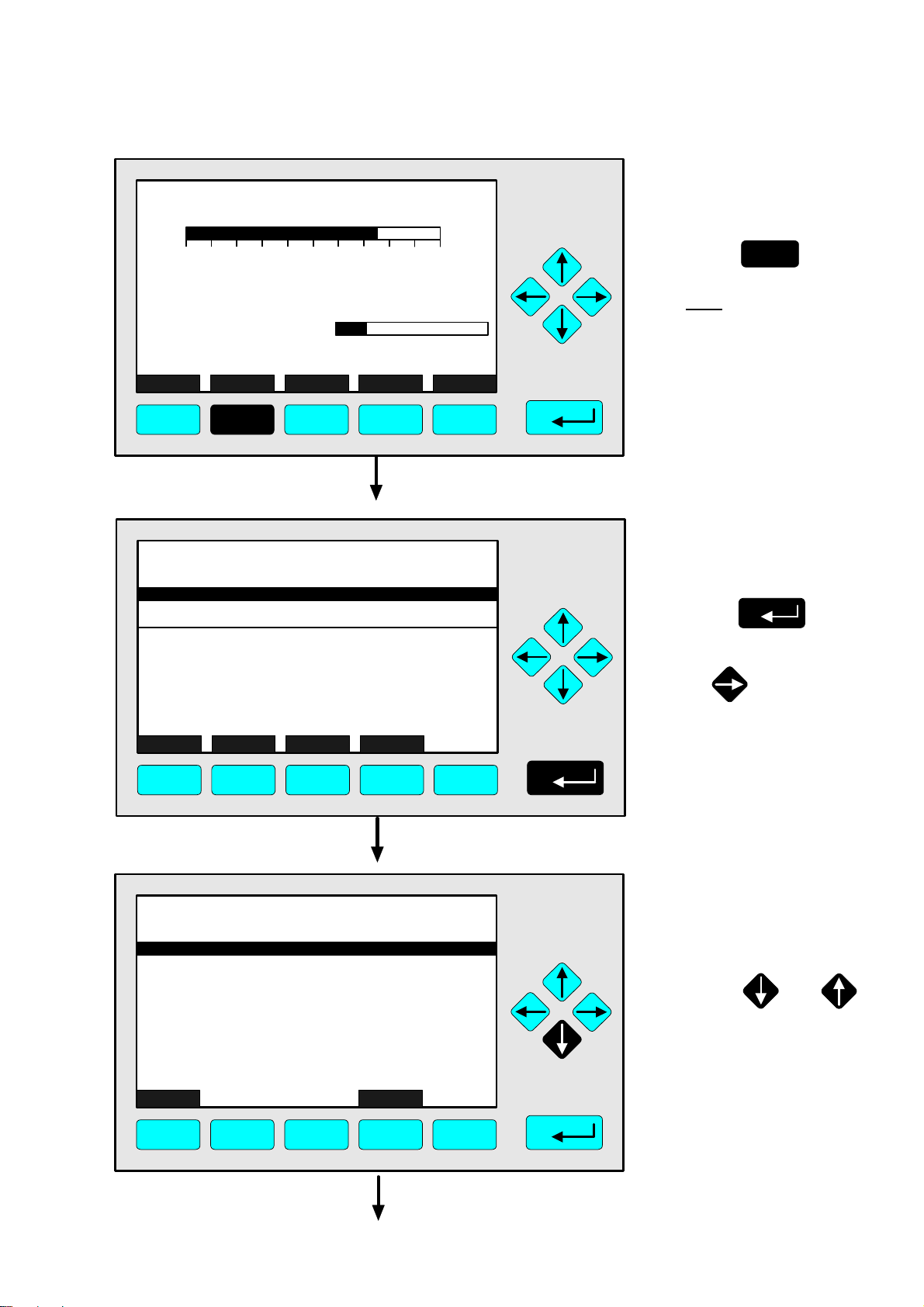
MLT25/CH1/R2
2.50 %CO2
4.3 Multi Component Display
Change of Channel
⇒ ⇒ Change to the
multi component display
0 5.00
Maintenance-Requests: No
Any_Alarms: No
Operation: Ready
Display Status... Main... Channel Calib...
Range: 2
0.0 100.0Temperature: 25.0 C
F1 F2 F3 F4 F5
2.50
95.00
333.0
150.0
20.00
Select Status... Tags Off
MLT25/CH1
%CO2
MLT25/CH2
ppm CO
MLT25/CH3
ppm SO2
MLT25/CH4
ppm NO
MLT25/CH5
%O2
2]
0.00
0.00 250.00
0.00 500.00
0.00 150.00
0.00 100.00
[
[2]
[2]
[2] F.S.
[2]
5.00
LCDReset
F1 F2 F3 F4 F5
F1
Press
Note:
You can change to the multi
component display from
each single component
display.
⇒ ⇒ Enable the "selecting
symbol": >
F1
Press
Notes:
• In each bargraph you will
find the begin and end of
range of the corresponding
channel. (F.S. = full scale)
• The number in parentheses
shows the number of the
selected range.
Option:
With the F3 key you can
fade out or in the tags.
or
2.50
95.00
333.0
150.0
20.00
Select Status... Tags Off
MLT25/CH1
%CO2
MLT25/CH2
ppm CO
MLT25/CH3
ppm SO2
MLT25/CH4
ppm NO
MLT25/CH5
%O2
0.00
0.00 250.00
0.00 500.00
0.00 150.00
0.00 100.00
F1 F2 F3 F4 F5
90003482(2) [NGA-e (MLT-Software 3.2.X)] 07/98
2]
[
[2]
[2]
[2] F.S.
[2]
5.00
LCDReset
NGA 2000
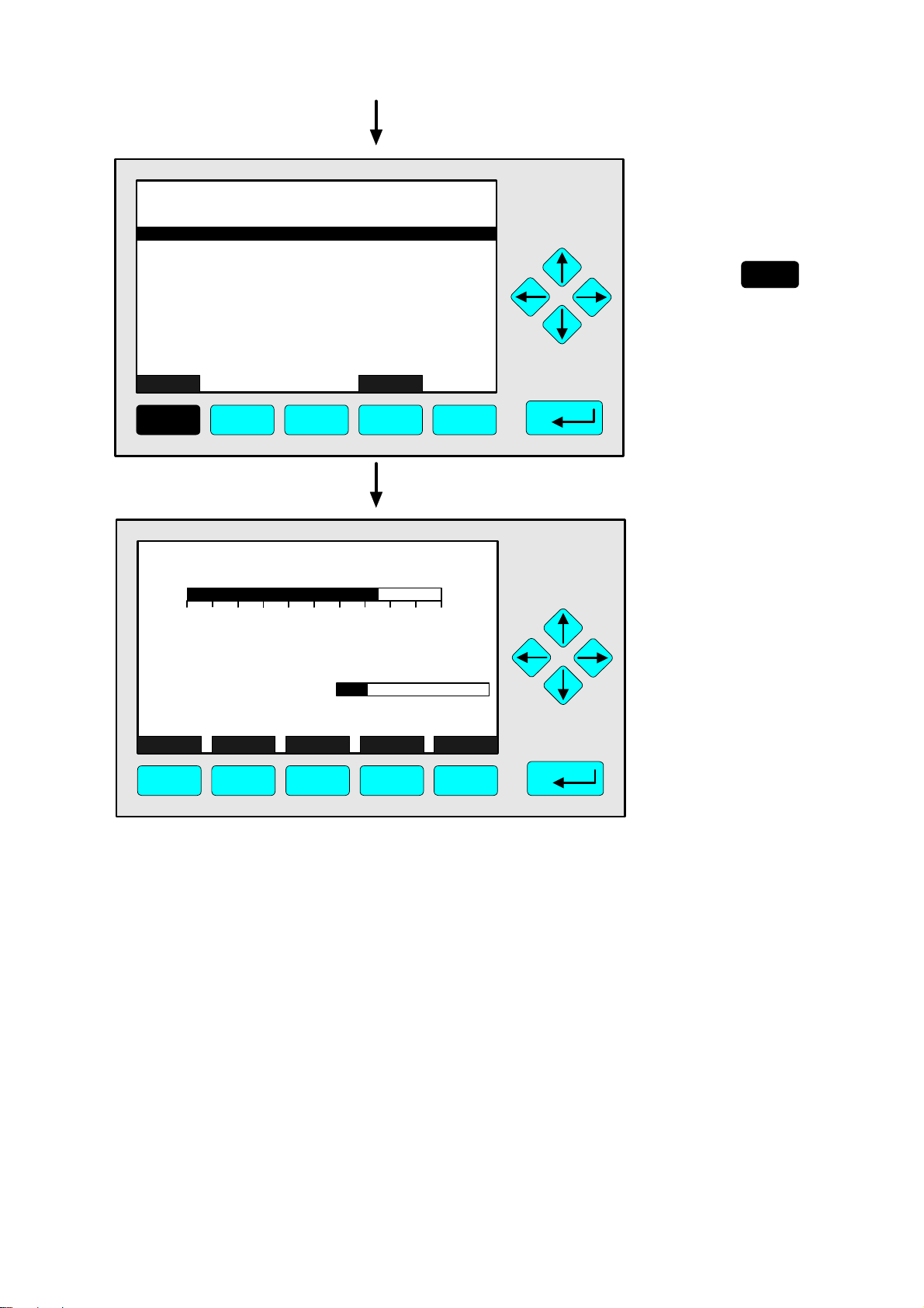
⇒ ⇒ Select any channel
Press or
as often as necessary to
put the > - mark into the
line you want to select.
Example:
Change from
CO2 (Channel 1) to
CO (Channel 2)
4 - 35
Page 56

2.50
95.00
333.0
150.0
20.00
Select Status... Tags Off
MLT25/CH1
%CO2
MLT25/CH2
ppm CO
MLT25/CH3
ppm SO2
MLT25/CH4
ppm NO
MLT25/CH5
%O2
2]
0.00
0.00 250.00
0.00 500.00
0.00 150.00
0.00 100.00
[
[2]
[2]
[2] F.S.
[2]
LCDReset
F1 F2 F3 F4 F5
MLT25/CH2/R2
95.00 ppm CO
5.00
⇒ ⇒ Change to the single
component display of
the channel selected
F1
Press
Note:
With the F5 key you can
enable the LCD-brightness
and contrast of the factory
settings (see also section 7).
⇒ ⇒ Single component
display of the
channel selected
appears
0 250
Temperature: 25.0 C
Maintenance-Requests: No
Any_Alarms: No
Operation: Ready
Display Status... Main... Channel Calib...
Range: 2
0.0 100.0
F1 F2 F3 F4 F5
4 - 36
NGA 2000
90003482(2) [NGA-e (MLT-Software 3.2.X)] 07/98
Page 57

TAG
37.50 ppm CH4
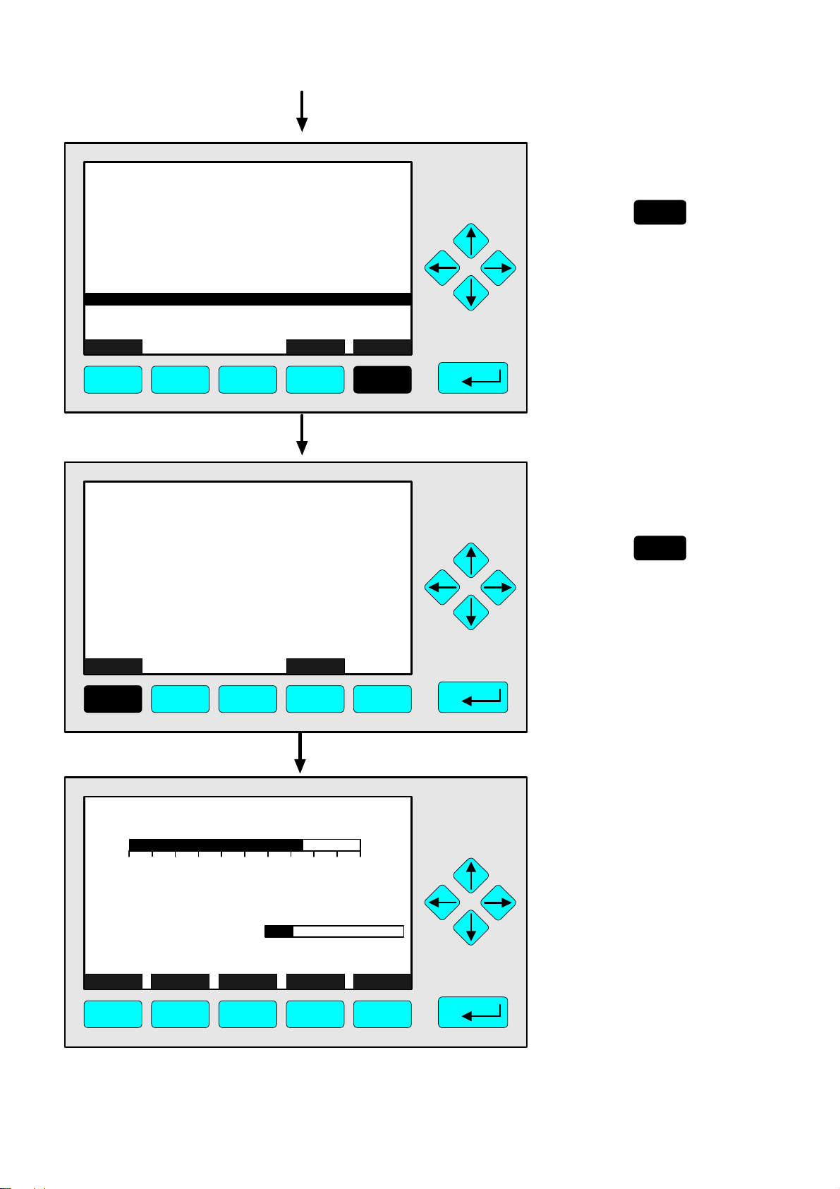
4.4 Calibration Procedure Status
⇒ ⇒ Change to the
menu "Analyzer
Module Calibration"
0.00 50.00
Failures: No
Maintenance-Requests: No
Temperature: 20.0 C
Operation: Ready
Display Status... Main... Channel Calib...
Range: 1
0.0 100.0
F1 F2 F3 F4 F5
TAG
-- Analyzer Module Calibration --
Calibration procedure status...
Start zero calibration procedure !
Start span calibration procedure !
Time & Date: 12:50:55 June 16, 1998
Valve position: Samplegas
Expected zero gas: 0.00 ppm
Expected span gas: 50.00 ppm
Span gas name: Methane
Measure Status... Channel Back...
37.50 ppm
Valves...
F1 F2 F3 F4 F5
F5
Press
⇒ ⇒ Change to the
menu "Calibration
Procedure Status"
Press
Options:
Via the F5 key you can
change to a submenu,
where you can close all
valves or set up each valve
separately with:
• zero gas or
• span gas or
• sample gas or
• test gas.
(See sections 4.7 to 4.11,
p. 4-47...)
TAG
-- Calibration Procedure Status --
Procedure status: Ready
Remaining procedure time: 0 s
Current/expected gas flow: Samplegas
Concentration in span gas units: 37.50 ppm
---------------------- Results ---------------------Last zero calibration: Success
Last span calibration: Success
Last zero calibration was: Fri 05-29-1998 13:32:06
Last span calibration was: Fri 05-29-1998 13:37:23
Successful zero+span calibrated ranges: 1+2+3+4
Measure Cancel ! Back... More...
F1 F2 F3 F4 F5
90003482(2) [NGA-e (MLT-Software 3.2.X)] 07/98
37.50 ppm
NGA 2000
⇒ ⇒ Change to the menu
page "Calibration
Deviations"
F5
Press
4 - 37
Page 58

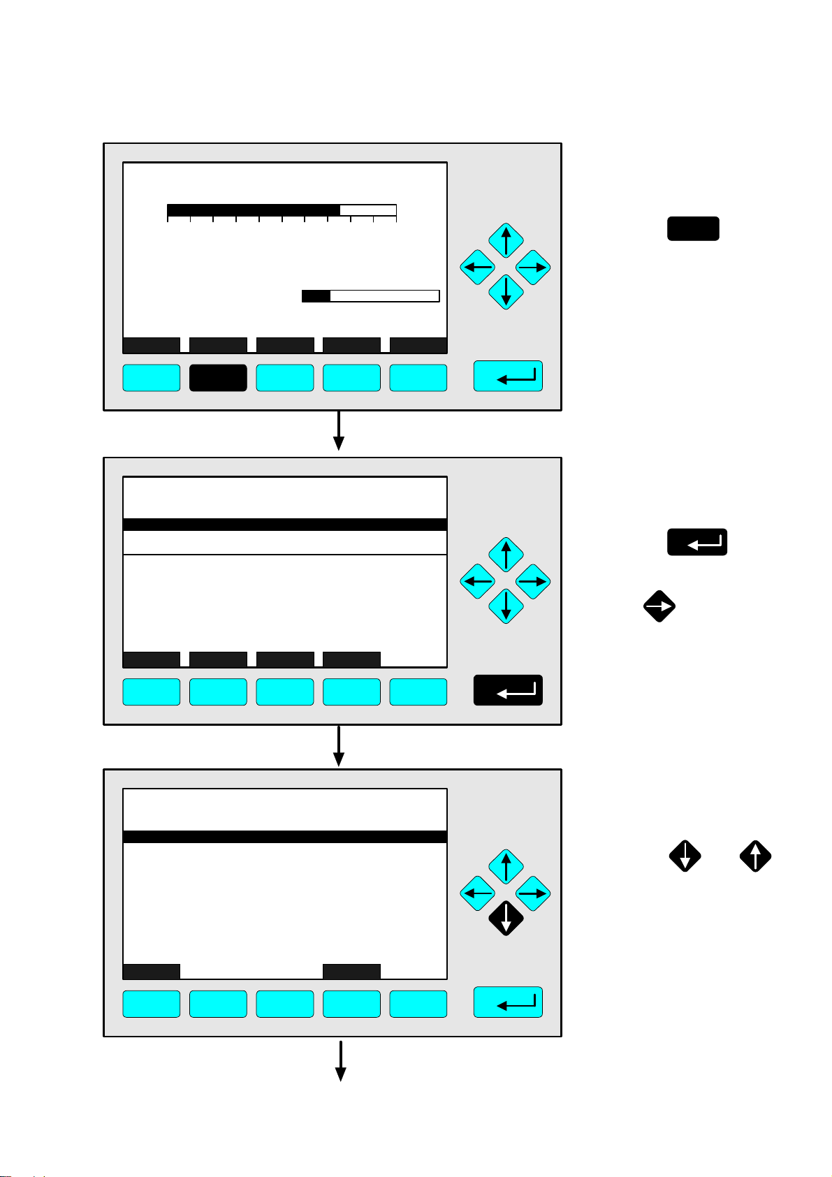
TAG
-- Calibration Deviations --
Deviation from zero: 0.34 ppm
Sum of zero deviations: 4.41 ppm
Deviation from span: 0.82 ppm
Sum of span deviations: 7.57 ppm
Measure Channel Back...
37.50 ppm
F1 F2 F3 F4 F5
TAG
37.50 ppm CH4
⇒ ⇒ Change to the single
component display of
the current channel
F1
Press
Options:
• With the F3 key you can
change to further available
channels to check their
"Calibration Deviations".
• With the F4 key you can
go back to the menu
"Calibration Procedure
Status".
⇒ ⇒ Back to the single
component display
0.00 50.00
Failures: No
Maintenance-Requests: No
Temperature: 20.0 C
Operation: Ready
Display Status... Main... Channel Calib...
Range: 1
0.0 100.0
F1 F2 F3 F4 F5
4 - 38
NGA 2000
90003482(2) [NGA-e (MLT-Software 3.2.X)] 07/98
Page 59

TAG
37.50 ppm CH4
0.00 50.00
Range: 1
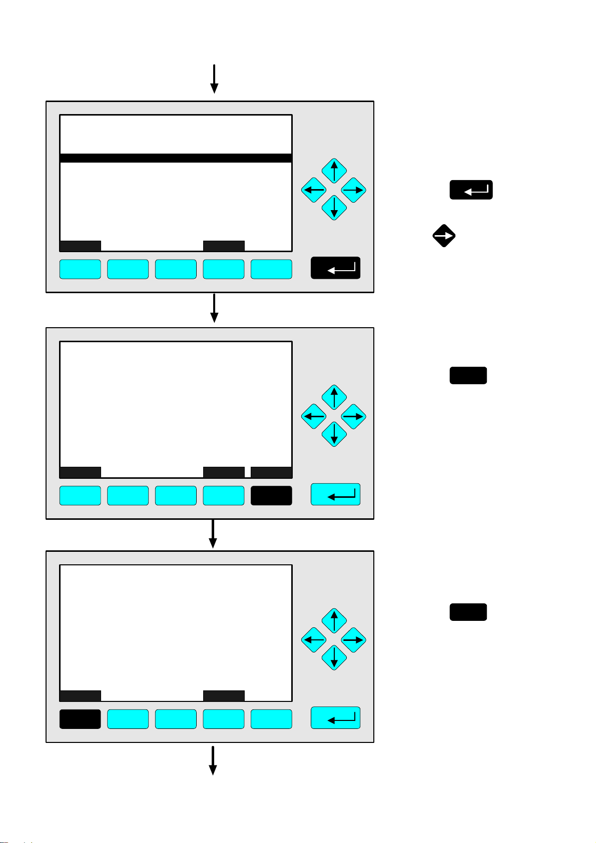
4.5 Zero Calibration
⇒ ⇒ Change to the
menu "Analyzer
Module Calibration"
F5
Press
Failures: No
Maintenance-Requests: No
Temperature: 20.0 C
Operation: Ready
Display Status... Main... Channel Calib...
0.0 100.0
F1 F2 F3 F4 F5
TAG
-- Analyzer Module Calibration --
Calibration procedure status...
Start zero calibration procedure !
Start span calibration procedure !
Time & Date: 12:50:55 June 16, 1998
Valve position: Samplegas
Expected zero gas: 0.00 ppm
Expected span gas: 50.00 ppm
Span gas name: Methane
Measure Status... Channel Back...
37.50 ppm
Valves...
Caution:
Before starting zero
calibration, realize that
zero gas is available !
(See also section 5.1.1,
p. 5-5... !)
Note:
The zeroing of all measurement ranges of the same
channel is running simultaneously.
⇒ ⇒ Change to the
line "Start zero
calibration
procedure !"
Press once to
get the line "Start zero
calibration procedure !"
white on black.
F1 F2 F3 F4 F5
TAG
-- Analyzer Module Calibration --
Calibration procedure status...
Start zero calibration procedure !
Start span calibration procedure !
Time & Date: 12:50:55 June 16, 1998
Valve position: Samplegas
Expected zero gas: 0.00 ppm
Expected span gas: 50.00 ppm
Span gas name: Methane
Measure Status... Channel Back...
37.50 ppm
Valves...
F1 F2 F3 F4 F5
⇒ ⇒ Start the zero
calibration
Press
or
90003482(2) [NGA-e (MLT-Software 3.2.X)] 07/98
NGA 2000
4 - 39
Page 60

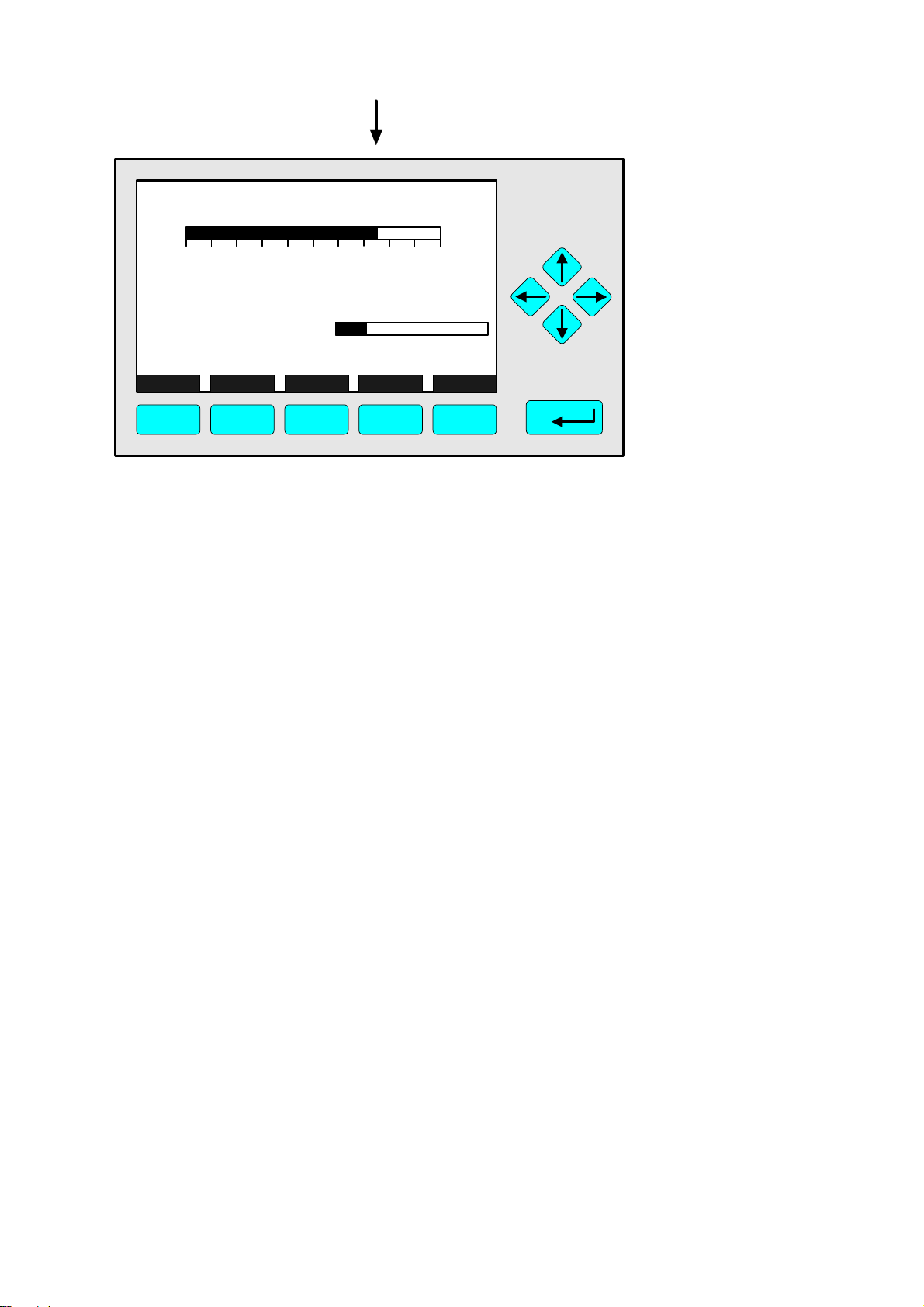
TAG
-- Confirmation Required --
Do you really want to do this ??
Press "Yes" or "Back..."
Yes Back...
37.50 ppm
F1 F2 F3 F4 F5
TAG
-- Calibration Procedure Status --
Procedure status: Purging1-Wait
Remaining procedure time: 8 s
Current/expected gas flow: Zerogas
Concentration in span gas units: 37.50 ppm
---------------------- Results ---------------------Last zero calibration: Success
Last span calibration: Success
Last zero calibration was: Fri 05-29-1998 13:32:06
Last span calibration was: Fri 05-29-1998 13:37:23
Successful zero+span calibrated ranges: 1+2+3+4
Measure Cancel ! Back... More...
37.50 ppm
F1 F2 F3 F4 F5
⇒ ⇒ Confirm the order for
zero calibration
F2
Press
to start
the zeroing immediately.
Option:
Press the F4 key if you want
to cancel the order.
Notes:
• The display of this message
depends on the setup in
the expert configurations.
(see 5.1.8 p. 5-49)
• The 3 following illustrations
show the displays you can
see after starting the
zeroing procedure.
⇒ ⇒ Zeroing:
1. Purging-Wait
Notes:
• The procedure time de-
pends on the parameters
entered for purge time
(see section 5.1.1 p. 5-9).
• The purge time must be
long enough to get a stable
signal before calibration.
• You can cancel the run-
ning calibration procedure
at any time with the F2 key.
TAG
-- Calibration Procedure Status --
Procedure status: Zeroing-Wait
Remaining procedure time: 97 s
Current/expected gas flow: Zerogas
Concentration in span gas units: 3.13 ppm
---------------------- Results ---------------------Last zero calibration: Success
Last span calibration: Success
Last zero calibration was: Fri 05-29-1998 13:32:06
Last span calibration was: Fri 05-29-1998 13:37:23
Successful zero+span calibrated ranges: 1+2+3+4
Measure Cancel ! Back... More...
F1 F2 F3 F4 F5
4 - 40
3.13 ppm
NGA 2000
⇒ ⇒ Zeroing:
2. Zeroing-Wait
Note:
The procedure time depends on the parameters
entered for stability time and
averaging time.
(see section 5.1.1 p. 5-9)
90003482(2) [NGA-e (MLT-Software 3.2.X)] 07/98
Page 61

TAG
-- Calibration Procedure Status --
Procedure status: Ready
Remaining procedure time: 0 s
Current/expected gas flow: Samplegas
Concentration in span gas units: 0.00 ppm
---------------------- Results ---------------------Last zero calibration: Success
Last span calibration: Success
Last zero calibration was: Mon 06-08-1998 09:21:34
Last span calibration was: Fri 05-29-1998 13:37:23
Successful zero+span calibrated ranges: 1+2+3+4
Measure Cancel ! Back... More...
0.00 ppm
F1 F2 F3 F4 F5
4.5 Zero Calibration
⇒ ⇒ Change to the
single component
display of the
current channel
F1
Press
Options:
• F4 key: Changing back
to the menu "Analyzer
Module Calibration".
• F5 key: Changing to
the menu "Calibration
Deviations".
TAG
0.00 ppm CH4
0.00 50.00
Failures: No
Maintenance-Requests: No
Temperature: 20.0 C
Operation: Ready
Display Status... Main... Channel Calib...
F1 F2 F3 F4 F5
Range: 1
0.0 100.0
⇒ ⇒ Single component
display appears after
zeroing is done
90003482(2) [NGA-e (MLT-Software 3.2.X)] 07/98
NGA 2000
4 - 41
Page 62

4 - 42
NGA 2000
90003482(2) [NGA-e (MLT-Software 3.2.X)] 07/98
Page 63
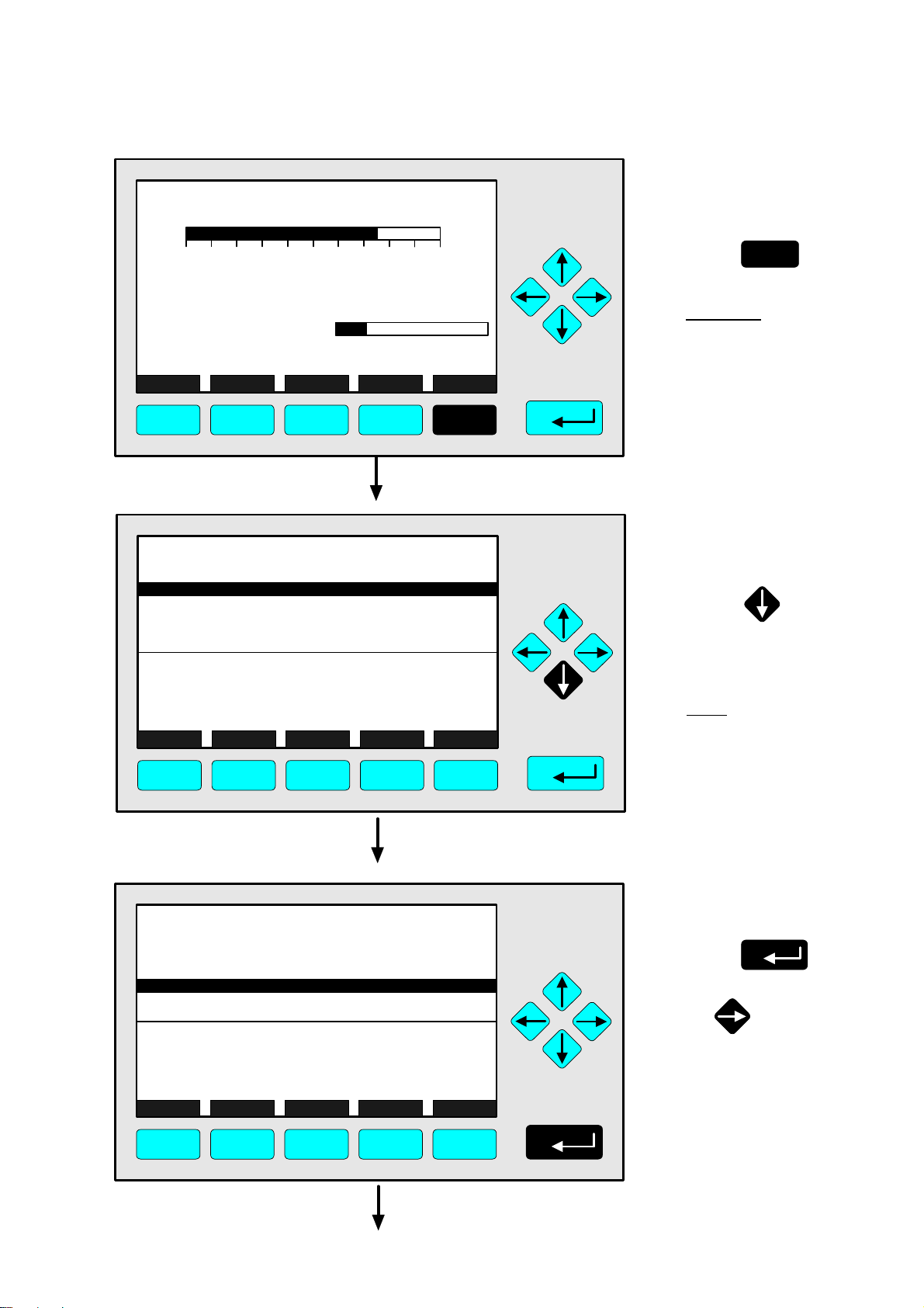
TAG
37.50 ppm CH4
4.6 Span Calibration
⇒ ⇒ Change to the
menu "Analyzer
Module Calibration"
0.00 50.00
Failures: No
Maintenance-Requests: No
Temperature: 20.0 C
Operation: Ready
Display Status... Main... Channel Calib...
Range: 1
0.0 100.0
F1 F2 F3 F4 F5
TAG
-- Analyzer Module Calibration --
Calibration procedure status...
Start zero calibration procedure !
Start span calibration procedure !
Time & Date: 12:50:55 June 16, 1998
Valve position: Samplegas
Expected zero gas: 0.00 ppm
Expected span gas: 50.00 ppm
Span gas name: Methane
Measure Status... Channel Back...
37.50 ppm
Valves...
F1 F2 F3 F4 F5
F5
Press
Caution:
Before starting span
calibration, realize that
spangas with correct
concentration is available !
(See also section 5.1.1,
p.5-5... !)
⇒ ⇒ Change to the line
"Start span calibration
procedure !"
Press twice to get
the line "Start span
calibration procedure !"
white on black.
Notes:
• Normally, all measurement
ranges of the same channel will be calibrated simultaneously.
• To calibrate seperately you
have to change the parameters (see 5.1.1 p. 5-11).
TAG
-- Analyzer Module Calibration --
Calibration procedure status...
Start zero calibration procedure !
Start span calibration procedure !
Time & Date: 12:50:55 June 16, 1998
Valve position: Samplegas
Expected zero gas: 0.00 ppm
Expected span gas: 50.00 ppm
Span gas name: Methane
Measure Status... Channel Back...
F1 F2 F3 F4 F5
90003482(2) [NGA-e (MLT-Software 3.2.X)] 07/98
37.50 ppm
Valves...
NGA 2000
⇒ ⇒ Start the
span calibration
Press
or
4 - 43
Page 64

TAG
-- Confirmation Required --
Do you really want to do this ??
Press "Yes" or "Back..."
Yes Back...
37.50 ppm
F1 F2 F3 F4 F5
TAG
-- Calibration Procedure Status --
Procedure status: Purging1-Wait
Remaining procedure time: 4 s
Current/expected gas flow: Spangas-1
Concentration in span gas units: 37.50 ppm
---------------------- Results ---------------------Last zero calibration: Success
Last span calibration: Success
Last zero calibration was: Mon 06-08-1998 09:21:34
Last span calibration was: Fri 05-29-1998 13:37:23
Successful zero+span calibrated ranges: 1+2+3+4
Measure Cancel ! Back... More...
37.50 ppm
F1 F2 F3 F4 F5
⇒ ⇒ Confirm the order for
span calibration
F2
Press
to start
the spanning immediately.
Option:
Press the F4 key if you want
to cancel the order.
Notes:
• The display of this message
depends on the setup in
the expert configurations.
(see 5.1.8 p. 5-49)
• The 3 following illustrations
show the displays you can
see after starting the
spanning procedure.
⇒ ⇒ Spanning:
1. Purging-Wait
Notes:
• The procedure time de-
pends on the parameters
entered for purge time
(see 5.1.1 p. 5-9).
• The purge time must be
long enough to get a stable
signal before calibration.
• You can cancel the run-
ning calibration procedure
at any time with the F2 key.
TAG
-- Calibration Procedure Status --
Procedure status: Spanning-Wait
Remaining procedure time: 108 s
Current/expected gas flow: Spangas-1
Concentration in span gas units: 43.57 ppm
---------------------- Results ---------------------Last zero calibration: Success
Last span calibration: Success
Last zero calibration was: Mon 06-08-1998 09:21:34
Last span calibration was: Fri 05-29-1998 13:37:23
Successful zero+span calibrated ranges: 1+2+3+4
Measure Cancel ! Back... More...
F1 F2 F3 F4 F5
4 - 44
43.57
NGA 2000
⇒ ⇒ Spanning:
2. Spanning-Wait
Note:
The procedure time depends on the parameters
entered for stability time and
averaging time.
(see 5.1.1 p.5-9)
90003482(2) [NGA-e (MLT-Software 3.2.X)] 07/98
Page 65

TAG
-- Calibration Procedure Status --
Procedure status: Ready
Remaining procedure time: 0 s
Current/expected gas flow: Samplegas
Concentration in span gas units: 50.00 ppm
---------------------- Results ---------------------Last zero calibration: Success
Last span calibration: Success
Last zero calibration was: Mon 06-08-1998 09:21:34
Last span calibration was: Mon 06-08-1998 09:28:13
Successful zero+span calibrated ranges: 1+2+3+4
Measure Cancel ! Back... More...
50.00 ppm
F1 F2 F3 F4 F5
4.6 Span Calibration
⇒ ⇒ Change to the
single component
display of the
current channel
F1
Press
Options:
• F4 key: Changing back
to the menu "Analyzer
Module Calibration".
• F5 key: Changing to
the menu "Calibration
Deviations".
TAG
50.00 ppm CH4
0.00 50.00
Failures: No
Maintenance-Requests: No
Temperature: 20.0 C
Operation: Ready
Display Status... Main... Channel Calib...
F1 F2 F3 F4 F5
Range: 1 F.S.
0.0 100.0
⇒ ⇒ Single component
display appears after
spanning is done
90003482(2) [NGA-e (MLT-Software 3.2.X)] 07/98
NGA 2000
4 - 45
Page 66

4 - 46
NGA 2000
90003482(2) [NGA-e (MLT-Software 3.2.X)] 07/98
Page 67

TAG
37.50 ppm CH4
4.7 Flow Zero Gas
⇒ ⇒ Change to the
menu "Analyzer
Module Calibration"
0.00 50.00
Failures: No
Maintenance-Requests: No
Temperature: 20.0 C
Operation: Ready
Display Status... Main... Channel Calib...
Range: 1
0.0 100.0
F1 F2 F3 F4 F5
TAG
-- Analyzer Module Calibration --
Calibration procedure status...
Start zero calibration procedure !
Start span calibration procedure !
Time & Date: 12:50:55 June 16, 1998
Valve position: Samplegas
Expected zero gas: 0.00 ppm
Expected span gas: 50.00 ppm
Span gas name: Methane
Measure Status... Channel Back...
37.50 ppm
Valves...
F5
Press
Caution:
Before starting zero gas
flow, realize that zero gas
is available !
(See also section 5.1.1,
p.5-5... !)
⇒ ⇒ Change to the
menu "Set Gas
Valves"
F5
Press
F1 F2 F3 F4 F5
TAG
-- Set Gas Valves --
Flow zero gas !
Flow span gas !
Flow sample gas !
Flow test gas !
Close all valves !
Valve position: Samplegas
Operation status: Ready
Measure Status... Channel Back...
37.50 ppm
F1 F2 F3 F4 F5
⇒ ⇒ Start the zero
gas flow
Press
or
Starting this function will
switch on the zero gas
valve as current gas valve.
90003482(2) [NGA-e (MLT-Software 3.2.X)] 07/98
NGA 2000
4 - 47
Page 68

TAG
-- Confirmation Required --
37.50 ppm
⇒ ⇒ Confirm the order to
flow zero gas
F2
Press
to start the zero
gas flow immediately.
Do you really want to do this ??
Press "Yes" or "Back..."
Yes Back...
F1 F2 F3 F4 F5
TAG
- S U C C E S S -
- The selected function has been started/executed (Wait a moment...)
37.50 ppm
Option:
Press the F4 key if you want
to cancel the order and go
back to the menu "Set Gas
Valves".
Note:
The display of this message
depends on the setup in the
expert configurations.
(see 5.1.8 p. 5-49)
⇒ ⇒ Confirmation
message of the
function start
appears
Note:
This message will be
displayed after the function
has been started. Then the
display will jump automatically to the menu "Set Gas
Valves".
F1 F2 F3 F4 F5
TAG
-- Set Gas Valves --
Flow zero gas !
Flow span gas !
Flow sample gas !
Flow test gas !
Close all valves !
Valve position: Zerogas
Operation status: Ready
Measure Status... Channel Back...
0.00 ppm
F1 F2 F3 F4 F5
⇒ ⇒ Change to the single
component display
of the current
channel
Options:
• Start the gasflow with
span gas, sample gas
or test gas.
• Close all valves.
• F3 key: Changing to
another available channel
to execute gas flow.
• F4 key: Go back to the
menu "Analyzer Module
Calibration" to start
zeroing or spanning.
4 - 48
NGA 2000
90003482(2) [NGA-e (MLT-Software 3.2.X)] 07/98
Page 69

TAG
0.00 ppm CH4
4.7 Flow Zero Gas
⇒ ⇒ Single component
display appears
during the zero gas
flow is running
0.00 50.00
Failures: No
Maintenance-Requests: No
Temperature: 20.0 C
Operation: Ready
Display Status... Main... Channel Calib...
F1 F2 F3 F4 F5
Range: 1
0.0 100.0
90003482(2) [NGA-e (MLT-Software 3.2.X)] 07/98
NGA 2000
4 - 49
Page 70

4 - 50
NGA 2000
90003482(2) [NGA-e (MLT-Software 3.2.X)] 07/98
Page 71

TAG
37.50 ppm CH4
4.8 Flow Span Gas
⇒ ⇒ Change to the
menu "Analyzer
Module Calibration"
0.00 50.00
Failures: No
Maintenance-Requests: No
Temperature: 20.0 C
Operation: Ready
Display Status... Main... Channel Calib...
Range: 1
0.0 100.0
F1 F2 F3 F4 F5
TAG
-- Analyzer Module Calibration --
Calibration procedure status...
Start zero calibration procedure !
Start span calibration procedure !
Time & Date: 12:50:55 June 16, 1998
Valve position: Samplegas
Expected zero gas: 0.00 ppm
Expected span gas: 50.00 ppm
Span gas name: Methane
Measure Status... Channel Back...
37.50 ppm
Valves...
F5
Press
Caution:
Before starting span gas
flow, realize that spangas
is available !
(See also section 5.1.1,
p. 5-5... !)
⇒ ⇒ Change to the
menu "Set Gas
Valves"
F5
Press
F1 F2 F3 F4 F5
TAG
-- Set Gas Valves --
Flow zero gas !
Flow span gas !
Flow sample gas !
Flow test gas !
Close all valves !
Valve position: Samplegas
Operation status: Ready
Measure Status... Channel Back...
37.50 ppm
F1 F2 F3 F4 F5
⇒ ⇒ Change to the line
"Flow span gas !"
Press once to
get the line "Flow span
gas !" white on black.
90003482(2) [NGA-e (MLT-Software 3.2.X)] 07/98
NGA 2000
4 - 51
Page 72

TAG
Flow zero gas !
Flow span gas !
Flow sample gas !
Flow test gas !
-- Set Gas Valves --
37.50 ppm
⇒ ⇒ Start the span
gas flow
Press
Close all valves !
Valve position: Samplegas
Operation status: Ready
Measure Status... Channel Back...
F1 F2 F3 F4 F5
TAG
-- Confirmation Required --
Do you really want to do this ??
Press "Yes" or "Back..."
Yes Back...
37.50 ppm
F1 F2 F3 F4 F5
or
Starting this function will
switch on the span gas
valve as current gas valve.
⇒ ⇒ Confirm the order to
flow span gas
F2
Press
to start the span
gas flow immediately.
Option:
Press the F4 key if you want
to cancel the order and go
back to the menu "Set Gas
Valves".
Note:
The display of this message
depends on the setup in the
expert configurations.
(see 5.1.8 p. 5-49)
TAG
- S U C C E S S -
- The selected function has been started/executed -
(Wait a moment...)
F1 F2 F3 F4 F5
4 - 52
37.50 ppm
NGA 2000
⇒ ⇒ Confirmation
message of the
function start
appears
Note:
This message will be
displayed after the function
has been started. Then the
display will jump automatically to the menu "Set Gas
Valves".
90003482(2) [NGA-e (MLT-Software 3.2.X)] 07/98
Page 73

TAG
-- Set Gas Valves --
Flow zero gas !
Flow span gas !
Flow sample gas !
Flow test gas !
Close all valves !
Valve position: Spangas-1
Operation status: Ready
Measure Status... Channel Back...
50.00 ppm
F1 F2 F3 F4 F5
4.8 Flow Span Gas
⇒ ⇒ Change to the single
component display
of the current
channel
Options:
• Start the gasflow with
zero gas, sample gas
or test gas.
• Close all valves.
• F3 key: Changing to
another available channel
to execute gas flow.
• F4 key: Go back to the
menu "Analyzer Module
Calibration" to start
zeroing or spanning.
TAG
50.00 ppm CH4
0.00 50.00
Failures: No
Maintenance-Requests: No
Temperature: 20.0 C
Operation: Ready
Display Status... Main... Channel Calib...
F1 F2 F3 F4 F5
Range: 1 F.S.
0.0 100.0
⇒ ⇒ Single component
display appears
during the span gas
flow is running
90003482(2) [NGA-e (MLT-Software 3.2.X)] 07/98
NGA 2000
4 - 53
Page 74

4 - 54
NGA 2000
90003482(2) [NGA-e (MLT-Software 3.2.X)] 07/98
Page 75

TAG
0.00 ppm CH4
4.9 Flow Sample Gas
⇒ ⇒ Change to the
menu "Analyzer
Module Calibration"
0.00 50.00
Failures: No
Maintenance-Requests: No
Temperature: 20.0 C
Operation: Ready
Display Status... Main... Channel Calib...
Range: 1
0.0 100.0
F1 F2 F3 F4 F5
TAG
-- Analyzer Module Calibration --
Calibration procedure status...
Start zero calibration procedure !
Start span calibration procedure !
Time & Date: 12:50:55 June 16, 1998
Valve position: Zerogas
Expected zero gas: 0.00 ppm
Expected span gas: 50.00 ppm
Span gas name: Methane
Measure Status... Channel Back...
0.00 ppm
Valves...
F5
Press
⇒ ⇒ Change to the
menu "Set Gas
Valves"
F5
Press
F1 F2 F3 F4 F5
TAG
-- Set Gas Valves --
Flow zero gas !
Flow span gas !
Flow sample gas !
Flow test gas !
Close all valves !
Valve position: Zerogas
Operation status: Ready
Measure Status... Channel Back...
0.00 ppm
F1 F2 F3 F4 F5
⇒ ⇒ Change to the line
"Flow sample gas !"
Press or
as often as necessary to
get the line "Flow sample
gas !" white on black.
90003482(2) [NGA-e (MLT-Software 3.2.X)] 07/98
NGA 2000
4 - 55
Page 76
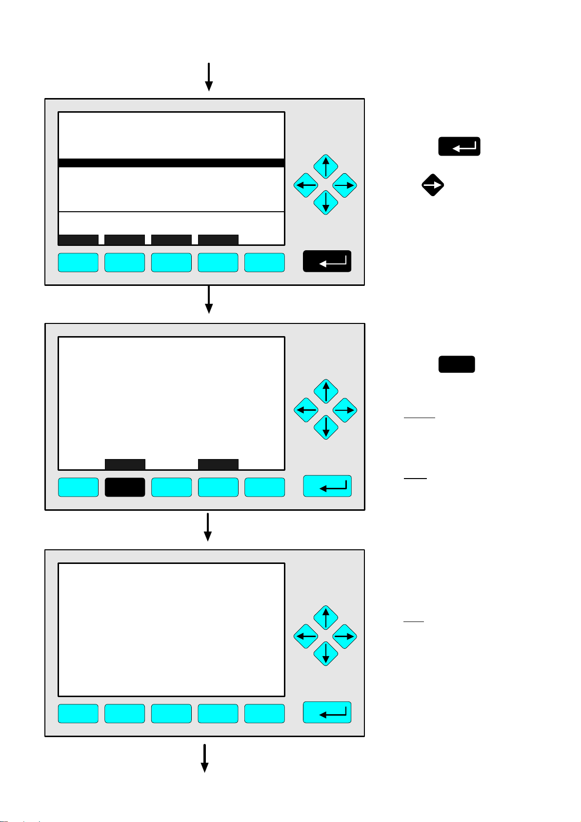
TAG
Flow zero gas !
Flow span gas !
Flow sample gas !
Flow test gas !
-- Set Gas Valves --
0.00 ppm
⇒ ⇒ Start the sample
gas flow
Press
Close all valves !
Valve position: Zerogas
Operation status: Ready
Measure Status... Channel Back...
F1 F2 F3 F4 F5
TAG
-- Confirmation Required --
Do you really want to do this ??
Press "Yes" or "Back..."
Yes Back...
0.00 ppm
F1 F2 F3 F4 F5
or
Starting this function will
switch on the sample gas
valve as current gas valve.
⇒ ⇒ Confirm the order to
flow sample gas
F2
Press
to start the sample
gas flow immediately.
Option:
Press the F4 key if you want
to cancel the order and go
back to the menu "Set Gas
Valves".
Note:
The display of this message
depends on the setup in the
expert configurations.
(see 5.1.8 p. 5-49)
TAG
- S U C C E S S -
- The selected function has been started/executed -
(Wait a moment...)
F1 F2 F3 F4 F5
4 - 56
0.00 ppm
NGA 2000
⇒ ⇒ Confirmation
message of the
function start
appears
Note:
This message will be
displayed after the function
has been started. Then the
display will jump automatically to the menu "Set Gas
Valves".
90003482(2) [NGA-e (MLT-Software 3.2.X)] 07/98
Page 77

TAG
-- Set Gas Valves --
Flow zero gas !
Flow span gas !
Flow sample gas !
Flow test gas !
Close all valves !
Valve position: Samplegas
Operation status: Ready
Measure Status... Channel Back...
37.50 ppm
F1 F2 F3 F4 F5
4.9 Flow Sample Gas
⇒ ⇒ Change to the single
component display
of the current
channel
Options:
• Start the gasflow with
zero gas, span gas or
test gas.
• Close all valves.
• F3 key: Changing to
another available channel
to execute gas flow.
• F4 key: Go back to the
menu "Analyzer Module
Calibration" to start
zeroing or spanning.
TAG
37.50 ppm CH4
0.00 50.00
Failures: No
Maintenance-Requests: No
Temperature: 20.0 C
Operation: Ready
Display Status... Main... Channel Calib...
F1 F2 F3 F4 F5
Range: 1
0.0 100.0
⇒ ⇒ Single component
display appears
during the sample
gas flow is running
90003482(2) [NGA-e (MLT-Software 3.2.X)] 07/98
NGA 2000
4 - 57
Page 78

4 - 58
NGA 2000
90003482(2) [NGA-e (MLT-Software 3.2.X)] 07/98
Page 79

TAG
37.50 ppm CH4
4.10 Flow Test Gas
⇒ ⇒ Change to the
menu "Analyzer
Module Calibration"
0.00 50.00
Failures: No
Maintenance-Requests: No
Temperature: 20.0 C
Operation: Ready
Display Status... Main... Channel Calib...
Range: 1
0.0 100.0
F1 F2 F3 F4 F5
TAG
-- Analyzer Module Calibration --
Calibration procedure status...
Start zero calibration procedure !
Start span calibration procedure !
Time & Date: 12:50:55 June 16, 1998
Valve position: Samplegas
Expected zero gas: 0.00 ppm
Expected span gas: 50.00 ppm
Span gas name: Methane
Measure Status... Channel Back...
37.50 ppm
Valves...
F5
Press
Starting this function will
switch an external valve and
flow the MLT with test gas.
⇒ ⇒ Change to the
menu "Set Gas
Valves"
F5
Press
F1 F2 F3 F4 F5
TAG
-- Set Gas Valves --
Flow zero gas !
Flow span gas !
Flow sample gas !
Flow test gas !
Close all valves !
Valve position: Samplegas
Operation status: Ready
Measure Status... Channel Back...
37.50 ppm
F1 F2 F3 F4 F5
⇒ ⇒ Change to the line
"Flow test gas !"
Press or
as often as necessary to
get the line "Flow test
gas !" white on black.
90003482(2) [NGA-e (MLT-Software 3.2.X)] 07/98
NGA 2000
4 - 59
Page 80

TAG
Flow zero gas !
Flow span gas !
Flow sample gas !
Flow test gas !
-- Set Gas Valves --
37.50 ppm
⇒ ⇒ Start the function to
flow test gas
Press
Close all valves !
Valve position: Samplegas
Operation status: Ready
Measure Status... Channel Back...
F1 F2 F3 F4 F5
TAG
-- Confirmation Required --
Do you really want to do this ??
Press "Yes" or "Back..."
Yes Back...
37.50 ppm
F1 F2 F3 F4 F5
or
⇒ ⇒ Confirm the order
to flow test gas
F2
Press
to start the test gas flow
immediately.
Option:
Press the F4 key if you want
to cancel the order and go
back to the menu "Set Gas
Valves".
Note:
The display of this message
depends on the setup in the
expert configurations.
(see 5.1.8 p. 5-49)
TAG
- S U C C E S S -
- The selected function has been started/executed -
(Wait a moment...)
F1 F2 F3 F4 F5
4 - 60
37.50 ppm
NGA 2000
⇒ ⇒ Confirmation
message of the
function start
appears
Note:
This message will be
displayed after the function
has been started. Then the
display will jump automatically to the menu "Set Gas
Valves".
90003482(2) [NGA-e (MLT-Software 3.2.X)] 07/98
Page 81

TAG
-- Set Gas Valves --
Flow zero gas !
Flow span gas !
Flow sample gas !
Flow test gas !
Close all valves !
Valve position: Testgas
Operation status: Ready
Measure Status... Channel Back...
20.00 ppm
F1 F2 F3 F4 F5
4.10 Flow Test Gas
⇒ ⇒ Change to the single
component display
of the current
channel
Options:
• Start the gasflow with
zero gas, span gas or
sample gas.
• Close all valves.
• F3 key: Changing to
another available channel
to execute gas flow.
• F4 key: Go back to the
menu "Analyzer Module
Calibration" to start
zeroing or spanning.
TAG
20.00 ppm CH4
0.00 50.00
Failures: No
Maintenance-Requests: No
Temperature: 20.0 C
Operation: Ready
Display Status... Main... Channel Calib...
F1 F2 F3 F4 F5
Range: 1
0.0 100.0
⇒ ⇒ Single component
display appears
during the test gas
flow is running
90003482(2) [NGA-e (MLT-Software 3.2.X)] 07/98
NGA 2000
4 - 61
Page 82

4 - 62
NGA 2000
90003482(2) [NGA-e (MLT-Software 3.2.X)] 07/98
Page 83

TAG
37.50 ppm CH4
4.11 Close all Valves
⇒ ⇒ Change to the
menu "Analyzer
Module Calibration"
0.00 50.00
Failures: No
Maintenance-Requests: No
Temperature: 20.0 C
Operation: Ready
Display Status... Main... Channel Calib...
Range: 1
0.0 100.0
F1 F2 F3 F4 F5
TAG
-- Analyzer Module Calibration --
Calibration procedure status...
Start zero calibration procedure !
Start span calibration procedure !
Time & Date: 12:50:55 June 16, 1998
Valve position: Samplegas
Expected zero gas: 0.00 ppm
Expected span gas: 50.00 ppm
Span gas name: Methane
Measure Status... Channel Back...
37.50 ppm
Valves...
F5
Press
⇒ ⇒ Change to the
menu "Set Gas
Valves"
F5
Press
F1 F2 F3 F4 F5
TAG
-- Set Gas Valves --
Flow zero gas !
Flow span gas !
Flow sample gas !
Flow test gas !
Close all valves !
Valve position: Samplegas
Operation status: Ready
Measure Status... Channel Back...
37.50 ppm
F1 F2 F3 F4 F5
⇒ ⇒ Change to the line
"Close all valves !"
Press or
as often as necessary to
get the line "Close all
valves !" white on black.
90003482(2) [NGA-e (MLT-Software 3.2.X)] 07/98
NGA 2000
4 - 63
Page 84

TAG
Flow zero gas !
Flow span gas !
Flow sample gas !
Flow test gas !
-- Set Gas Valves --
37.50 ppm
⇒ ⇒ Start the function to
close all valves
Press
Close all valves !
Valve position: Samplegas
Operation status: Ready
Measure Status... Channel Back...
F1 F2 F3 F4 F5
TAG
-- Confirmation Required --
Do you really want to do this ??
Press "Yes" or "Back..."
Yes Back...
37.50 ppm
F1 F2 F3 F4 F5
or
⇒ ⇒ Confirm the order
to close all valves
F2
Press
to close all valves
immediately.
Option:
Press the F4 key if you want
to cancel the order and go
back to the menu "Set Gas
Valves".
Note:
The display of this message
depends on the setup in the
expert configurations.
(see 5.1.8 p. 5-49)
TAG
- S U C C E S S -
- The selected function has been started/executed -
(Wait a moment...)
F1 F2 F3 F4 F5
4 - 64
37.50 ppm
NGA 2000
⇒ ⇒ Confirmation
message of the
function start
appears
Note:
This message will be
displayed after the function
has been started. Then the
display will jump automatically to the menu "Set Gas
Valves".
90003482(2) [NGA-e (MLT-Software 3.2.X)] 07/98
Page 85

TAG
-- Set Gas Valves --
Flow zero gas !
Flow span gas !
Flow sample gas !
Flow test gas !
Close all valves !
Valve position: AllClosed
Operation status: Ready
Measure Status... Channel Back...
37.50 ppm
F1 F2 F3 F4 F5
4.11 Close all Valves
⇒ ⇒ Change to the single
component display
of the current
channel
Options:
• Start the gasflow with
zero gas, span gas,
sample gas or test gas.
• F3 key: Changing to
another available channel
to execute gas flow.
• F4 key: Go back to the
menu "Analyzer Module
Calibration" to start
zeroing or spanning.
TAG
37.50 ppm CH4
0.00 50.00
Failures: No
Maintenance-Requests: No
Temperature: 20.0 C
Operation: Ready
Display Status... Main... Channel Calib...
F1 F2 F3 F4 F5
Range: 1
0.0 100.0
⇒ ⇒ Single component
display appears in
the standby mode:
All valves are closed
Note:
After the valves are closed
you can start again the
measurement with the "Flow
sample gas" order (see 4.9).
90003482(2) [NGA-e (MLT-Software 3.2.X)] 07/98
NGA 2000
4 - 65
Page 86

4 - 66
NGA 2000
90003482(2) [NGA-e (MLT-Software 3.2.X)] 07/98
Page 87

5 Analyzer and I/O-Module Expert Configuration
If you press the 88 -key or the →→ -key in the line "Analyzer and I/O-module expert
configuration..." of the "Main Menu", you will change to the following display:
TAG
-- Expert Module Configuration --
Analyzer module controls...
I/O module controls...
Analyzer module setup...
I/O module setup...
Measure Channel Back...
F1 F2 F3 F4 F5
37.50 ppm
From the menu "Expert Module Configuration" you can change to several submenus to
set up parameters for the measurement and calibration of your analyzer and analyzer
module. Besides you can set up the configuration for auxiliary modules. Which part of
these menus are important for you depends on the configuration of your NGA 2000
system.
In the following table you will find a short overview about the contents of the menus:
Menu Important Contents Section/Page
Analyzer module controls... ⇒ See "Analyzer module setup" and note below!
I/O module controls...
⇒ Configuration of the SIO and of the DIO's
installed in a platform or
∗ 5.2
p. 83 - 98
in an MLT analyzer (auxiliary I/O's)
Analyzer module setup...
⇒ Measurement set up and control
⇒ Calibration set up and control
⇒ Configuration of the SIO and of the DIO's
∗ 5.1
p. 3 - 82
installed in the MLT analyzer module
(Local SIO/DIO)
⇒ Programmable logic control (PLC)
⇒ Programmable calculators
I/O module setup...
⇒ Set up for micro processor controlled
∗ 5.3 / p. 99
auxiliary I/O modules
Note:
All submenus of "Analyzer module controls..." are the same like those of "Analyzer module
setup...", if you use an MLT analyzer or analyzer module (resp. TFID analyzer or analyzer
module)! If your analyzer is not such a type, the submenus of "Analyzer module
controls..." and "Analyzer module setup..." will look different, partially. Look at the
corresponding software manuals.
90003482(2) [NGA-e (MLT-Software 3.2.X)] 07/98
NGA 2000
5 - 1
Page 88

Structure of chapter five:
At the begin of any chapter you will find the way to a certain submenu of the MLT software
starting from the line "Analyzer and I/O-module expert configuration" in the "Main Menu".
The way will be described with the software catchwords, that you have to enter one after
another to reach the corresponding submenu. At the end of the catchword listing you will
find the illustration of the LCD screen. After that you can read the set up instructions and
explanations. Sometimes the illustration will be completed by sketches or further menu
pictures.
Example: You will set up the calibration parameters for the calibration procedure of the
analyzer module.
Main Menu — Analyzer and I/O-module expert configuration
↓↓
Analyzer module setup
↓↓
Calibration parameters
↓↓
Calibration procedure setup
↓↓
TAG
-- Calibration Procedure Setup --
Purge time: 10 s
Procedure times-out after: 120 s
Analog output during calibration: Tracking
Span ranges: Together
Valve position: Samplegas
Stability time: 30 s
Averaging time: 5 s
Measure Channel Back...
F1 F2 F3 F4 F5
In the menu "Calibration Procedure Setup" you can set up the parameters for the calibration procedure of the zeroing and spanning ...
95.00 ppm
Further explanations and instructions will follow !
5 - 2
NGA 2000
90003482(2) [NGA-e (MLT-Software 3.2.X)] 07/98
Page 89

5.1 Analyzer Module Setup
Main Menu — Analyzer and I/O-module expert configuration
↓↓
Analyzer module setup
↓↓
TAG
-- Analyzer Module Setup and Controls (1/3) --
Calibration parameters...
Alarm parameters...
Range parameters...
Cross interference compensation...
Linearization...
Programmable logic control (PLC)...
Programmable calculator...
Measurement display configuration...
Acknowledgement of status reports...
Concentration measurement parameters...
Measure ManData Channel Back... More...
95.00 ppm
F1 F2 F3 F4 F5
TAG
-- Analyzer Module Setup and Controls (2/3) --
Peak measurement...
Differential measurement...
Gasflow setup...
Pressure compensation...
Flow measurement...
Temperature measurement...
Loading/saving configuration parameters...
Inputs and outputs...
Delay and average...
Special functions...
Measure Channel Back...
95.00 ppm
More...
F1 F2 F3 F4 F5
TAG
-- Analyzer Module Setup and Controls (3/3) --
AK-protocol communication...
Measure Back...
F1 F2 F3 F4 F5
90003482(2) [NGA-e (MLT-Software 3.2.X)] 07/98
NGA 2000
95.00 ppm
5 - 3
Page 90
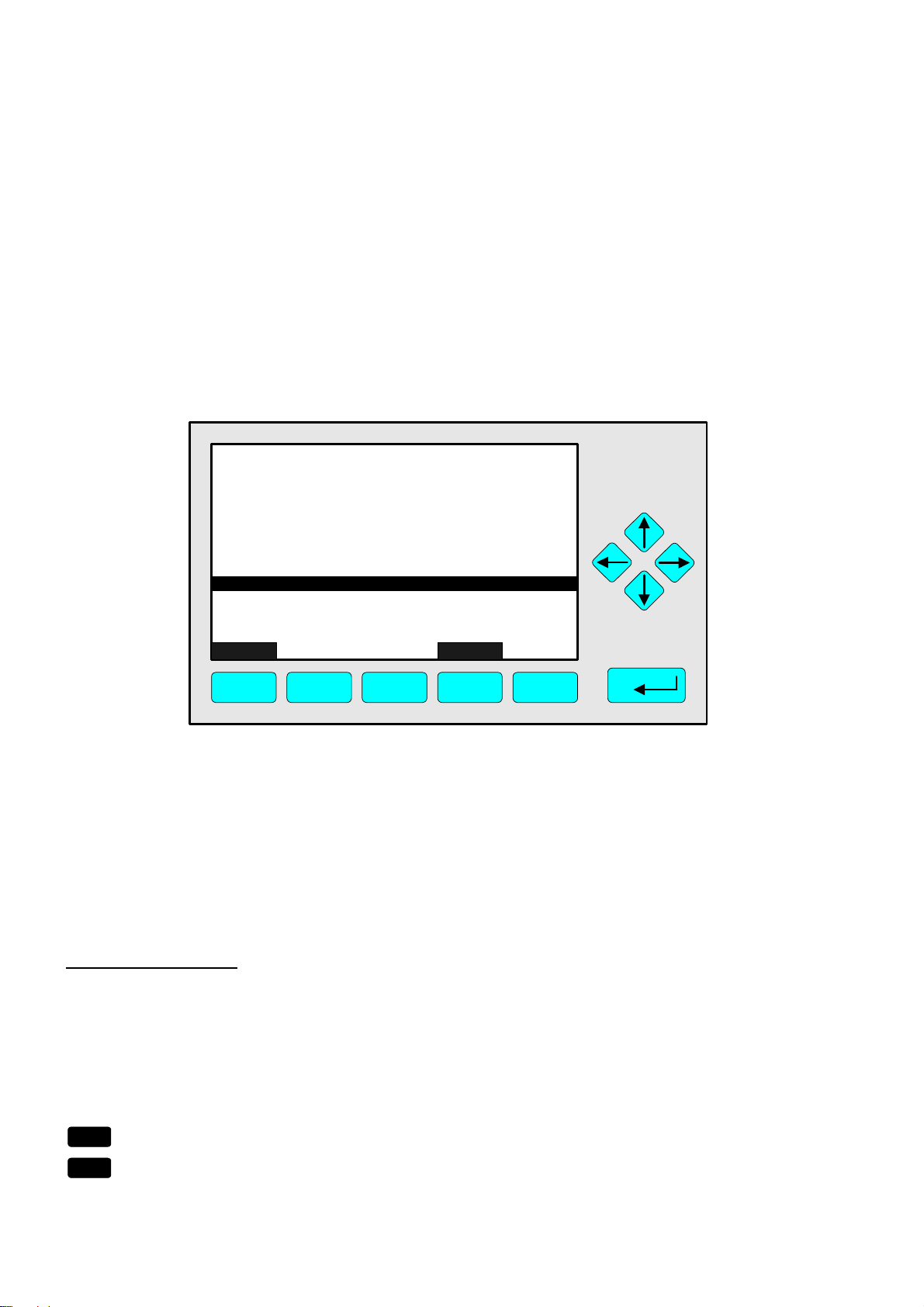
From the menu "Analyzer Module Setup and Controls" you can change to all menus and
submenus of the expert configuration level via the corresponding menu lines.
Changing to the menus and submenus:
♦ Select the menu line you want with the ↓↓ -key or the ↑↑ -key.
If necessary: Change to a further menu page with the F5 key (More...)
♦ Change to the corresponding menu/submenu with the 88 -key or the →→ -key.
Menu "Load Factory Configuration":
If you press the F2 key (ManData) in the menu "Analyzer Module Setup and Controls (1/3)",
you will change to the following menu:
TAG
-- Load Factory Configuration --
- BE CAREFUL with this function -
Replace current configuration with factory settings !
Measure Back...
F1 F2 F3 F4 F5
95.00 ppm
With the function of this menu you can delete the RAM data and load the factory settings
from the Flash-EPROM.
Caution:
This function is irreversible after starting (and confirmation) ! Your RAM settings
will be deleted !
Note:
The same function is available in the menu "Load/Save Analyzer Module Configuration" !
(see section 5.1.17 p. 5-64)
Starting the function:
♦ Press the 88 -key or the →→ -key or
cancel and go back to the last menu page with the F4 key (Back...) or the ←← -key.
♦ If asked: Confirm with the F2 key (Yes) or
cancel and go back to the last menu page with the F4 key (Back...) or the ←← -key.
Further Ramifications via softkeys:
F1
F3
5 - 4
Change to the single component display of the current channel !
Change to the other available channels
of an MLT analyzer or analyzer module !
NGA 2000
90003482(2) [NGA-e (MLT-Software 3.2.X)] 07/98
Chapter 4 !
+
See channel tag !
+
Page 91
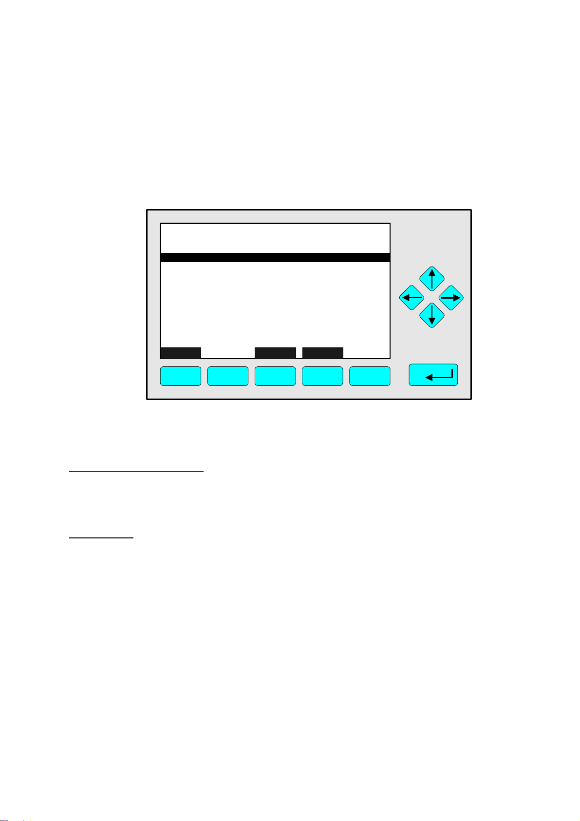
5.1 Analyzer Module Setup
5.1.1 Calibration Parameters
Main Menu — Analyzer and I/O-module expert configuration
↓↓
Analyzer module setup
↓↓
Calibration parameters
↓↓
TAG
-- Calibration Parameters --
Span gases...
Tolerances...
Calibration procedure setup...
Time controlled calibration...
Calibration...
Advanced calibration methods...
Zero gases...
Measure Channel Back...
F1 F2 F3 F4 F5
37.50 ppm
From the menu "Calibration Parameters" you can change to several submenus to set up
the zero and span gas calibration parameters and to start the different calibration methods.
Change to the submenus:
♦ Select the menu line you want with the ↓↓ -key or the ↑↑ -key.
♦ Change to the corresponding submenu with the 88 -key or the →→ -key.
Alternatives:
♦ F1: Change to the single component display !
♦ F3: Change to the other available channels of an MLT analyzer or
analyzer module !
♦ F4: Go back to the last menu page !
90003482(2) [NGA-e (MLT-Software 3.2.X)] 07/98
NGA 2000
5 - 5
Page 92

5.1 Analyzer Module Setup
5.1.1 Calibration Parameters – Span gases
Main Menu — Analyzer and I/O-module expert configuration
Analyzer module setup
Calibration parameters
Span gases
↓↓
↓↓
↓↓
↓↓
MLT25/CH2/R2
-- Span Gas Definition --
Actual span gas concentration: 250.0 ppm
Spangas range -1: 50.00 ppm
Spangas range -2: 250.0 ppm
Spangas range -3: 2500 ppm
Spangas range -4: 10000 ppm
Span gas unit: ppm
"ppm" --> "mg/Nm3" conversion factor: 1.000
Concentration in span gas units: 95.00 ppm
Measure Back...
F1 F2 F3 F4 F5
95.00 ppm
In the menu "Span Gas Definition" you can set up the default value for each range of the
current channel, the actual span gas concentration and the desired span gas unit. The
concentration of each range should be a value between 70 and 110% of the end of range
value.
Set up parameters:
♦ Select any line of variables with the ↓↓ -key or the ↑↑ -key.
♦ Select the variable with the 88 -key or the →→ -key.
♦ Select any digit with the ←← -key or the →→ -key and adjust a new value with
the ↑↑ -key or the ↓↓ -key
resp. select the whole parameter with the ↑↑ -key or the ↓↓ -key.
♦ Confirm the new value with the 88 -key or
cancel and go back to the last value with the F2 key.
The last two lines of variables:
These lines are only information lines. The variables cannot be changed.
Note:
The "ppm → "mg/Nm3" conversion factor can be set up in the menu "General
Concentration Measurement Setup" (see section 5.1.10 p. 5-54) !
5 - 6
NGA 2000
90003482(2) [NGA-e (MLT-Software 3.2.X)] 07/98
Page 93

5.1 Analyzer Module Setup
5.1.1 Calibration Parameters – Tolerances
Main Menu — Analyzer and I/O-module expert configuration
↓↓
Analyzer module setup
↓↓
Calibration parameters
↓↓
Tolerances
↓↓
TAG
-- Tolerances --
Max. zero calibration deviation: 20.00 %
Max. span calibration deviation: 20.00 %
Check deviation: Disabled
Stability tolerance - range 1: 100.00 %
Stability tolerance - range 2: 100.00 %
Stability tolerance - range 3: 100.00 %
Stability tolerance - range 4: 100.00 %
Last zero calibration: Success
Last span calibration: Success
Measure Channel Back...
F1 F2 F3 F4 F5
95.00 ppm
In the menu "Tolerances" you can set up the parameters of the stability controlled
calibration procedure (see p. 5-9/10) in one channel. Besides, you can disable the stability
control and the maximum calibration deviation (deviation control → deviation tolerance).
If you want to set up the parameters of the other channels of an MLT analyzer or analyzer
module, press the F3 key.
Set up parameters:
♦ Select any line of variables with the ↓↓ -key or the ↑↑ -key.
♦ Select the variable with the 88 -key or the →→ -key.
♦ Select any digit with the ←← -key or the →→ -key and adjust a new value with
the ↑↑ -key or the ↓↓ -key
resp. select the whole parameter with the ↑↑ -key or the ↓↓ -key.
♦ Confirm the new value with the 88 -key or
cancel and go back to the last value with the F2 key.
Lines "Last zero calibration/Last span calibration":
The calibration status of the last calibration will be displayed in these two lines.
90003482(2) [NGA-e (MLT-Software 3.2.X)] 07/98
NGA 2000
5 - 7
Page 94

Lines of variables "Max. zero calibration deviation" / "Max. span calibration deviation":
The deviation between two zero or span gas concentrations will be determined during the
stability time of the calibration procedure (see menu "Calibration Procedure Setup"
p. 5-9/10). The maximum calibration deviation is the deviation tolerance expressed as
percentage of the current end of range value. The calibration procedure will only be
possible within this range.
If you choose a very small deviation tolerance, perhaps the calculated deviation is out of
range during the whole calibration procedure and the calibration will run into time out. If
you choose a very large deviation tolerance, the calibration will also be done in ranges
with a little stability.
Value is usually: 10% or 20%
Line of variables "Check deviation":
♦ Enabled: The stability and tolerance control during the calibration procedure will be
based on the values of the menu "Tolerances".
♦ Disabled: The calibration procedure is running without stability and tolerance control.
Any Calibration will be accepted.
Example:
♦ End of range: 1000 ppm
♦ Max. calibration deviation: 20% (equivalent 200 ppm)
♦ Desired value: 990 ppm
♦ Display: 720 ppm
♦ Deviation: 250 ppm (more than 200 ppm!)
♦ Result: Max. calibration procedure time over limit;
Calibration will be canceled !
Potential solutions:
♦ Adjust 100% in the line "Max. zero calibration deviation"
resp. "Max. span calibration deviation"
or
select "Disabled" in the line "Check deviation".
♦ Result: Any Calibration will be accepted!
5 - 8
NGA 2000
90003482(2) [NGA-e (MLT-Software 3.2.X)] 07/98
Page 95

5.1 Analyzer Module Setup
5.1.1 Calibration Parameters – Calibration procedure setup
Main Menu — Analyzer and I/O-module expert configuration
↓↓
Analyzer module setup
↓↓
Calibration parameters
↓↓
Calibration procedure setup
↓↓
TAG
-- Calibration Procedure Setup --
Purge time: 10 s
Procedure times-out after: 120 s
Analog output during calibration: Tracking
Span ranges: Together
Valve position: Samplegas
Stability time: 30 s
Averaging time: 5 s
Measure Channel Back...
F1 F2 F3 F4 F5
95.00 ppm
In the menu "Calibration Procedure Setup" you can set up the parameters for the calibration procedure of the zeroing and spanning in one channel. If you want to set up the
parameters of the other channels of an MLT analyzer or analyzer module, press the F3 key.
Set up parameters:
♦ Select any line of variables with the ↓↓ -key or the ↑↑ -key.
♦ Select the variable with the 88 -key or the →→ -key.
♦ Select any digit with the ←← -key or the →→ -key and adjust a new value with
the ↑↑ -key or the ↓↓ -key
resp. select the whole parameter with the ↑↑ -key or the ↓↓ -key.
♦ Confirm the new value with the 88 -key or
cancel and go back to the last value with the F2 key.
Lines of variables "Purge time" / "Procedure times-out after" and
"Stability time" / "Averaging time" – Informations about the calibration procedures setup:
The measurement signal should be stable in a certain range before zeroing and spanning.
Therefore the analyzer cell should be purged enough with zero gas or span gas before
calibration. Then, after the purge time, the stability time is running. During the stability time
the average over two signals will be calculated. The averaging time determines the time
difference between these two signals.
90003482(2) [NGA-e (MLT-Software 3.2.X)] 07/98
NGA 2000
5 - 9
Page 96

If the deviation of the two values is less then the allowed maximum calibration deviation
(see menu "Tolerances", p. 5-7/8), the calibration may start. If not, the stability control is
starting again until a stable measurement is possible. The time in the line "Procedure
times-out after" is the limit for the whole procedure.
The following figure shows the procedure of the stability controlled zero and span gas
calibration:
Start Span
Calibration
Concentration
Start Zero
Calibration
Averaging
over T
T
i
i
Purge
Time
Stability
Time
Stability
Time
Stability
Time
Stability
Time
Time
Note:
The stability time and the averaging time are factory settings and cannot be changed by
the customer. If you want to use other values, ask your service !
Line of variables "Analog output during calibration":
Here, you can determine if you want to hold the analog output and the limits of a local SIO
in the MLT analyzer module during calibration. The set-ups for a platform or MLT analyzer
SIO have to be done in the menu "Analog Outputs" (see 5.2.1 p. 5-87).
♦ Tracking: The analog output signal is following to the signal during the whole calibra-
tion procedure.
♦ Holding: During the whole calibration procedure the analog output signal is fixed to the
last signal before calibration. This adjustment may be used for instance to control limits
with the analog output.
Sample Gas Zeroing Spanning Sample Gas
5 - 10
Analog Output
Tracking
Analog Output
Holding
0V
NGA 2000
xV
90003482(2) [NGA-e (MLT-Software 3.2.X)] 07/98
Page 97

5.1 Analyzer Module Setup
5.1.1 Calibration Parameters – Calibration procedure setup
Line of variables "Span ranges":
♦ Together:
All measurement ranges of the same channel will be calibrated together.
This is the usual calibration mode.
♦ Separately:
Each measurement range will be calibrated separately.
Line of variables "Valve position":
Options:
♦ Samplegas
♦ Zerogas
♦ Purgegas
♦ Testgas
♦ Spangas-1...-4
♦ Linearizer
♦ Spangas
♦ AllClosed
♦ Other-Proc.
♦ Basic-Status
90003482(2) [NGA-e (MLT-Software 3.2.X)] 07/98
NGA 2000
5 - 11
Page 98

5.1 Analyzer Module Setup
5.1.1 Calibration Parameters – Time controlled calibration
Main Menu — Analyzer and I/O-module expert configuration
↓↓
Analyzer module setup
↓↓
Calibration parameters
↓↓
Time controlled calibration
↓↓
TAG
-- Time Control --
Zero calibration - Day of week: Never
- Hour: 0
- Minute: 0
Span calibration - Day of week: Never
- Hour: 0
- Minute: 0
Zero+Span calibration - Day of week: Never
- Hour: 0
- Minute: 0
Measure Channel Back...
F1 F2 F3 F4 F5
37.50 ppm
ShowList...
In the menu "Time Control" you can determine the starting time of the zero gas calibration
resp. the span gas calibration for one channel. If you want to determine the values of the
other channels of an MLT analyzer or analyzer module, press the F3 key.
Notes:
♦ The time controlled calibration is only possible if the span gas comes from a valve gear!
If the valve gear is not available you have to select "Never" in all lines containing "Day
of week".
♦ A zero gas calibration should be done before starting a span gas calibration. Therefore
the starting time of the zero gas calibration should be different from the starting time of
the span gas calibration. If you select the option "Zero+Span calibration" the zeroing will
run before the spanning, automatically.
Set up time parameters:
♦ Select any line of variables with the ↓↓ -key or the ↑↑ -key.
♦ Select the variable with the 88 -key or the →→ -key.
♦ Select any digit with the ←← -key or the →→ -key and adjust a new value with
the ↑↑ -key or the ↓↓ -key resp. select the whole parameter with the ↑↑ -key or the ↓↓ -key.
Options for day of week: Monday, ..., Sunday, Each day, Never
for hour: 0, 1, 2, 3, ..., 23
for minute: 0, 1, 2, 3, ..., 59
♦ Confirm the new value with the 88 -key or cancel and go back to the last value with F2.
5 - 12
NGA 2000
90003482(2) [NGA-e (MLT-Software 3.2.X)] 07/98
Page 99

Further Parameters:
Via the F5 key (ShowList) you can change to the following submenu:
TAG
-- Auto-Start Procedures --
Position in auto-start list: 1
Erase current position from list !
Erase all positions from list !
Channel tag: Procedure type: Interval mode: Never
Start time: Start date: -
Measure Back...
F1 F2 F3 F4 F5
37.50 ppm
In this submenu you can determine some further parameters of the time controlled
calibration.
Lines "Position in auto-start list", "Erase current position from list !" and
"Erase all positions from list !":
If you have disabled a time controlled calibration in the menu "Time Control" you have to
reset the memory to avoid further calibrations by time control. Starting the function "Erase
current position from list !" will reset the memory for the position selected in the line
"Position in auto-start list".
There are three positions belonging to the following lines in the menu "Time Control":
Position 1: Zero calibration
Position 2: Span calibration
Position 3: Zero+Span calibration
Starting the function "Erase all positions from list !" will delete the set-ups for all kinds of
time controlled calibration in the menu "Time Control".
The last five lines of variables:
These lines will display the parameters of the position selected in the line "Position in
auto-start list".
90003482(2) [NGA-e (MLT-Software 3.2.X)] 07/98
NGA 2000
5 - 13
Page 100

5 - 14
NGA 2000
90003482(2) [NGA-e (MLT-Software 3.2.X)] 07/98
 Loading...