

Page 1
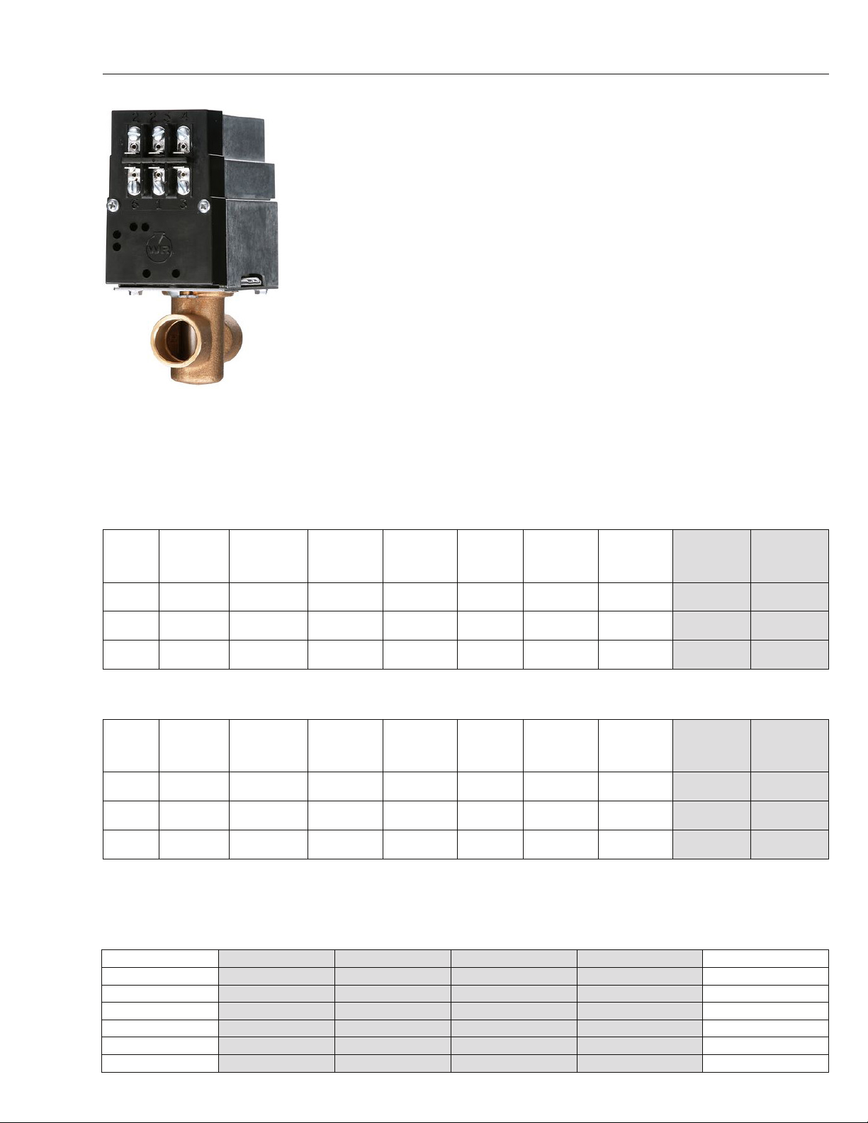
HYDRONIC ZONE VALVES 1300 SERIES
1300 SERIES
HYDRONIC ZONE VALVES
1300 Series valves for zoning systems up to 50 PSI operate quietly and efficiently
providing years of reliable service.
FEATURES
• Self-aligning barrel-type valve stem design
• Made of a corrosion-resistant stainless steel
• Motor can be removed from valve assembly without draining system
• Built-in auxiliary contacts to control burner or circulator relay
• Automatic recycling manual operator shows valve position at all times
• Screw terminal wiring panel for added convenience
SPECIFICATIONS
1311-102
Electrical Ratings ....................................................................................................... 24 VAC
........................................................................................................................... 1311 - 0.4A
........................................................................................................................... 1361 - 0.2A
.................................................................................................................. Aux Switch - 2.0A
3-WIRE, 24V VALVES WITH SCREW TERMINAL WIRING PANEL AND AUXILIARY SWITCH
(See table at bottom for compatible thermostats)
24 VAC
TUBING
SIZE (I.D.)
3/4"
1"
1-1/4"
THERMOSTAT
CIRCUIT
RATING TIME CYCLE
0.4A ①
0.4A ①
0.4A ①
Open: 45 seconds
Close: 45 seconds
Open: 45 seconds
Close: 45 seconds
Open: 45 seconds
Close: 45 seconds
MAXIMUM
DIFFERENTIAL
ACR OS S VALVE
15 PSI 24 0° F (116°C) 50 PSI
15 PSI 24 0° F (116°C) 50 PSI
15 PSI 24 0° F (116°C) 50 PSI
MAXIMUM
WATER TEMP.
MAXIMUM
SYSTEM
PRESSURE
FLOW
CAPACIT Y CV
23.5 ③
37. 0 ③
42.2 ③
FRICTION LOSS
EQUIVALENTS
FT. OF TUBING
2.5 1311-102 13 11 102S1
3.5 1311-103 13 11 103S1
6.5 1311-104 13 11 104S1
2-WIRE, 24V VALVES WITH SCREW TERMINAL WIRING PANEL AND AUXILIARY SWITCH
24 VAC
1"
THERMOSTAT
CIRCUIT
RATING TIME CYCLE
0.2A ②
0.2A ②
0.2A ②
Open: 45 seconds
Close: 60 seconds
Open: 45 seconds
Close: 60 seconds
Open: 45 seconds
Close: 60 seconds
TUBING
SIZE (I.D.)
3/4"
1-1/4"
Valve current is 0.4A only during opening or closing. For proper anticipation, select thermostat designed for use with a 3-wire zone valve.
①
Valve current is 0.52A when opening but 0.2A when fully open: therefore set anticipator for 0.2A.
②
GPM @ 1 PSI drop.
③
MAXIMUM
DIFFERENTIAL
ACR OS S VALVE
15 PSI 24 0° F (116°C) 50 PSI
15 PSI 24 0° F (116°C) 50 PSI
15 PSI 24 0° F (116°C) 50 PSI
MAXIMUM
WATER TEMP.
MAXIMUM
SYSTEM
PRESSURE
FLOW
CAPACIT Y CV
23.5 ③
37. 0 ③
42.2 ③
FRICTION LOSS
EQUIVALENTS
FT. OF TUBING
2.5 1361-102 13 61 102S1
3.5 1361-103 13 61 103S1
6.5 1361-104 13 61 104S1
MODEL
NUMBER
MODEL
NUMBER
ITEM
NUMBER
ITEM
NUMBER
1311 COMPATIBLE THERMOSTATS TABLE
MECHANICAL/ DIGITAL MODEL NUMBER ITEM NUMBER UPGRADE MODEL NUMBER UPGRADE ITEM NUMBER MECHANICAL/ DIGITAL
Mechanical 1E56N-444 1E56N-444 1F95 -0 671 1F95 -0 671 Premium Digital
Mechanical 1F56N-444 1F56N-444 1F95- 068 0 1F95-0680 Premium Digital
Digital 1F85U-22NP 1F85U -22NP 1F95-1280 1F95 -1280 Premium Digital
Digital 1F85U-22PR 1F85U-22PR 1F95-1291 1F95-1291 Premium Digital
Digital 1F85U-42NP 1F85U-42NP 1F95EZ-0671 1F95EZ-0671 Premium Digital
Digital 1F85U-42PR 1F85U-42PR 1F97-1277 01F97 1277 Premium Digital
R-4899_053_12.11.20
Page 2
1300 SERIES HYDRONIC ZONE VALVES
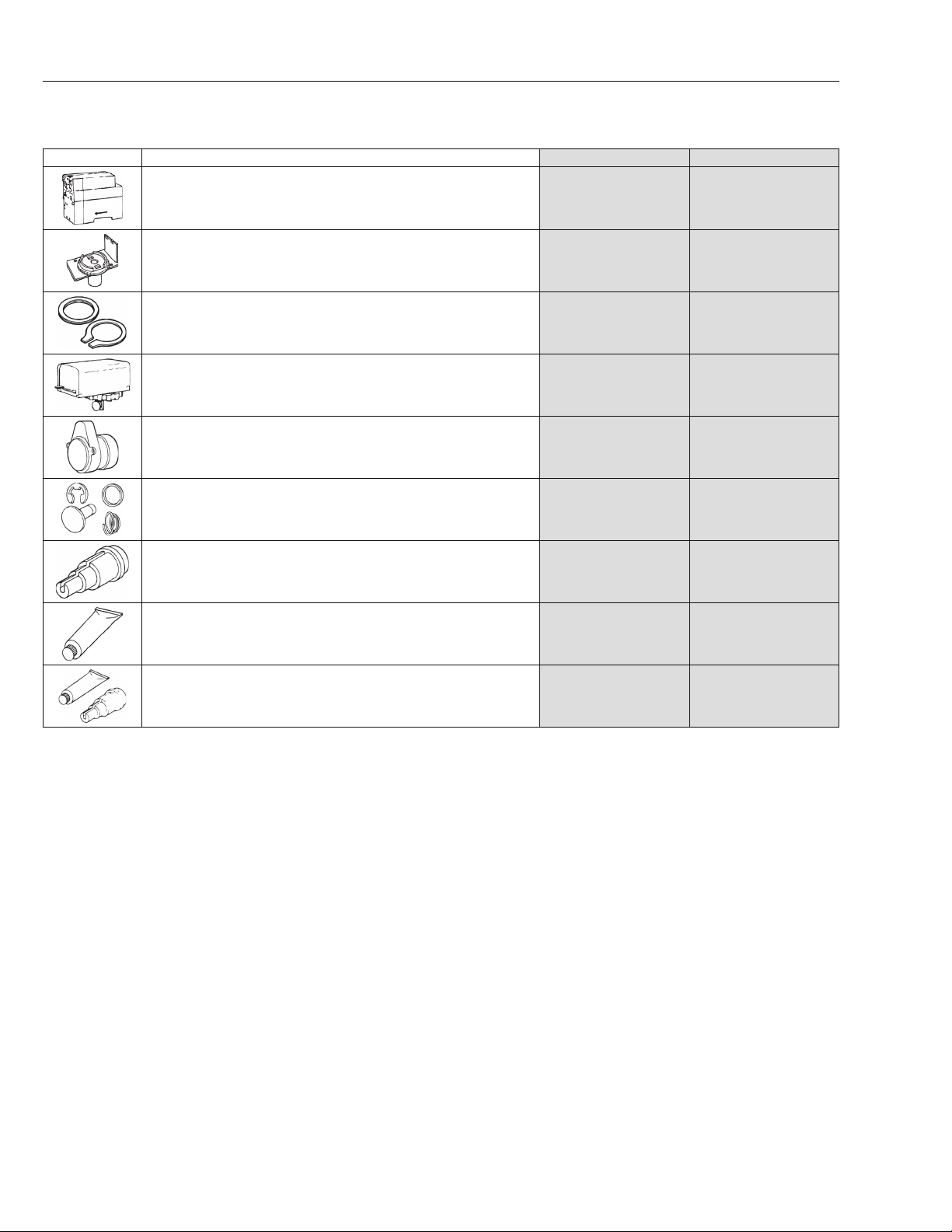
PARTS AND ACCESSORIES
IMAGE DESCRIPTION MODEL NUMBER ITEM NUMBER
1300 Hydronic Zone Valve Motor assemblies
For 1311-102, -103, -104
For 1361-102, -103, -104
Water seal replacement kit not included
1300 Hydronic zone valve assemblies
1311-102 and 1361-102 (3/4")
1311-103 and 1361-103 (1")
1311-104 and 1361-104 (1-1/4")
1300 Hydronic zone water seal Replacement (Quad ring. "O" ring, Tru-arc ring and cotter pin)
1311-102 and 1361-102 (3/4")
1311-103 and 1361-103 (1")
1311-104 and 1361-104 (1-1/4")
F19- 0097
F19-0104
F84-0433
F84-0434
F84-0435
F92-0227
F92-0228
F92-0229
F0019 009700S1
F0019 010400S1
F0084 043300S1
F0084 043400S1
F0084 043500S1
F0092 022700S1
F0092 022800S1
F0092 022900S1
13A00 Hydronic zone power head (includes seal ring) For 2-way zone Valves
25 VAC with conduit hub
25 VAC with plug-in panel that includes an auxiliary switch
13A00 Hydronic zone motor
24 VAC motor
13A00 Hydronic zone valve disc
Contains one disc, spring, E-ring and body seal ring
Hydronic well adapter for 1100 series bulbs F71-0924 F0071 092400S1
Hydronic well heat transfer compound F145-0163 F0145 016300S1
Hydronic well adapter and heat transfer compound F71-0924 and F145-0163 packed together F145-0650 F0145 065000S1
F19-0181
F19-0187
F19-0190 F0019 019000S1
F84-1215 F0084 121500S1
F0019 018100S1
F0019 018700S1
R-4899_053_12.11.20
Page 3

HYDRONIC ZONE VALVES 1300 SERIES WIRING INFORMATION
1311 THREE-WIRE ZONE VALVE
TERMINALS 1, 2 = POWER TO VALVE
1 = 24 VAC NEUTRAL
2 = 24 VAC HOT
TERMINALS 5,4,6 = SPDT THERMOSTAT
5 = POWER (SAME AS 2 INTERNALLY)
4 = OPENS VALVE
6 = CLOSES VALVE
TERMINALS 2, 3 = AUXILIARY SWITCH
2, 3 BECOME SAME POINT ON CALL FOR HEAT
TERMINALS 1, 3 = POWER OUT TO AUXILIARY CIRCUIT
ON CALL FOR HEAT
TROUBLESHOOTING:
1. Attach a voltmeter to terminals 1 and 2. Power (24 volts) should always be present on 1 and 2. If power is interrupted check
transformer or power source.
2. With a voltmeter attached as above, jumper terminals 5 and 4 to verify the valve opens. If power is present on 1 and 2 but
the valve fails to open check connections. Replace motor assembly (replacement Motor # F19-0097) if condition persists. When the
valve opens, break the connection between 5 and 4 and jumper between 5 and 6. The valve should close. If the valve fails to close
replace motor assembly.
3. Terminals 2 and 3 (auxiliary circuit) become the same point electrically when the valve opens. Because terminal 2 is 24 volts hot, a
voltmeter should read 24 volts between terminal 3 and terminal 1 (neutral) when the valve is open.
NOTE: If the auxiliary circuit terminals (2 and 3) are being attached to a control circuit with a separate transformer the transformers
must be in phase or one transformer may be damaged. If phasing the transformers is not possible a 24 volt isolation relay can be
installed with the coil attached to terminals 1 and 3 and the contacts can be used to operate the control circuit. The relay will energize
when the valve opens.
For complete installation instructions visit our website.
R-4899_053_12.11.20
Page 4

1300 SERIES WIRING INFORMATION HYDRONIC ZONE VALVES
1361 TWO-WIRE ZONE VALVE
TERMINALS 1, 2 = POWER TO VALVE
1 = 24 VAC NEUTRAL
2 = 24 VAC HOT
TERMINALS 2, 4 = SPST THERMOSTAT
MAKE TO OPEN, BREAK TO CLOSE
TERMINALS 2, 3 = AUXILIARY SWITCH
2, 3 BECOME SAME POINT ON CALL FOR HEAT
TERMINALS 1, 3 = POWER OUT TO AUXILIARY CIRCUIT
ON CALL FOR HEAT
TROUBLESHOOTING:
1. Attach a voltmeter to terminals 1 and 2. Power (24 volts) should always be present on 1 and 2. If power is interrupted check
transformer or power source.
2. With voltmeter attached as above, jumper terminals 2 and 4 to verify the valve opens. If power is present on 1 and 2 but the valve
fails to open check connections. Replace motor assembly (Replacement Motor # F19-0104) if condition persists. When the jumper is
removed between 2 and 4 the valve should close. If the valve fails to close replace motor assembly.
3. Terminals 2 and 3 (auxiliary circuit) become the same point electrically when the valve opens. Because terminal 2 is 24 volts hot, a
voltmeter should read 24 volts between terminal 3 and terminal 1 (neutral) when the valve is open.
NOTE: If the auxiliary circuit terminals (2 and 3) are being attached to a control circuit with a separate transformer the transformers
must be in phase or one transformer may be damaged. If phasing the transformers is not possible a 24 volt isolation relay can be
installed with the coil attached to terminals 1 and 3 and the contacts can be used to operate the control circuit. The relay will energize
when the valve opens.
For complete installation instructions visit our website.
R-4899_053_12.11.20
 Loading...