

Installation Sheet
June 2006
Introduction
Type HSR
This manual provides instructions for the installation,
startup, and adjustment of the Type HSR pressure
regulator. If maintenance is required, refer to the Type
HSR Instruction Manual, form 5753. To receive a copy of
the instruction manual, contact your Fisher Sales Ofce or
Sales Representative.
Specications
Maximum Emergency Inlet Pressures
150 psi (10,3 bar)
Maximum Emergency Outlet (Casing) Pressures
25 psig (1,72 bar)
Outlet Pressure Ranges
4 to 6-inches w.c. (10 to 15 mbar),
6 to 8-inches w.c. (15 to 20 mbar),
8 to 10-inches w.c. (20 to 25 mbar),
10 to 12.5-inches w.c. (25 to 31 mbar),
12.5 to 20-inches w.c. (31 to 50 mbar),
20 to 35-inches w.c. (50 to 87 mbar),
1.25 to 2.2 psig (0,09 to 0,15 bar)
Temperature Capabilities
-20° to 160°F (-29° to 71°C)
(2)
(1)
(1)
Installation
WARNING
!
Personal injury, equipment damage, or
leakage due to escaping gas or bursting
of pressure-containing parts might result
if these regulators are overpressured or
installed where service conditions could
exceed the limits for which the regulators
were designed, or where conditions exceed
any ratings of the adjacent piping or
piping connections. To avoid such injury
or damage, provide pressure-relieving
or pressure-limiting devices (as required
by the appropriate code, regulation or
standard) to prevent service conditions
from exceeding those limits.
Additionally, physical damage to a
regulator could cause personal injury and
property damage due to escaping gas. To
avoid such injury and damage, install the
regulator in a safe location.
A regulator may vent some gas to the
atmosphere in hazardous or ammable gas
service, vented gas might accumulate and
cause personal injury, death or property
damage due to re or explosion. Vent
a regulator in hazardous gas service to
a remote, safe location away from air
intakes or any hazardous location. The
vent line must be protected against
condensation or clogging.
Before installing the regulator, check for damage which
might have occurred in shipment. Also check for dirt
or foreign matter which may have accumulated in the
regulator body or in the pipeline. Apply pipe compound to
the male threads of the pipeline and install the regulator
so that the ow is in the direction of the arrow cast on
the side of the body. The diaphragm actuator assembly
can be rotated to any position relative to the body, in 90°
increments. Remove the two cap screws that hold the
body to the actuator in order to rotate the diaphragm
actuator assembly.
Do not install the regulator in a location where there can
be excessive water accumulation, such as directly beneath
a downspout or in an undrained pit.
To obtain the maximum ow capacities or other
performance characteristics, the length of pipe from the
regulator outlet to the meter should have no bends and
should be the same size as the regulator outlet. Replace
the regulator if water gets into the spring case or the lower
casing of the regulator.
CAUTION
You are advised to use new vent piping
because defective threads on the relief
vent piping may interfere with the venting
assembly if the piping obstructs the
movement of the vent apper.
On indoor installations, the vent should be piped outside
the building. Remove the screen from the regulator vent
connection and connect vent piping from that connection
to the outdoors. Install a weather and insect resistant
vent assembly on the outside end of the pipe. Inspect
the vent opening regularly. On some installations, it may
be necessary to install the regulator beneath a protective
hood. The vent should be pointing or sloping down
sufciently to allow any condensate to drain. Also check
the regulator periodically for external or internal corrosion.
Overpressure Protection
WARNING
!
Some type of overpressure protection is
needed if actual inlet pressure can exceed
the outlet pressure rating. Overpressuring
any portion of this equipment may cause
damage to regulator parts, leaks in
the regulator, or personal injury due to
bursting of pressure-containing parts or
explosion of accumulated gas.
www.emersonprocess.com/regulators
D103075X012
Type HSR
Type HSR regulators provide internal relief that limits the
total outlet pressure buildup over setpoint. This internal relief
may be adequate for the application, if not, provide additional
pressure relief or a pressure-limiting device downstream.
Regulators should be inspected for damage after any
overpressure condition.
WARNING
!
To avoid personal injury or property damage
due to explosion or damage to regulator or
downstream components during startup,
release downstream pressure to prevent an
overpressure condition on the diaphragm of
the regulator.
In order to avoid an overpressure condition
and possible equipment damage, pressure
gauges should always be used to monitor
pressures during startup.
Startup
With proper installation completed, slowly open the
shutoff valve. Check all connections for leaks. Check the
downstream equipment for proper operations.
Adjustment
To increase the outlet pressure setting, turn the adjusting
screw clockwise. To reduce the outlet pressure setting, turn
the adjusting screw counterclockwise. A pressure gauge
should always be used to monitor downstream pressure
while adjustments are being made. Do not adjust the spring
to produce an outlet pressure setting above the limit identied
on the information label. If the required pressure setting is
not within the range of the spring being used, substitute with
the correct spring. When changing the spring, also change
the range identied on the information label to indicate the
actual pressure range of the spring in use. After the spring
adjustment has been completed, replace the closing cap.
27
9
17
T80573-2A
15
23
5
22
10
16
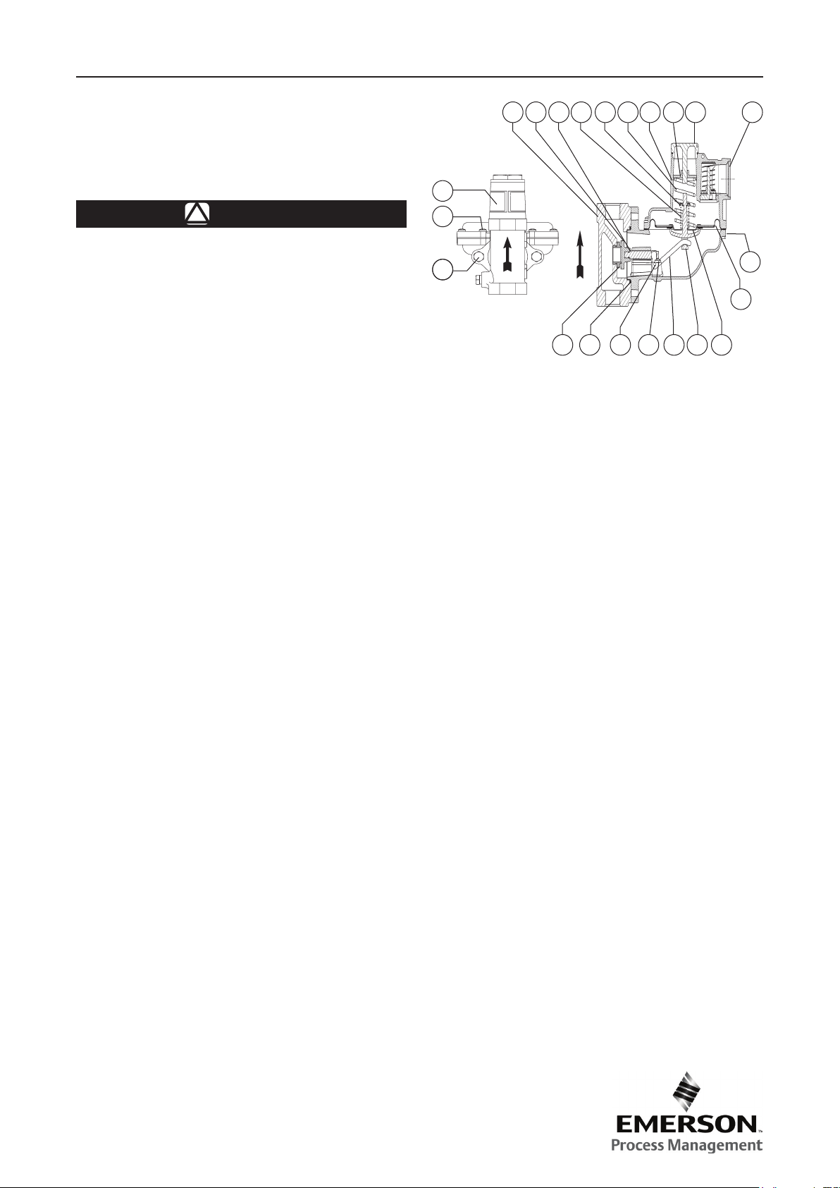
Type HSR Regulator Assembly
Parts List
Key Description
1 Spring Case Assembly
2 Lower Casing
3 Screen
4 Lever
5 Stem
6 Straight Pin
7 Machine Screw (2 required)
8 Closing Cap
9 Machine Screw (8 required)
10 Relief Valve Spring
11 Diaphragm
12 Pusher Post
13 Lower Spring Seat
14 Relief Spring Retainer
15 Body
16 O-Ring
17 Cap Screw (2 required)
22 Orice
23 Disc
25 Spring
26 Adjusting Screw
27 Information Label
14
8
26
1
25
6
4
7
12
3
2
11
13
Industrial
USA - Headquarters
McKinney, Texas 75070 USA
Tel: 1-800-558-5856
Outside U.S. 1-469-293-4201
Asia-Pacic
Shanghai, China 201206
Tel: 86-21-5899 7887
Europe
Bologna, Italy 40013
Tel: 39 051 4190611
For further information visit www.emersonprocess.com/regulators
The Emerson logo is a trademark and service mark of Emerson Electric Co. All other marks are the property of their prospective owners. Fisher is a mark owned by Fisher Controls, Inc.,
a business of Emerson Process Management.
The contents of this publication are presented for informational purposes only, and while every effort has been made to ensure their accuracy, they are not to be construed as warranties
or guarantees, express or implied, regarding the products or services described herein or their use or applicability. We reserve the right to modify or improve the designs or specications
of such products at any time without notice.
Emerson Process Management does not assume responsibility for the selection, use or maintenance of any product. Responsibility for proper selection, use and maintenance of any
Emerson Process Management product remains solely with the purchaser.
©Fisher Controls International, Inc., 2003, 2006; All Rights Reserved
Natural Gas Technologies
USA - Headquarters
McKinney, Texas 75070
Tel: 1-800-558-5856
Outside U.S. 1-469-293-4201
Asia-Pacic
Singapore, Singapore 128461
Tel: +65 6777 8211
Europe
Bologna, Italy 40013
Tel: 39 051 4190611
Gallardon, France 28320
Tel: +33 (0)2 37 33 47 00
Industrial/High Purity
TESCOM
Elk River, Minnesota 55330 USA
Tel: 1-763-241-3238
Selmsdorf, Germany 23923
Tel: +49 (0) 38823 31 0
 Loading...