

Installation, Operation and Maintenance Manual
VCIOM-15257-EN Rev. 1
May 2020
EIM HQ Series Quarter-Turn Electric Actuator
Models HQ-006 / Manual HQ-402-0606

Notes
May 2020
Installation, Operation and Maintenance Manual
VCIOM-15257-EN Rev. 1
This page intentionally left blank

Installation, Operation and Maintenance Manual
VCIOM-15257-EN Rev. 1
Table of Contents
Section 1: General
Generalities ............................................................................................................. 1
Section 2: Actuator Mounting
Actuator Mounting ................................................................................................. 2
Section 3: External Construction
External Construction ............................................................................................. 3
Section 4: Standard Wiring Diagram
Standard Wiring Diagram ........................................................................................ 4
Table of Contents
May 2020
Section 5: Manual Override
Manual Override ..................................................................................................... 5
Section 6: Electrical Connection
Electrical Connection .............................................................................................. 6
Section 7: Limit Switch Setting Instructions
Limit Switch Setting Instructions ............................................................................. 7
Section 8: Lubrication
Lubrication .............................................................................................................. 8
Section 9: MDPI Settings
MDPI Settings ......................................................................................................... 9
Section 10: Maintenance and Storage
Maintenance and Storage ..................................................................................... 10
Section 11: Troubleshooting
Troubleshooting ................................................................................................... 11
Table of Contents
Section 12: Product Features and Specications
Product Features and Specications ...................................................................... 12
i

Section 1: General
May 2020
Section 1: General
HQ series electric actuators are design to provide reliable and efcient operation of 90°
quarter-turn valves, dampers, etc.
WARNING
!
Use caution when working in, with, or around valves and actuators. High pressures, forces,
voltages and ammable media can be present. Failure to follow instructions for proper
electrical wiring, storage, set-up and maintenance may cause serious injury, damage
equipment, or void warranty.
Installation, Operation and Maintenance Manual
VCIOM-15257-EN Rev. 1
1
General
Installation, Operation and Maintenance Manual
VCIOM-15257-EN Rev. 1
Section 2: Actuator Mounting
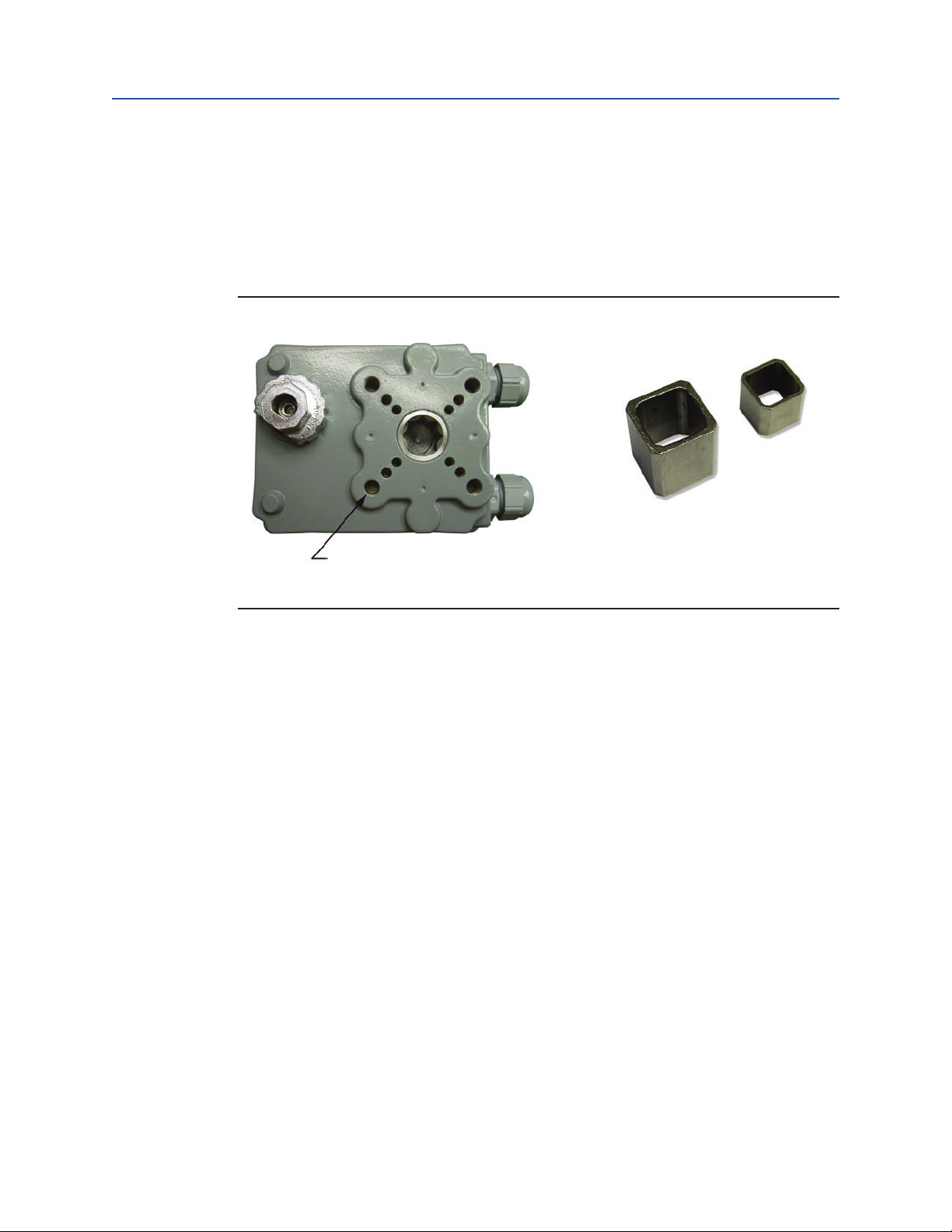
The actuator may be mounted in any position. The HQ-006 actuator is supplied with a
female output drive and adaptor bushings. ISO5211 FO3/FO5 and FO7 Bolt patterns are
provided for actuator mounting.
Figure 1 Actuator Mounting Flange and Adapter Bushings
Section 2: Actuator Mounting
May 2020
9 mm ID
11 mm ID
F03, F05 and F07 Bolt Circles
Actuator Mounting
2

Section 3: External Construction
May 2020
Installation, Operation and Maintenance Manual
Section 3: External Construction
Figure 2
CABLE ENTRY
2 Plcs PG 0.531" (13.5)
(1/4" - 1/2" Wire Cable)
VCIOM-15257-EN Rev. 1
3
External Construction

Installation, Operation and Maintenance Manual
Section 4: Standard Wiring Diagram
VCIOM-15257-EN Rev. 1
Section 4: Standard Wiring Diagram
Figure 3
INCOMING POWER
1 PH (110 OR 220 V A C)
LIVE
May 2020
AUX. CONTACT
2 EXTRA SWITCHES
MAX. 250 V AC 3 A
CLOSE
LAMP
OPEN
LAMP
OPENSTOPCLOSE
HEATER
2W
NEUTRAL
BASE
EARTH
Standard Wiring Diagram
4

Section 5: Manual Override
May 2020
Installation, Operation and Maintenance Manual
Section 5: Manual Override
The HQ-006 actuator comes standard with a manual override nut. This is located on the
bottom of the unit, and can be easily operated with a 5M wrench.
Figure 4
VCIOM-15257-EN Rev. 1
5
Manual Override

Installation, Operation and Maintenance Manual
VCIOM-15257-EN Rev. 1
Section 6: Electrical Connection
• Move valve to mid-position by override nut. This will allow sufcient time to stop
actuator in case of improper hook-up.
• Identify means of removing power during hook-up.
• Be sure no erroneous remote control signals can be received causing actuator
to energize.
• Electrically operate the valve in the open direction. If the valve closes, actuator
must be stopped and checked for improper eld wiring.
• Set all eld conduit entries in accordance with National Electric Code Requirements.
Section 6: Electrica l Connection
May 2020
Electrica l Connection
6
Section 7: Limit Switch Setting Instructions
May 2020
Installation, Operation and Maintenance Manual
VCIOM-15257-EN Rev. 1
Section 7: Limit Switch Setting Instructions
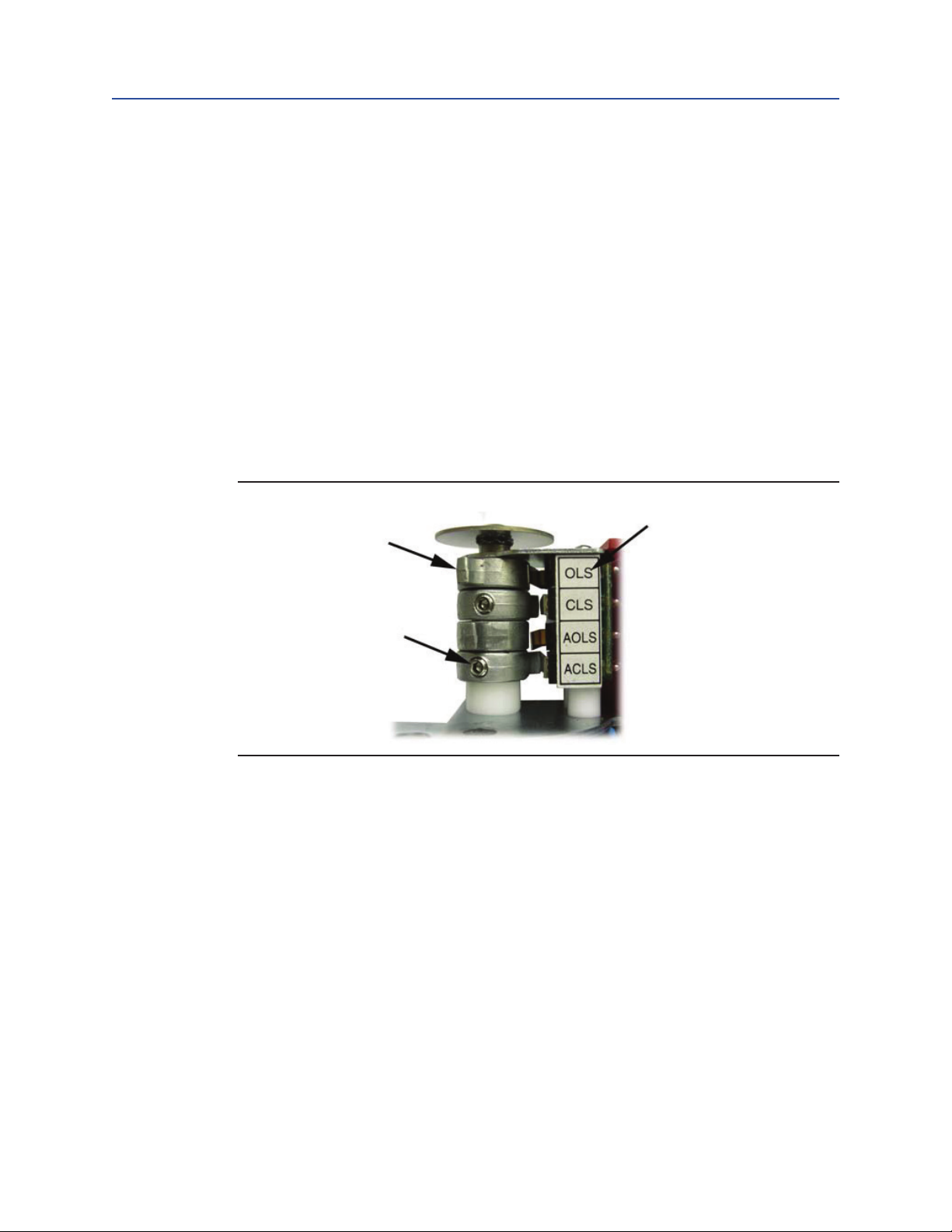
• Operate the actuator manually to closed position
• Using a hex wrench, loosen the cam adjustment screw in the CLS limit switch cam
• Rotate the CLS cam towards limit switch lever until the switch ‘clicks’
• Tighten set screw with hex wrench
• Operated the actuator manually to open position
• Using a hex wrench, loosen the cam adjustment screw in the OLS limit switch cam
• Rotate the OLS can towards limit switch lever until the switch ‘clicks’
• Tighten set screw with hex wrench
• Repeat for AOLS and ACLS
Figure 5
Limit
Cam
Switch
Cam
adjustment
screw
7
Limit Switch Setting Instructions

Installation, Operation and Maintenance Manual
VCIOM-15257-EN Rev. 1
Section 8: Lubrication
The HQ series actuators are totally enclosed units with a permanently lubricated gear
trains (Moly EP Grease). Once installed lubrication should not be required. However,
periodic preventative maintenance will extend the operating life of the actuator.
Section 8: Lubrication
May 2020
Lubrication
8

Section 9: MDPI Settings
May 2020
Section 9: MDPI Settings
• Manually rotate actuator to fully closed position
• Remove actuator cover
• Loosen indicator screw
• Adjust indicator to correct orientation
• Tighten indicator screw
• Replace cover
• Check indicator alignment
Installation, Operation and Maintenance Manual
VCIOM-15257-EN Rev. 1
9
MDPI Settings

Installation, Operation and Maintenance Manual
VCIOM-15257-EN Rev. 1
Section 10: Maintenance and Storage
Section 10: Maintenance and Storage
At least once a year a check should be made of your EIM HQ Series Actuator.
• Disconnect all power to actuator.
• Open electrical enclosure. Inspect and tighten all electrical connections.
• Visually inspect for any electrical or mechanical damage. Replace worn or
damaged components.
• Check lubrication consistency and levels. Fill or replace if required.
Actuators must be stored in a clean, cool and dry area. The unit shall be stored with the
cover installed and the conduit openings sealed. Storage must be off the oor, covered
with a sealed dust protector.
May 2020
Maintenance and Storage
10

Section 11: Troubleshooting
May 2020
Installation, Operation and Maintenance Manual
Section 11: Troubleshooting
The following instructions are offered for the most common difculties encounter during
installation and start-up.
Table 1.
SYMPTOM PROBABLE CAUSE CORRECTIVE ACTION
Open in control circuit
Motor will not run
No power available
to actuator
Manual override
nut hard to turn
Valve only opens
or closes partially
with motor
Manual override
nut will not
operate valve
Motor runs but will
not operate valve
Insulation resistance breakdown
in motor
Tripped circuit breaker Reset circuit breaker
Valve stem improperly lubricated Lubricate with grease
Actuator lubrication has broken down
Valve packing gland too tight
Jammed valve Refer to valve maintenance
Limit switch improperly set Check setting and reset if necessary
Stripped gearing Replace as necessary
Broken handwheel shaft Replace as necessary
Broken valve stem Repair or replace as necessary
Stripped gearing Replace as necessary
VCIOM-15257-EN Rev. 1
Refer to appropriate wiring diagram
and check for continuity
Perform Megger Test
Clean out old grease and replace
with recommended lubricant
Loosen packing gland nuts as
necessary
11
Troubleshooting

Installation, Operation and Maintenance Manual
VCIOM-15257-EN Rev. 1
Section 12: Product Features and Specications
Section 12: Product Features
and Specications
Enclosure Rated Weatherproof IP67
Enclosure High grade aluminium alloy, corrosion coated
Power Supply 110/220 V AC, 1 PH, 50/60 Hz
Motor Reversible Motor
Limit Switches 4 x open/close SPDT, 250VAC 3 A rating
Stall Protection Built-in thermal protection
Indicator MDPI (Mechanical Dial Position Indicator)
Manual Override Manual Override Nut
Space Heater 2 W anti-condensation
May 2020
Conduit Entries (2) x PG13.5
Lubrication Grease moly EP
Ambient Temperatur -20 °C – +70 °C
External Coating Dry powder polyester
Product Features and Specications
12

World Area Conguration Centers (WACC) offer sales support, service, inventory and commissioning to our global customers.
Choose the WACC or sales ofce nearest you:
NORTH & SOUTH AMERICA
19200 Northwest Freeway
Houston TX 77065
USA
T +1 281 477 4100
Av. Hollingsworth
325 Iporanga Sorocaba
SP 18087-105
Brazil
MIDDLE EAST & AFRICA
P. O. Box 17033
Jebel Ali Free Zone
Dubai
T +971 4 811 8100
P. O. Box 10305
Jubail 31961
Saudi Arabia
T +966 3 340 8650
T +55 15 3413 8888
24 Angus Crescent
ASIA PACIFIC
Longmeadow Business Estate East
P.O. Box 6908 Greenstone
No. 9 Gul Road
#01-02 Singapore 629361
T +65 6777 8211
No. 1 Lai Yuan Road
1616 Modderfontein Extension 5
South Africa
T +27 11 451 3700
EUROPE
Wuqing Development Area
Tianjin 301700
P. R. China
T +86 22 8212 3300
Holland Fasor 6
Székesfehérvár 8000
Hungary
T +36 22 53 09 50
Strada Biffi 165
29017 Fiorenzuola d’Arda (PC)
Italy
T +39 0523 944 411
For complete list of sales and manufacturing sites, please visit
www.emerson.com/actuationtechnologieslocations or contact us at
info.actuationtechnologies@emerson.com
www.emerson.com/eim
VCIOM-15257-EN ©2020 Emerson. All rights reserved.
The Emerson logo is a trademark and service mark of Emerson Electric Co.
TM
EIM
is a mark of one of the Emerson family of companies.
All other marks are property of their respective owners.
The contents of this publication are presented for informational purposes
only, and while every effort has been made to ensure their accuracy,
they are not to be construed as warranties or guarantees, express or
implied, regarding the products or services described herein or their use
or applicability. All sales are governed by our terms and conditions, which
are available upon request. We reserve the right to modify or improve the
designs or specifications of such products at any time without notice.
 Loading...