

Page 1

Operating Instructions
HPR12K-00
1. General Install
Connecting the input power cable, output load cable and communication wire according
to the below figure.
Embedded Power for
Business-Critical Continuity
Rev.06.09.10
HPR12K-00
1 of 6
Aux. DC
Output
AC INPUT AC INPUT AC INPUT AC INPUT
I2C/PMBus
Communication
Main DC Output
Main DC Output
AC Line Input
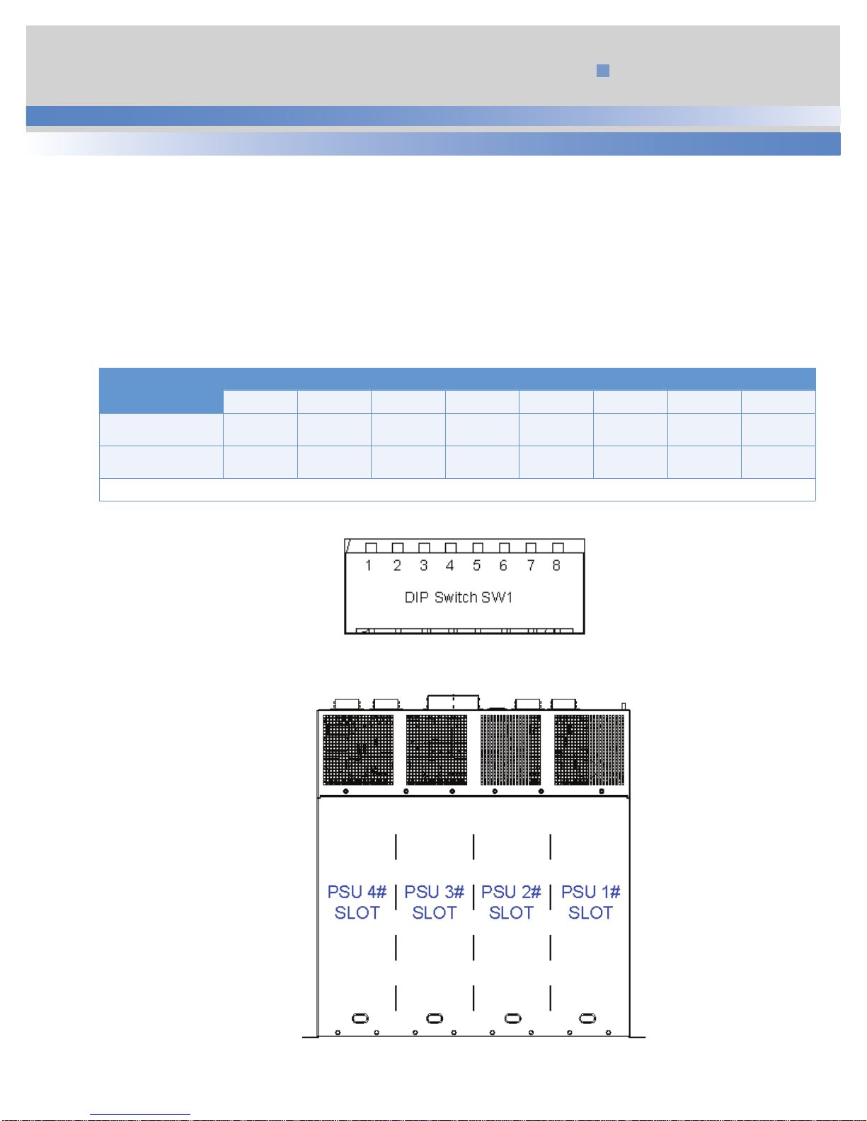
2. General Settings
Unless otherwise specified, when the PSON# switch is de-asserted (48V o/p is disabled).
It is means Manual ON/OFF DIP switch SW1 should be default according to below table.
And It must be checked before shipping.
DIP switch SW1 setting as a default
Power Supplies
Status
OFF Up Down Up Down Up Down Up Down
PSU 1# PSU 2# PSU 3# PSU 4#
CH 1 CH 2 CH 3 CH 4 CH 5 CH 6 CH 7 CH8
Note 1. The status Down means set to ON position. The status UP means set to OFF position.
Note 2. Programming Switch SW1 default settings:
PSON switches : OFF
PSKILL switches : ON
Page 2
Technical Reference Note
3. ON/OFF Operation (PSON#)
3.1 Manual ON/OFF Operation
The DIP switch SW1 used turn on or off the PSU by manually. The PSU in SLOT1 is turn on when the CH1 of DIP switch
SW1 turn on. The other PSU see Table 1.
Note : DIP switch CH2 should be set to ON as a default. Incase if CH2 is set to off, Power supply is slot 1 will not turn on
even if CH1 is set to ON position.
Table 1 PSON# Switch Characteristics
Embedded Power for
Business-Critical Continuity
Rev.06.09.10
HPR12K-00
2 of 6
Power Supplies
Status
ON Down Down Down Down Down Down Down Down
OFF Up Down Up Down Up Down Up Down
Note. The status Down means set to ON position. The status UP means set to OFF position.
PSU 1# PSU 2# PSU 3# PSU 4#
CH 1 CH 2 CH 3 CH 4 CH 5 CH 6 CH 7 CH8
Figure 1: DIP Switch for ON/OFF Operation
Figure 2: The SLOTs define of Rack
Page 3

Embedded Power for
Business-Critical Continuity
3.2 Remote ON/OFF
The per PSON# signal is required to remotely turn on/off the power supply. PSON# is an active low signal that turns on
the +48VDC power rail. When this signal is not pulled low by the system, or left open, the +48VDC output turns off.
The 5Vsb output remains on. This signal is pulled to a standby voltage by a pull-up resistor internal to the power supply. The power supply fan(s) shall operate at the lowest speed.
Table 2 PSON# Signal Characteristics
Signal Type
PSON# = Low
Accepts an open collector/drain input from the system.
Pulled-up to the 3V3sb located inside the power supply.
ON
Rev.06.09.10
HPR12K-00
3 of 6
PSON# = Open
Logic level low (power supply ON)
Logic level high (power supply OFF)
MIN MAX
0 V 0.4 V
2.40 V 3.40 V
OFF
Source current, Vpson = low
Power up delay: T pson_on_delay
Refer to IPS of HPS3000-9 PN: 41966008950
5msec 400msec
4. PMBus Communication
The per power supplies can be communicated with computer by our GUI interface hardware and software.
4 mA
Page 4

5. Connector Define for I/O
5.1 Main Output Connection
Table 3 Main Output Connection Definition
No. Designation Identification Terminal Type
+48Vdc + MAIN OUTPUT Ring Lug, M6 screw
+48V_RTN - MAIN OUTPUT RETURN Ring Lug, M6 screw
Mating Terminal screw: SUPPLY TECHNOLOGIES 6040289-0010-EC-A
5.2 PMBus Communication Connection
Use output connector below table5 , Description named CN1.
Table 4 PMBus Output Connector
Embedded Power for
Business-Critical Continuity
Rev.06.09.10
HPR12K-00
4 of 6
Self Connector
Landwin 2051P1000T Housing: Landwin 2050S1000
(Astec P/N: 13866002800) Pins: Landwin 2053T011P
Mating Connector
Table 5 Output Connection Definitions for PMBus
Signal Name Description Pin Qty. Pin Number (s)
SCL Serial Clock Signal 1 4
SDA Serial Data Signal 1 2
Ishare Load Share Bus 1 7
5Vsb 5Vsb External Bus 1 1
Sys_GND Secondary Return 1 3
Unused 5 5, 6, 8, 9, 10
5.3 5V Stand-By Auxiliary Output CN2
Table 6 PMBus Output Connector
Self Connector
Tyco: 1-794528-1 Tyco: 794657-6
(Astec P/N: 13870012770)
Mating Connector
Figure 3: Connector CN1
Figure 4: Connector CN2
Signal Name Description Pin Qty. Pin Number (s)
Stby_Rtn_Sense Return sense for Stby ground 1 1
5Vsb 5Vsb External Bus 2 2, 3
Sys_GND Standby GND 2 5, 6
Unused 1 4
Table 7 Output Connection Definitions foe 5V Standby
Page 5

5.4 Signal Output Connector CN3
Table 8 Signal Output Connector
Embedded Power for
Business-Critical Continuity
Rev.06.09.10
HPR12K-00
5 of 6
Self Connector
Molex: 52986-2679 Tyco: 2-5175677-4
(Astec P/N: 13870011610)
Mating Connector
Figure 5: Connector CN3
Table 7 Output Connection Definitions foe 5V Standby
Signal Name Description Pin Qty. Pin Number (s)
SYS_GND Standby GND 2 1, 14
UNIT1_PRESENT# Power supply present for Unit 1 1 2
UNIT2_PRESENT# Power supply present for Unit 2 1 3
UNIT3_PRESENT# Power supply present for Unit 3 1 4
UNIT4_PRESENT# Power supply present for Unit 4 1 5
UNIT1_DCOK/PWOK# Power OK output for Unit 1 1 6
UNIT2_DCOK/PWOK# Power OK output for Unit 2 1 7
UNIT3_DCOK/PWOK# Power OK output for Unit 3 1 8
UNIT4_DCOK/PWOK# Power OK output for Unit 4 1 9
UNIT1_ACOK# AC input present for Unit 1 1 10
UNIT2_ACOK# AC input present for Unit 2 1 11
UNIT3_ACOK# AC input present for Unit 3 1 12
UNIT4_ACOK# AC input present for Unit 4 1 13
UNIT1_PSON# Power enable input for Unit 1 1 15
UNIT2_PSON# Power enable input for Unit 2 1 16
UNIT3_PSON# Power enable input for Unit 3 1 17
UNIT4_PSON# Power enable input for Unit 4 1 18
UNIT1_PSKILL Minimize arching damage to the power pins 1 19
UNIT2_PSKILL Minimize arching damage to the power pins 1 20
UNIT3_PSKILL Minimize arching damage to the power pins 1 21
UNIT4_PSKILL Minimize arching damage to the power pins 1 22
UNIT1_#ALERT Warning signal 1 23
UNIT2_#ALERT Warning signal 1 24
UNIT3_#ALERT Warning signal 1 25
UNIT4_#ALERT Warning signal 1 26
Page 6

5.5 Input Connection Definition
For Functional Test (NHR – initial testing), the following connection applies.
Table 10 Input Connection Definition
No.
Designation Identification Terminal Type
L VINP Input Voltage Positive Ring Lug, #12 screw
N VINN Input Voltage Negative Ring Lug, #12 screw
E MGND Module Ground (chassis) Mounting Hardware
Figure 6: Input Connector
Embedded Power for
Business-Critical Continuity
Rev.06.09.10
HPR12K-00
Americas
5810 Van Allen Way
Carlsbad, CA 92008
USA
Telephone: +1 760 930 4600
Facsimile: +1 760 930 0698
Europe (UK)
Waterfront Business Park
Merry Hill, Dudley
West Midlands, DY5 1LX
United Kingdom
Telephone: +44 (0) 1384 842 211
Facsimile: +44 (0) 1384 843 355
Asia (HK)
14/F, Lu Plaza
2 Wing Yip Street
Kwun Tong, Kowloon
Hong Kong
Telephone: +852 2176 3333
Facsimile: +852 2176 3888
For global contact, visit:
www.Emerson.com/EmbeddedPower
techsupport.embeddedpower
@emerson.com
6 of 6
Table 11 Input Connection and Mating Terminal
Self Connector
Bussman: A207403R46 Molex: 19073-0222 or Equivalent
(Astec P/N: 15000300070)
Mating Connector
While every precaution has been taken to ensure
accuracy and completeness in this literature, Emerson
Network Power assumes no responsibility, and disclaims
all liability for damages resulting from use of this
information or for any errors or omissions.
Emerson Network Power.
The global leader in enabling
business-critical continuity.
AC Power
Connectivity
DC Power
Embedded Computing
Embedded Power
Monitoring
Outside Plant
Power Switching & Controls
Precision Cooling
Racks & Integrated Cabinets
Services
Surge Protection
EmersonNetworkPower.com
Emerson Network Power and the Emerson
Network Power logo are trademarks and
service marks of Emerson Electric Co.
©2010 Emerson Electric Co.
 Loading...