

Emerson GXT4-5000RT230, GXT4-6000RT230E, GXT4-5000RT230E, GXT4-10000RT230, GXT4-10000RT230E User Manual
...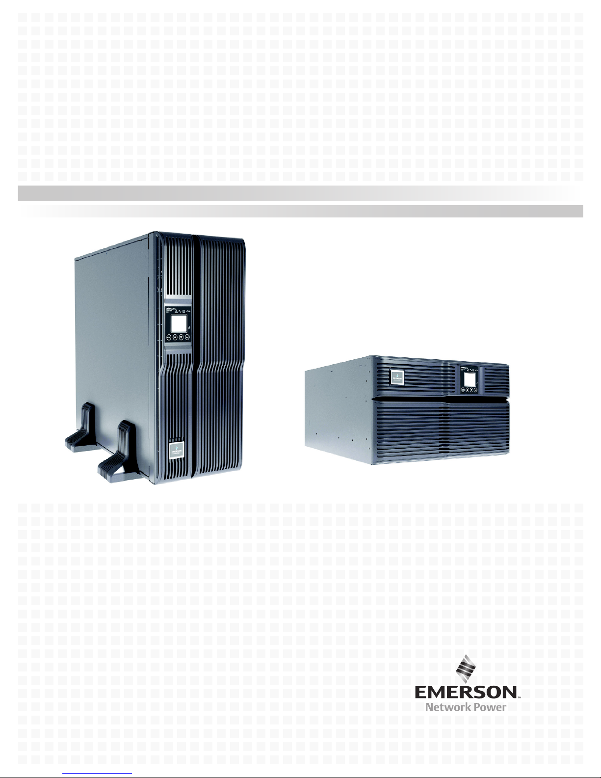
Liebert® GXT4™ 230V, 5000-10,000VA
User Manual


TABLE OF CONTENTS
IMPORTANT SAFETY PRECAUTIONS . . . . . . . . . . . . . . . . . . . . . . . . . . . . . . . . . . . . . . . . . . . . . . . .1
GLOSSARY OF SYMBOLS . . . . . . . . . . . . . . . . . . . . . . . . . . . . . . . . . . . . . . . . . . . . . . . . . . . . . . .3
1.0 PRODUCT DESCRIPTION . . . . . . . . . . . . . . . . . . . . . . . . . . . . . . . . . . . . . . . . . . . . . . . . . . .4
1.1 Features . . . . . . . . . . . . . . . . . . . . . . . . . . . . . . . . . . . . . . . . . . . . . . . . . . . . . . . . . . . . . . . . . . . 4
1.2 Available Models . . . . . . . . . . . . . . . . . . . . . . . . . . . . . . . . . . . . . . . . . . . . . . . . . . . . . . . . . . . . 4
1.3 Appearance and Components . . . . . . . . . . . . . . . . . . . . . . . . . . . . . . . . . . . . . . . . . . . . . . . . . . 5
1.3.1 Appearance . . . . . . . . . . . . . . . . . . . . . . . . . . . . . . . . . . . . . . . . . . . . . . . . . . . . . . . . . . . . . . . . . . 5
1.3.2 Rear Panel Features. . . . . . . . . . . . . . . . . . . . . . . . . . . . . . . . . . . . . . . . . . . . . . . . . . . . . . . . . . . 6
1.4 Internal Battery Packs. . . . . . . . . . . . . . . . . . . . . . . . . . . . . . . . . . . . . . . . . . . . . . . . . . . . . . . . 7
1.5 Removable Power Distribution Box. . . . . . . . . . . . . . . . . . . . . . . . . . . . . . . . . . . . . . . . . . . . . . 7
1.6 Major Components . . . . . . . . . . . . . . . . . . . . . . . . . . . . . . . . . . . . . . . . . . . . . . . . . . . . . . . . . . . 8
1.6.1 Transient Voltage Surge Suppression (TVSS) and EMI/RFI Filters. . . . . . . . . . . . . . . . . . . . . 8
1.6.2 Rectifier/Power Factor Correction (PFC) Circuit . . . . . . . . . . . . . . . . . . . . . . . . . . . . . . . . . . . . 8
1.6.3 Inverter . . . . . . . . . . . . . . . . . . . . . . . . . . . . . . . . . . . . . . . . . . . . . . . . . . . . . . . . . . . . . . . . . . . . . 8
1.6.4 Battery Charger . . . . . . . . . . . . . . . . . . . . . . . . . . . . . . . . . . . . . . . . . . . . . . . . . . . . . . . . . . . . . . 8
1.6.5 DC-to-DC Converter . . . . . . . . . . . . . . . . . . . . . . . . . . . . . . . . . . . . . . . . . . . . . . . . . . . . . . . . . . . 8
1.6.6 Battery . . . . . . . . . . . . . . . . . . . . . . . . . . . . . . . . . . . . . . . . . . . . . . . . . . . . . . . . . . . . . . . . . . . . . 9
1.6.7 Internal Bypass . . . . . . . . . . . . . . . . . . . . . . . . . . . . . . . . . . . . . . . . . . . . . . . . . . . . . . . . . . . . . . 9
1.6.8 Maintenance Bypass. . . . . . . . . . . . . . . . . . . . . . . . . . . . . . . . . . . . . . . . . . . . . . . . . . . . . . . . . . . 9
1.7 Operating Mode . . . . . . . . . . . . . . . . . . . . . . . . . . . . . . . . . . . . . . . . . . . . . . . . . . . . . . . . . . . . . 9
1.7.1 Mains Mode. . . . . . . . . . . . . . . . . . . . . . . . . . . . . . . . . . . . . . . . . . . . . . . . . . . . . . . . . . . . . . . . . . 9
1.7.2 Manual Bypass Mode . . . . . . . . . . . . . . . . . . . . . . . . . . . . . . . . . . . . . . . . . . . . . . . . . . . . . . . . . . 9
1.7.3 Battery Mode . . . . . . . . . . . . . . . . . . . . . . . . . . . . . . . . . . . . . . . . . . . . . . . . . . . . . . . . . . . . . . . 10
1.7.4 Battery Recharge Mode . . . . . . . . . . . . . . . . . . . . . . . . . . . . . . . . . . . . . . . . . . . . . . . . . . . . . . . 10
1.7.5 Frequency Converter Mode . . . . . . . . . . . . . . . . . . . . . . . . . . . . . . . . . . . . . . . . . . . . . . . . . . . . 10
1.7.6 Active ECO Mode . . . . . . . . . . . . . . . . . . . . . . . . . . . . . . . . . . . . . . . . . . . . . . . . . . . . . . . . . . . . 10
2.0 INSTALLATION . . . . . . . . . . . . . . . . . . . . . . . . . . . . . . . . . . . . . . . . . . . . . . . . . . . . . . . . . 11
2.1 Unpacking and Inspection . . . . . . . . . . . . . . . . . . . . . . . . . . . . . . . . . . . . . . . . . . . . . . . . . . . . 11
2.2 What’s Included . . . . . . . . . . . . . . . . . . . . . . . . . . . . . . . . . . . . . . . . . . . . . . . . . . . . . . . . . . . . 11
2.3 Preparation for Installation . . . . . . . . . . . . . . . . . . . . . . . . . . . . . . . . . . . . . . . . . . . . . . . . . . . 11
2.3.1 Installation Environment. . . . . . . . . . . . . . . . . . . . . . . . . . . . . . . . . . . . . . . . . . . . . . . . . . . . . . 11
2.4 Install the Main Cabinet . . . . . . . . . . . . . . . . . . . . . . . . . . . . . . . . . . . . . . . . . . . . . . . . . . . . . 12
2.4.1 Tower UPS Installation . . . . . . . . . . . . . . . . . . . . . . . . . . . . . . . . . . . . . . . . . . . . . . . . . . . . . . . 12
2.4.2 Rack Installation . . . . . . . . . . . . . . . . . . . . . . . . . . . . . . . . . . . . . . . . . . . . . . . . . . . . . . . . . . . . 13
2.4.3 External Battery Cabinet Installation . . . . . . . . . . . . . . . . . . . . . . . . . . . . . . . . . . . . . . . . . . . 13
2.5 Connect Input/Output Power. . . . . . . . . . . . . . . . . . . . . . . . . . . . . . . . . . . . . . . . . . . . . . . . . . 14
2.5.1 Distribution Box Electrical Connections. . . . . . . . . . . . . . . . . . . . . . . . . . . . . . . . . . . . . . . . . . 15
2.6 IT Power System Configuration . . . . . . . . . . . . . . . . . . . . . . . . . . . . . . . . . . . . . . . . . . . . . . . 16
3.0 OPERATION AND DISPLAY PANEL . . . . . . . . . . . . . . . . . . . . . . . . . . . . . . . . . . . . . . . . . . .17
3.1 LED Indicators . . . . . . . . . . . . . . . . . . . . . . . . . . . . . . . . . . . . . . . . . . . . . . . . . . . . . . . . . . . . . 17
3.2 Control Buttons . . . . . . . . . . . . . . . . . . . . . . . . . . . . . . . . . . . . . . . . . . . . . . . . . . . . . . . . . . . . 18
3.3 LCD . . . . . . . . . . . . . . . . . . . . . . . . . . . . . . . . . . . . . . . . . . . . . . . . . . . . . . . . . . . . . . . . . . . . . . 18
i

3.4 Menu Structure . . . . . . . . . . . . . . . . . . . . . . . . . . . . . . . . . . . . . . . . . . . . . . . . . . . . . . . . . . . . 18
3.4.1 Startup Screen . . . . . . . . . . . . . . . . . . . . . . . . . . . . . . . . . . . . . . . . . . . . . . . . . . . . . . . . . . . . . . 20
3.4.2 Default Screen . . . . . . . . . . . . . . . . . . . . . . . . . . . . . . . . . . . . . . . . . . . . . . . . . . . . . . . . . . . . . . 21
3.4.3 Main Menu Screen . . . . . . . . . . . . . . . . . . . . . . . . . . . . . . . . . . . . . . . . . . . . . . . . . . . . . . . . . . . 21
3.4.4 Prompt List . . . . . . . . . . . . . . . . . . . . . . . . . . . . . . . . . . . . . . . . . . . . . . . . . . . . . . . . . . . . . . . . . 29
3.4.5 Warning List . . . . . . . . . . . . . . . . . . . . . . . . . . . . . . . . . . . . . . . . . . . . . . . . . . . . . . . . . . . . . . . . 30
3.4.6 Fault List . . . . . . . . . . . . . . . . . . . . . . . . . . . . . . . . . . . . . . . . . . . . . . . . . . . . . . . . . . . . . . . . . . 30
4.0 OPERATION . . . . . . . . . . . . . . . . . . . . . . . . . . . . . . . . . . . . . . . . . . . . . . . . . . . . . . . . . . .31
4.1 Startup Checklist for the Liebert GXT4 . . . . . . . . . . . . . . . . . . . . . . . . . . . . . . . . . . . . . . . . . 31
4.2 Starting the UPS . . . . . . . . . . . . . . . . . . . . . . . . . . . . . . . . . . . . . . . . . . . . . . . . . . . . . . . . . . . 31
4.3 Manual Battery Test . . . . . . . . . . . . . . . . . . . . . . . . . . . . . . . . . . . . . . . . . . . . . . . . . . . . . . . . 31
4.4 Manual Bypass . . . . . . . . . . . . . . . . . . . . . . . . . . . . . . . . . . . . . . . . . . . . . . . . . . . . . . . . . . . . . 31
4.5 Shut Down the Liebert GXT4 . . . . . . . . . . . . . . . . . . . . . . . . . . . . . . . . . . . . . . . . . . . . . . . . . 31
4.6 Disconnecting Input Power from the Liebert GXT4. . . . . . . . . . . . . . . . . . . . . . . . . . . . . . . . 32
4.7 Maintenance Bypass . . . . . . . . . . . . . . . . . . . . . . . . . . . . . . . . . . . . . . . . . . . . . . . . . . . . . . . . 32
5.0 COMMUNICATION . . . . . . . . . . . . . . . . . . . . . . . . . . . . . . . . . . . . . . . . . . . . . . . . . . . . . . . 33
5.1 Liebert IntelliSlot® Communication Cards. . . . . . . . . . . . . . . . . . . . . . . . . . . . . . . . . . . . . . . 33
5.1.1 Liebert MultiLink . . . . . . . . . . . . . . . . . . . . . . . . . . . . . . . . . . . . . . . . . . . . . . . . . . . . . . . . . . . . 33
5.2 USB Port Communication . . . . . . . . . . . . . . . . . . . . . . . . . . . . . . . . . . . . . . . . . . . . . . . . . . . . 33
5.2.1 Configuration Program . . . . . . . . . . . . . . . . . . . . . . . . . . . . . . . . . . . . . . . . . . . . . . . . . . . . . . . 34
5.3 Terminal Block Communication . . . . . . . . . . . . . . . . . . . . . . . . . . . . . . . . . . . . . . . . . . . . . . . 35
5.3.1 Any Mode Shutdown . . . . . . . . . . . . . . . . . . . . . . . . . . . . . . . . . . . . . . . . . . . . . . . . . . . . . . . . . 35
5.3.2 Battery Mode Shutdown . . . . . . . . . . . . . . . . . . . . . . . . . . . . . . . . . . . . . . . . . . . . . . . . . . . . . . 36
5.3.3 On Battery . . . . . . . . . . . . . . . . . . . . . . . . . . . . . . . . . . . . . . . . . . . . . . . . . . . . . . . . . . . . . . . . . 36
5.3.4 Low Battery . . . . . . . . . . . . . . . . . . . . . . . . . . . . . . . . . . . . . . . . . . . . . . . . . . . . . . . . . . . . . . . . 36
5.4 Remote Emergency Power Off . . . . . . . . . . . . . . . . . . . . . . . . . . . . . . . . . . . . . . . . . . . . . . . . . 37
6.0 MAINTENANCE . . . . . . . . . . . . . . . . . . . . . . . . . . . . . . . . . . . . . . . . . . . . . . . . . . . . . . . . .38
6.1 Replacing the Internal Battery Pack. . . . . . . . . . . . . . . . . . . . . . . . . . . . . . . . . . . . . . . . . . . . 38
6.1.1 Battery Replacement Procedures . . . . . . . . . . . . . . . . . . . . . . . . . . . . . . . . . . . . . . . . . . . . . . . 38
6.2 Battery Charging . . . . . . . . . . . . . . . . . . . . . . . . . . . . . . . . . . . . . . . . . . . . . . . . . . . . . . . . . . . 39
6.3 Precautions . . . . . . . . . . . . . . . . . . . . . . . . . . . . . . . . . . . . . . . . . . . . . . . . . . . . . . . . . . . . . . . . 39
6.4 Checking UPS Status . . . . . . . . . . . . . . . . . . . . . . . . . . . . . . . . . . . . . . . . . . . . . . . . . . . . . . . . 40
6.5 Checking UPS Functions . . . . . . . . . . . . . . . . . . . . . . . . . . . . . . . . . . . . . . . . . . . . . . . . . . . . . 40
7.0 TROUBLESHOOTING . . . . . . . . . . . . . . . . . . . . . . . . . . . . . . . . . . . . . . . . . . . . . . . . . . . . . 41
7.1 UPS Symptoms. . . . . . . . . . . . . . . . . . . . . . . . . . . . . . . . . . . . . . . . . . . . . . . . . . . . . . . . . . . . . 41
7.1.1 Indicator and LCD . . . . . . . . . . . . . . . . . . . . . . . . . . . . . . . . . . . . . . . . . . . . . . . . . . . . . . . . . . . 41
7.1.2 Audible Alarm. . . . . . . . . . . . . . . . . . . . . . . . . . . . . . . . . . . . . . . . . . . . . . . . . . . . . . . . . . . . . . . 42
7.2 Troubleshooting—Problems, Causes, Solutions . . . . . . . . . . . . . . . . . . . . . . . . . . . . . . . . . . . 42
8.0 SPECIFICATIONS. . . . . . . . . . . . . . . . . . . . . . . . . . . . . . . . . . . . . . . . . . . . . . . . . . . . . . . .43
8.1 Auto-Learning Battery Run Times . . . . . . . . . . . . . . . . . . . . . . . . . . . . . . . . . . . . . . . . . . . . . 48
8.2 Product Warranty Registration . . . . . . . . . . . . . . . . . . . . . . . . . . . . . . . . . . . . . . . . . . . . . . . . 48
8.3 Technical Support. . . . . . . . . . . . . . . . . . . . . . . . . . . . . . . . . . . . . . . . . . . . . . . . . . . . . . . . . . . 48
ii

FIGURES
Figure 1 Liebert GXT4 5000VA and 6000VA, front view . . . . . . . . . . . . . . . . . . . . . . . . . . . . . . . . . . . . . . . . 5
Figure 2 Liebert GXT4, rear view—5000 and 6000VA . . . . . . . . . . . . . . . . . . . . . . . . . . . . . . . . . . . . . . . . . . 6
Figure 3 Liebert GXT4, rear view—10,000VA . . . . . . . . . . . . . . . . . . . . . . . . . . . . . . . . . . . . . . . . . . . . . . . . . 6
Figure 4 Internal battery pack with connector . . . . . . . . . . . . . . . . . . . . . . . . . . . . . . . . . . . . . . . . . . . . . . . . 7
Figure 5 Power distribution box for GXT4 5000VA and 6000VA models . . . . . . . . . . . . . . . . . . . . . . . . . . . . 7
Figure 6 Power distribution box for GXT4 10,000VA model . . . . . . . . . . . . . . . . . . . . . . . . . . . . . . . . . . . . . . 7
Figure 7 Support bases . . . . . . . . . . . . . . . . . . . . . . . . . . . . . . . . . . . . . . . . . . . . . . . . . . . . . . . . . . . . . . . . . . 12
Figure 8 Remove the front plastic bezel cover . . . . . . . . . . . . . . . . . . . . . . . . . . . . . . . . . . . . . . . . . . . . . . . . 12
Figure 9 Rotate the operation and display panel . . . . . . . . . . . . . . . . . . . . . . . . . . . . . . . . . . . . . . . . . . . . . . 12
Figure 10 External battery cabinets connected to 10,000VA Liebert GXT4 . . . . . . . . . . . . . . . . . . . . . . . . . 13
Figure 11 Power Distribution box removal—captive screws and maintenance bypass breaker . . . . . . . . . . 14
Figure 12 Distribution box electrical connections diagram. . . . . . . . . . . . . . . . . . . . . . . . . . . . . . . . . . . . . . . 15
Figure 13 Terminal block connections—PD2-CE6HDWRMBS and PD2-CE10HDWRMBS. . . . . . . . . . . . . 15
Figure 14 Remove cover from IT Power System Connectors compartment . . . . . . . . . . . . . . . . . . . . . . . . . . 16
Figure 15 Operation and display panel . . . . . . . . . . . . . . . . . . . . . . . . . . . . . . . . . . . . . . . . . . . . . . . . . . . . . . 17
Figure 16 Menu structure . . . . . . . . . . . . . . . . . . . . . . . . . . . . . . . . . . . . . . . . . . . . . . . . . . . . . . . . . . . . . . . . . 19
Figure 17 Startup screen . . . . . . . . . . . . . . . . . . . . . . . . . . . . . . . . . . . . . . . . . . . . . . . . . . . . . . . . . . . . . . . . . . 20
Figure 18 Startup screens . . . . . . . . . . . . . . . . . . . . . . . . . . . . . . . . . . . . . . . . . . . . . . . . . . . . . . . . . . . . . . . . . 20
Figure 19 Starting and Start Successful screens . . . . . . . . . . . . . . . . . . . . . . . . . . . . . . . . . . . . . . . . . . . . . . . 20
Figure 20 Default screen . . . . . . . . . . . . . . . . . . . . . . . . . . . . . . . . . . . . . . . . . . . . . . . . . . . . . . . . . . . . . . . . . . 21
Figure 21 Main Menu screen. . . . . . . . . . . . . . . . . . . . . . . . . . . . . . . . . . . . . . . . . . . . . . . . . . . . . . . . . . . . . . . 21
Figure 22 Status screens . . . . . . . . . . . . . . . . . . . . . . . . . . . . . . . . . . . . . . . . . . . . . . . . . . . . . . . . . . . . . . . . . . 22
Figure 23 CONFIGURATION screen . . . . . . . . . . . . . . . . . . . . . . . . . . . . . . . . . . . . . . . . . . . . . . . . . . . . . . . . 22
Figure 24 UPS screens. . . . . . . . . . . . . . . . . . . . . . . . . . . . . . . . . . . . . . . . . . . . . . . . . . . . . . . . . . . . . . . . . . . . 23
Figure 25 Parallel screen—10kVA units only . . . . . . . . . . . . . . . . . . . . . . . . . . . . . . . . . . . . . . . . . . . . . . . . . 23
Figure 26 Battery screen . . . . . . . . . . . . . . . . . . . . . . . . . . . . . . . . . . . . . . . . . . . . . . . . . . . . . . . . . . . . . . . . . . 24
Figure 27 ECO Mode screen . . . . . . . . . . . . . . . . . . . . . . . . . . . . . . . . . . . . . . . . . . . . . . . . . . . . . . . . . . . . . . . 24
Figure 28 LCD screen . . . . . . . . . . . . . . . . . . . . . . . . . . . . . . . . . . . . . . . . . . . . . . . . . . . . . . . . . . . . . . . . . . . . 25
Figure 29 Language screen . . . . . . . . . . . . . . . . . . . . . . . . . . . . . . . . . . . . . . . . . . . . . . . . . . . . . . . . . . . . . . . . 25
Figure 30 Color screen . . . . . . . . . . . . . . . . . . . . . . . . . . . . . . . . . . . . . . . . . . . . . . . . . . . . . . . . . . . . . . . . . . . . 25
Figure 31 Factory Default screen . . . . . . . . . . . . . . . . . . . . . . . . . . . . . . . . . . . . . . . . . . . . . . . . . . . . . . . . . . . 26
Figure 32 Control screen . . . . . . . . . . . . . . . . . . . . . . . . . . . . . . . . . . . . . . . . . . . . . . . . . . . . . . . . . . . . . . . . . . 26
Figure 33 Turn UPS On or Off screen . . . . . . . . . . . . . . . . . . . . . . . . . . . . . . . . . . . . . . . . . . . . . . . . . . . . . . . 26
Figure 34 Alarm Control screen . . . . . . . . . . . . . . . . . . . . . . . . . . . . . . . . . . . . . . . . . . . . . . . . . . . . . . . . . . . . 27
Figure 35 Batt Test screen . . . . . . . . . . . . . . . . . . . . . . . . . . . . . . . . . . . . . . . . . . . . . . . . . . . . . . . . . . . . . . . . 27
Figure 36 Log screens . . . . . . . . . . . . . . . . . . . . . . . . . . . . . . . . . . . . . . . . . . . . . . . . . . . . . . . . . . . . . . . . . . . . 27
Figure 37 Clear Log screen . . . . . . . . . . . . . . . . . . . . . . . . . . . . . . . . . . . . . . . . . . . . . . . . . . . . . . . . . . . . . . . . 28
Figure 38 About screen . . . . . . . . . . . . . . . . . . . . . . . . . . . . . . . . . . . . . . . . . . . . . . . . . . . . . . . . . . . . . . . . . . . 28
Figure 39 Network screens . . . . . . . . . . . . . . . . . . . . . . . . . . . . . . . . . . . . . . . . . . . . . . . . . . . . . . . . . . . . . . . . 29
Figure 40 Terminal Block Communication pin layout. . . . . . . . . . . . . . . . . . . . . . . . . . . . . . . . . . . . . . . . . . . 35
Figure 41 REPO switch connection diagram . . . . . . . . . . . . . . . . . . . . . . . . . . . . . . . . . . . . . . . . . . . . . . . . . . 37
Figure 42 Removing the front plastic bezel cover and battery door . . . . . . . . . . . . . . . . . . . . . . . . . . . . . . . . 38
Figure 43 Disconnecting the battery plug and battery receptacle, front view . . . . . . . . . . . . . . . . . . . . . . . . 38
Figure 44 Pulling out the battery packs . . . . . . . . . . . . . . . . . . . . . . . . . . . . . . . . . . . . . . . . . . . . . . . . . . . . . . 39
iii

TABLES
Table 1 UPS models, power ratings . . . . . . . . . . . . . . . . . . . . . . . . . . . . . . . . . . . . . . . . . . . . . . . . . . . . . . . . 4
Table 2 Branch circuit breaker ratings . . . . . . . . . . . . . . . . . . . . . . . . . . . . . . . . . . . . . . . . . . . . . . . . . . . . . 15
Table 3 Electrical specifications . . . . . . . . . . . . . . . . . . . . . . . . . . . . . . . . . . . . . . . . . . . . . . . . . . . . . . . . . . 15
Table 4 LED indicators . . . . . . . . . . . . . . . . . . . . . . . . . . . . . . . . . . . . . . . . . . . . . . . . . . . . . . . . . . . . . . . . . 17
Table 5 Control buttons . . . . . . . . . . . . . . . . . . . . . . . . . . . . . . . . . . . . . . . . . . . . . . . . . . . . . . . . . . . . . . . . . 18
Table 6 Prompts and meanings . . . . . . . . . . . . . . . . . . . . . . . . . . . . . . . . . . . . . . . . . . . . . . . . . . . . . . . . . . . 29
Table 7 Warning list. . . . . . . . . . . . . . . . . . . . . . . . . . . . . . . . . . . . . . . . . . . . . . . . . . . . . . . . . . . . . . . . . . . . 30
Table 8 Fault list . . . . . . . . . . . . . . . . . . . . . . . . . . . . . . . . . . . . . . . . . . . . . . . . . . . . . . . . . . . . . . . . . . . . . . 30
Table 9 Output voltage option, all models . . . . . . . . . . . . . . . . . . . . . . . . . . . . . . . . . . . . . . . . . . . . . . . . . . 34
Table 10 Description of the displayed fault . . . . . . . . . . . . . . . . . . . . . . . . . . . . . . . . . . . . . . . . . . . . . . . . . . 41
Table 11 Audible alarm description . . . . . . . . . . . . . . . . . . . . . . . . . . . . . . . . . . . . . . . . . . . . . . . . . . . . . . . . 42
Table 12 Troubleshooting. . . . . . . . . . . . . . . . . . . . . . . . . . . . . . . . . . . . . . . . . . . . . . . . . . . . . . . . . . . . . . . . . 42
Table 13 UPS specifications. . . . . . . . . . . . . . . . . . . . . . . . . . . . . . . . . . . . . . . . . . . . . . . . . . . . . . . . . . . . . . . 43
Table 14 Power distribution specifications . . . . . . . . . . . . . . . . . . . . . . . . . . . . . . . . . . . . . . . . . . . . . . . . . . . 44
Table 15 External battery cabinet specifications . . . . . . . . . . . . . . . . . . . . . . . . . . . . . . . . . . . . . . . . . . . . . . 45
Table 16 Battery run time, minutes, all models. . . . . . . . . . . . . . . . . . . . . . . . . . . . . . . . . . . . . . . . . . . . . . . 46
iv

IMPORTANT SAFETY PRECAUTIONS
!
!
WARNING
Risk of electric shock. Can cause equipment damage, injury or death.
Observe all cautions and warnings in this manual. Failure to do so may result in serious
injury or death.
Refer all UPS and battery service to properly trained and qualified service personnel. Do not
attempt to service this product yourself.
Opening or removing the cover may expose you to lethal voltages within this unit even when
it is apparently not operating and the input wiring is disconnected from the electrical source.
Never work alone.
SAVE THESE INSTRUCTIONS
This manual contains important safety instructions that must be followed during the installation and
maintenance of the UPS and batteries. Read this manual thoroughly before attempting to install or
operate this UPS.
UPS Safety Notes
The UPS contains no user-serviceable parts except the internal battery pack. Do not remove the
cover. Removing the cover may result in electric shock and will invalidate any implied warranty.
The UPS has an internal battery, so the output receptacles of the UPS may carry live voltage even if
the UPS is not connected to mains input power.
Before moving or rewiring the UPS, disconnect mains input power and the battery and make sure
that the UPS is completely shut down. Otherwise, the output terminal may carry live voltage,
presenting an electric shock hazard.
To ensure human safety and normal UPS operation, the UPS must be properly grounded before use.
When the UPS is connected to an IT power distribution system, the short-circuit protection device
must be installed on the neutral line.
Install and use the UPS in the following environments:
• Temperature: 0°C to 40°C (32 - 104°F); relative humidity: 0% to 95%, non-condensing)
• Out of direct sunlight
• Away from heat source
• Stable surface, not subject to vibrations or shocks
• Away from dust and other particulates
• Away from corrosive substances, salts and flammable gases
Keep the air inlet and outlet of the UPS unobstructed. Poor ventilation will increase the UPS internal
temperature and can shorten the life of the UPS and its batteries.
Keep liquid and other foreign objects away from the UPS.
This UPS is not intended for use with life support and other designated critical devices. Maximum
load must not exceed that shown on the UPS rating label. This UPS is designed for data processing
equipment. If uncertain, consult your local dealer or Emerson Network Power
®
representative.
Battery Safety
WARNING
Risk of electric shock and explosion. Can cause equipment damage, injury and death.
Do not dispose of the battery in a fire. The battery may explode.
Do not open or damage the battery. Released electrolyte is toxic and is harmful to skin and
eyes. If electrolyte comes into contact with the skin, wash the affected area immediately with
plenty of clean water and get medical attention.
1Liebert
®
GXT4
™

!
WARNING
Risk of electric shock. Can cause equipment damage, injury and death.
A battery can present a risk of electrical shock and high short-circuit current. The following
precautions should be observed when working on batteries:
• Remove watches, rings and other metal objects.
• Use tools with insulated handles.
• Wear rubber gloves and boots.
• Do not lay tools or metal parts on top of batteries.
• Disconnect charging source prior to connecting or disconnecting battery terminals.
• Determine if the battery is inadvertently grounded. If it is inadvertently grounded, remove
the source of the ground. Contact with any part of a grounded battery can result in
electrical shock. The likelihood of such shock will be reduced if grounds are removed during
installation and maintenance (applicable to a UPS and a remote battery supply not having
a grounded supply circuit).
ELECTROMAGNETIC COMPATIBILITY—The Liebert GXT4 series complies with the limits for a
Class A digital device. Operating this device in a residential area is likely to cause harmful
interference that users must correct at their own expense.
The Liebert GXT4 series complies with the requirements of EMC Directive 2004/108/EC and the
published technical standards. Continued compliance requires installation in accordance with these
instructions and use of accessories approved by Emerson
Information for the Protection of the Environment
UPS SERVICING—This UPS makes use of components dangerous for the environment (electronic
cards, electronic components). The components removed must be taken to specialized collection and
disposal centers.
®
.
NOTICE TO EUROPEAN UNION CUSTOMERS: DISPOSAL OF OLD APPLIANCES—This
product has been supplied from an environmentally aware manufacturer that complies with the
Waste Electrical and Electronic Equipment (WEEE) Directive 2002/96/CE.
The “crossed-out wheelie bin” symbol at right is placed on this product to
encourage you to recycle wherever possible. Please be environmentally
responsible and recycle this product through your recycling facility at its end
of life. Do not dispose of this product as unsorted municipal waste. Follow
local municipal waste ordinances for proper disposal provisions to reduce the
environmental impact of waste electrical and electronic equipment (WEEE).
For information regarding the scrapping of this equipment, browse
www.eu.emersonnetworkpower.com (“Products session” or “Contact us”
session) or call our worldwide technical support.
• Toll Free: 00 80011554499
• Toll Number Based in Italy: +39 0298250222
Liebert® GXT4
™
2

GLOSSARY OF SYMBOLS
!
PbH2SO4
-
+
R
Risk of electrical shock
Indicates caution followed by important instructions
AC input
AC output
i
Requests the user to consult the manual
Indicates the unit contains a valve-regulated lead acid battery
Recycle
DC voltage
Equipment grounding conductor
Bonded to ground
AC voltage
WEEE
3Liebert
®
GXT4
™

1.0 PRODUCT DESCRIPTION
The Liebert GXT4 is a compact, online uninterruptible power system (UPS) that continuously
conditions and regulates its output voltage. The UPS is designed to supply microcomputers and other
sensitive electronic equipment with clean sine wave input power, 5000VA, 6000VA and 10,000VA at
230V.
Upon generation, AC power is clean and stable. However, during transmission and distribution it is
subject to voltage sags, spikes and complete failure that may interrupt computer operations, cause
data loss and damage equipment.
The Liebert GXT4 protects equipment from these disturbances. The Liebert GXT4 continuously
charges its batteries from the mains, enabling it to supply power to connected loads, even when the
mains fail.
This section describes the UPS, its features, models, appearance and components, operating
principles and operating mode.
1.1 Features
The UPS includes these features:
• Intelligent battery management to extend battery life
• LCD for user-friendly operation and local monitoring and configuration of operational parameters
• Flexible network management with Liebert MultiLink
• Fan fault self-inspection and automated diagnostic function
• Intelligent fan operation, automatically changing rotation speed depending on system
requirements, to decrease power consumption and noise
• Input circuit breaker to ease recovery from overloads
• CE mark and safety approval from CE
• Communication options: USB port, Liebert IntelliSlot
• Dry contacts for remote monitoring
• Input power factor greater than 0.99
• Output voltage selection function
Product Description
®
software
®
port and terminal block communication
1.2 Available Models
Available models of the UPS are listed in Table 1:
Table 1 UPS models, power ratings
Model Number
GXT4-5000RT230
GXT4-5000RT230E
GXT4-6000RT230
GXT4-6000RT230E
GXT4-10000RT230
GXT4-10000RT230E
Nominal Power Rating
5000VA / 4000W
6000VA / 4800W
10000VA / 9000W
Liebert® GXT4
™
4

1.3 Appearance and Components
Lower Bezel and
Battery Access
Door
Upper Bezel
Upper Bezel
Operation and
Display Panel
10,000VA model front
layout is identical.
The 10,000VA unit’s battery
compartment is larger.
1.3.1 Appearance
The Liebert GXT4 rack/tower models in various power ratings have the same general appearance,
controls and features (see Figure 1). The various rack/tower models differ largely in the type of
receptacles each has.
Figure 1 Liebert GXT4 5000VA and 6000VA, front view
Product Description
5Liebert
®
GXT4
™
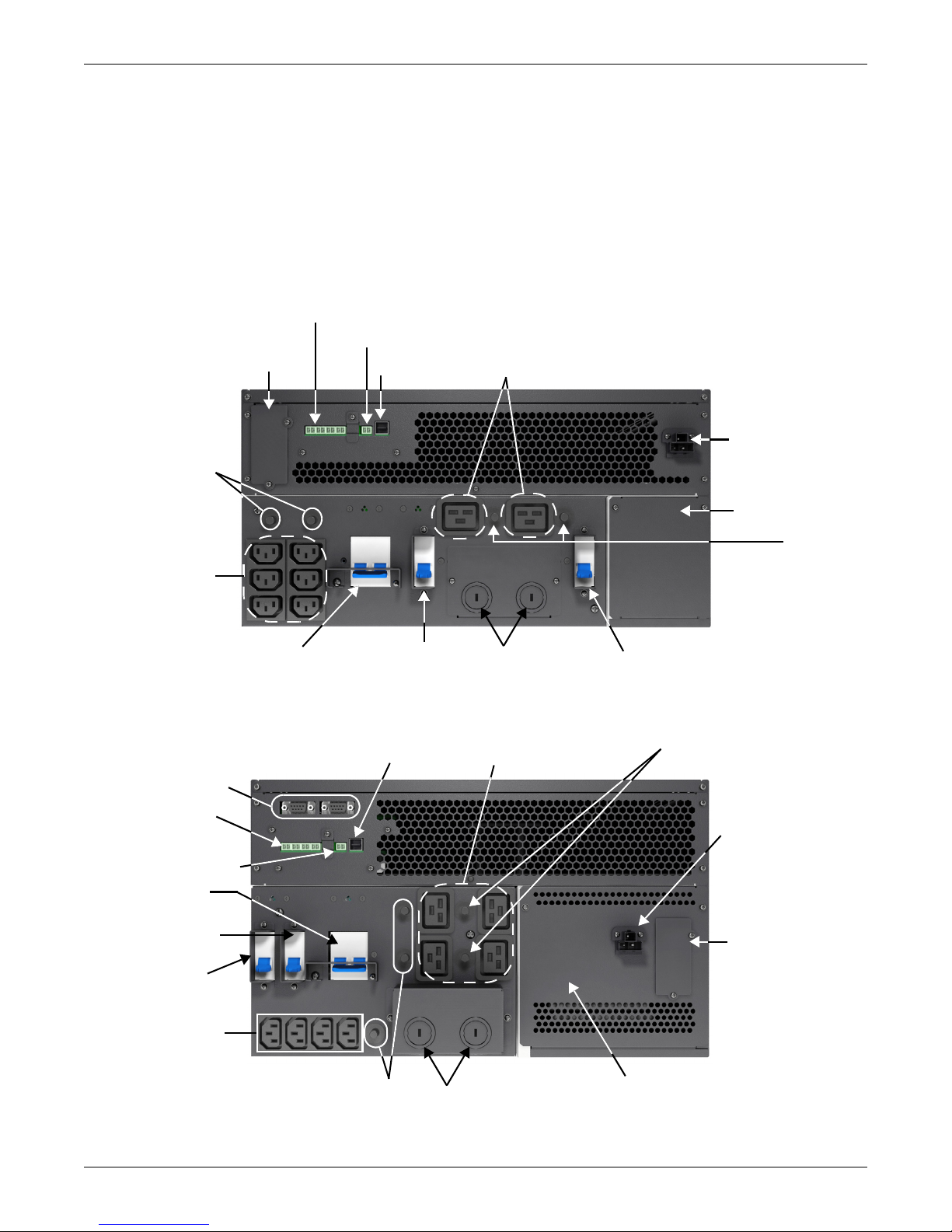
1.3.2 Rear Panel Features
External Battery
Connector
IT Power System
Access Cover
C13 Output
Receptacles
C19 Output Power
Receptacles
Liebert IntelliSlot
®
Port
USB Port
Terminal Block
Communication
Maintenance
Bypass Breaker
Output
Circuit
Breaker
Knockouts
for Hard-wired
Power Input
Input Circuit
Breaker
Liebert GXT4, 5000 & 6000VA
Removable Power
Distribution Box
factory-attached in
bottom-left corner
Output Circuit
Breakers
REPO
Output
Circuit
Breakers
External Battery
Connector
Removable Power Distribution
Box factory-attached in
bottom-left corner
C13 Output
Receptacles
C19 Output
Receptacles
Liebert
IntelliSlot
Port
USB Port
Terminal Block
Communication
Knockouts
for Hard-Wired
Power Input
DB9 Ports (Parallel
Communication)
Input Circuit
Breaker
Maintenance
Bypass Breaker
Output Circuit
Breaker
REPO
External Battery
Connector
IT Power System
Access Cover
Output
Circuit
Breakers
Output Circuit Breakers
The rear panel of the Liebert GXT4 has these features:
• Liebert IntelliSlot
• USB port • Terminal Block Communication
• Input Circuit Breaker • Output Circuit Breakers
• General Output Receptacles • Maintenance Bypass Circuit Breaker
• External Battery Connector
Figure 2 Liebert GXT4, rear view—5000 and 6000VA
®
Port • Cooling Fan
Product Description
Figure 3 Liebert GXT4, rear view—10,000VA
Liebert® GXT4
™
6
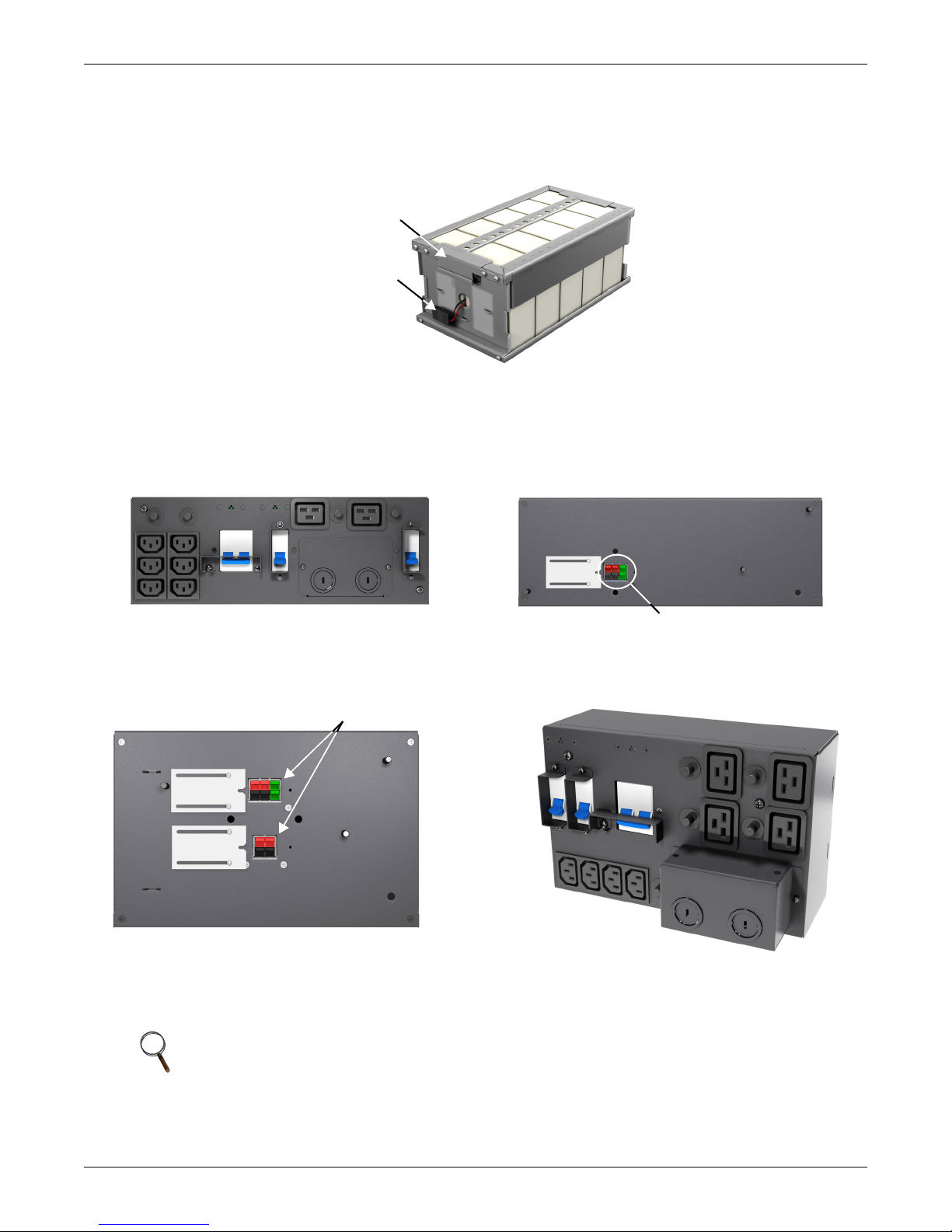
1.4 Internal Battery Packs
Battery Connector
Front of Battery Pack
GXT4 10,000 Battery
Pack shown; 5000 and
6000VA battery packs
have same features
Battery Handle
Outer Surface View Power Distribution
Box for 5000VA and 6000VA models
PD2-CE6HDWRMBS
Quick-Connect
Front View
Power Distribution Box for 10000VA model
PD2-CE10HDWRMBS
Inner Surface View
Power Distribution Box for 10000VA model
PD2-CE10HDWRMBS
Quick-Connects
The UPS has two internal battery packs behind a battery access door on the front of the unit. Each
internal battery pack is fitted with a connector to link to the UPS.
Figure 4 Internal battery pack with connector
1.5 Removable Power Distribution Box
The UPS arrives with a power distribution pack installed. This box always contains the UPS input
circuit breaker.
Product Description
Figure 5
Power distribution box for GXT4 5000VA and 6000VA models
Figure 6 Power distribution box for GXT4 10,000VA model
NOTE
Hard-wired and hard-wired/receptacle boxes that include a manual bypass switch
allow AC power to continue to flow from the mains input to the load while the box is
removed from the UPS. For details, refer to 2.5 - Connect Input/Output Power.
7Liebert
®
GXT4
™

1.6 Major Components
TVSS
EMI/RFI
Input
Filter
EMI/RFI
Output
Filter
Rectifier /
PFC
DC-DC
Converter
Battery
Dynamic
Bypass
L
G
N
N
G
L
General
Outlet POD
Dependent
Battery
Charger
Inverter
General
Outlet POD
Dependent
General
Outlet POD
Dependent
General
Outlet POD
Dependent
The UPS is composed of mains input, TVSS and EMI/RFI filters, rectifier/PFC, inverter, battery
charger, DC-to-DC converter, battery, dynamic bypass and UPS output.
1.6.1 Transient Voltage Surge Suppression (TVSS) and EMI/RFI Filters
Product Description
These UPS components provide surge protection and filter both electromagnetic interference (EMI)
and radio frequency interference (RFI). They minimize any surges or interference present in the
mains line and keep the sensitive equipment protected.
1.6.2 Rectifier/Power Factor Correction (PFC) Circuit
In normal operation, the rectifier/power factor correction (PFC) circuit converts mains AC power to
regulated DC power for use by the inverter while ensuring that the waveshape of the input current
used by the UPS is near ideal. Extracting this sinewave input current achieves two objectives:
• The mains power is used as efficiently as possible by the UPS.
• The amount of distortion reflected on the mains is reduced.
This results in cleaner power being available to other devices in the building not being protected by
the Liebert GXT4.
1.6.3 Inverter
In normal operation, the inverter utilizes the DC output of the power factor correction circuit and
inverts it into precise, regulated sinewave AC power. Upon a mains power failure, the inverter
receives its required energy from the battery through the DC-to-DC converter. In both modes of
operation, the UPS inverter is on-line and continuously generating clean, precise, regulated AC
output power.
1.6.4 Battery Charger
The battery charger utilizes energy from the mains power and precisely regulates it to continuously
float charge the batteries. The batteries are being charged whenever the Liebert GXT4 is connected to
mains power.
1.6.5 DC-to-DC Converter
The DC-to-DC converter utilizes energy from the battery system and raises the DC voltage to the
optimum operating voltage for the inverter. This allows the inverter to operate continuously at its
optimum efficiency and voltage, thus increasing reliability.
Liebert® GXT4
™
8

1.6.6 Battery
The Liebert GXT4 utilizes valve-regulated, nonspillable, lead acid batteries. To maintain battery
design life, operate the UPS in an ambient temperature of 15°C to 25°C (59°F to 77°F). Optional
external battery cabinets are available to extend battery run times. For run times, see Table 16.
1.6.7 Internal Bypass
The Liebert GXT4 provides an alternate path for mains power to the connected load in the unlikely
event of a UPS malfunction. Should the UPS have an overload, overtemperature or any other UPS
failure condition, the UPS automatically transfers the connected load to bypass. Bypass operation is
indicated by an audible alarm and illuminated amber Bypass LED (other LEDs may be illuminated to
indicate the diagnosed problem). To manually transfer the connected load from the inverter to bypass,
press the Standby/Manual Bypass button once and hold it for about 2 seconds
1.6.8 Maintenance Bypass
The Liebert GXT4 provides a manual maintenance bypass that is located in a removable section of the
rear of the UPS. This allows replacement of the UPS, in the unlikely event of a UPS malfunction,
while keeping the connected equipment powered with mains power.
NOTE
The bypass power path does NOT protect the connected equipment from disturbances
in the mains supply.
Product Description
1.7 Operating Mode
The UPS operation modes include the following: Mains (AC) Mode, Bypass Mode, Battery Mode,
Battery Recharge Mode, Active ECO Mode and Frequency Converter Mode.
Refer to 3.0 - Operation and Display Panel for details about the operating mode indicators and
control buttons.
1.7.1 Mains Mode
During Mains Mode, the mains provides input power to the Liebert GXT4. The filters, PFC circuit
and inverter process this power to provide high-quality sine wave power to connected loads. The UPS
maintains the batteries in a fully charged state.
1.7.2 Manual Bypass Mode
Manual Bypass Mode occurs when the unit is manually placed in internal bypass by navigating the
LCD display menu to select 3 Control > 1 Turn On & Off > Turn UPS Bypass. Bypass operation is
indicated by an audible alarm and illuminated amber bypass indicator. (If other indicators are
illuminated, refer to 7.0 - Troubleshooting). During Bypass Mode, mains power bypasses the
inverter and provides energy to the connected load.
NOTICE
Risk of loss of power to the connected load. Can cause equipment damage.
Turning Off the UPS in Bypass Mode will result in loss of output power to the connected load.
9Liebert
®
GXT4
™

1.7.3 Battery Mode
!
The Liebert GXT4 enters Battery Mode when mains power fails or is outside acceptable limits. The
battery system supplies power through the DC-to-DC converter to the inverter to generate clean AC
power for the connected loads.
When the Liebert GXT4 enters Battery Mode, the UPS sounds a half-second beep at 10-second
intervals. When approximately 2 minutes of run time remains, the beeps sound every 5 seconds to
warn that the battery is getting low (this Low Battery Warning is user-configurable).
In Battery Mode, the battery indicator will illuminate and the LCD will show the prompt utility power
not available.
Press either the Up or Down button once, then press the Enter button to clear the prompt and silence
the audible alarm. Once the alarm has been acknowledged, the screen showing the estimated battery
run time and battery capacity will be visible. Refer to 7.0 - Troubleshooting.
For approximate battery run times, refer to Table 16.
NOTICE
Risk of loss of power to the connected load. Can cause equipment damage.
Turning Off the Liebert GXT4 when it is in Battery Mode will result in loss of output power to
the connected load.
If the UPS is turned Off manually, it must be manually restarted after mains power returns.
If the UPS is turned Off by a communication signal or because the batteries are depleted, it
will operate as set in the configuration program for Auto-Restart (Refer to 5.2.1 -
Configuration Program).
Product Description
1.7.4 Battery Recharge Mode
Once mains power is applied to the Liebert GXT4, the Battery Charger begins charging the batteries.
1.7.5 Frequency Converter Mode
All models of the Liebert GXT4 are capable of frequency conversion. Frequency Conversion Mode can
be selected using the configuration program. Allowable frequency operating modes include:
• Auto Sensing - 50Hz or 60Hz – Bypass Enabled
• Auto Sensing - 50Hz or 60Hz – Bypass Disabled
• Frequency Converter - 50Hz – Bypass Disabled
• Frequency Converter - 60Hz – Bypass Disabled
NOTE
The default for all models of the Liebert GXT4 is “Auto Sensing - 50Hz or 60Hz – Bypass
Enabled.”
CAUTION
Risk of electric shock. Can cause injury or death.
Never touch the AC input receptacle while the UPS is operating. Voltage may still be present
even when the AC input indicator is Off.
1.7.6 Active ECO Mode
All Liebert GXT4 models can operate in Active ECO Mode. In this mode, the connected equipment is
powered through the bypass path to increase efficiency, reducing the electrical costs.
Active ECO mode keeps the rectifier and inverter operating, allowing the inverter to remain
synchronized to bypass. This synchronization allows the transfer of the connected equipment to UPS
inverter power almost seamlessly if bypass power falls outside the user-set limits. Once bypass power
returns within the acceptable parameters, the UPS will return to Active ECO Mode operation.
The default setting is Active ECO Mode Off.
Liebert® GXT4
™
10

2.0 INSTALLATION
!
Do NOT attempt to start the UPS, turn On any circuit breaker or energize the input power until
instructed to do so in 4.2 - Starting the UPS.
2.1 Unpacking and Inspection
Unpack the UPS and conduct the following checks:
• Inspect the UPS for shipping damage. Report any shipping damage to the carrier and your local
dealer or Emerson
• Check the accessories against the delivery list. If there is any discrepancy, contact your local
dealer or your Emerson representative immediately
®
representative immediately.
CAUTION
The UPS is heavy (see 8.0 - Specifications). Take proper precautions when lifting
or moving it.
2.2 What’s Included
The Liebert GXT4 is shipped with the following items:
• Terminal Block Communication terminals
• Compact Disk with
• Liebert MultiLink
• Configuration program
• User manual (electronic version)
• Liebert IntelliSlot web card (IS-WEBCARD), factory installed (not included with units with model
number ending with an “E”)
• USB cable, one; 1.2m (3.9 ft.)
• Rack-mounting hardware, including screws, handles and mounting rail kit
(not included with units with model numbers ending with an “E”)
• Power Distribution Box, installed on Liebert GXT4
• Support base set, one
• Warnings, Safety Instructions booklet and WEEE recycling sheet (ISO 14001 compliance)
®
Installation
NOTE
The GXT4 External Battery Cabinet shipping package includes one battery cabinet, two
spacers for tower configuration, one DC power cable and rack mounting hardware, including
screws, handles and mounting rail kit (not included with model numbers ending with “E”).
2.3 Preparation for Installation
2.3.1 Installation Environment
Install the Liebert GXT4 indoors in a controlled environment, where it cannot be accidentally turned
Off. Place it where air flows unrestricted around the unit. The installation location must be free of
water, flammable liquids, gases, corrosives and conductive contaminants. Maintain a minimum
clearance of 100mm (4 inches) in the front and rear of the UPS. Maintain an ambient temperature
range of 0 to 40°C (32 -104°F).
NOTE
UPS operation in sustained temperatures outside the range of 15-25°C (59°-77°F)
reduces battery life.
Installation Clearances
Maintain a clearance of at least 100mm (4 inches) in the front and rear of the Liebert GXT4. Do not
obstruct the air inlets on the front panel or rear panel of the UPS—blocking the air inlets reduces
ventilation and heat dissipation, shortening the service life of the Liebert GXT4.
11 Liebert® GXT4
™
 Loading...