

Page 1
Liebert® GXT4™
Use
r Manual – 5000VA ~ 10000VA (230V)
Page 2

Page 3

Important Safety Precautions
Save These Instructions
This manual contains important safe ty instructions. Read all safety and operating instructions before operating
the uninterruptible power system (UPS). Adhere to all warnings on the unit and in this manual. Follow all
operating and user instructions. This equipment can be operated by individuals without previous training.
This product is designed for commercial/industrial use only. It is not intended for use with life support and other
designated ‘critical’ devices. Maximum load must not exceed that shown on the UPS rating label. The UPS is
designed for data processing equipment. If uncertain, consult your dealer or local Emer son Networ k Power
representative.
This UPS is designed for use on a properly earthed (grounded), 220-240 VAC, 50Hz or 60Hz supply, for
installation by qualified personnel. A qualified electrician must review and approv e custom er supplied wiring,
circuit breakers, intended loads and verify correct input, output and earth connections to ensure compliance with
technical stan dards and local electrical codes of practi ce.
Installation instructions and warning notices only for use by qualified personnel are located after the UPS
operator instructions in this manual.
Warning
The battery can present a risk of electrical shock and high short circuit current. The following precautions should
be observed when replacing th e battery pa ck:
Wear rubber gloves and boots
Remove rings, watches and other metal o bject s.
Use tools with insulated handles.
Do not lay tools or other metal objects on the batteries.
If the battery kit is damaged in any way or shows signs of leakage, contact your local Emerson
Do not dis pose o f batteri es in a fire. The batteries may explo de.
Handle, transport and recycle batteries in accordance with local regulations.
Warning
Althou gh th e Liebert G XT4 has been designed and manufactured to ensure personal safety, im prop er use c an
result i n electrical shoc k or fire. To ensur e safety, observe the fol low i ng precautions:
Turn Off and unplug the Liebert GXT4 before cleaning it.
Clean the UPS with a dry cloth. Do not use liquid or aerosol clea ners .
Never block or insert any objects into the ventilation holes or other openings of the UPS.
Do not pla ce the Lieb ert G XT4 power cord where it might be damaged.
represen tat ive i m mediat ely.
Page 4

Notice
If this UPS is supplied from an ‘IT’ electrical power system, the jumper on th e r ear pa nel must be disconnected.
Refer to 8.8 IT Power System Configuration for details. If connecting to an ‘IT’ sys tem, the installer mu st
provide a 2-pole upst ream circuit breaker. Refer to all local and nationa l codes w hen installi ng the upst ream
breaker.
ELECTROMAGNETIC COMPATIBILITY—The Liebert® GXT4™ com pli es with the limits of Category C2,
pursuant to IEC/EN/AS 62040-2. Operation is subject to the following conditions:
The Liebert GXT4 ser ies complies w ith the req uirem ents of EMC Di rective 2004/108/EC and the published
technical standards. Continued compliance requires installat i on in accordance with the se instructions and use of
accessories approved by Emerson.
Notice
1. This is a Catego ry C2 UPS product. I n a residential environment, this product may cause radio interference, in
which case the user may be required to take additional measures.
2. Operate the U P S in an indo or env ironment only in an ambient temp erature range of 0-40°C (32-104°F). Install
it in a clean envir onm ent, free from moist ure, flammable li quids, ga ses and corrosive substances.
3. This UPS contains no user-servi ceable par t s excep t the int erna l battery pack . The UPS Enter push button do
not electri cally is olat e internal parts. Under no circum stances at tempt to gain ac cess internal ly due to the ris k of
elec tric shock or burn .
4. Do not continue to u se the UPS if the front panel indications are not in accordance with th ese operating
ins tructi ons or t he UPS performance alters in u se. R efer all fault s to your dea ler.
5. Servicing of batteries should be performed or supervised by personnel knowledgeable of batteries and the
required precautions. Keep unauthorized personnel away from the batteries. Keep unauthorized personnel away
fr om the batteri es. Proper disposal of batteries is required. Refer to your local laws and regulations for disposal
requirements.
6. Nev er block or ins er t any obj ect in to the ventilati on hol es or other openings.
7. DO NOT CONNECT equipment that could overload the UPS or demand DC curren t from the U PS, for
example: electric drills, vacuum cleaners, laser printers, hair dryers or any appliance using halfwave rectification.
8. Storing magnetic media on top of the UPS may result in data loss or corruption.
9. Turn Off and isolate the UPS b efore c lean ing i t. Use onl y a soft c loth, never liquid or aero sol clean ers.
The output cables shall be no longer than 10m (32ft).
This devi ce may not ca use h ar mful interferen ce.
This device must accept any interferenc e received , including interference that may cause undesired
operation. Operating this device in a residential area is likely to cause harmful interference that users must
correct at t heir own expense.
Information for the Protection of the Environment
UPS SERVICING—This UPS makes use of components dangerous for the environment (electronic cards,
elec tronic com ponent s). The components removed must be taken to specialized collection and disposal centers.
Page 5

NOTICE TO EUROPEAN UNION CUSTOMERS: DISPOSAL OF OLD APPLIANCES—This product has been
supplied from an environmentally aware manufactu re r that co mp lies with the Waste El ectr ical and Elect ronic
Equipment (WEEE) Directive 2002/96/CE.
The ‘crossed-out wheeli e bin’ symbol at right is placed on this product to encourage you to recycle wherever
possible. Please be environmentally responsible and recycle this product through your recycling facility at its end
of life. Do not dispose of this product as unsorted municipal waste. Follow local municipal waste ordinances for
proper disposal provisi ons to r educ e the en vironmental impac t of waste electrical and el ectronic equipment
(WEEE).
For information reg arding the scrapp ing of thi s equi pment, pl ease brow se
http://www .e u.e mersonnetworkpower.co m (‘Products session’ or ‘Contact us’ session) or call our worldwide
technical support.
Toll Free: 00 80011554499
Toll Number Based in Italy: +39 0298250222
Page 6

Page 7

Contents
Chapter 1 Introduction ................................................................................................................................................. 1
Chapter 2 Sys tem Des cription ...................................................................................................................................... 2
2.1 Transi ent Voltage Surge Suppr ession (T V SS) and EMI/RFI Filters .................................................................. 2
2.2 Rect i fi er /Po w er Fa c tor C orrecti on (P FC) Circui t .............................................................................................. 2
2.3 Inverter .......................................................................................................................................................... 2
2.4 Battery Charger ............................................................................................................................................. 2
2.5 DC-to-DC Con verter....................................................................................................................................... 2
2.6 Battery ........................................................................................................................................................... 3
2.7 Dynamic Bypass ............................................................................................................................................ 3
Chapter 3 Major Components ...................................................................................................................................... 4
3.1 Main Frame and Electronics ........................................................................................................................... 4
3.2 Removable Power Distribution Box ................................................................................................................. 5
3.3 Internal Battery Packs .................................................................................................................................... 6
Chapter 4 What’s Included ........................................................................................................................................... 7
Chapter 5 Installation and Configuration ....................................................................................................................... 8
5.1 Install Main Cabinet ....................................................................................................................................... 8
5.1.1 Tower UPS Installation ........................................................................................................................ 8
5.1.2 Rack-Mount UPS Ins tallat ion ............................................................................................................... 9
5.1.3 Installing Adjustable Rack-Mount Kit—Sold Separately ......................................................................... 9
5.2 External Battery Cabinet Installation ..............................................................................................................12
5.3 Connect Input/Output Power .........................................................................................................................14
Chapter 6 Configuration Program ................................................................................................................................17
6.1 Configuration Program Features ....................................................................................................................17
6.2 What You Will Need ......................................................................................................................................17
Chapter 7 Operation And Display Panel ......................................................................................................................18
7.1 LED Indicators ..............................................................................................................................................18
7.2 Control Buttons .............................................................................................................................................18
7.3 LCD Display Panel ........................................................................................................................................19
7.3.1 Startup Screen ...................................................................................................................................19
7.3.2 ON Screen .........................................................................................................................................19
7.3.3 D efault Screen ...................................................................................................................................19
7.3.4 Main Men u Screen .............................................................................................................................20
7.3.5 Prompt List ........................................................................................................................................24
7.3.6 Warning List .......................................................................................................................................25
7.3.7 Fault List ............................................................................................................................................26
Page 8

Chapter 8 Operation ...................................................................................................................................................27
8.1 Startup C hecklist For Lieber t GXT4™ ............................................................................................................27
8.2 Initial Startup And El ectrical Checks ..............................................................................................................27
8.3 Manu al Battery Tes t ......................................................................................................................................27
8.4 Put Liebert® GXT4™ In Bypass ....................................................................................................................27
8.5 Shut Down Liebert GXT4...............................................................................................................................28
8.6 Disconnecting Input Power From Liebert GXT4 ..............................................................................................28
8.7 Maintenance Bypass .....................................................................................................................................28
8.8 IT Power System Configuration .....................................................................................................................28
Chapter 9 Communi cation...........................................................................................................................................30
9.1 Communi cati on Interface Port .......................................................................................................................30
9.2 Terminal Block ..............................................................................................................................................30
9.2.1 Any-Mode Shutdown ..........................................................................................................................30
9.2.2 Battery Mode Shutdown .....................................................................................................................30
9.2.3 On Battery .........................................................................................................................................31
9.2.4 Low Battery ........................................................................................................................................31
9.3 Liebert IntelliSlot® Communication Cards ......................................................................................................31
9.3.1 Liebert® MultiLink® ............................................................................................................................31
9.4 Rem ote Emerg ency Power Off ......................................................................................................................32
Chapter 10 Maintenance .............................................................................................................................................33
10.1 Replacing Internal Battery Pack ...................................................................................................................33
10.2 Battery Charging .........................................................................................................................................35
10.3 Precautions.................................................................................................................................................35
10.4 Checking UPS Status ..................................................................................................................................35
10.5 Checking UPS Functions .............................................................................................................................35
Chapter 11 Specifications ...........................................................................................................................................36
Chapter 12 Product Warranty Registrati on ...................................................................................................................40
Page 9

Chapter 1 Introduction 1
Chapter 1 Introduction
Congratulations on your choice of the Liebert® GXT4™ uninterrup t ibl e power sys tem ( UPS). The Liebert GXT4
comes in nominal power ratings of 5000VA, 6000VA and 10,0 00VA. It is designed to provide conditioned power to
microc ompu ters and other sensiti ve electroni c equi pment.
When it is generated, alternating current is clean and stable. However, during transmission and distribution it is
subject to voltage sags, spikes and complete power failure that may interrupt computer operations, cause data loss
and even damage equipment. The Liebert GXT4 protects equipment from these disturbances.
The L iebert GXT4 is a compact, on-line UPS. An on-line UPS continuously conditions and regulates its output voltage,
whether utility power is present or not. It supplies connected equipment with clean, sinewave power. Sensitive
electronic equipment operates best from sine wave power.
The L iebert GXT4 f eatures a m ulticolor LCD display t o indicat e loa d perc entage, input/output voltage and current,
runtime of b attery an d so on. It al so provid es self-diagnostic tests by visual configuration.
The Liebert GXT4 can be operated at high efficiency mode (Green Mode) which efficiency could up to 97%.
The Liebert GXT4 includes E models wi thou t rack sli de kit s f or di fferen t requirement of user.
The Liebert GXT4 has a Liebert IntelliSlot® port for communication between the UPS and a network server or other
computer systems. This port provides det a iled opera ting information includ ing voltages, currents and alarm status to
the host system when used in conjunction with Liebert MultiLink®. Liebert MultiLink c an also remotely contr ol UPS
operation.
Liebert GXT4 UPS 5000VA ~ 10000VA (230V) User Manual
Page 10
2 Chapter 2 System Description
Rectifier/PFC
DC-to-DC
Converter
Inverter
Battery
charger
Battery
Input
Output
TVSS &
EMI/RFI
Filters
L1
N
L1
G
Dynamic Bypass
N
G
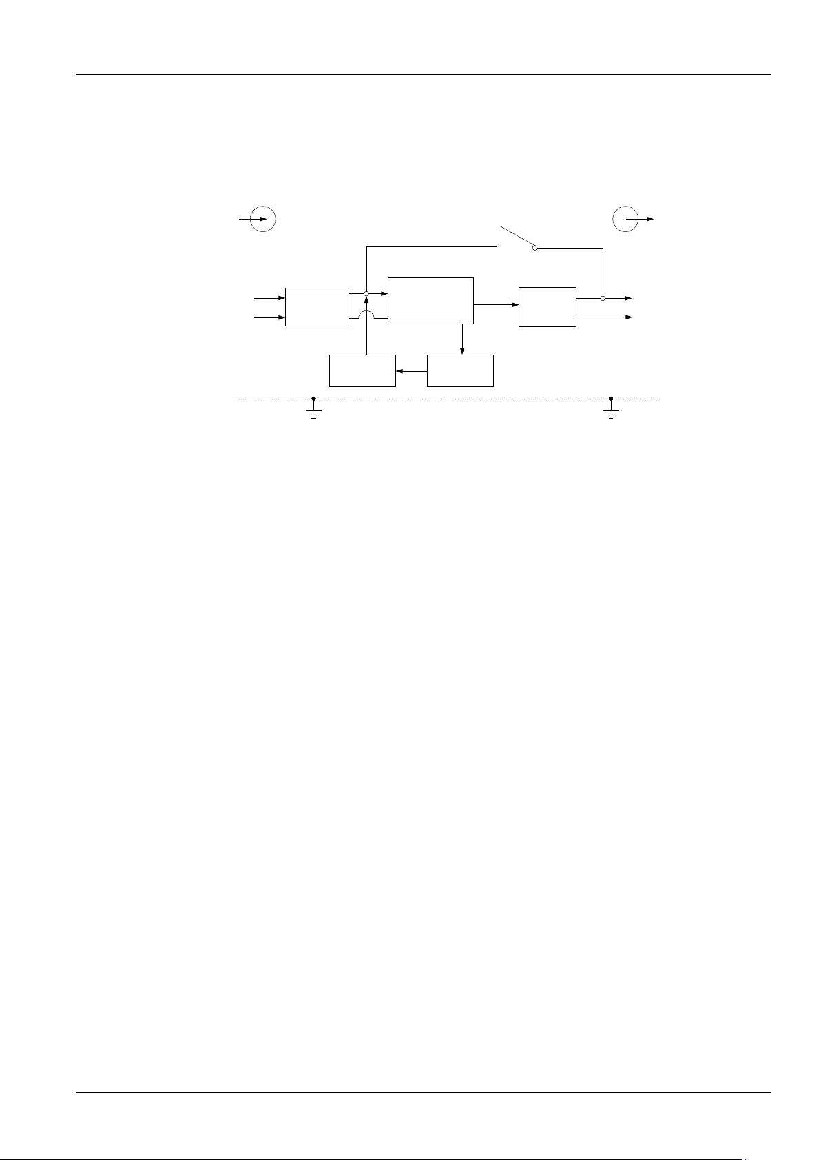
Chapter 2 System Description
The operating principle of the UPS is shown in Figure 2-1.
igure 2-1 Operating principle diagram
F
2.1 Transient Voltage Surge Suppression (TVSS) and EMI/RFI Filters
Thes e UPS c omp onents provide sur ge protection and fi l ter both elect romagnet ic i nterference (EMI ) and ra dio
frequency interference (RFI). They minimize any surges or interference present in the utility line and keep the
sensitive equi pment protected.
2.2 Rectifier/Power Factor Correction (PFC) Circuit
In normal operation, the rectifier/power fac tor c orrection (P FC) circuit conver t s uti lity AC power to regula ted D C power
for use by the inverter while ensuring that the waveshape of the input current used by the UPS is near ideal.
Extracting this sinewave input current achieves two objectives:
The utility power is used as efficiently as possible by the UPS.
The amount of distortion reflected on t he uti lity is r educed.
This results in cleaner power being available to other devices in the building not being protected by the Liebert
GXT4™.
2.3 Inverter
In normal operation, the inverter utilizes th e D C out put of the po wer fact or cor rection c i rcuit and inverts it into precise,
regula ted sinew ave AC po wer. Upon a utility power failur e, the i nver ter r eceives its required en ergy f rom t he battery
through the DC-to-DC converter. I n both modes of oper at ion, the U PS in verter is on-line and continuously generating
clean, precise, regulated AC output power.
®
2.4 Battery Charger
The battery charger utilizes energy from the utility power and precisely regulates it to continuously float charge the
batteries. The b atter ies are b eing charged whenever the Liebert GXT 4 is connected t o mains power.
2.5 DC-to-DC Converter
The DC-to-DC con verter utilizes en ergy from the b attery system and r aises the DC voltage to th e optimum operating
voltage for t he inverter. This allows t he inverter to oper ate con tin uously at its optimum efficiency and voltage, thus
inc reas ing reli abil ity.
Liebert GXT4 UPS 5000VA ~ 10000VA (230V) User Manual
Page 11

2.6 Battery
The L iebert® GXT4™ utilizes valve-regul ated, nonspil lable, lead acid b att er ies. To maintai n battery design life,
operate the UPS in an ambient temperature of 15°C to 25°C (59°F to 77°F). Optional extern al ba ttery cabinet s are
ava ila ble t o extend battery run times. For run ti mes, see Table 11-5.
2.7 Dynamic Bypass
The Liebert GXT4 provides an alternate path for utility power to the connected load in the unlikely event of a UPS
malfunction. Should the UPS have an overload, overtemperature or any other UPS failure condition, the UPS
automatically transfers the connected load to bypass.
NOTE
The bypass power path does NOT protect the connected equipment from disturbances in the mains supply.
Chapter 2 System Description 3
Liebert GXT4 UPS 5000VA ~ 10000VA (230V) User Manual
Page 12
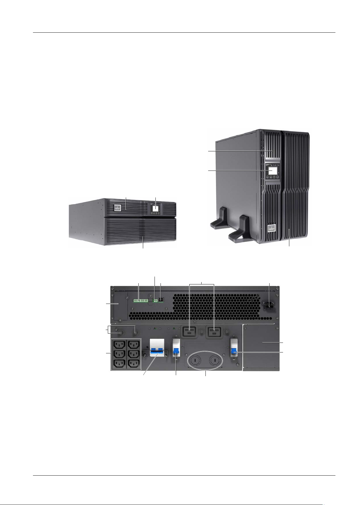
4 Chapter 3 Major Components
Operation and
display panel
Upper Bezel
Lower bezel and battery access door
Operation and display panel
Upper Bezel
Lower bezel and battery access door
Note: 10,000VA model's front layout is identical ;
the battery compartm ent is larger.
USB port
External battery connector
REPO connection block
Terminal block communication
Liebert IntelliSlot port
Output circuit
breaker
C19 output power
receptacles
Input circuit breaker
Maintenance
bypass breaker
IT power system
access cover
Knockouts for
hardwired power input
C13 output
receptacles
Output circuit
breakers
Chapter 3 Major Components
The L iebert® GXT4™ is composed of three major assemblies to provide easier handling, installation and ver sati l it y.
3.1 Main Frame and Electronics
The cabinet is shipped with internal batteries installed and a basic, hardwire distribution box attached and ready to
install.
Figu re 3-1 Liebert GXT4 5000VA and 6000VA (front view)
Liebert GXT4 5000VA and 6000VA
Liebert GXT4 UPS 5000VA ~ 10000VA (230V) User Manual
Page 13
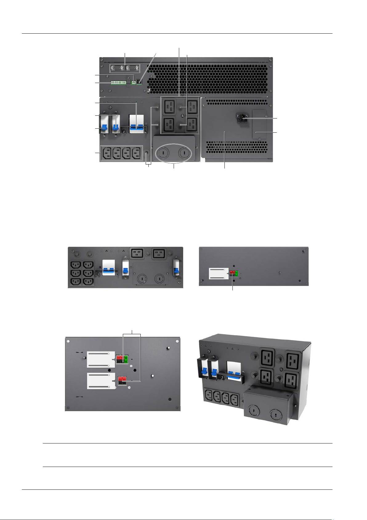
USB port
REPO
Terminal block
communication
Output circuit
breaker
C19 output power receptacles
External battery
connector
Maintenance
bypass breaker
Liebert IntelliSlot
port
Knockouts for
hardwired power input
C13 output
receptacles
Output circuit
breaker
Input circuit
breaker
Reserved
Output circuit breaker
IT power system
access cover
Liebert GXT4 10,000VA
Outer surface view of power distribution box
for 5000VA and 6000VA models
PD2-CE6HDWRMBS
Quick-connect
Inner surface view of power distribution box
for 10000VA model (PD2-CE10HDWRMBS)
Quick-connect
Front view
Figu re 3-2 Liebert® GXT4™ (rear view)
Chapter 3 Major Components 5
3.2 Removable Power Distribution Box
The UPS is shipped with a power distr ibut ion pa ck instal led, as sh own in Figure 3-3 and Figure 3-4. This box contains
the UPS input circ uit breaker.
Figu re 3-3 Power distribution box for GXT4 5000VA and 6000VA models
Note
Hardwire and hardwire/receptacle boxes that include a manual bypass switch allow AC power to continue to flow from the mains
input to the load while the box is removed from the UPS. For de tails , refer to 5.3 Connect Input/Outpu t Power.
Figu re 3-4 Power distribution box for GXT4 10,00 0VA mode l
Liebert GXT4 UPS 5000VA ~ 10000VA (230V) User Manual
Page 14
6 Chapter 3 Major Components
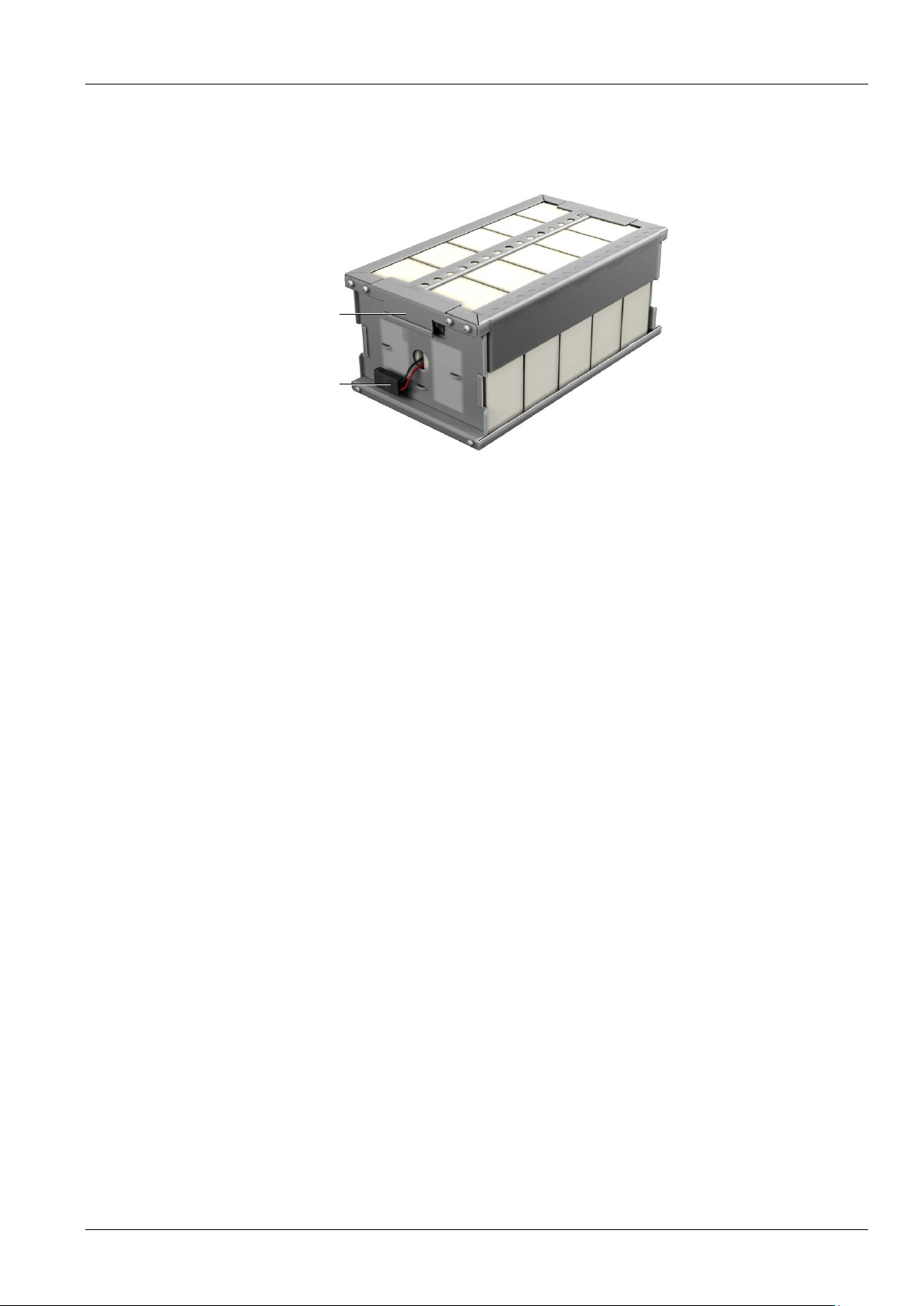
Battery handle
Battery connector
Front of battery pack
3.3 Internal Battery Packs
The UPS has two internal battery packs behind a battery access door on the front of the unit. Each intern al battery
pack is fitted with a connector to link to the UPS.
Figu re 3-5 Internal battery pack features
Liebert GXT4 UPS 5000VA ~ 10000VA (230V) User Manual
Page 15

Chapter 4 What’s Included 7
Chapter 4 What’s Included
The L iebert® GXT4™ is shipped with the following items:
Terminal Block Communication terminals
Compact disc with:
Lieb ert M ultiLin k®
Configuration program & Multi-languages package
User manual (electronic version)
USB cable, one; 2m (6-1/2 ft.) long
Mounting hardware, including screws and handles
Rack sli de kits (E models do not include)
Power Distribution Box , installe d on Liebert GXT4
Support base set, one
Warnings, safety instructions booklet and WEEE recycling sheet (ISO 14001 compliance)
Note
The Liebert GXT4 Exte rn al Battery Cabinet shipping package includes one battery cabinet, two spa cers for towe r configur ation
and one DC power cable.
Liebert GXT4 UPS 5000VA ~ 10000VA (230V) User Manual
Page 16

8 Chapter 5 Installation and Configuration
Support bases
Connector
Spacer
Chapter 5 Installation and Configuration
Do NOT att empt t o star t t he UPS , tur n on any cir cuit break er or ener gize the input pow er until instructed to do so in
8.2 Initial Sta rtup And Electrical Checks.
Visually inspect the UPS for shipping damage. Report any damage to the carrier and your local dealer or Emerson
representative.
Caution
The UPS is heavy (ref er to Chapter 11 Specifications). Take proper precautions when lifting or movin g it.
nstall the Liebert® GXT4™ indoors in a controlled environment, where it cannot be accidentally turned off. Place it
I
where air flows unrestricted around the unit. The insta llation l ocat ion must be free of w ater, flammable l iquids, gases,
corrosives and conductive contaminants. Maintain a minimum clearance of 100mm (4 inches) in the front and rear of
the UPS. M ain tain a n ambient t emperat ure range of 0 to 40°C (32°F ~104°F).
Note
UPS operation in sustained temperatures outside the range of 15°C ~ 25°C (59°F ~ 77°F) reduces b atter y l ife.
5.1 Install Main Cabinet
The Liebert GXT4 may be installed in either a tower configuration or in a rack, depending on available space and us e
considerations. Determine the type of installation and follow the appropriate instructions in either 5.1.1 Tower UPS
Installation or 5.1.2 Rack-Mount UPS Installation.
5.1.1 Tower UPS Installation
T o install the Liebert GXT4 as a tower:
1. Take the support bases out of the accessories bag (see Figure 5-1).
2. If optional Liebert external battery cabinets will be connected to the Liebert GXT4, take out the spacers shipp ed
with the battery cabi net.
3. Connect the spacers and the support bases as shown in Figure 5-1. Each L iebert G XT4 needs tw o assemble
support bases, one in the front and one in the rear.
4. Adjust the direction of the operation and display panel and logo on the Liebert GXT4.
1) Remov e the f ront pla s t ic bezel cover as sh own i n Figure 5-2.
igure 5-1 Su pp or t bases
F
d
Liebert GXT4 UPS 5000VA ~ 10000VA (230V) User Manual
Page 17

Chapter 5 Installation and Configuration 9
Front plastic
bezel cover
Operation and
display panel rotated
clockwise 90 degrees
Figu re 5-2 Remove the front plastic bezel cover
2) Pull the operation and display panel gently, rot ate it 90 degrees c lockwi se and snap i t back into position, as shown
in Figure 5-3.
Figu re 5-3 Rotate the operation and displ ay panel
3) Pull the logo on the front plastic bezel cover gently, rotate it 90 degrees clockwise and snap it back into position.
The rotated front plastic bezel cover is shown in Figure 5-3.
4) Replace the front plastic bezel cov er on th e Liebert® GXT4™. At this point, the UPS operation and display panel
and logo have been rotated 90 degrees clockwise, which provides upright viewing for users.
5. Place the Liebert GXT4 and any battery cabinets on the support bases. Each Liebert GXT4 needs two support
assemblies, as shown Figure 3-1.
5.1.2 Rack-Mount UPS Installation
When usi ng th e Liebert G XT4 in a rack, the UPS must be supported by a slide kit, fixed r ails or a shelf.
When using the Adjustable Rack Mount Kit, you will use the following instructions. The figures accompanying 5.1.3
Installing Adjustable Rack-Mount Kit—Sold Separately shows the positioning of the rack-mounti ng bra ckets. Emerson
recommends taki ng the interna l batt eries out of t he UPS d uring rac k install atio n. This w ill m ake the UPS cabinet
lighter and easier to handle.
Caution
The Liebert GXT4 i s heavy; refer t o Chapter 12 Specifications. The UPS must be in stalled as near the bott om of a rack as
possible. If placed too high, it can make the rack top-heavy and prone to tipping over.
5.1.3 Installing Adjustable Rack-Mount Kit—Sold Separately
This kit contains parts needed to mount several different models of UPS and external battery cabi nets into EIA310-D
standard four-post racks that are 18" ~ 32" deep (457mm ~ 813mm). The weight limit per pa ir of adju stable
rack-mounting brackets is 91kg (200lb ). Par ts inc luded are shown in Table 5-1.
Liebert GXT4 UPS 5000VA ~ 10000VA (230V) User Manual
Page 18

10 Chapter 5 Installation and Configuration
Item
Quantity
Rear brac k et m em bers
2
Front bracket members
2
Inner br ac k et m emb er s
2
M4 machine screws
16
M4 locking hex nuts
8
M5 machine screws
8
Inner member
Front member
Pull out
Retaining latch
Rear member
M5 screw (4 pcs)
Mounting rail
Rear member
Front member
Tabl e 5-1 Included parts in rack-mount kit
Tools needed for installation are:
one Phillips screwdriver
one 7mm wren ch
The adjustable rack-mounting brackets (P art# : R MKIT18-32) feature retaining latches to prevent users from
inadvertently sliding the UPS or battery cabinet out of the rack.
T o install the rack mount brackets:
1. Unpack two rack-mou nt ing b racket as semblies and mounting hardware from this kit. Bracket assembl ies are
interchan geable between left-hand or right-hand.
2. Remove inner member of each bracket assembly shown in Figure 5-4 by extending it to its outermost position,
depressing the retaining latch and then pul ling the inner me m be r out of the bracket as sembly.
Figu re 5-4 Removing inn er me m ber of e ac h br ac k et ass e mb ly
3. Determine the height position inside the rack enclosure where you want to mount the UPS or battery cabinet.
Caution
Reduce the risk of tipping the rack enclosure by placing the UPS or battery cabinet in the lowest possible rack p osition.
4. Ins ta ll the rea r member of each b rack et assembly into the rack enclosure with two M5 screws provided in this kit
(see figure at right). The return flanges on the bracket assem bly fit to the inside of rack mounting rails. Insert screws
loosely (finger-tight) into the top and bottom holes of the return flange on the rear member.
Figu re 5-5 Installing rear member of each bracket assembly
5. Extend the bracket assembly by sliding the front member forward unt il it touches the front rack mounting rail. Insert
two M5 screws loosely ( finger-ti ght) into the top and bottom holes of the return flange on each front member. Make
sure that the bracket as sembl ies are at the s ame mounting height on all four (4) rack mounting rails.
Liebert GXT4 UPS 5000VA ~ 10000VA (230V) User Manual
Page 19

Chapter 5 Installation and Configuration 11
Front vertical pole
M5 screw (4 pcs)
Front member
Rear member
Slide
M4 screw (8 pcs)
Rear member
Front member
M4 nut (8 pcs)
+-
Liebe
rt
.GXT3
AC Power
3000VA
!
1
2
M4 screw (8 pcs)
Retaining latch
Inner member
UPS
Figu re 5-6 Installing front member of eac h brac ket assem b ly
6. Get eight M4 screws and eight M4 nu ts from the hard w are pack in this kit. Each nut has a locking, nylon insert that
begins gripping the screw when it is halfway tight. Make sure to tighten the n ut and screw completely to ensu re
locking action. Fasten the rear member and the front member together using four screws and four nuts per bracket
assembly as shown in Figure 5-6. For maxi mum support, insert fasteners for each bracket assembly as far apart as
possible, depending on rack depth, while still joinin g both memb ers (see figures at right). C heck ali gnm ent of brack et
assemblies and TIGHTEN ALL SCREWS FROM Step 3 to Step 5 .
7. Prepare the UP S or ba t tery cab i net (the ‘equipment’) for rack mounting by following instructions in the equipment’s
user manual. The equipment may require additional parts to be added or parts to be removed for rack mounting. After
it i s prepa red, lay the equipment in rack-mounting position. Fasten the inner members from Step 2 to the equipment
on both sides as shown at right with eight M4 screws provided in the kit. Make sure retaining latch is near the rear of
the equipment as shown (see fig ure at right).
8. If available, apply a bead of grease 1" (25mm) long at four places inside the bottom, curved tracks of the front
members as shown below right. The grease will allow the equipment to slide into the bracket assemblies more easily.
Figu re 5-7 Fastening the rear member and the front member to ge t h er
Figu re 5-8 Fastening the inner members to the equipment
Liebert GXT4 UPS 5000VA ~ 10000VA (230V) User Manual
Page 20

12 Chapter 5 Installation and Configuration
Inner member
Front member
Insert
Caution
1. Lifting equipment into the rack may be a two-person job, depending on the weight of the equipment.
2. Liebert® recomm e n d s taking th e inter n al batte r ies out of the UPS d uring rack i nstallation. This will make the UPS cabinet
light e r and eas ier to handle.
3. The Li ebert GXT4™ weighs 151 lb. (67kg). For the UPS weight, see Table 11-1; for the bat tery cabinet ’s weight, s ee Tabl e
11-5.
4. Factory-supplied rack handles are not intended to be used to lif t the UPS. The handles are intended to be used to slide the UPS
into and ou t of the rack.
9. In sert the equipment , with inner members attached in Step 7, into the bracket assem blies by inserting the top and
bottom edges of the inner members into the top and bottom curved tracks of the front members and sliding the
equipm ent i nto the rack (see Figure 5-9). Ends of inner members are tapered to allow the rear of the equipment to be
angled upward before insertion, if space allo w s .
Then the rear, bottom edges of the inner members can be placed into the front edge of the bottom tracks and the
fr ont of the equipment can be tip ped up so they are level to insert the top ed ges of the inner members before sliding
the equipment into the rack (see Figure 5-9). The equipment should move smoothly into the bracket assemblies. If it
does not, recheck the alignment of t he front an d rear members from Steps 4 and 5.
Figu re 5-9 Inserting the UPS
10. Secure the front of the equi pment to the rack mou nt ing rail s to prevent the equipm ent from sliding out of position.
If securing holes are provided on the front of the equipment that al ign w i th the center holes on the return flange of the
fr ont members, you can use the fo ur extra M5 screw s provided in the ki t to secur e t he equipment. O therwis e, th e
equipm ent shoul d be sec ured to the front of the rack wi th four customer-supplied fasteners.
5.2 External Battery Cabinet Installation
Optional Liebert® external battery cabinets may be connected to the UPS to provide additional battery run time.
External battery cabinets are designed to be placed on one side of the UPS or stacked beneath the UPS. External
battery cab inets can b e used in either a rack-mount or tower configuration.
Caution
The external battery cabinet(s) are heavy (refe r to Chapter 12 Specifications). Take proper precautions w hen lif ting them.
Liebert GXT4 UPS 5000VA ~ 10000VA (230V) User Manual
Page 21

Chapter 5 Installation and Configuration 13
10,000VA
Liebert GXT4
Cables connecting
battery cabinets to
10,000VA
Liebert GXT4
Battery cabinet
Figu re 5-10 External battery cabinets connected to 10,000VA Liebert® GXT4™
1. Inspect the external battery cabinet for freight damage. Report damage to the carrier and your local dealer or
Emerso n represent ative.
2. For slide rail installations, first remove the top/side fin. Top/si de fin slides forward and then lift up to re move.
Optional rack-mount handles are shipped with the external battery cabinet and may be installed at this time if desired.
3. Securing hardware and slide rails are sold separately. Please contact your local dealer or Emerso n representat ive
for these additional options and any assistance needed. Fasten the slides in t o pos i tio n w ith the sc rews per the
instructions included with the slide rails.
4. Use the enclosed support bases for the tower option to prevent tip-over. One a ddit ion al set of support base
extensions ships with each external battery cabine t.
5. Put the UPS in Bypass Mode by operating LCD configuration
6. Verify the External Battery Cabinet breaker is in the Off position.
7. Connect the suppli ed externa l battery ca binet cable to the rear of the external battery cabinet, then to the rear of
the UPS.
8. Turn the Exte rnal Battery Cabinet breake r to the On position.
9. Operating LCD panel to return the unit to Inverter Mode.
10. Verify the circuit breake r on the Exte rnal Battery Cabinet is in the On position.
11. Use the included configuration program or LCD to progr am the U PS for the n umber of extern al battery cabinets
connected. Instructions for the configuration program are in 6.0 Configuration Program.
12. The UPS is now equipped with additional backup battery r un time. For ap proxi mate bat tery run times, refer to
Table 11-5.
Note
1. When re m oving th e Exter n al B attery Cabi net, the ci rcui t breaker on th e rear of th e cabinet mu st be turned off be f ore
disconnectin g the cable.
2. If th e UPS is to be shipped or stored for an e xtend ed tim e, the con nector sh ould be disc onnecte d. Thi s will min imize any
standby current drain on the batteries and help attain their de sign life.
Liebert GXT4 UPS 5000VA ~ 10000VA (230V) User Manual
Page 22

14 Chapter 5 Installation and Configuration
Maintenance bypass breaker
Extract these captive sc rews
Extract these captive sc rews
Maintenance bypass breaker
Power distribution box removal from
5000VA and 6000VA models
Power distribution box removal from 10, 000V A model
5.3 Connect Input/Output Power
Figu re 5-11 Power Distribution box removal—captive screws and maintenance bypass breaker
The UPS should arrive with the power distribution box attached. If the box needs to be removed for maintenance or
replacement, follow these instructions to remove and install the power distribution pack.
To r emove:
1. Ensure mainten ance bypass lam p is on. To place th e unit in m aintena nce bypas s, refer to 8.4 Put Liebert GXT4
In Bypass.
2. Loosen one captive screw over the maintenance bypass breaker.
3. Turn the maintenance bypass breaker on.
Notice
The l oad is un prot ected f rom disturbances in the power supply while the UPS is on bypass.
4. Turn the output and input breaker off.
5. Loosen other captive screws until the power distribution box releases.
6. Remove the power distribution box from the UPS and set it aside.
7. Loosen scre ws over the plastic cove r for the connector on the rear of the panel.
8. Slide plastic cover over connector and tighten screws.
Note
Do not operate the UPS with this box removed. To disconnect all power to this box and load, the utility input power also must be
disconnected.
To install:
1. Align connectors and press box onto UPS
2. Hold box firmly against UPS and tighten captive screws except one over the maintenance bypass breaker.
3. Turn the output and input breaker on.
4. Start the UPS according to startup instructions.
5. Verify that the UPS lamp is illuminated.
6. Turn the maintenance bypass breaker off.
7. Insert the maintenance bypass cover behind the captive screw and tighten the screw.
Note
The maintenance bypass breaker cover must be installed behind the captive screw and the scr ew must be tighten ed for the UPS to
operate in inverter mode.
Liebert GXT4 UPS 5000VA ~ 10000VA (230V) User Manual
Page 23

Chapter 5 Installation and Configuration 15
Unit Rating
Maximum Breaker Rating
5000VA
6000VA
Recommended
Recommended Wire
Maximum Wire
Terminal
GXT4-5000RT230
GXT4-10000RT230
PD2-CE10HDWRMBSPD2-CE6HDWRMBS
Distribution box electrical connections
Electrical connections are made through a removable power distribution box that attaches to the rear of the UPS.
PD2-CE6HDWRMBS fits the 5000 and 6000VA models of the Liebert GXT4
PD2-CE10HDWRMBS fits the 10,00 0VA model of the Liebert GXT4
The installer mus t provid e an ups t ream bran ch circui t breaker. The inp ut circuit breaker on the distri bution box and
the output circuit breaker on the rear of the power distribution box disconnect all power between the main cabinet and
the distribution box.
Models equipped with a manual bypass breaker pass bypass power directly to the bypass breaker from the input
terminal block . The inp ut circuit breaker on the distribution box does not disconnect power from the manual bypass
breaker.
Tabl e 5-2 Branch circuit breaker ratings
D Type 32A
10,000VA D Type 63A
Figu re 5-12 Distr ibution box e lec trical connecti ons d iagr am
Terminal block connections—PD2-CE6HDWRMBS and PD2-CE10HDWRMBS
Conduit entry holes are provided on the rear and side of the box. Input and output wiring should not share the same
con duit . Emerso n recommen ds using strain relief w hen installing th e wire.
Tabl e 5-3 Electrical specifications
UPS Mod el
GXT4-5000RT230E
GXT4-6000RT230
GXT4-6000RT230E
GXT4-10000RT230E
(Maximum) External
Overcurrent Protection
32A 4mm2 (10AWG) 6mm2 (8AWG)
63A 10mm2 (6AWG) 16mm2 (4AWG)
(Including ground wire)
(75°C copper wire)
Accept ed b y
Term inal Block
Tightening
Torque
2.26Nm (20 in-lb)
Figu re 5-13 Terminal block connections—PD2-CE6HDWRMBS and PD2-CE10HDWRMBS
Liebert GXT4 UPS 5000VA ~ 10000VA (230V) User Manual
Page 24

16 Chapter 5 Installation and Configuration
Note
1. The installer must provide c ircuit breaker protection accordin g to local cod es. The ut ili ty disconnect should be within sight of
the UPS or have approp r iate a n ap propr iate l ock-out. Maintain service s pace around the UPS or use flexible con duit .
2. The installer must provide outpu t distr ibut ion pa nels, ci rcuit bre aker prote ction or emergency dis connec ts accordi ng to local
codes . Outp ut circuits mu st not sh are a common conduit with any other wiring.
Liebert GXT4 UPS 5000VA ~ 10000VA (230V) User Manual
Page 25

Chapter 6 Configuration Program
The final step of installation may require custom configuration of your UPS using the enclosed configuration program.
Some configuration settings may be changed only while the UPS is off. These should be set before the UPS is put
into full-time ser vice powerin g the cr itical load .
For most users operating with 230VAC and with no external ba tt er ies, the factory defa ult s etti ngs will be adequate.
6.1 Configuration Program Features
Select L-N output voltages to match local voltages.
Enable/Disable Auto-Restart.
Select f requ ency conv erter oper ati on with a fixed output fr equency of 50 or 60 Hz.
Set t he Low B attery War ning alarm time from 2 to 30 minutes.
Enable/Disable the Auto-Battery test.
Set the Auto-Battery test to 8, 12, 16, 20 or 26 weeks.
Specify the number of external battery cabinets connected to the UPS to adjust the remaining run time
calculations reported by Liebert® software products.
Modify the shutdown se tting of the terminal block (for infor mation on pin assign ments, see Table 5-3).
Chapter 6 Configuration Program 17
6.2 What You Will Need
In addition to the Liebert GXT4™ UPS, you will need the configuration program CD and USB cable included in the
UPS accessory box. A Windows 95® or later computer, desktop or laptop, is also required to set up and run the
configuration program.
Liebert GXT4 UPS 5000VA ~ 10000VA (230V) User Manual
Page 26

18 Chapter 7 Operation And Display Panel
ESC button
UP button
Bypass indicator
DOWN button
Green mode indicator
LCD display panel
Battery indicator
Fault indicator
Inverter indicator
ENTER button
LED Indicators
LED color
Description
Inverter in dicator
Green
On when the inverter is supplying power, and off otherwise
On when th e l oad is supplied by the mains through automatic/manual
Battery indicator
Amber
On when th e l oad is suppli ed by the batt ery, and off otherwise
Fault indicator
Red
On when an error has occurred within the UPS, and off ot h erwise
Green mod e in dicator
Green
On when the UPS is in green mode, and off otherwis e
Control buttons
Description
Pressing this button returns to the previous menu or aborts any change in the input data field
Pressin g t his but ton can move th e cu r sor up or incr ease the valu e display ed in th e in put data
Pressing this button can m ove t h e cu rsor down or decreas e th e val u e display ed in t h e in put
ENTER button
Pressing this button can enter the next level menu or confirm the paramet er s etting value
Chapter 7 Operation And Display Panel
This chapter describes the operation and display pa nel of the Liebert GXT4, including LED indicators, control buttons
and LCD display panel.
The operation and display panel is on the front panel of the Liebert GXT4 (see Figure 7-1), which provides four
control buttons, seven LED in dicators and a LCD display panel , as shown in Fig ure 7-1.
7.1 LED Indicators
The operation and display panel provides seven LED i ndicators: inverter indicator, bypass indicator, battery indicator,
fault indicator, and green mode indicator. Their desc r iptions are list ed in Table 7-1.
Bypass indicator Amber
Caution
Do not swit ch off the UP S or swi tch fr om online to b ypass , otherwise the loads will no longer be supported.
7.2 Control Buttons
The operation and display panel provides four control buttons: ESC button, UP button, DOWN button and ENTER
button. Their d escriptions are list ed in Table 7-2.
Figu re 7-1 Operation and display panel
Tabl e 7-2 LED indicators
by pas s, a nd off other wise
ESC button
UP button
DOWN button
Liebert GXT4 UPS 5000VA ~ 10000VA (230V) User Manual
before confirming
field. When a menu is displayed on several screens, pressing the button can scroll up
data field. When a menu is displayed on several screens, pressing the button can scroll down
Tabl e 7-3 C on t ro l buttons
Page 27

7.3 LCD Display Panel
O / P : 230V 50HZ 17.6A
I / P : 230V 50HZ 18.0A
BATT
: 100% 100MINS
LOAD : 80%
TURN ON UPS
YES NO
O / P : 230V 50HZ 17.6A
I / P : 230V 50HZ 18.0A
BATT
: 100% 100MINS
LOAD : 80%
AC N OT AVAILABLE
START ON BATTERY?
YES NO
O / P : 230V 50HZ 17.6A
I / P : 230V 50HZ 18.0A
BATT
: 100% 100MINS
LOAD : 80%
START SUCCESSFUL
O / P : 230V 50HZ 17.6A
I / P : 230V 50HZ 18.0A
BATT
: 100% 100MINS
LOAD : 80%
GXT4 - UPS 6KVA
The operation and display panel provides a LCD display panel, enabling you to view the UPS status and change the
UPS settings.
7.3.1 Startup Screen
When the UPS is starting up, the UPS begins self-testing, and then the LCD display panel will displ ay EMERSON
icon for about 10s, as shown in Figure 7-2.
7.3.2 ON Screen
About 10s later, the LCD display panel will display the corresponding ON screen depending on whether the AC is
available, as shown in Figure 7-3.
Chapter 7 Operation And Display Panel 19
Figu re 7-2 Startup screen
Select ‘YES’ and press the ENTER button, the UPS will start up, and the LCD display panel will display ‘START
SUCCESSFUL’, as shown in Figure 7-4.
7.3.3 Default Screen
Press any button in the ‘STATTUP SUCCESSFULLY’ screen to enter the default interface, as shown in Figure 7-5.
Figu re 7-3 Startup screen
Figu re 7-4 ‘START SUCCESSFUL’ screen
Figu re 7-5 Default screen
In the default screen, the LCD display panel will display the UPS model, operation mode (ONLINE, GREEN, GREEN
AUTO , and BY PASS ) , output parameters, i nput parameters, batt ery capacity and load percentage.
If n o control button is pres sed wi thi n two minutes, the LCD dis play panel wil l ent er a screen-protection state (the back
lighting is off) until any control button is pressed .
Liebert GXT4 UPS 5000VA ~ 10000VA (230V) User Manual
Page 28

20 Chapter 7 Operation And Display Panel
1 STATUS
2 CONFIGURATION
3 CONTROL
4 LOG
5 ABOUT
VOLT : 230V
FREQ
: 50Hz
CURR
: 17.6A
POWER : 4000WH
OUTPUT
CAP : 90%
WATT
: 4000W
VA : 4000VA
LOAD
VOLT : 230V
FREQ
: 50HZ
CURR : 18.6A
POWER: 4000WH
INPUT
VOLT : 230V
FREQ
: 50HZ
CURR : 17.6A
PARALLEL
CAP : 90%
WATT
: 4000W
VA : 4000VA
PARALLEL
CAPACITY : 90%
RUNTIME : 100M INS
VOLTAGE : 148V
BATTERY
TIME SINCE STARTUP
05D 15H 30M
1 UPS
2 BATTERY
3 ECO
4 LCD
5 FACTORY DEFAULT
7.3.4 Main Menu Screen
Press any button in the d efaul t screen t o enter the Main Menu screen, a s shown in Figur e 7-6.
To s elect a submenu, press th e UP or DOWN button t o m ove the cur sor to the required item, and press the ENTER
button to ent er its submenu o r set its paramet er.
STATUS screen
Select Main M enu -> 1 STATUS to enter the STATUS screen, displaying OUTPUT, LOAD, INPUT,PARALLEL,
BATTERY and TIME SINCE STARTUP, as shown in Figure 7-7.
Figu re 7-6 Main Menu screen
Figu re 7-7 STATUS screen
CONFIGURATIO N screen
Select M ain M enu -> 2 CONFIGURATION to enter the CONFIGURATION scree n. This menu has five submenus , as
shown in Figur e 7-8.
Figu re 7-8 CONFIGURATION screen
In the CONFIGURATION screen, press the UP or DOWN button to move the cursor to the required it em , and press
the ENTE R but t on to en ter its submenu or set its parameter.
1. UPS screen
Select M ain M enu -> 2 CONFIGURATION -> 1 UPS to enter the UPS scr een. This menu has seve n screens, as
shown in Figur e 7-9.
Liebert GXT4 UPS 5000VA ~ 10000VA (230V) User Manual
Page 29

Chapter 7 Operation And Display Panel 21
AUDIBLE ALARM
ON OFF
STARTUP ON BYPASS
YES NO
ENABLE AUTO RESTART
YES NO
GUARANTEE SHUTDOWN
YES
NO
FREQUENCY SELECTION
AUTO - BYPASS ENABLE
AUTO - BYPASS DISABLE
VOLTAGE SELECTION
230
PARALLEL
TYPE 3
ADDRESS 3
EXT BATT CABINET
0 CABINETS
LOW BATTERY TIME
0 2 CABINETS
BATT TEST INTERV AL
2 6 WEEKS
BATT REPLACE TIME
2 0 13 Y 0 8 M 0 8 D
OPERATION MODE
ONLINE MODE
GREEN MODE ON
GREEN MODE AUTO
1 LANGUAGE
2 COLOR
Figu re 7-9 UPS screen
Press the UP or DOWN button to move the cursor to the required item, and press the ENTER button to c onfi r m the
settings.
2. BATTERY scr een
Select Main M enu -> 2 CONFIGURATION -> 2 BATTERY to e nte r the BATTERY scree n. Th is menu has four
submenus, as shown in Fig ure 7-10.
Figu re 7-10 BATTERY screen
Press the UP or DOWN button to increase or decrease the value of the settings, and press the ENTER but ton to
confirm it.
3. OPERATION MODE screen
Select M ain M enu -> 2 CONFIGURATION -> 3 OPERA TI ON M ODE to enter the OPERATION MODE screen, as
shown in Figur e 7-11.
Figu re 7-11 OPERATION MODE screen
Press the UP or DOWN button to move the cursor to the required item, and press the ENTER bu t ton to con f irm the
settings.
4. LCD screen
Select M ain M enu -> 2 CONFIGURATION -> 6 LCD to enter the LCD screen. This menu has tw o submenus , as
shown in Figur e 7-12.
1) Selec t ‘1 LANGUAGE’ and press the EN TER bu t ton to enter th e LANGUAG E screen , as show n i n Figure 7 -13.
Figu re 7-12 LCD screen
Liebert GXT4 UPS 5000VA ~ 10000VA (230V) User Manual
Page 30

22 Chapter 7 Operation And Display Panel
1 ENGLISH
2
中文
3 Upload others
EMERSON
EMERSON
EMERSON
EMERSON
RESET ALL SETTINGS
TO FACTORY DEFAULT
SETTINGS?
YES NO
1 TURN ON & OFF
2 ALARM CONTROL
3 BATT TEST
TURN UPS ON
TURN UPS OFF
TURN UPS BYPASS
2) Selec t ‘2 COLOR’ and press the ENTER button to enter the COLOR screen, as shown in Figure 7-14.
5. FACTORY DEFA ULT screen
Select M ain M enu -> 2 CONFIGURATION -> 7 FACTORY DEFAU LT to enter the FACTORY DEFAULT screen, a s
shown in Figur e 7-15.
Figu re 7-13 LANGUAGE screen
Figu re 7-14 COLOR screen
Figu re 7-15 FACTORY DEFAULT screen
CONTROL Screen
Select M ain M enu -> 3 CONTROL t o ent er the CONTROL screen, as shown in Figure 7-16.
Figu re 7-16 CONTROL screen
In the CONTRO L screen, press t he UP or DO WN button to move the cur sor to the requ ired i tem, and press the
ENTER button to enter its submenu.
1. TURN ON & OFF screen
Select M ain M enu -> 3 CONTROL -> 1 TURN ON & OFF to enter the TURN ON & OFF screen, as shown in
Figure 7-17.
2. ALARM CONTROL screen
The UPS is off The UPS is on
Figu re 7-17 TURN ON & OFF screen
Liebert GXT4 UPS 5000VA ~ 10000VA (230V) User Manual
Page 31

Chapter 7 Operation And Display Panel 23
1 AUDIBLE ALARM ON
2 AUDIBLE ALARM OFF
1 START
2 CANCEL
3 BATT TEST RESUL T
1 EVENT LOG
2 CLEAR LOG
254/255
255 OD 1H 17M AGO
UPS switch to Online
mode
DO YOU WANT TO
CLEAR EVENT LOGS?
YES NO
Select M ain M enu -> 3 CONTROL -> 2 ALARM CONTROL to enter the ALARM CONTROL screen , as shown in
Figure 7 -18.
Figu re 7-18 ALARM CONTROL screen
3. BATT TEST screen
Select M ain M enu -> 3 CONTROL -> 3 BATT TEST to enter the BATT TEST screen, as shown in Figure 7-19.
Figu re 7-19 BATT TEST screen
LOG Screen
Select M ain M enu -> 4 LOG to enter the LOG sc reen, as shown in Figur e 7-20.
Figu re 7-20 LOG screen
1. Selec t Main Menu -> 4 LOG -> 1 EVENT LOG to enter the EVENT LOG screen, as shown in Figure 7-21.
Figu re 7-21 ALL LOG screen
2. Selec t Main Menu -> 4 LOG -> 2 CL EAR LOG to enter the CLEAR LO G s creen, as shown in Figure 7-22.
Press the UP or DOWN button to move the cursor to the required item, and press the ENTER bu t ton to con f irm the
settings.
ABOUT Screen
Select Main M enu -> 5 ABOUT to enter the ABOUT screen, as shown in Figure 7-23.
Figu re 7-22 CLEAR LOG screen
Liebert GXT4 UPS 5000VA ~ 10000VA (230V) User Manual
Page 32

24 Chapter 7 Operation And Display Panel
The ABOUT screen displays: UPS model, SN, software version and hardware version.
Menu structure
The menu struc ture of the LCD display panel is shown in Figure 7-24.
Figu re 7-23 ABOUT screen
7.3.5 Prompt List
A prompt screen i s displayed during the operati on of the sy st em t o alert you to certain conditions and/ or to require
your confirmation of a command or other ope ration . The prompts and meanings are given in Table 7-3.
Figu re 7-24 Menu structure
Liebert GXT4 UPS 5000VA ~ 10000VA (230V) User Manual
Page 33

Chapter 7 Operation And Display Panel 25
No.
Prompt
Meanings
The utility power recovers, and the UPS transfers back to Utility (AC)
The bypass power recovers, and the UPS can transfers back to
3
UPS return from a low battery condition
The UPS transfers back to Utility (AC) mode from Battery low mode
4
UPS return from battery mode
The UPS transfers back to Utility (AC) mode from Battery mode
Conditions of battery test do not meet,UPS battery test is not
6
UPS self test successful
The UPS self-test is successful ly performed
7
UPS self test in progress
The UPS is performing self-test
8
UPS turn off
The UPS shuts d ow n an d has no output
9
UPS TURN ON
The UPS starts up successfully and supplies power to the load
10
UPS Maint en ance bypas s output
The UPS M ai ntenance bypass ou tput
11
UPS shutdown command received
The UPS shuts down through communication
The shutdown command sent through Multilink or SNMP card to the
13
UPS switch to Green mode
The UPS trans fers bac k to Gr een m ode, saving m ore electr icity
When the input utility power satisfies the condition of Auto Green
The UPS transfers back to Online mode, supplying power to the
16
UPS internal temperature return to normal
The internal temperature of the UPS recovers to normal range
The loads are reduced, and the UPS recovers to normal state from
The beeper is disabl ed, and no aud ib l e alarm will be g en er at ed
The beeper is enabl ed, an d au dible alar ms wi ll b e gen erated wh en
No.
Warning
Description
The utility power is not available, or it cannot satisfy the
2
UPS batteries low and exhausted soon
The batter y c apacity is low an d wi ll b e exh aus ted soon
The utility power is abnormal or the PFC side is faulty, the UPS
The UPS transfers back to Bypass mode, at this point, the input
The bypass power is not available, or it cannot satisfy the
Ground is not c on nected or L/N w ires are rev er sed or Input
Tabl e 7-4 Prompts and me anings
1 Utility power restored
2 Bypass power restored
5 UPS battery test unallowed
12 UPS shutdown process had been cancelled
14 UPS switch to Auto Green mode
15 UPS switch to Onl ine mode
17 UPS load return from ov er l o ad
18 Beeper Disable
mode
bypass
allowed
UPS is cancelled
mode, the UPS will transfer back to Auto Green m od e
load through the in ver ter
overload
when faul ts or w arnings occ ur ag ai n
19 Beeper Enable
7.3.6 Warning List
All UPS warning messages are described in Table 7-4.
1 Utility power not available
3 UPS has switched to battery mode
4 UPS Switch to Bypass
5 Bypass power not available
6 Input pow er w iring error
faults or w arnings occ ur ag ai n
Tabl e 7-5 Warning list
requir em en ts for the UPS to operate
tran sfers back to Battery mode
utility power supplies power to the load directly, and the load is
not protected
requirements for the UPS to transfers to bypass (include phase
angle abn ormal for tw o ph as e m od el)
phase error
Liebert GXT4 UPS 5000VA ~ 10000VA (230V) User Manual
Page 34

26 Chapter 7 Operation And Display Panel
No.
Fault
Description
1
UPS self test failed
The battery is bad or weak
2
PFC Out of Order
PFCfailure occurs
3
UPS overl oad
The UPS is ov erloaded
4
Inverter Out of Order
The inverter is faulty
5
Battery Weak/Bad
The battery is bad or weak
6
Output Sh or t-circuit
The output connection is short-circuited
7
DC Bus Over-voltage
The DC bus is faulty
Over-temperature occurs to the UPS and the UPS will transfer to
9
Charger Out of Order
The charger is faulty
10
Fan Out of Order
At least one fan is faulty
11
DC Bus Discharge Fail
DCDC failure occurs
7.3.7 Fault List
All UPS fault messages are described in Table 7-5.
Tabl e 7-6 Fa ult l ist
8 UPS Over-temperature
Bypass mode
If a fault occurs, t he UPS automatically switches to Bypass mode. Only in the case of a battery disconnection fault will
the original operating mode be maintained. The fault message alternates with UPS mode once a second, the red fault
indicator on the operation and display pane l lights up and the alarm sou nds continuous ly.
If a fault occurs, proceed as follows:
1. Enter the ALARM CONTROL screen ( see Fi gur e 7-18), and select ‘AUDIABLE ALARM ON’ or ‘AUDIBLE ALARM
OFF’ to switch on/off the alarm.
2. Enter the EVENT LOG screen (see Figure 7-2 1), and select ‘3 CRITICAL’ to view the fault log.
Note
Please wait patiently when you enter the EVENT LOG screen to view the historical fault log. Because the LCD display panel
needs to read the faults from the DSP at a relatively slow reading speed, the reading time depends on the uploaded information
quantity.
Liebert GXT4 UPS 5000VA ~ 10000VA (230V) User Manual
Page 35

Chapter 8 Operation
This section describes checks to be made before starting the UPS, how to start the UPS, manual battery test , manual
bypass, shutting down the UPS and disconnecting the utility power from the UPS.
Note
The Liebert® GXT4’s battery has been fully charged before delivery, but some charge will be lost during storage and shipping.
To ensure that the battery has adequate reserve power to protect the connected load, cha rge t he bat t ery for three hours before
putting the UPS into servic e.
8.1 Startup Checklist For Liebert GXT4™
Before starting the UPS, perform these checks:
1. Check that the input plugs and loads are connected properly and reliably.
2. Check that the battery cable is connected properly.
3. Check that the communication cables are connected properly.
Chapter 8 Operation 27
8.2 Initial Startup And Electrical Checks
1. Verify that the Input/Output circuit breakers are off.
2. During initial system checks, disconnect all loads (open load disconnects).
3. Inspect all wiring, cables and connection.
4. If external battery cabinets are used, verify that the battery interconnect cables are fully inserted in the s ockets.
5. Place the manual bypass breaker in BYPASS position.
6. Tur n on th e bran c h circuit disconnect t o appl y volt age t o the in put ter mi nal block .
7. Usin g a volt meter, veri fy th e expected L1-N (L2) voltage.
Verify that the same voltages appear at the Output terminals. The Bypass lamp by the switch will light.
8. After verify ing proper in put voltage to the UPS t er minal bl ock, turn off th e bran ch circui t power, close all access
panels to the distribution box and reapply input power.
9. Close the Input circuit breaker located on the distribution box. The green AC INPUT lamp should ill uminate on the
fr ont pan el.
10. Select Main M enu -> 3 CONTROL -> 1 TU RN ON & OF F to ente r th e TURN ON & OF F screen, and select ‘TURN
UPS ON’ to turn on the UPS.11. Cl ose the Output circ uit breaker on t he rea r of the power distribut ion box. Th e l ight
by the input breaker will illumin a te.
12. Ret urn the brea ker to th e Inverter position. The o utp ut terminal bl ock wi ll be powered at this time.
13.Connect all loads for normal operation.
8.3 Manual Battery Test
To initiat e a manual battery test,
Select Main M enu -> 3 CONTROL -> 3 B ATT TEST t o enter the B ATT TEST scr een, and select ‘1 START’ to start
manual b att ery test.
while the UPS is operating from utility power with no alarm conditions present.
8.4 Put Liebert® GXT4™ In Bypass
Select Main M enu -> 3 CONTROL -> 1 TURN ON & OFF to en ter t he TURN ON & OF F screen, a nd select ‘TURN
UPS BYPASS’ to tr ansfer the UPS to bypass.
Liebert GXT4 UPS 5000VA ~ 10000VA (230V) User Manual
Page 36

28 Chapter 8 Operation
Remove screws
Remove screws
10,000VA model 5000VA and 6000VA models
8.5 Shut Down Liebert GXT4
Select Main M enu -> 3 CONTROL -> 1 TURN ON & OFF to en ter t he TURN ON & OF F screen, a nd select ‘TURN
UPS OFF’ to turn off the UPS.
8.6 Disconnecting Input Power From Liebert GXT4
1. After the UPS has been shut down as detailed in 8.5 Shut D own Liebert GXT4, turn off the Output Circuit
Breaker.
2. Wait 30 seconds and verify that all indicators have turned Off and the fan has stopped; this indicates that the
power-off is complete.
3. Turn the external battery cabinet breaker switch to the Off position if the UPS has an external battery cabinet.
After powering off the UPS, the UPS ceases output and the load is powered Off.
8.7 Maintenance Bypass
Maintenance Bypass Mode is used when maintenance or replacement is required. To place the unit in
Maintenance Bypas s:
1. Place the UPS on internal bypass. This may be done by either of the following methods:
a. Turn the UPS to internal bypass based on 8.4 Put the Liebert GXT4 Bypass
b. Slide the bracket away from the manual bypass breaker on the rear of the UPS. This requires loose ning the
captive screw and sliding the bracket up and away from the Manual Bypass breaker.
2. Move the Manual Bypass breaker on the rear of the UPS to the bypass position. This requires loosening the
captive screw and sliding the bracket up and away from the Manual Bypass breaker.
8.8 IT Power System Configuration
1. Remove screws on the IT Power System Access Cover, as shown in Figure 8-1.
Figu re 8-1 Removing cover from IT Power System Connectors compartment
2. Disconnect the connectors, as shown in Figure 8-2.
Liebert GXT4 UPS 5000VA ~ 10000VA (230V) User Manual
Page 37

10,000VA model 5000VA and 6000VA models
IT power system connectors
IT power system connectors
Figu re 8-2 Disconnecting the connectors
3. Install IT Power System Access Cover and screws.
Chapter 8 Operation 29
Liebert GXT4 UPS 5000VA ~ 10000VA (230V) User Manual
Page 38

30 Chapter 9 Communication
Chapter 9 Communication
This chapter introduces communication of the Liebert® GXT4™ UPS, including communication interface port,
terminal block, Liebert Intell iSl ot® communication cards and remote emergency power off.
9.1 Communication Interface Port
The L iebert® GXT4™ UPS has a terminal block on the rear of the UPS unit . Sever al signa l s are prov ided on this port
and are assigned as follows.
9.2 Terminal Block
The terminal block includes eight pins, as shown in Figure 9-1.
9.2.1 Any-Mode Shutdown
The purpose of Any Mode Shutdown is to shut down the UPS output by turning Off the rectifier, inverter and static
switch so that there is no power to the loads.
Any Mode Shutdown can be operated locally or remotely:
Local Any Mode Shutdown can be performed by shorting the pins in Set 3.
Remote Any Mode Shutdown can be performed using a switch connected to the pins in Set 3 and mounted at a
remote location.
Activation of the Any Mode Shutdown will be logged as an event in the event history log.
Note
Remote Power Off will be performed either by NO or NC contact of Any Mode Shutdown. The current limited source fo r the
optocoupler (+12VDC, 50mA) will be availabl e f rom UPS. The connection to UPS for remote connection will be via terminal
block connector. Any Mod e Shut down wi rin g m ust conform to all national, regional and loca l wiring cod es an d laws.
Warning
When the Auto-enable output option is selected and the UPS outp ut i s disable d usin g t he pins in Set 3, t he Liebert GXT4’s output
can turn On automatically and without warning if the connection of the pins in Set 3 is changed.
Figu re 9-1 Terminal block communication pin layout
9.2.2 Battery Mode Shutdown
Battery Mode Shutdown permits shutting down the UPS by turni ng off the rec tifier, i nverter a nd stat ic swi tch so t hat
there is no power to the load when the UPS is On Battery. The auxiliary power for the UPS will still be active.
Battery Mod e Shut down can be performed loc ally or rem otel y:
Local Battery Mode shutdown can be performed by shorting the pins in Set 4.
Remote Battery Mode Shutdown can be performed using a switch connected to the pins in Set 4 and mounted
at remote location.
Liebert GXT4 UPS 5000VA ~ 10000VA (230V) User Manual
Page 39

Activation of the Bat tery M ode Sh utdown wil l be l ogged as an event in the event history log.
Note
1. Rem ote Power Off w ill be performed by NO cont act.
2. The current limited source for the optocoupler (+12VDC, 50mA) will be available from UPS. The connection to the Liebert®
GXT4™ for remote connection will be via terminal block connector.
3. Bat tery Mode Shutd ow n wiring mus t conform to all nationa l , region al and local wiri ng code s and laws.
4. This signal must last for 1.5 seconds or longer.
5. A battery shutdown signal will not caus e an imme di ate shutdown . It will start a 2-minute shutdown timer. This timer cannot be
stopped once trigge red. If the utili ty power returns during this countdown, the Liebert GXT4 will still shut down an d must re mai n
shut down for 10 seconds. Whet her the UPS turns back On when the power is restored depends on the auto-restar t setting.
9.2.3 On Battery
On Battery signal is a Normally Open (NO) dry contact. When the UPS is supplying output power from the battery this
dry contact will be closed.
9.2.4 Low Battery
Low Battery signal is a Normally Open (NO) dry contact. When the UPS is supplying output power from the battery
and has reached the Low Battery Warning time selected in the configuration program, this dry contact will be closed.
Chapter 9 Communication 31
Note
The ra ted va lues for the dry contacts for the On Battery and Low Battery signals are:
Rat e d Vol tage : 3 0V (AC or D C)
Rated Current: 300mA
9.3 Lieb ert Int elli Sl ot® Communication Cards
The Liebert IntelliSlot port accepts three optional cards:
Lieb ert I ntelli Slot SNMP Card
Liebert IntelliSlot R elay C ard
Liebert IntelliSlot 485 Card
The Liebert IntelliSlot SNMP Card provides SNMP monitoring and control of the UPS across the network.
The Liebert IntelliSlot Relay Card provides dry contac t relay outputs for custom-wired applications and delivers
support for built-in shutdown for AS/400 systems.
The L iebert Intel li Slot 485 Card is used to connect t he UPS and computer system.
Follow inst r uctions provided with t he Liebert Intell iSlot card to conf i gure Lieb ert M ultiLin k®, the UPS or any additional
ancillary product for the Liebert GXT4. Th ese in s tructi ons ar e available at multilink.liebert.com
9.3.1 Liebert® MultiLink®
Liebert MultiLink monitors the UPS continuously and can shut down a computer or server in the event of an extended
power failu re.
Liebert Multi Link can also be conf igured for us e without the USB cable when the Lieber t In telliSlot®
SNMP/Web card is installed in the UPS. Additionally, Liebert MultiLink can be configured to coordinate shutdown
across t he net wor k with other com puters runni ng Liebert Mult iLi nk when you purc hase
a Liebert Mul t iLi nk License Kit. For more inf or mation a bout the Lieber t IntelliSlot S NMP/Web
Card and Liebert MultiLink License Kits, visit our Web site (www.li ebert.com) or contact your local dealer or Emer son
representative.
Several option c ards a re available f or us e in th e Liebert IntelliS lot port of the Liebert G XT4™. The
Liebert GXT4 UPS 5000VA ~ 10000VA (230V) User Manual
Page 40

32 Chapter 9 Communication
Liebert IntelliSlot S N M P/ Web Card provides S NMP and Web-based monitoring and control of the UPS across the
network.
The L iebert Intel li Slot M ultiPor t 4 C ard al low s inst alling Li ebert Mul t iLi nk so ftware on four computers and coordinate
shutdown in the event of a power f ail ure.
The Liebert IntelliSlot Relay Card provides dry contact relay outputs for custom wired applications and delivers
support for built-in shutdown for AS/400 systems.
Caution
To maintain safety (SELV) barriers and for electromagnetic compatib ility, signal cab les should be shielded and run separate from
all other power cables, where applicable.
9.4 Remote Emergency Power Off
The UPS is equipped with a Remote Emergency Power Off (REPO) connector.
The u ser must suppl y a mea ns of i nterfacing with the REP O c ircuit t o all ow dis connecti ng th e UPS input feeder
breaker to remove all s ourc es of p ower to the UPS and connected equipm ent to comply with national and local wiring
codes and regulations.
Figu re 9-2 REPO switch connection diagr a m
Caution
To maintain safety (SELV) barriers and electromagnetic compatibility, signal cables should be shielded and run separ a tely fr om
power cables.
Liebert GXT4 UPS 5000VA ~ 10000VA (230V) User Manual
Page 41

Chapter 10 Maintenance
Front bezel
Battery door
Screws
(6pcs)
Battery connector
Battery receptacleBattery receptacle
Battery connector
This sec t ion descr ibes rep lacing the internal ba t tery pack , battery chargi ng, precautions, checking UPS status,
checking UPS functions.
10.1 Replacing Internal Battery Pack
The Liebert GXT4™ is designed to allow the user to replace the internal battery pack safely. Read the safety cautions
before proceeding. Contact your local dealer or Emerson repr esentative to obt ain the part number and pri cing of the
appropriate replacement battery pack.
Battery replacement procedures
1. G entl y remove the front plastic bezel c over from t he UPS.
2. Loosen and remove the six screws on the battery door, as shown in Figure 10-1.
3. Lay the battery door and screws aside for reassembly.
Chapter 10 Maintenance 33
Figu re 10-1 Removing the front plastic bezel cover and battery door
Note
10,000VA model is shown in Figu re 10 -1; 5000VA / 6000VA model arrangement is the same except smaller.
4. Gently pull the battery wires out and disconnect the battery plugs and battery receptacles, as shown in Figure 10-2.
Figu re 10-2 Disconnecting the battery plug and battery receptacle (front view)
Liebert GXT4 UPS 5000VA ~ 10000VA (230V) User Manual
Page 42

34 Chapter 10 Maintenance
Internal
battery pack
Battery handle
Pull out with
battery handle
Internal
battery pack
Battery
handle
Pull out with
battery handle
Note
10,000VA model is shown in Figu re 10 -2; 5000VA / 6000VA model arrangement is the same except smaller.
5. Grasp the battery handle and pull one of the internal battery packs out of the UPS, as shown in Figure 10-3.
Repeat this step if both battery packs will be replaced. Each model has two battery packs.
5000VA & 6000VA models
10,000VA models
Figu re 10-3 Pulling out the battery packs
6. Unpack a new internal battery pack. Take care not to destroy the packing.
Com pare the new and old in ternal ba ttery packs to m ake sure they are th e same type and mod el.
If they are the sam e, proceed with Step 7; if they are different, stop and contact your local Emerson represent ative o r
Emerson Channel Support.
7. Line up and sl ide in the new i nternal b att ery pac k .
8. Repeat Steps 6 and 7 if replacing both ba t ter y packs . Eac h model has two ba t tery packs
9. Reconnect the battery plugs and battery receptacles.
10. Gently push the bat tery wire into the U P S battery com partment.
11. Reattach the front battery door w ith the six scr ews.
12. Reattach the front plastic bezel cover to the UPS.
Liebert GXT4 UPS 5000VA ~ 10000VA (230V) User Manual
Page 43

Note
The internal battery pack is hot-swappable. However, caution should be exercised because the load is unprotect ed from
disturbances and p ow er fai lure s durin g this proced ure. Do not r eplace the battery while the UPS is operating in Battery Mode.
This will result in a loss of outp ut powe r and wi ll drop the con nect e d loa d.
10.2 Battery Charging
The batteries are valve-regulated, nonspillable, lead acid and should be kept charged to attain their design life. The
Liebert® GXT4™ charges the batteries continuously when it is connected to the utility input power.
If the Lieber t GXT4 will be stored for a long time, Emerson recommends connecting the UPS to input power for at
least 24 hours every four to six months to ensure full recharge of the batteries.
10.3 Precautions
Althou gh th e Liebert GXT4 has been designed and manufactured to ensure personal safety, improper use can result
in elect ric al shock or f ire. To ensure s afety, obser ve th e f oll owin g prec autions :
Turn Off and unplug the Liebert GXT4 before cleaning it.
Wear rubber gloves and boots.
Clean the UPS with a dry cloth. Do not use liquid or aerosol cleaners.
Never block or insert any objects into the ventilation holes or other openings of the UPS.
Do not pla ce the Lieb ert G XT4 power cord where it might be damaged.
Chapter 10 Maintenance 35
10.4 Checking UPS Status
Emerso n recomm ends ch ecking th e U PS op erat i on status every six months.
Check whether the UPS is faulty: Is the Fault Indicator on? Is the UPS sounding an alarm?
Check whet her the UP S is op erating i n Bypass Mode. Nor mally, the UP S operates in N or mal Mode. If it is
operating in Bypass Mode, stop and contact your local Emerson representative, or Emerson Channel Support.
Check whether the battery is discharging. When the utility input is normal, the battery should not discharge. If
the UPS is operating in Battery Mode, stop and contact your local Emerson representative or Emerson Channel
Support.
10.5 Checking UPS Functions
Note
UPS function check procedures may interrupt power supply to the connected load.
Emerson recommends checking the UPS functions once every six months.
Back up the load data before conducting the UPS functions check. Procedures are as follows:
1. Selec t Main Menu -> 3 CONTROL -> 1 TURN ON & OFF to enter the TURN ON & OF F screen, a nd sel ect ‘TURN
UPS BYPASS’ to tr ansfer the UPS to bypass. Check whet her the LCD display pa nel displays t he war ning normall y.
2. Selec t Main Menu -> 2 CONFIGURATION -> 3 O PERATION MODE to enter the OPER ATION MODE screen (see
Figure 3 -11), and s elect ‘GREEN MODE ON’ or ‘GREEN MODE AUTO’ to control the UPS operation mode. Check
whether the LCD display panel displays the mode normally.
3. Selec t Main Menu -> 3 CONTROL -> 3 B ATT TEST t o enter the B ATT TEST screen , and sel ect ‘1 START’ to start
manual b att ery test. Ch eck whether the U P S can oper ate no rmally i n Battery m ode. If not, stop and contact your local
Emerso n represent ative or Emerson C hannel Support.
Liebert GXT4 UPS 5000VA ~ 10000VA (230V) User Manual
Page 44

36 Chapter 11 Specifications
Product model
GXT4-5000RT230
GXT4-6000RT230
GXT4-10000RT230
Dimensions, Rack Mount, W x D x H
Unit, mm (in)
430 × 574 × 217 (16.9 × 22.4 × 8.5)
430 × 581 × 261 (16.9 × 22.9 × 10.3)
Shipping, mm (in)
516 × 745 × 530 (20.3 × 29.3 × 20.9)
530 × 745 × 563 (20.9 × 29.3 × 22.2)
Weight, kg (lb)
Unit, kg (lb)
60 (132.2)
70 (154.3)
Shipping, kg (lb)
Input AC Parameters
Nominal Operating
Factory Default VAC
230Vac
220/230/240Vac
Operating Voltage Range
Input Fr equ ency w/o Bat tery
Maximum Allowable VAC
280Vac
PD2-CE10HDWRMBS Standard
Output AC Parameters
Factory Default VAC
230Vac
AC-AC Efficiency
92% AC-AC
PD2-CE10HDWRMBS Standard
Frequency
50Hz or 60Hz, Nominal
Waveform
Sinewave
Main Mode Overload
>200% for 5 cycles; 151 - 200% for 1 seconds; 131-150% 10 seconds; 105 - 130% 1 minute
Internal Battery Charger
Charger Current
1.3
2.6
Battery Parameters
Type
Valve-regulated, non-spillable, lead acid
Quantity × V
20 × 12V
9AH b att ery, CSB HR1 23 4W
Backup Time
See Table 11-5
Recharge Time (Internal
Bypass Protection Limits
Disable Bypas s Operation
If input voltage exc eeds ± 1 5% of t h e nom in al vol tage
Re-Enable Bypass Operation
If input voltage returns to within ±10% of nominal out put voltag e
Disable Bypas s Operation
When the input frequency prevents synchronous operation
Environmental
Operating Temp, °C (°F)
0 to 40 (32 to 104)see Table 11-2
Storage Temp, °C (°F)
-15 to 50 (5 to 122)
Relative Humidity
0% to 95%, non-condensing
Operating Elevation
Up to 1000m (3281 ft) at 25°C (77°F) without derating
Audible Noise less than <55 dBA, at 1 meter from the rear <50 dBA, at 1 meter from the front or sides
Chapter 11 Specifications
Tabl e 11-1 UPS specifications
Parameters
Frequency
User Configurable VAC
Without Battery Operation
Operation
Input Power Connection
GXT4-5000RT230E
4000W/5000VA
50Hz or 60Hz (Factory Default is 50Hz)
(May be modified using included config uration pr ogram)
176Vac ~ 280Vac
40Hz ~ 70Hz
PD2-CE6HDWRMBS Standard
(See 3.2 Removable Power Distribution Box)
GXT4-6000RT230E
4800W/6000VA
GXT4-10000RT230E
9000W/10000VA
(See 3.3 Removable Power
Distribution Box)
Output Connections
Battery Mfr. / Part # 5AH battery, CSB HR1221W or YUASA NPH5-12
Batteries)
PD2-CE6HDWRMBS Standard
(See 3.2 Removable Power Distribution Box)
3 hr. to 90% capacity after full discharge into 100% load
(See 3.2 Removable Power
Distribution Box)
or Panasonic UP-RW1245
Liebert GXT4 UPS 5000VA ~ 10000VA (230V) User Manual
Page 45

Chapter 11 Specifications 37
Product model
GXT4-5000RT230
GXT4-6000RT230
GXT4-10000RT230
Agency
Safety
IEC62040-1:20 08 v er s i on, G S mark
EMI/EMC/C-Tick EMC
IEC/EN/AS 62040-2 2nd Ed (Cat 2 – Table 6)
ESD
IEC/EN EN61000-4-2, Level 4, Criteria A
Radiated Susceptibility
IEC/EN EN61000-4-3, Level 3, Criteria A
Electrical Fast Transient
IEC/EN EN61000-4-4, Level 4, Criteria A
Surge Immunity
IEC/EN EN61000-4-5, L evel 3, Criteria A
Transportation
ISTA Procedure 1A&E
Ambient Temperature, °C (°F)
pf @30°C ± 3°C (pf @ 86°F ± 5.4°F)
pf @40°C ± 3°C (pf @ 104°F ± 5.4°F)
GXT4-5000/6000RT230
GXT3-10000RT230
Model Number
PD2-CE6HDWRMBS
PD2-CE10HDWRMBS
Amp Rating
32 Amps
63 Amps
Input Power Connection
Single-phase (L-N-G) hard-wired, 6mm2~ 10mm2 (8 ~ 10AWG)
Output Power Connection
Single-phase (L-N-G) hard-wired, 6mm2 ~ 10mm2 (8 ~ 10AWG)
Two IEC320 C19 16A/250V Sockets
Four IEC320 C19 16A/250V Sockets,
Input Branch Circuit
Model Number
GXT4-240VBATT
GXT4-240VBATTE
GXT4-5000RT230
GXT4-5000RT230E
Dimensions, Rack Mount, W × D × H, mm (in)
Unit
430 × 581 × 173 (16.9 × 22.9 × 6.8)
Shipping
530 × 745 × 475 (20.9 × 29.3 × 18.7)
Weight, kg (lb)
Unit
65 (143.3)
Shipping
79.8 (175.6)
76 (167.6)
Type
Valve-regulated, non-spillable, lead acid
Quantity × V × Rating
20 × 12V × 9.0 AH
Battery Mfr / Part #
CSB/HR12460
Backup Time
See Table 11-5
Environmental
Operating Temp, °C (°F)
0 to 40 (32 to 104);see Table 11-2
Storage Temp, °C (°F)
-15 to 50 (5 to 122)
Relative Humidity
0% to 95%, non-condensing
Operating Elevation
Up to 1000m (3280.83 ft.) at 25°C (77°F)
Agency
Safety
IEC62040-1:20 08 v er s i on
Transportation
ISTA Procedure 1E
Parameters
GXT4-5000RT230E
4000W/5000VA
GXT4-6000RT230E
4800W/6000VA
GXT4-10000RT230E
9000W/10000VA
Tabl e 11-2 Operating temperature parameters
GXT4-5000/6000RT230E
GXT3-10000RT230E
0.8pf 0.8pf
0.9pf 0.8pf
Tabl e 11-3 Power distribution specifications
Includes:
Breaker, Supplied by User
Parameter
Used UPS model
Six C13 10A/250V Sockets
Manual Bypass Switch with Indicator Lamps
32A 63A
Tabl e 11-4 External battery cabinet specifications
GXT4-6000RT230
GXT4-10000RT230
Battery Parameters
Four C13 10A/250V Sockets
Manual Bypass Switch with Indicator Lamps
GXT4-6000RT230E
GXT4-10000RT230E
Liebert GXT4 UPS 5000VA ~ 10000VA (230V) User Manual
Page 46

38 Chapter 11 Specifications
230VAC RT Models
5000VA
6000VA
10000VA
10%
96
91
104
20%
59
50
48
30%
45
35
26
40%
31
23
18
50%
25
18
13
60%
19
14
10
70%
14
11
7
80%
13 9 6
90%
11 8 4
100% 9 7
4
10%
337
309
268
20%
171
133
112
30%
121
93
64
40%
86
67
48
50%
70
48
35
60%
52
38
27
70%
40
30
21
80%
35
25
17
90%
30
22
14
100%
25
19
13
10%
617
563
423
20%
337
276
207
30%
248
178
110
40%
164
120
77
50%
128
93
57
60%
99
73
49
70%
75
62
40
80%
68
53
29
90%
63
46
25
100%
53
39
23
10%
842
751
576
20%
509
364
278
30%
344
294
167
40%
274
201
112
50%
216
146
83
60%
155
113
66
70%
120
93
55
80%
102
77
47
90%
93
67
39
100%
77
62
35
10%
1208
1099
668
20%
656
540
335
30%
486
354
232
40%
336
279
151
50%
291
221
113
60%
236
159
87
70%
173
132
73
80%
147
106
58
90%
132
94
52
100%
107
85
48
Number of batteries Load
Internal battery
Internal battery + 1
external battery cabinet
Tabl e 11-5 Battery run time
Internal battery + 2
external battery cabinets
Internal battery + 3
external battery cabinets
Internal battery + 4
external battery cabinets
Liebert GXT4 UPS 5000VA ~ 10000VA (230V) User Manual
Page 47

Chapter 11 Specifications 39
230VAC RT Models
5000VA
6000VA
10000VA
10%
1427
1340
905
20%
772
649
452
30%
605
497
275
40%
454
326
207
50%
336
278
140
60%
290
228
113
70%
239
178
89
80%
208
142
75
90%
179
127
61
100%
142
111
57
10%
1574
1500
1091
20%
1021
722
535
30%
685
593
305
40%
556
414
247
50%
443
317
188
60%
327
274
137
70%
283
232
113
80%
257
189
88
90%
233
158
77
100%
189
140
69
Number of batteries Load
Internal battery + 5
external battery cabinets
Internal battery + 6
external battery cabinets
Using t he con f iguration progr am, t he user m ay sp ecif y the n umber of external b att ery ca binet s attached to the UP S.
The fact ory defa ult is prog rammed for internal bat teries only.
Table 11-5 shows the estimated run times at different loads.
Auto-Learning Battery Run Times
As b atter ies age, t he estimated runti mes may become less accurate. The Liebert® GXT4 is programmed to “learn”
fr om a full battery discharge a nd modify t he estimated run ti m e for the measured battery capacity. This can improve
accuracy an d comp ensa te for aging bat teries or batteries that o pera te at different ambient temperatures.
The UPS will update the anticipated run time calculation only under certain conditions.
The UPS mus t have a steady lo ad that is greater than 20%.
The UPS must be at 100% charge at the start of a battery discharge.
The battery discharge must continue uninterrupted until the batteries reach their end-of-discharge voltage.
If all conditions are not met, the ru n t im e calculation will n ot be modif ied.
If the configuration program is used to change the number of battery cabinets, then the values in Table 11-5 will be
restored. This will override any value that is Auto-Learned.
Liebert GXT4 UPS 5000VA ~ 10000VA (230V) User Manual
Page 48

40 Chapter 12 Product Warranty Registration
Chapter 12 Product Warranty Registration
To r egister f or warran t y protection , v isi t the Quick Links sec t ion o f the L iebert Web sit e at:
http://www.liebert.com
Click on Product Warranty Re gistration and fill in the form.
If you have any questions, contact Emerson Channel Support at:
North America: 800-222-5877
Out s ide Nort h Amer ica: 00-800-1155-4499
Liebert GXT4 UPS 5000VA ~ 10000VA (230V) User Manual
Page 49

Page 50

Emerson Network Power, a business of Emerson
(NYSE:EMR),
combination of industry expertise, technology, and resources to
make the future of our customers' enterprises and networks
possible.
a global company that leads by applying a unique
Emerson Network Power provides innovative solutions and
expertise in areas including AC and DC power and precision
cooling systems, embedded computing and power,
integrated racks and enclosures, power switching and
controls, infrastructure management and connectivity.
All solutions are supported globally by local Emerson
Network Power service technicians.
While every precaution has been taken to ensure the accuracy and completeness of this
literature, Emerson Network Power assumes no responsibility and disclaims all liability for
damages resulting from use of this information or for any errors or omissions.
All rights reserved throughout the world.
Specifications subject to change without notice.
All names referred to are trademarks or registered trademarks of their respective owners
31012943-V1.0
www.EmersonNetworkPower.com
 Loading...