

Page 1
A11 Valve
D500203X012
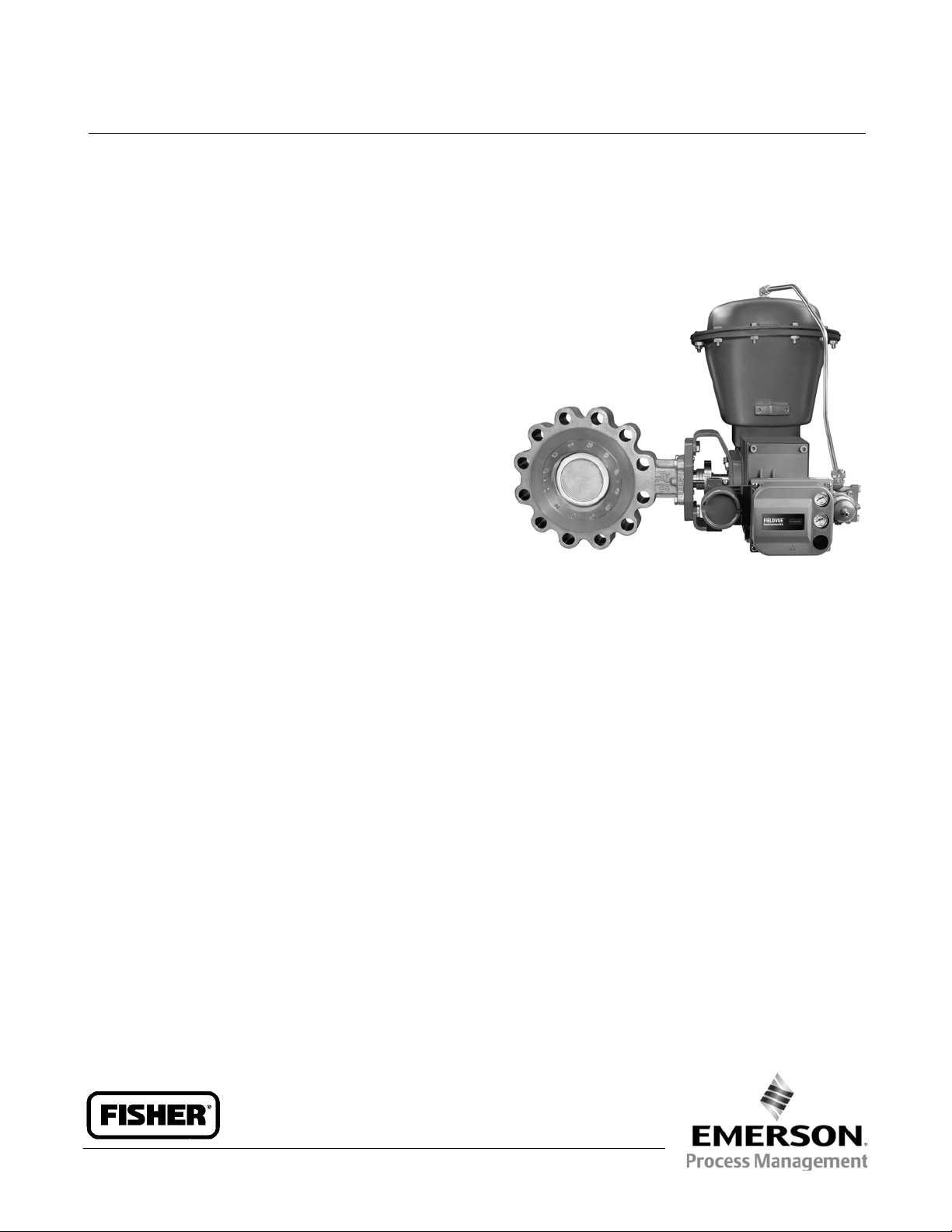
Fisherr POSI-SEALt A11
High-Performance Butterfly Valve
The Fisher A11 High-Performance Butterfly Valve
maintains tight shutoff, and can be specified for a wide
range of pressure and temperature conditions,
including cryogenic applications.
TheA11valveisavailableineitherawaferora
single-flange design (single-flange only for CL600, 900,
and 1500). A square or keyed shaft can combine with a
variety of handlevers, handwheels, or pneumatic
piston diaphragm actuators. A splined shaft can
combine with a variety of spring-and- diaphragm or
pneumatic piston actuators. These combinations help
make the A11 valve a reliable, high-performance
butterfly valve for both throttling and on-off
applications in the process industries.
Product Bulletin
21.1:A11
May 2013
The A11 valve can be supplied with one of several
dynamic seals (figure 1) that can be used in a variety of
demanding applications. With the appropriate seal
selection and materials of c onstruction, the
pressure-assisted seal helps provide excellent shutoff
against the full ASME class pressure range for the A11
valve.
Features
Shaft Versatility– This valve will meet your actuator
needs with a choice of square, keyed, or splined
shaft connections.
Excellent Shutoff Integrity–The pressure-assisted
seal design provides tight shutoff and permits the
use of smaller, less expensive actuators in
applications requiring full ASME B16.34 shutoff
capabilities.
W9570-1
Excellent Emissions Capabilities– The optional
ENVIRO-SEALt packing systems are designed with
very smooth shaft surfaces and live-loading to
provide improved sealing, guiding, and loading
force transmission. The seal of the ENVIRO-SEAL
system can control emissions to below 100 ppm
(parts per million).
Sour Service Capability– Trim and bolting materials
are available for applications involving sour liquids
and gases. These constructions comply with NACE
MR0175-2002, MR0103, and MR0175 / ISO 15156.
High-Temperature/Cryogenic Capabilities–
Optional valve constructions allow this valve to
meet both high-temperature and cryogenic
applications (see table 7 for cryogenic and
high-temperature actuator configurations).
Easy Installation–The valve body self-centers on the
line flange bolts as a fast, accurate means of
centering the valve in the pipeline.
www.Fisher.com
Page 2

Product Bulletin
21.1:A11
May 2013
A11 Valve
D500203X012
Features (continued)
Reliable Flange Gasketing Surface–Seal retainer
screws are located so there is no interference with
the sealing function of either flat sheet or spiral
wound line flange gaskets.
True Bidirectional Shutoff Performance–Afeature
of the valve design is that the torque necessary to
openandclosethevalveisthesameregardlessof
the direction in which the differential pressure is
applied.
Ease of Maintenance–Interchangeability of all parts,
including shafts and discs, simplifies service and
reduces maintenance costs.
Standard Seal
Configurations
Standard Soft Seal (PTFE CL150 and 300, and ETFE
CL600, 900, and 1500)–A resilient dynamic seal
with an elastomeric back-up ring for low to
moderate temperature applications.
Metal Seal–This stainless steel seal is available for
severe service and high-temperature applications to
704_C (1300_F) for NACE applications and 816_C
(1500_F) for other applications.
NOVEX Seal–The NOVEX stainless steel seal is
available for severe service, Cryogenic, and
high-temperature applications to 816_C (1500_F).
Available for CL150/150, 150, and 300, up to
NPS 36 only.
Phoenix III Seal–This three-component,
metal-and-polymeric seal is available for severe
service with low to moderate temperature
applications.
High-Pressure Seal (CL600, 900, and 1500)–This
robust, stainless steel seal is available for severe
service, cryogenic, and high-temperature
applications to 704_C (1300_F), for NACE, and for
other applications to 816_C (1500_F).
Cryo-Tight Cryogenic Seal–This resilient dynamic
seal is available with or without an aluminum
back-up ring for low temperature applications.
Table of Contents
Features 1.....................................
Standard Seal Configurations 2...................
Specifications 3................................
Installation 4..................................
Dimensions and Weights 9.......................
Pressure Drops 16..............................
2
Page 3

A11 Valve
D500203X012
Specifications
Product Bulletin
21.1:A11
May 2013
Available Configurations and Sizes
J Flangeless (wafer) or J Single-flange (lugged)
Available Sizes and Shaft Styles
PRESSURE
RATING
CL150/150
(1)
CL150 30 to 72 --- --CL300 30 to 72 --- ---
CL600
CL900
CL1500
CL2500 Consult your Emerson Process Management Sales Office
1. Refers to a valve construction consisting of a CL150 body and trim suitable for a
shutoff pressure drop of 150 psid.
Keyed Square Splined
30 to 72 --- ---
14 to 48
(standard),
3to12
(optional)
12 to 24
(standard),
6to10
(optional)
10 to 20
(standard)
VALVE SIZE, NPS
3to12
(optional)
6to10
(standard)
---
3to12
(standard)
14 to24
(optional)
Consult your
Emerson Process
Management
sales office
Maximum Temperature Capabilities
See table 1
High-Temperature and Cryogenic Applications: See
table 7 for available valve and actuator combinations
Shutoff Classification per ANSI/FCI 70-2andIEC
60534-4
Standard Soft Seal: Bubble-tight shutoff (exceeds
Class VI)
Metal Seal: 20% of Class IV (reverse direction only)
NOVEX Seal: Standard Class V (Class VI optional,
reverse direction only)
Phoenix III Seal: Bubble-tight (reverse direction only),
Class VI (forward direction only)
High Pressure Seal: Standard Class V (Class VI
optional, reverse direction only)
Cryogenic Seal (Reverse direction only): NOVEX: Class
VI
CTFE: 10% of Class IV
CTFE with Aluminum Backup Ring: Class VI
End Connection Style
Flangeless or single flange style designed t o fit
between raised-face mating flanges of appropriate
class pressure rating
ASME B16.5
NPS 3 through 24: CL600
Flow Characteristic
Modified equal percentage
Flow Coefficients
See Fisher Catalog 12
NPS 6 through 24: CL900
NPS 10 through 20: CL1500
ASME B16.47 Class A and MSS-SP-44
NPS 30 through 48: CL150, 300, and 600
NPS 30 through 36: CL900
Consult your Emerson Process Management sales
office for valves compatible with API 605 and ASME
B16.47 Class B flanges
Maximum Inlet Pressure
(1)
Valve Body: Consistent with CL150, 300, 600, 900,
and 1500 pressure/temperature ratings per ASME
Noise Levels
See Fisher Catalog 12 for sound pressure level
prediction
Available Actuators
Handlever; handwheel; or pneumatic piston, spring
return, double-acting, spring and diaphragm
Disc Rotation
Clockwise (CW) to close
B16.34, see table 17
Seal: seefigure1
Materials of Construction
See table 1
Disc Hard Surfacing: All CL600, 900, and 1500 disc
edges must be coated, regardless of the seal type.
Metal, NOVEX, Phoenix III and cryogenic seals require
the disc to be coated, regardless of the valve class.
1. The pressure/temperature limits in this bulletin, and any applicable codeor standard limitation, should no t be exceeded.
Valve Dimensions and Approximate Weights
See figures 3, 4, 5, 6 and 7
For general packing guidelines, see Bulletin 59.3:042
Packing Selection Guidelines for Rotary Valves,
D102093X012
For information on ENVIRO-SEAL packing system see
Bulletin 59.3:041 ENVIRO-SEAL Packing Systems for
Rotary Valves, D101638X012
(1)
3
Page 4
Product Bulletin
21.1:A11
May 2013
A11 Valve
D500203X012
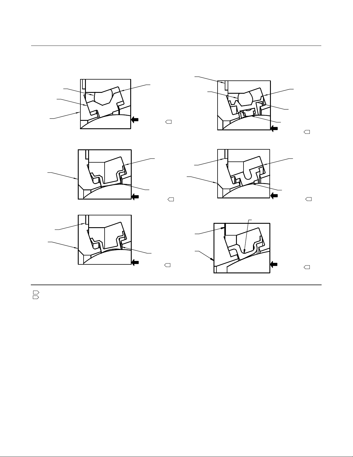
Figure 1. Available Seal Configurations
BACK-UP
RING
SEAL RING
RETAINING
RING
RETAINING
RING
GRAPHITE
GASKET
RETAINING
RING
E0578
BODY
VALVE DISC
SOFT SEAL WITH
BACK-UP O-RING
BODY BODY
VALVE DISC
NOVEX SEAL
BODY
VALVE DISC
METAL SEAL
LARGEST
OUTSIDE
DIAMETER
HIGH PRESSURE
AT SHUTOFF
LARGEST
OUTSIDE
DIAMETER
SEAL
RING
HIGH PRESSURE
AT SHUTOFF
SEAL
RING
HIGH PRESSURE
AT SHUTOFF
2
1
1
GRAPHITE
GASKET
GRAPHITE
GASKET
RETAINING
RING
GRAPHITE
GASKET
RETAINING
RING
BACK-UP
RING
BODY
VALVE DISC
PHOENIX III
FIRE-SAFE SEAL
VALVE DISC
CRYOGENIC SEAL
HPS
SEAL RING
BODY
VALVE DISC
HIGH-PRESSURE SEAL (HPS)
Notes:
1
This unidirectional seal must be installed so that the retaining ring is downstream from the high pressure side of the valve at shutoff, as shown.
2
For this bidirectional seal, the “preferred” valve orientation places the retaining ring downstream from the high pressureside ofthe valveat shutoff.
LARGEST
OUTSIDE
DIAMETER
SEAL
RING
RESILIENT
INSERT
HIGH PRESSURE
AT SHUTOFF
LARGEST
OUTSIDE
DIAMETER
CRYOGENIC
SEAL RING
HIGH PRESSURE
AT SHUTOFF
HIGH PRESSURE
AT SHUTOFF
1
1
1
Installation
Preferred valve orientation for the A11 valve is reverse
flow direction. Reverse flow direction is into the side of
the valve body opposite the retaining ring or into the
shaft side of the disc.
For erosive and many severe service applications,
valves with bidirectional seals can and should be
installed with the shaft horizontal and in the forward
flow direction to prevent direct impingement of the
process media on the seal, and to minimize the
exposure of the shaft bearings to the process media.
4
The standard soft seal and the Phoenix III seal both
offer bidirectional shutoff. Valves using either metal,
NOVEX, or cryogenic seals are unidirectional and must
be installed in the reverse flow orientation.
For assistance in selecting the appropriate
combination of actuator action and open valve
position, consult your Emerson Process Management
sales office.
Dimensions and weights for wafer-style and
single-flangevalvesareshowninfigures3,4,5,6,
and 7.
Page 5
Product Bulletin
A11 Valve
D500203X012
Table 1. Material Temperature Ranges
PART NAME MATERIAL TEMP _C TEMP _F
WCC Steel, SA-516-70 or SA-105 -29 to 427 -20 to 800
(2)
(2)
Valve Body
(5)
Disc
(1)
CF8M, CF8C, CF8
CF8M, CF8C, CF8
Disc Seating Surface
Coating
Shaft
(3)
Bearings
Seal Ring
Backup Ring
Packing
Square Ring Graphite for Non-oxidizing Service -254 to 816 -425 to 1500
1. Special gasket retainer bolts are required for over 538_C (1000_ F).
2. Special retainingring screws for single flange valves over 538_C (1000_F).
3. Special thrustbearings are required for high temperature applications over 343_C (650_F) (with 6 and 12 inch extensions). Constructions with carbon steel valvesand SST discs may require
special thrust bearingsat temperatures greater than 343_C(650_F).
4. Special option; contact your Emerson Process Managementsales office.
5.ForvalvesNPS30andlargerattemperaturesover254_C(450_F),thediscmaterialshouldbethesameasthevalvebodymaterial.
CF8M,CF8,CF3M,CF3 -254 to 538 -425 to 1000
FMS 20B16 a Fisher material standard (0.04% min carbon)
over 538 to 816 over 1000 to 1500
LCC -45 to 343 -50 to 650
C12A -29 to 649 -20 to 1200
WC9 -29 to 593 -20 to 1100
CG8M, CG3M, CF8C -198 to 538 -325 to 1000
WCC S teel -29 to 427 -20 to 800
CF8M,CF8,CF3M,CF3 -254 to 538 -425 to 1000
FMS 20B16 a Fisher material standard (0.04% min carbon)
over 538 to 816 over 1000 to 1500
CB7Cu-1 -29 to 427 -20 to 800
CG8M, CG3M, CF8C -198 to 538 -325 to 1000
Chrome Plating -254 to 316 -425 to 600
Chromium Coat per FFS 2E1 -254 to 593 -425 to 1100
Electroless Nickel Coating(ENC) -254 to 343 -425 to 650
Chromium Carbide Coating
CoCr-A(Alloy6)
(4)
-254 to 816 -425 to 1500
S17400 (H1025) -73 to 427 -100 to 800
S17400 (H1150M) -196 to 427 -320 to 800
(4)
N05500
-254 to 482 -425 to 900
N07718 -254 to 704 -425 to 1300
(4)
S20910
N07750
(4)
-254 to 593 -320 to 1100
over 593 to 816 over 1100 to 1500
PEEK -73 to 260 -100 to 500
PTFE Composition -254 to 163 -425 to 325
S31600 (316 SST Nitrided)
R30006 (Alloy 6)
Bronze
PTFE Lined N04400
(4)
(4)
(4)
-254 to 816 -425 to 1500
-254 to 302 -425 to 575
-254 to 232 -425 to 450
Soft - PTFE -62 to232 -80 to 450
Soft - ETFE -54 to 149 -65 to 300
Metal - All See table 2
HPS - S20910
(4)
-254 to 649 -425 to 1200
Used with Soft Seal
Fluorocarbon -29 to 204 -20 to 400
EPR -54 to 182 -65 to 360
(4)
Nitrile
Chloroprene
(4)
-29 to 93 -20 to 200
-43 to 149 -45 to 300
Used with Phoenix III Seal
Fluorocarbon -40 to 232 -40 to 450
EPR -62 to 204 -80 to 400
(4)
Nitrile
Chloroprene
(4)
-40 to 149 -40 to 300
-54 to 149 -65 to 300
Used with Cryogenic Seal
Aluminum
(4)
-254 to 149 -425 to 300
PTFE V-Ring -254 to 232 -425 to 450
PTFE ENVIRO-SEAL -254 to 232 -425 to 450
Square Ring Graphite for Oxidizing Service -254 to 538 -425 to 1000
Graphite ENVIRO-SEAL -140 to 315 -325 to 600
21.1:A11
May 2013
5
Page 6
Product Bulletin
21.1:A11
May 2013
Table 2. Temperature Limits for Metal Seal
MAXIMUM
SEAL TYPE PRESSURE RATING SEAL MATERIAL
S31600 w/CF8M disc
S31600 w/WCC disc
S31600 w/CF8M disc
S31600 w/WCC disc
(2)
(2)
S20910 NACE w/ CF8M disc
S20910 w/WCC disc
S17400 H1150Mw/ CF8M disc
Metal
CL150/150, and150
300
(1, 2)
600
(2)
S17400 H1150Mw/ WCCdisc
1. When used with CF8M discs, S20910 is the preferred seal material. When usedwith WCC discs, S17400H1150M is the preferred material.
2. For valves with WCC discs at temperatures over 254_C (450_F),contact your Emerson Process Management salesoffice for seal materialselection.
Table 3. Trim Descriptions - CL600
Trim Type
Trim
Number
500
502
Standard
504
506
High-
Temperature
514H
516H
Cryogenic 517C
1. Trim 500 is furnished as standard trim in all CL600 A11 valves.
2. If operating temperature is above 343_C(650_F), see table 7for available actuator configurations.
3. Trim includes6-inch shaft extension.
4. Trim includes12-inch shaft extension.
5. Trim includes Cryogenic shaft extension, see table6 for extension length.
(1)
(2)
(3)
(4)
(5)
Temperature
Range
-29 to149_C
-20 to 300_F
-46 to232_C
-50 to 450_F
-40 to149_C
-40 to 300_F
-46 to427_C
-50 to 800_F
-46 to427_C
-50 to 800_F
-46 to538_C
-50 to 1000_F
-196 to163_C
-320 to325_F
Disc
Material
Disc Edge Coating Seal Type Seal Material Shaft Bearings Packing
CF8M Chrome Plated Soft ETFE S17400 H1025 PEEK PTFE
CF8M Chrome Plated Metal S20910 S17400 H1025 PEEK PTFE
CF8M Chrome Plated Phoenix III S31600/ETFE S17400 H1025 PEEK PTFE
CF8M
CF8M
CF8M
CF8M Chrome Plated HPS
Chromium Coat per
FFS 2E1
Chromium Coat per
FFS 2E1
Chromium Coat per
FFS 2E1
Metal S20910 S17400 H1025
Metal S20910 S17400 H1025
Metal S21800 N07718
S20910
Nitrided
TEMPERATURE LIMITS
_C _F
538
232
816
232
649
232
232
427
S17400 H1150M
1000
450
1500
450
1200
450
450
800
Composition
A11 Valve
D500203X012
BACKUP RING
316 SST
Nitrided
316 SST
Nitrided
316 SST
Nitrided
PTFE
No
No
No
No
Graphite
Graphite
Graphite
PTFE
Table 4. Trim Descriptions - CL900 and CL1500
Trim Type
Trim
Number
500
502
Standard
504
506
High-
Temperature
1. Trim 500 is furnished as standard trim in all CL1500 A11 valves.
2. If operating temperature is above 343_C(650_F), see table 7for available actuator configurations.
3. Trim includes6-inch shaft extension.
4. Trim includes12-inch shaft extension.
5. Consult Fisher bulletin 59.3:042 (D102093X012) for packing selection guidelinesregarding pressure/temperaturelimits.
514H
516H
6
(1)
(2)
(3)
(4)
Temperature
Range
-29 to149_C
-20 to 300_F
-46 to232_C
-50 to 450_F
-40 to149_C
-40 to 300_F
-46 to427_C
-50 to 800_F
-46 to427_C
-50 to 800_F
-46 to538_C
-50 to 1000_F
Disc
Material
Disc Edge Coating Seal Type Seal Material Shaft Bearings Packing
CB7Cu-1 Chrome Plated Soft ETFE S17400 H1025 PEEK PTFE
CB7Cu-1 Chrome Plated HPS
CB7Cu-1 Chrome Plated Phoenix III S31600/ETFE S17400 H1025 PEEK PTFE
CB7Cu-1
CB7Cu-1
CF8M
Chromium Coat per
FFS 2E1
Chromium Coat per
FFS 2E1
Chromium Coat per
FFS 2E1
HPS
HPS
HPS
S20910
Nitrided
S20910
Nitrided
S20910
Nitrided
S21800
Nitrided
S17400 H1025 PEEK PTFE
S17400 H1025
S17400 H1025
N07718
316 SST
Nitrided
316 SST
Nitrided
316 SST
Nitrided
Graphite
Graphite
Graphite
(5)
Page 7

A11 Valve
D500203X012
Table 5. Trim Descriptions - CL150/150, CL150, and CL300
Trim Type
Standard
High-
Temperature
Cryogenic 567C
1. Trim 550 is furnished as standard trim in all CL150/150, 150, and 300 A11 valves.
2. If operating temperature is above 343_C(650_F), see table 7for available actuator configurations.
3. Trim includes6-inch shaft extension.
4. Trim includes12-inch shaft extension.
5. Trim includes Cryogenic shaft extension, see table6 for extension length.
6. NPS 42 and 48 will have an S31600 metal seal ring in place ofthe S31600 NOVEX seal ring.
Trim
Number
550
552
554
555
556
564H
566H
(1)
(2)
(3)
(4)
(5)
Temperature
Range
-29 to204_C
-20 to 400_F
-46 to232_C
-50 to 450_F
-40 to232_C
-40 to 450_F
-46 to316_C
-50 to 600_F
-46 to427_C
-50 to 800_F
-46 to427_C
-50 to 800_F
-46to538_C
- 50 to 1000_F
-196 to163_C
-320 to325_F
Disc
Material
CF8M or
WCC
CF8M or
WCC
CF8M or
WCC
CF8M or
WCC
CF8M or
WCC
CF8M or
WCC
CF8M
CF8M Chrome Plated NOVEX
Disc Edge Coating Seal Type Seal Material Shaft Bearings Packing
None Soft PTFE S17400H1025 PEEK PTFE
Chrome Plated NOVEX
Chrome Plated Phoenix III S31600/PTFE S17400 H1025 PEEK PTFE
Chrome Plated NOVEX
Chromium Coat per
FFS 2E1
Chromium Coat per
FFS 2E1
Chromium Coat per
FFS 2E1
NOVEX
NOVEX
NOVEX
Product Bulletin
(6)
S31600 S17400 H1025 PEEK PTFE
(6)
S31600 S17400 H1025
(6)
S31600 S17400 H1025
(6)
S31600 S17400 H1025
(6)
S31600 N07718
(6)
S31600 S17400 H1150M
316 SST
Nitrided
316 SST
Nitrided
316 SST
Nitrided
316 SST
Nitrided
PTFE
Composition
21.1:A11
May 2013
Graphite
Graphite
Graphite
Graphite
PTFE
Table 6. Cryogenic Shaft Extension Lengths
CRYOGENIC EXTENSION LENGTH, INCH FOR VALVE BODY SIZE, NPS
3 4 6 8 10 12 14 16 18 20 24 30 36 42 48
14-3/4 17-3/4 19-1/4 26-3/4 28-1/2 33-1/2 36 36 36 36 36 36 36 36 36
1. Extension lengthmeasured from center ofvalve body to bottom of packing flange.
(1)
Note
Trim will include the standard disc material included in the
FS number selected. If the trim number indicates only a
CF8M disc, the trim cannot be used with an FS number
including a WCC disc.
7
Page 8

Product Bulletin
21.1:A11
May 2013
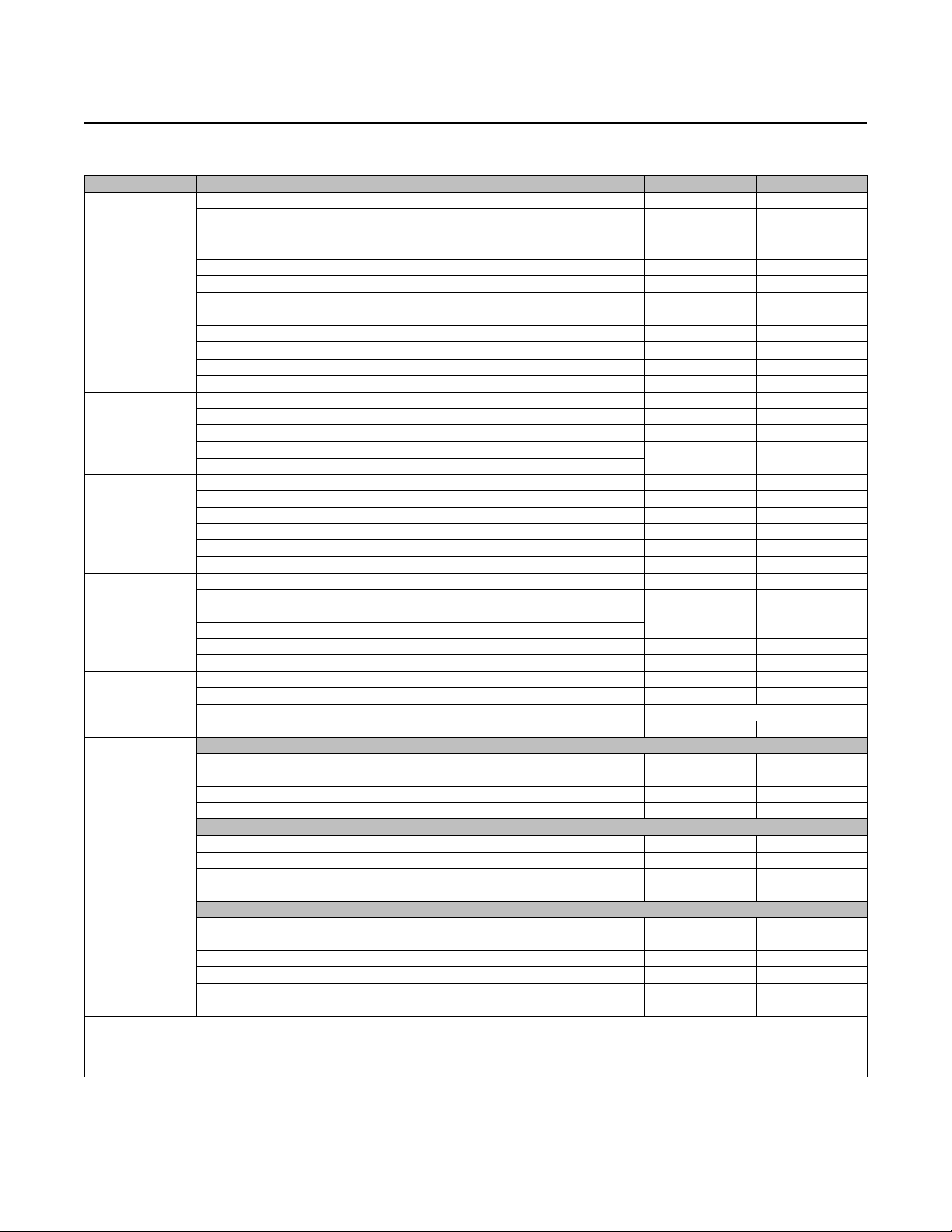
Table 7. Valve/Actuator Combinations
TEMPERATURE RANGE
-254 to-196_C
(-425 to-320_F)
-196 to-46_C
(-320 to-50_F)
-46 to343_C
(-50 to650_F)
343 to426_C
(650 to800_F)
426 to538_C
(800 to1000_F)
538 to816_C
(1000 to1500_F)
1. Select splined shaft option when necessary (standardfor NPS 3-12 CL600valves).
2. See figure 2 for actuator mounting positions.
3. Select keyed shaft option when usingBettis “G” Series Actuator, NPS 6-12.
4. Consult your Emerson ProcessManagement sales office.
5. Select square shaft option when using FieldQ or 1035 actuators.
Valve with cryogenic extension and special trim
materials
Valve with cryogenic extension and trim and
Valve (select appropriate trim) and standard
Mounting positions 1 and 3: Valve (select
appropriate trim) and standard actuator
Mounting positions 2 and 4: Valve with 6-inch
extension (select trim 514H or 564H) and
standard actuator - ambient temperature may
dictate the need for a high-temperature
Mounting positions 1 and 3: Valve (select
appropriate trim) and standard actuator
Mounting positions 2 and 4: Valve with 6-inch
extension (select trim 564H or 514H with N07718
shaft) and standard actuator - ambient
temperature may dictate the need for a
Valve with 12-inch extension and special trim
materials
1052, 1061, or 2052
(4)
and standard actuator
(1, 2)
standard actuator
actuator
diaphragm
high-temperature diaphragm
(4)
and standard actuator
SELECTION GUIDELINES
Bettis™
Valve withcryogenic extension and special trim
materials
Valve with cryogenic extension and trim and
Valve (select appropriate trim) and standard
Valve (select appropriate trim) and actuator with
Valve with 6-inch extension(select trim514H)
Valve (select appropriate trim) and actuator with
Valve with 6-inch extension (select trim 564H or
514H withN07718 shaft) and standard actuator
Valve with 12-inch extension and special trim
materials
A11 Valve
D500203X012
(3)
, FieldQt
high-temperature O-rings option
high-temperature O-rings option
(5)
(5)
, 1035
(4)
and standard actuator
standard actuator
actuator
or
and standard actuator
or
(4)
and standard actuator
,orHytorkXL
Figure 2. Mounting Styles and Positions
STYLE D
4
33
STYLE A
NORMAL
FLOW
GE37285
4
POSITION 1
STANDARD
2
3
POSITION 1
STANDARD
2
STYLE C
POSITION 1
STANDARD
4
2
NORMAL
FLOW
STYLE B
POSITION 1
STANDARD
4
2
3
8
Page 9

Product Bulletin
A11 Valve
D500203X012
Table 8. Dimensions and Weights Wafer and Single Flange Style CL150/150
Wafer
A
Single
Flange
B C D E F H J K L
mm kg
See
Thread
Info
Below
Inches lbs
76.2
Thread
Below
See
Info
(1)
M
744 57.2 12.7 528
R
VALVE
SIZE,
NPS
30 864 994 121 559 516 295 95.25 337
36 1029 1178 149 683 613 295 95.25 337 76.2 888 57.2 12.7 806
42 1207 1356 210 762 695 314 114.3 337 76.2 1032 69.9 15.9 1302
48 1364 1524 229 889 826 314 114.3 305 152 1180 69.9 15.9 1904
30 34.00 39.12 4.75 22.00 20.31 11.62 3.75 13.25 1-1/4-8 3.00 7/8-9 29.30 2.25 1/2 1164
36 40.50 46.38 5.88 26.88 24.12 11.62 3.75 13.25 1-1/2-8 3.00 7/8-9 34.96 2.25 1/2 1778
42 47.50 53.38 8.25 30.00 27.38 12.38 4.5 13.25 1-1/2-8 3.00 7/8-9 40.64 2.75 5/8 2871
48 53.69 60.00 9.00 35.00 32.50 12.38 4.5 12.00 1-1/2-8 6.00 1-1/4-7 46.47 2.75 5/8 4198
1. M dimensionis disc chordal swing diameter.
Figure 3. Dimensions Wafer and Single Flange Style CL150/150 (also see table 8)
21.1:A11
May 2013
KEY SQ
SIZE
APPROX
WEIGHT
D
C
E
B
NPS 48 ONLY
H
H
F
H
K
L
R
A
L
4HOLES,JDIA.
K
DC
E
F
13B4598-D
13B4556-D
B2633-1
JDIA.
R
A
9
Page 10

Product Bulletin
21.1:A11
May 2013
Table 9. Dimensions and Weights Wafer and Single Flange Style CL150
Wafer
A
Single
Flange
B C D E F H J K L
mm kg
76.2
See
Thread
Info
Below
Inches lbs
Thread
Below
(1)
M
735.8 69.9 15.9 528
See
Info
VALVE
SIZE,
NPS
30 866.6 991 158.8 590.6 520.7 314.5 114.3 336.6
36 1031.7 1175 177.8 657.4 619.3 314.5 114.3 304.8 152.4 887.7 69.9 15.9 806
42 1050 1360 228.6 838.2 730.3 314.5 114.3 304.8 152.4 1028.2 69.9 15.9 1302
48 1371.6 1524 260.4 901.7 797.1 314.5 114.3 508.0 203.2 1110.9 69.9 15.9 1904
30 34.12 39.00 6.25 23.25 20.50 12.38 4.5 13.25 1-1/4-8 3.00 7/8-9 28.97 2-3/4 5/8 1164
36 40.62 46.25 7.00 25.88 24.38 12.38 4.5 12.00 1-1/2-8 6.00 1-1/4-7 34.95 2-3/4 5/8 1778
42 47.50 53.56 9.00 33.00 28.75 12.38 4.5 12.00 1-1/2-8 6.00 1-1/4-7 40.48 2-3/4 5/8 2871
48 54.00 60.00 10.25 35.50 31.38 12.38 4.5 20.00 1-1/2-8 8.00 1-1/4-7 46.09 2-3/4 5/8 4198
1. M dimensionis disc chordal swing diameter.
Figure 4. Dimensions Wafer and Single Flange Style CL150 (also see table 9)
A11 Valve
D500203X012
KEY SQ
R
SIZE
APPROX
WEIGHT
D
JDIA.
DC
A
C
E
F
LDIA.
RDIA.
H
E
F
R
B
K
H
K
10
13B4160-A
13B4443-D
B2377-2
ADIA.
4HOLES,JDIA.
NPS 36, 42 and 48
Page 11

Product Bulletin
A11 Valve
D500203X012
Table 10. Dimensions and Weights Wafer and Single Flange Style CL300
Wafer
A
Flange
Single
B C D E F H J K L M
mm kg
203
See
Thread
Info
Below
Inches lbs
See
Thread
Info
Below
(1)
R
681 70 15.9 952
VALVE
SIZE
NPS
30 865 1105 241 648 576 314 114.3 508
36 1035 1286 27 3 740 675 353 152.4 432 203 838 95 22.2 1315
42 1162 1346 29 9 867 768 363 163.6 432 203 943 102 25.4 2263
48 1315 1484 42 2 934 888 497 114.3 660 330 1125 146 38.1 3056
30 34.06 43.50 9.50 25.50 22.69 12.38 4.5 20.00 1-3/4-8 8.00 1-1/4-7 26.80 2-3/4 5/8 2100
36 40.75 50.62 10.75 29.12 26.56 13.88 6 17.00 2-8 8.00 1-1/4-7 32.99 3-3/4 7/8 2900
42 45.75 53.00 11.75 34.12 30.25 14.31 6.44 17.00 1-5/8-8 8.00 1-1/4-7 37.13 4 1 4989
48 51.75 58.44 16.62 36.75 34.94 19.56 4.5 26.00 1- 7/8-8 13.00 1-1/4-7 44.29 5-3/4 1-1/2 6738
1. M dimensionis disc chordal swing diameter.
21.1:A11
May 2013
KEY SQ
SIZE
APPROX
WEIGHT
Figure 5. Dimensions Wafer and Single Flange Style CL300 (also see table 10)
ADIA.
13B4054-B
A6048-2/IL
ADIA.
13B4157-A
A6052-2
D
CE
F
RDIA.
JDIA.
D
C
E
F
RDIA.
4HOLES,JDIA.
LDIA.
K
H
LDIA.
B
K
H
B
LDIA
254
(10)
NPS 36 and 42
451.2
(18)
LDIA
LDIA
H
K
NPS 30
H
K
109.5
(4.31)
H
K
NPS 48
11
Page 12

Product Bulletin
21.1:A11
May 2013
Table 11. Dimensions and Weights Single Flange Style CL600
VALVE
SIZE,
NPS
A B C D
Keyed
Shaft
E F
Splined
Shaft
Sq
Shaft
Keyed
Shaft
Splined
Shaft
G
Square
H K
(1)
M
mm kg
3 213 46 146 83 210 187 57 66.68 67 10.3 89 --- 64 12.7
4 276 61 178 105 210 214 67 66.68 73 15.9 114 --- 86 15.9 19.1 4.8 10
6 346 73 235 156 210 214 90 66.68 86 22.2 114 --- 127 25.4 25.4 6.4 25
8 424 89 260 230 210 208 90 66.80 92 25.4 127 51 182 31.8 38.1 6.4 52
10 521 114 321 282 210 356 95 66.80 156 34.9 127 51 221 38.1 44.5 9.5 113
12 569 140 356 318 210 356 95 73.15 156 34.9 273 51 260 44.5 44.5 9.5 153
14 613 159 371 343 295 356 --- 95.25 156 --- 337 76.2 282 57.2 50.8 12.7 186
16 689 178 432 384 314 356 --- 114.3 156 --- 337 76.2 321 69.9 55.9 15.9 274
18 752 197 476 430 314
20 823 229 508 449 314
24 946 229 562 524 314
(2)
(2)
(2)
--- 114.3
--- 114.3
--- 114.3
(2)
(2)
(2)
--- 305 152.4 371 69.9
--- 305 152.4 399 69.9
--- 508 203.2 516 69.9
Inches lbs
3 8.38 1.81 5.75 3.25 8.25 7.38 2.25 2.625 2.62 13/32 3.50 --- 2.52 1/2
4 10.88 2.38 7.00 4.12 8.25 8.44 2.62 2.625 2.88 5/8 4.50 --- 3.40 5/8 3/4 3/16 23
6 13.62 2.88 9.25 6.12 8.25 8.44 3.56 2.625 3.38 7/8 4.50 --- 4.98 1 1 1/4 54
8 16.69 3.50 10.25 9.06 8.25 8.19 3.56 2.63 3.63 1 5.00 2.00 7.17 1-1/4 1-1/2 1/4 115
10 20.50 4.50 12.62 11.12 8.25 14.00 3.75 2.63 6.13 1-3/8 5.00 2.00 8.70 1-1/2 1-3/4 3/8 249
12 22.38 5.50 14.00 12.50 8.25 14.00 3.75 2.88 6.13 1-3/8 10.75 2.00 10.22 1-3/4 1-3/4 3/8 337
14 24.12 6.25 14.62 13.50 11.63 14.00 --- 3.75 6.13 --- 13.25 3.00 11.09 2-1/4 2 1/2 410
16 27.12 7.00 17.00 15.12 12.38 14.00 --- 4.5 6.13 --- 13.25 3.00 12.63 2-3/4 2-1/2 5/8 605
18 29.62 7.75 18.75 16.94 12.38
20 32.38 9.00 20.00 17.69 12.38
24 37.25 9.00 22.12 20.62 12.38
1. M dimension is the disc chordal swing diameter.
2. Consult your Emerson ProcessManagement sales office.
(2)
--- 4.5
(2)
--- 4.5
(2)
--- 4.5
(2)
(2)
(2)
--- 12.00 6.00 14.62 2-3/4
--- 12.00 6.00 15.71 2-3/4
--- 20.00 8.00 20.32 2-3/4
R
Keyed Splined
14.2 x
15.9
9/16 x
A11 Valve
D500203X012
KEY SQ
SIZE
3.2 9
(2)
15.9 361
(2)
15.9 526
(2)
15.9 669
1/8 20
5/8
(2)
5/8 796
(2)
5/8 1160
(2)
5/8 1475
APPROX
WEIGHT
Table 12. Dimensions Single Flange Style CL600
VALVE SIZE, NPS
3-24 See Thread Info Below See Thread Info Below
VALVE SIZE, NPS Inches
3 0.53 3/4-108holes
4 0.53 7/8-98holes
6 0.53 1-812holes
8 1/2-13 1-1/8-812holes
10 3/4-10 1-1/4-816holes
12 3/4-10 1-1/4-820holes
14 7/8-9 1-3/8-820holes
16 7/8-9 1-1/2-820holes
18 1-1/4-7 1-5/8-820holes
20 1-1/4-7 1-5/8-824holes
24 1-1/4-7 1-7/8-824holes
L P
mm
12
Page 13

A11 Valve
D500203X012
Figure 6. Dimensions Single Flange Style CL600 (also see table 11)
Product Bulletin
21.1:A11
May 2013
PDIA.
13B4151-A
B2379-2
D
C
NPS 3 THROUGH 6 SINGLE FLANGE
ADIA.
E
F
4HOLES,
13.5(0.53) DIA.,
THRU ON AN H
DIA. CIRCLE
Figure 7. Dimensions Single Flange Style CL600 (also see table 11)
CD
E
F
Gsq
B
M
mm
(INCH)
B
3/4 INCH
8-INCH ONLY
E
PDIA.
13B4156-A
A6053-2
RDIA.
ADIA.
H
NPS 8 THROUGH 24 SINGLE FLANGE
Gsq
DIMENSIONS FOR
SQUARE-END SHAFTS
4HOLES,
K
LDIA.
13
Page 14

Product Bulletin
21.1:A11
May 2013
Table 13. Dimensions and Weights Single Flange Style CL900
VALVE
SIZE,
NPS
6 381 76 233 233 210 90 67 22 235 46 126 25 6 59.0
8 470 109 305 305 210 90 67 35 273 51 164 38 10 120
10 546 146 353 353 210 95 67 35 273 51 182 44 10 210
12 610 229 445 445 295 --- 95 --- 337 76 165 57 13 450
14 635 216 451 451 295 --- 95 --- 337 76 208 57 13 444
16 705 241 438 438 314 --- 117 --- 337 76 217 70 16 513
18 781 273 524 524 314 --- 114 --- 337 76
20 857 292 695 695 314 --- 114 --- 305 165 284 70 16 991
24 1041 333 657 657 314 --- 117 --- 572 203 366 95 22 1628
6 15.00 3.00 9.19 9.19 8.25 3.56 2.62 0.87 9.25 1.812 4.98 1.00 1/4 130
8 18.50 4.31 12.00 12.00 8.25 3.75 2.62 1.37 10.75 2.00 6.46 1.50 3/8 264
10 21.50 5.75 13.88 13.88 8.25 3.75 2.62 1.37 10.75 2.00 7.17 1.75 3/8 463
12 24.00 9.00 17.50 17.50 11.62 --- 3.75 --- 13.25 3.00 6.48 2.25 1/2 993
14 25.00 8.50 17.75 17.75 11.62 --- 3.75 --- 13.25 3.00 8.17 2.25 1/2 978
16 27.75 9.50 17.25 17.25 12.38 --- 4.62 --- 13.25 3.00 8.55 2.75 5/8 1132
18 30.76 10.75 20.63 20.63 12.38 --- 4.50 --- 13.25 3.00
20 33.75 11.50 27.38 27.38 12.38 --- 4.50 --- 12.00 6.50 11.19 2.75 5/8 2185
24 41.00 13.12 25.88 25.88 12.38 --- 4.62 --- 22.50 8.00 14.40 3.75 7/8 3590
1. M dimension is the disc chordal swing diameter.
2. Contact your Emerson Process Management sales office.
A B C D
Keyed
Shaft
E
Sq Shaft
F
mm kg
Inches lbs
G
Square
H K M
(2)
(2)
R
(1)
Keyed
70 16 703
2.75 5/8 1550
A11 Valve
D500203X012
KEY SQ
SIZE
APPROX
WEIGHT
Table 14. Dimensions Single Flange Style CL900
VALVE SIZE, NPS
6
8
10
12
14
16
18
20
24
VALVE SIZE, NPS Inches
6 5/8-11 4 Holes 1-1/8-812Holes
8 3/4-10 4 Holes 1-3/8-812Holes
10 3/4-10 4 Holes 1-3/8-816Holes
12 7/8-94Holes 1-3/8-820Holes
14 7/8-94Holes 1-1/2-820Holes
16 7/8-94Holes 1-5/8-820Holes
18 1-1/4-76Holes 1-7/8-820Holes
20 1-1/4-76Holes 2-820Holes
24 1-1/4-76Holes 2-1/2-820Holes
L J
mm
See Thread Info Below See Thread Info Below
14
Page 15

Product Bulletin
A11 Valve
D500203X012
Table 15. Dimensions and Weights Single Flange Style CL1500
VALVE
SIZE,
NPS
10 584 178 399 399 295 95 337 76 118 57 13 311
12 673 267 445 445 305 105 337 76
14 754 283 483 483 210 114 337 76
16 826 321 559 559 314 152 305 152
18 914 349 629 629 379 164 508 203
20 991 410 682 682 404 171 508 203
10 23.00 7.00 15.69 15.69 11.62 3.75 13.25 3.00 4.63 2.25 1/2 685
12 26.50 10.50 17.50 17.50 12.00 4.13 13.25 3.00
14 29.69 11.13 19.00 19.00 8.25 4.50 13.25 3.00
16 32.52 12.63 22.00 22.00 12.38 6.00 12.00 6.00
18 36.00 13.75 24.75 24.75 14.94 6.44 20.00 8.00
20 39.00 16.13 26.84 26.84 15.89 6.75 20.00 8.00
1. M dimension is the disc chordal swing diameter.
2. The disc size is less than the face-to-face dimension ofthis valve. Therefore, the disc chordal swing is not applicable when sizing this valve.
A B C D
E
Keyed
Shaft
F H K
mm kg
Inches lbs
(1)
M
R Keyed
(2)
(2)
(2)
(2)
(2)
(2)
(2)
(2)
(2)
(2)
64 16 663
70 16 810
70 22 1152
102 25 1613
108 25 2250
2.50 5/8 1462
2.75 5/8 1785
2.75 7/8 2540
4.00 1 3555
4.25 1 4960
Table 16. Dimensions Single Flange Style CL1500
VALVE SIZE, NPS
10
12
14
16
18
20
VALVE SIZE, NPS Inches
10 7/8-94Holes 1-7/8-812Holes
12 7/8-94Holes 2-816Holes
14 7/8-94Holes 2-1/4-816Holes
16 1-1/4-76Holes 2-1/2-816Holes
18 1-1/4-76Holes 2-3/4-816Holes
20 1-1/4-76Holes 3-816Holes
See Thread Info Below See Thread Info Below
L J
mm
May 2013
KEY SQ
SIZE
21.1:A11
APPROX
WEIGHT
Figure 8. Dimensions Single Flange Style CL900 and CL1500 (also see tables 13 and 15)
A
D
C
J
E
F
R
L
K
H
B
15
Page 16

Product Bulletin
21.1:A11
May 2013
A11 Valve
D500203X012
Pressure Drops
table 17 for body limitations and tables 18, 19, 20, and
21 for trim limitations. Information on limits for
S31254, CW2M, M35-1 and other alloy constructions
Pressure drop limits of any given valve are based on
valve body, and trim material limits. To find the
appropriate pressure drop limitation, choose the
desired valve size and temperature range. Then search
can be obtained by contacting your Emerson Process
Management sales office. The lowest number from the
tables is the appropriate limit. The tables for both trim
and body limits must be consulted.
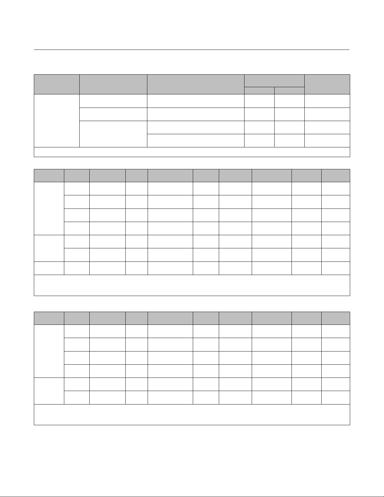
Table17.MaximumAllowableShutoffPressureDrops(Valve Ratings) Based on Carbon Steel and Stainless Steel
Valve Types
TEMPERATURE
RANGE
-254 to-29 --- 10.3 --- 19.0 --- 49.6 --- 99.3 --- 148.9 --- 248.2
-29 to 38 10.3 10.3 20 19.0 51.7 49.6 103.4 99.3 155.1 148.9 258.6 248.2
-450 to-20 --- 150 --- 275 --- 720 --- 1440 --- 2160 --- 3600
-20 to100 150 150 290 275 750 720 1500 1440 2250 2160 3750 3600
1000 --- 10 --- 20 --- 365 --- 725 --- 1090 --- 1820
1. For pressure/temperaturerating of other materials, contact your Emerson Process Management sales office.
(1)
(The tables for both trim and body limits must be consulted)
PRESSURE RANGE
CL150/150 CL150 CL300 CL600 CL900 CL1500
WCC CF8M WCC CF8M WCC CF8M WCC CF8M WCC CF8M WCC CF8M
_C Bar
93 9.3 9.0 17.9 16.2 51.7 42.7 103.4 85.5 155.1 128.2 258.6 213.4
149 8.3 7.9 15.9 14.8 50.3 38.6 100.3 77.2 150.7 115.8 251.0 192.7
204 7.2 7.2 13.8 13.4 48.6 35.5 96.9 70.7 145.5 106.2 242.7 177.2
260 6.2 6.2 11.7 11.7 45.9 33.1 91.7 65.8 137.6 98.9 229.3 164.8
316 5.2 5.2 9.7 9.7 41.7 31.0 83.4 62.1 125.1 93.4 208.6 155.5
343 4.5 4.5 8.6 8.6 40.7 30.3 81.0 61.0 121.7 91.4 202.7 152.4
371 4.1 4.1 7.6 7.6 38.3 30.0 76.5 60.0 114.8 90.0 191.3 149.6
399 3.4 3.4 6.6 6.6 34.8 29.3 70.0 59.0 104.8 88.3 174.8 147.2
427 2.8 2.8 5.5 5.5 28.3 29.0 56.9 58.3 85.2 87.2 141.7 145.5
454 --- 2.4 --- 4.5 --- 29.0 --- 57.6 --- 86.5 --- 144.1
482 --- 1.7 --- 3.4 --- 28.6 --- 57.2 --- 85.8 --- 143.1
510 --- 1.4 --- 2.4 --- 26.5 --- 53.4 --- 80.0 --- 133.1
538 --- 0.7 --- 1.4 --- 25.2 --- 50.0 --- 75.2 --- 125.5
_F Psi
200 135 130 260 235 750 620 1500 1240 2250 1860 3750 3095
300 120 115 230 215 730 560 1455 1120 2185 1680 3640 2795
400 105 105 200 195 705 515 1405 1025 2110 1540 3520 2570
500 90 90 170 170 665 480 1330 955 1995 1435 3325 2390
600 75 75 140 140 605 450 1210 900 1815 1355 3025 2255
650 65 65 125 125 590 440 1175 885 1765 1325 2940 2210
700 60 60 110 110 555 435 1110 870 1665 1305 2775 2170
750 50 50 95 95 505 425 1015 855 1520 1280 2535 2135
800 40 40 80 80 410 420 825 845 1235 1265 2055 2110
850 --- 35 --- 65 --- 420 --- 835 --- 1255 --- 2090
900 --- 25 --- 50 --- 415 --- 830 --- 1245 --- 2075
950 --- 20 --- 35 --- 385 --- 775 --- 1160 --- 1930
16
Page 17

A11 Valve
D500203X012
Product Bulletin
21.1:A11
May 2013
Table18.MaximumAllowableShutoffPressureDrops
CL150/150 CL150 CL300
Valve Body Size, NP S Valve BodySize, NPS Valve Body Size, NPS
(2)
,
(2)
,
TEMPERATURE
RANGE
30 36 42 48 30 36 42 48 30 36 42 48
_C Bar
-46 to 38 10.34 10.34 10.34 10.34 32.06 27.85 18.55 12.34 38.47 51.02 46.06 51.02
38 to 149 10.34 10.34 10.34 10.34 27.58 27.58 18.55 12.34 27.58 27.58 27.58 27.58
149 to 232 3.447 3.447 3. 447 3.447 3.447 3.447 3.447 3.447 3.447 3.447 3.447 3.447
-46 to 38 10.34 10.34 10.34 10.34 29.72 23.72 16.27 11.17 32.82 45.44 41.23 61.64
38 to 149 10.34 10.34 10.34 10.34 25.72 23.72 16.27 11.17 32.82 45.44 41.23 61.64
149 to 232 10.34 10.34 10.34 10.34 24.2 23.72 16.27 11.17 32.82 45.44 41.23 61.09
-46 to 38 10.34 8.136 10.34 4.964 21.24 16 9.584 5.792 26.48 35.78 31.37 48.06
38 to 149 10.34 8.136 10.34 4.964 17.93 16 9.584 5.792 26.48 35.78 31.37 39.64
149 to 232 10.34 8.136 10.34 4.964 16.75 16 9.584 5.792 20.68 20.68 20.68 20.68
-46 to 38 10.34 10.34 10.34 7.722 22.75 16.62 11.45 7.653 22.75 32.47 29.51 44.33
38 to 149 10.34 10.34 10.34 7.722 19.65 16.62 11.45 7.653 22.75 32.47 29.51 44.33
149 to 232 10.34 10.34 10.34 7.722 18.48 16.62 11.45 7.653 22.75 32.47 29.51 44.33
232 to 316 10.34 10.34 10.34 7.722 17.65 16.96 11.45 7.653 22.75 32.47 29.51 44.33
343 to 427 10.34 10.34 10.34 7.722 16.89 16.96 11.45 7.653 22.75 32.54 29.51 44.33
427 to 538 10.34 10.34 10.34 7.722 24.55 16.96 11.45 7.653 22.75 32.54 29.51 44.33
-196 to -46 10.34 10.34 10.34 10.34 26.34 28.89 20.82 14.34 41.78 55.23 46.61 56.95
-46 to 149 10.34 10.34 10.34 10.34 17.24 22.89 16.89 14.34 41.78 43.99 36.89 45.23
_F Psi
-50 to 100 150 150 150 150 465 404 269 179 558 740 668 740
100 to 300 150 150 150 150 400 400 269 179 400 400 400 400
300 to 450 50 50 50 50 50 50 50 50 50 50 50 50
-50 to 100 150 150 150 150 431 344 236 162 476 659 598 894
100 to 300 150 150 150 150 373 344 236 162 476 659 598 894
300 to 450 150 150 150 150 351 344 236 162 476 659 598 886
-50 to 100 150 118 150 72 308 232 139 84 384 519 455 697
100 to 300 150 118 150 72 260 232 139 84 38 4 519 455 575
300 to 450 150 118 150 72 243 232 139 84 30 0 300 300 300
-50 to 100 150 150 150 112 330 241 166 111 330 471 428 643
100 to 300 150 150 150 112 285 241 166 111 330 471 428 643
300 to 450 150 150 150 112 268 241 166 111 330 471 428 643
450 to 600 150 150 150 112 256 246 166 111 330 471 428 643
650 to 800 150 150 150 112 245 246 166 111 330 472 428 643
800 to 1000 150 150 150 112 356 246 166 111 330 472 428 643
-320 to -50 150 150 150 150 382 419 302 208 606 801 676 826
-50 to 300 150 150 150 150 250 332 245 208 606 638 535 656
TRIM
NUMBER
550
552
554
555,
556
556 316 to 427 10.34 10.34 10.34 7.446 16.89 16.62 11.17 7.446 22.75 32.47 29.51 44.33
564H,
566H
564H
566H
567C
TRIM
NUMBER
550
552
554
555,
556
556 600 to 800 150 150 150 108 245 241 162 108 330 471 428 643
564H,
566H
564H
566H
567C
1. Consult your Emerson ProcessManagement sales office if higher pressure drops arerequired.
2. Trim 564Hwith optional N07718 shaft for temperatures up to 482_C. (1000_F).
(1)
PRESSURE RANGE
17
Page 18

Product Bulletin
21.1:A11
May 2013
A11 Valve
D500203X012
Table 19. Maximum Allowable Shutoff Pressure Drops, CL600
TRIM
NUMBER
500
502
504
506
514H,
516H
514H
516H
517C -196 to 163 Consult your Emerson Process Managementsales office.
517C
TRIM
NUMBER
500
502
504
506
514H,
516H
514H
516H
517C -320 to 325 Consult your Emerson Process Managementsales office.
517C
1. Consult your Emerson ProcessManagement sales office if higher pressure drops arerequired.
2. Trim 514Hwith optional N07718 shaft for temperatures up to 482_C (1000_F).
3. Trim 517C with optional CTFE cryogenic seal withoutbackup ring.
TEMP RANGE NPS 3 NPS 4 NPS 6 NPS 8 NPS 10 NPS 12 NPS 14 NPS 16 NPS 18 NPS 20 NPS 24
_C Bar
-46 to 38 98.9 103.1 103.4 103.4 99.1 103.4 103.4 103.4 103.4 103.4 60.9
38 to 93 75.8 75.8 75.8 75.8 75.8 75.8 75.8 75.8 75.8 75.8 60.9
93 to 121 41.4 41.4 41.4 41.4 41.4 41.4 41.4 41.4 41.4 41.4 41.4
121 to 149 6.9 6.9 6.9 6.9 6.9 6.9 6.9 6.9 6.9 6.9 6.9
-46 to 38 95.0 100.4 103.4 103.4 98.0 92.2 103.4 103.4 103.4 94.8 55.2
38 to 232 82.3 87.6 82.1 95.1 86.9 74.1 103.4 103.4 103.4 94.8 55.2
-46 to 38 93.1 100.1 103.4 103.4 98.1 87.1 103.4 103.4 103.4 84.7 46.2
38 to 93 79.5 94.3 96.5 96.5 93.0 79.2 96.5 96.5 96.5 84.7 46.2
93 to 121 62.1 62.1 62.1 62.1 62.1 62.1 62.1 62.1 62.1 62.1 46.2
121 to 149 20.7 20.7 20.7 20.7 20.7 20.7 20.7 20.7 20.7 20.7 20.7
-46 to 38 91.8 98.4 75.4 103.4 95.6 65.7 103.4 103.4 93.3 67.2 38.1
38 to 343 62.1 78.9 51.4 76.5 82.2 48.4 101.8 83.2 93.3 67 .2 38.1
343 to 427 58.7 75.1 48.8 73.3 80.5 46.5 98.5 80.5 93.3 67.2 38.1
343 to 427 58.7 75.1 48.8 73.3 80.5 46.5 98.5 80.5 93.3 67.2 38.1
(2)
,
427 to 538 97.8 103.4 83.6 103.4 101.2 71.7 103.4 103.4 93.4 67.2 38.1
-196 to -129 88.4 92 .3 100.2 98.7 89.9 103.4 103.4 103.4 103.4 103.4 78.3
(3)
(2)
(3)
-129 to -46 79.6 83.2 90.3 89.1 81.6 94.8 102.3 103.4 103.4 103.4 78.3
-46 to 38 67.6 70.7 76.7 76.3 70.3 77.6 88.6 93.1 94.5 103.4 78.3
38 to 149 61.2 64.1 69.5 69.4 64.3 66.7 81.2 85.1 86.3 96.5 78.3
_F Psi
-50 to 100 1435 1495 1500 1500 1437 1500 1500 1 500 1500 1500 883
100 to 200 1100 1100 1100 1100 1100 1100 1100 1100 1100 1100 883
200 to 250 600 600 600 600 600 600 600 600 600 600 600
250 to 300 100 100 100 100 100 100 100 100 100 100 100
-50 to 100 1378 1456 1500 1500 1422 1337 1500 1 500 1500 1375 800
100 to 450 1194 1270 1191 1380 1260 1075 1500 1500 1500 1375 800
-50 to 100 1350 1453 1500 1500 1422 1264 1500 1 500 1500 1229 670
100 to 200 1153 1368 1400 1400 1349 1148 1400 1400 1400 1229 670
200 to 250 900 900 900 900 900 900 900 900 900 900 670
250 to 300 300 300 300 300 300 300 300 300 300 300 300
-50 to 100 1331 1427 1093 1500 1401 953 1500 1500 1353 974 553
100 to 650 900 1144 746 1110 1192 702 1477 1206 1353 974 553
650 to 800 852 1089 708 1064 1167 675 1429 1168 1353 974 553
650 to 800 852 1089 708 1064 1167 675 1429 1168 1353 974 553
,
800 to 1000 1418 1500 1213 1500 1468 1040 1500 1500 1354 974 553
-320 to -200 1282 1339 1454 1431 1304 1500 1500 1500 1500 150 0 1135
-200 to -50 1155 1206 1309 1293 1184 1375 1484 1500 1500 1500 1135
-50 to 100 980 1025 111 3 1106 1020 1126 1285 1350 1371 1500 1135
100 to 300 887 929 1008 1006 933 967 1178 1234 1251 1400 1135
(1)
18
Page 19

A11 Valve
D500203X012
Product Bulletin
21.1:A11
May 2013
Table 20. Maximum Allowable Shutoff Pressure Drops, CL900
TRIM
NUMBER
500
502
504
506
514H,
516H
514H
516H
TRIM
NUMBER
500
502
504
506
514H,
516H
514H
516H
1. Consult your Emerson ProcessManagement sales office if higher pressure drops arerequired.
2. Consult Fisher bulletin 59.3:042 (D102093X012) for packing selection guidelinesregarding pressure/temperaturelimits.
3. Trim 514Hwith optional N07718 shaft.
TEMP RANGE NPS 6 NPS 8 NPS 10 NPS 12 NPS 14 NPS 16 NPS 18 NPS 20 NPS 24
_C Bar
-46 to 38 103.4 103.4 103.4 103.4 103.4 103.4 103.4 103.4 103.4
38 to 93 75.8 75.8 75.8 75.8 75.8 75.8 75.8 75.8 75.8
93 to121 41.4 41.4 41.4 41.4 41.4 41.4 41.4 41.4 41.4
121 to149 6.9 6.9 6.9 6.9 6.9 6.9 6.9 6.9 6.9
-46 to 38 100.0 155.1 110.7 155.1 146.6 154.2 151.9 120.0 128.7
38 to149 84.6 146.2 110.7 150.7 146.5 139.3 139.1 120.0 128.6
149 to232 78.8 140.4 110.7 141.7 141.7 131.5 134.1 120.0 128.7
-46 to 38 103.4 103.4 103.4 103.4 103.4 103.4 103.4 91.0 92.8
38 to 93 96.5 96.5 96.5 96.5 96.5 96.5 96.5 91.0 92.8
93 to121 62.1 62.1 62.1 62.1 62.1 62.1 62.1 62.1 62.1
121 to149 20.7 20.7 20.7 20.7 20.7 20.7 20.7 20.7 20.7
-46 to 38 81.1 122.2 78.5 131.3 104.1 119.8 118.7 82.5 89.9
38 to149 67.6 122.2 78.5 131.3 104.1 103.4 118.7 82.5 89.9
149 to232 62.6 122.2 78.5 131.3 104.1 97.4 118.7 82.5 89.9
232 to343 58.1 121.3 78.5 121.3 104.1 91.8 118.7 82.5 89.9
343 to427 55.5 105.1 78.5 105.1 104.1 88.7 105.1 82.5 89.9
343 to427 55.5 105.1 78.5 105.1 104.1 88.7 105.1 82.5 89.9
(3)
,
427 to538 70.4 62.5 58.7 88.0 48.9 39.1 37.2 52.8 43.0
_F Psi
-50 to 100 1500 1500 1500 1500 1500 1500 1500 1500 1500
100 to200 1100 1100 1100 1100 1100 1100 1100 1100 1100
200 to250 600 600 600 600 600 600 600 600 600
250 to300 100 100 100 100 100 100 100 100 100
-50 to 100 1451 2250 1606 2250 2126 2237 2203 1741 1866
100 to300 1227 2120 1606 2185 2125 2020 2017 1741 1865
300 to450 1143 2036 1606 2055 2055 1907 1945 1741 1866
-50 to 100 1500 1500 1500 1500 1500 1500 1500 1320 1346
100 to200 1400 1400 1400 1400 1400 1400 1400 1320 1346
200 to250 900 900 900 900 900 900 900 900 900
250 to300 300 300 300 300 300 300 300 300 300
-50 to 100 1176 1773 1138 1905 1510 1737 1721 1197 1304
100 to300 980 1773 1138 1905 1510 1500 1721 1197 1304
300 to450 908 1773 1138 1905 1510 1412 1721 1197 1304
450 to650 842 1760 1138 1760 1510 1332 1721 1197 1304
650 to800 805 1525 1138 1525 1510 1286 1525 1197 1304
650 to800 805 1525 1138 1525 1510 1286 1525 1197 1304
(3)
,
800 to1000 1021 907 851 1276 709 567 539 766 624
(1, 2)
19
Page 20

Product Bulletin
21.1:A11
May 2013
A11 Valve
D500203X012
Table 21. Maximum Allowable Shutoff Pressure Drops, CL1500
TRIM NUMBER
500
502
504
506
514H, 516H 343 to 427 96.9 175.1 116.5 139.5 175.1 174.8
(3)
514H
, 516H 427 to 538 78.2 70.4 86.0 78.2 66.5 74.3
TRIM NUMBER _F Psi
500
502
504
506
514H, 516H 650 to 800 1406 2540 1689 2024 2540 2535
(3)
514H
, 516H 800 to 1000 1134 1021 1248 1134 964 1077
1. Consult your Emerson ProcessManagement sales office if higher pressure drops arerequired.
2. Consult Fisher bulletin 59.3:042 (D102093X012) for packing selection guidelinesregarding pressure/temperaturelimits.
3. Trim 514Hwith optional N07718 shaft.
TEMP RANGE NPS 10 NPS 12 NPS 14 NPS 16 NPS 18 NPS 20
_C Bar
-46 to 38 103.4 103.4 103.4 103.4 103.4 103.4
38 to93 75.8 75.8 75.8 75.8 75.8 75.8
93 to121 41.4 41.4 41.4 41.4 41.4 41.4
121 to149 6.9 6.9 6.9 6.9 6.9 6.9
-46 to 38 179.0 248.1 169.4 201.5 249.7 243.0
38 to149 155.0 226.5 169.5 201.5 228.1 222.1
149 to232 146.1 218.2 169.5 201.5 219.7 214.0
-46 to 38 103.4 103.4 103.4 103.4 103.4 103.4
38 to93 96.5 96.5 96.5 96.5 96.5 96.5
93 to121 62.1 62.1 62.1 62.1 62.1 62.1
121 to149 20.7 20.7 20.7 20.7 20.7 20.7
-46 to 38 133.5 186.2 116.5 139.5 235.4 174.7
38 to149 114.2 186.2 116.5 139.5 224.8 174.7
149 to232 107.1 186.2 116.5 139.5 216.3 174.7
232 to343 100.6 186.2 116.5 139.5 202.2 174.7
343 to427 96.9 175.1 116.5 139.5 175.1 174.7
-50 to 100 1500 1500 1500 1500 1500 1500
100 to200 1100 1100 1100 1100 1100 1100
200 to250 600 600 600 600 600 600
250 to300 100 100 100 100 100 100
-50 to 100 2596 3599 2457 2922 3622 3525
100 to300 2248 3285 2458 2922 3309 3221
300 to450 2119 3164 2458 2922 3187 3104
-50 to 100 1500 1500 1500 1500 1500 1500
100 to200 1400 1400 1400 1400 1400 1400
200 to250 900 900 900 900 900 900
250 to300 300 300 300 300 300 300
-50 to 100 1936 2700 1689 2024 3414 2534
100 to300 1657 2700 1689 2024 3260 2534
300 to450 1553 2700 1689 2024 3137 2534
450 to650 1459 2700 1689 2024 2933 2534
650 to800 1405 2540 1689 2024 2540 2534
(1, 2)
Neither Emerson, Emerson Process Management,nor any of their affiliated entitiesassumes responsibility for the selection, use or maintenance
of anyproduct. Responsibility for proper selection, use, and maintenance of any product remains solelywith the purchaser and end user.
Fisher, POSI-SEAL, ENVIRO-SEAL, Bettis, and FieldQ are marks owned by one ofthe companies inthe EmersonProcess Management business unit of
Emerson Electric Co. Emerson Process Management, Emerson, and the Emerson logo are trademarks andservice marksof Emerson Electric Co. All other
marks are the property of their respective owners.
The contents of this publication are presented for informational purposes only, and while every effort has been made to ensure their accuracy, they arenot
to be construed as warranties or guarantees, express or implied, regarding the products or services described herein or their use or applicability. All sales are
governed by our terms and conditions, which are availableupon request. Wereserve the right tomodify orimprove thedesigns orspecifications of such
products at any time without notice.
Emerson Process Management
Marshalltown, Iowa 50158 USA
Sorocaba, 18087 Brazil
Chatham, Kent ME4 4QZ UK
Dubai, United Arab Emirates
Singapore 128461 Singapore
www.Fisher.com
E 1992, 2013 Fisher ControlsInternational LLC. All rights reserved.
20
 Loading...