

Page 1
Instruction Manual
D102778X012
April 2018
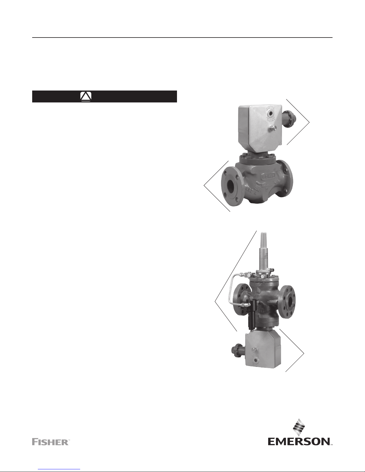
Type OS2 Slam-Shut Device
WARNING
!
Failure to follow these instructions or to
properly install and maintain this equipment
could result in an explosion and/or fire
causing property damage and personal injury
or death.
Fisher™ slam-shut devices must be installed,
operated and maintained in accordance
with federal, state and local codes, rules
and regulations and Emerson Process
Management Regulator Technologies,
Inc. instructions.
If the slam-shut device vents gas or a leak
develops in the system, service to the unit
may be required. Failure to correct trouble
could result in a hazardous condition.
Call a gas service person to service the
unit. Only a qualified person must install or
service the slam-shut devices.
TYPE E
VALVE
BODY
W8133
TYPE OSE
Type OS2
TYPE OS2
SLAM-SHUT
DEVICE
Introduction
Scope of the Manual
This instruction manual provides installation, maintenance
and parts ordering information for the Types OS2 and OSD2
slam-shut devices. The Type OS2 slam-shut device is used
on Type OSE with NPS 1 through 6 / DN 25 through 150
body sizes, while Type OSD2 is used on NPS 8 and 10 /
DN 200 and 250 body sizes.
For more information on Type OS2 installed on other
regulators such as Types EZHOSX, EZHSO-OSX,
EZLOSX and EZROSX, refer to the instruction manuals of
these products.
Description
Slam-shut devices are used to totally and rapidly cut off
gas flow when the inlet and/or outlet pressure in the system
either exceeds or drops below the setpoints. The Type OSE
consists of a valve, mechanism box (BM1 or BM2) and either
one or two modular sensing elements called manometric
devices (Type BMS1 or BMS2) (see Figure 2). All information
for the Type OSE (which includes a Type OS2 slam-shut
device and a Type E valve body) is contained in this
Instruction Manual.
TYPE EZR
REGULATOR
W8136
TYPE EZROSX
Figure 1. Type OS2 Slam-Shut Device on
Types OSE and EZROSX Constructions
TYPE OS2
SLAM-SHUT
DEVICE
North America Only
Page 2

Type OS2
Specifications
This section lists the specifications for the Type OS2 slam-shut valve. Factory specifications are stamped on the nameplate
fastened on the valve at the factory.
Body Sizes and End Connection Styles
Type OSE
WCC Steel
1 and 2 NPT; NPS 1, 2, 3, 4 and 6 /
DN 25, 50, 80, 100 and 150
CL150 RF, CL300 RF or CL600 RF
LCC Steel
NPS 8 and 10 / DN 200 and 250
CL150 RF, CL300 RF or CL600 RF
Cast Iron
1 and 2 NPT; NPS 1, 2, 3, 4 and 6 /
DN 25, 50, 80, 100 and 150
CL125 FF or CL250 RF
Types EZHOSX and EZHSO-OSX
LCC Steel
NPS 1, 2, 3 and 4 / DN 25, 50, 80 and 100
CL150 RF, CL300 RF or CL600 RF
Type EZLOSX
LCC Steel
NPS 2, 3 and 4 / DN 50, 80 and 100
CL150 RF, CL300 RF or CL600 RF
Type EZROSX
LCC Steel
NPS 1, 2, 3, 4 and 6 / DN 25, 50, 80, 100
and 150 CL150 RF, CL300 RF or CL600 RF
Maximum Inlet Pressure
(1)(2)
1470 psig / 101 bar or maximum body rating,
whichever is lower
Maximum Set Pressure
1470 psig / 101 bar or maximum body rating,
whichever is lower
Minimum Set Pressure
4.02 in. w.c. / 10 mbar
Outlet Pressure Ranges
See Table 2
Maximum Flowing Pressure Differential
BODY SIZE
NPS DN psig bar
1 25 360 24.8
2 50 360 24.8
3 80 360 24.8
4 100 150 10.3
6 150 85 5.9
8 200 119 8.2
10 250 67 4.6
MAXIMUM FLOWING
PRESSURE DIFFERENCE
(3)
Process Temperature Capabilities
(2)
-22 to 180°F / -30 to 82°C
Accuracy
+/-2.5% for set pressures at or below 1.45 psig / 0.1 bar
or +/-1% for set pressures above 1.45 psig / 0.1 bar,
+/-5% for the piston Types 27 and 17
Maximum Shutoff Pressure Differential
1470 psig / 101 bar or maximum body rating,
whichever is lower
Pressure Sensing Connections
1/4 NPT
Response Time
<1 second
Pressure Registration
External
Valve Plug Travel and Stem Diameter
BODY SIZE VALVE PLUG TRAVEL
NPS DN In. mm In. mm
1 25 1/2 13
2 50 1/2 13
3 80 1-1/8 29
4 100 2 51
6 150 2 51
8 200 2-3/4 70
10 250 3-1/4 82
VALVE PLUG STEM
DIAMETER
0.138 3.5
0.276 7.0
Approximate Weights
BODY SIZE APPROXIMATE WEIGHT
NPS DN lbs kg
1 25 36 16
2 50 70 32
3 80 121 55
(2)
4 100 216 98
6 150 445 202
8 200 785 356
10 250 1272 577
North America Only
Options
• Explosion-proof limit switch
• Additional manometric device for extra
pressure sensing
• Manual Push Button Trigger Switch
(4)
1. Relief pressure plus maximum allowable buildup over setting.
2. The pressure/temperature limits in this Instruction Manual or any applicable standard limitation should not be exceeded.
3.EndconnectionsforotherthanASMEstandardcanusuallybeprovided.ContactyourlocalSalesOfceforassistance.
4. The push button connects at the same Type BM2 port as a Type BMS2.
2
Page 3
Type OS2
BM2
(TYPES BMS1 AND BMS2)
TYPE BMS1
(RIGHT SIDE)
TYPE OS2
BM1
E0564
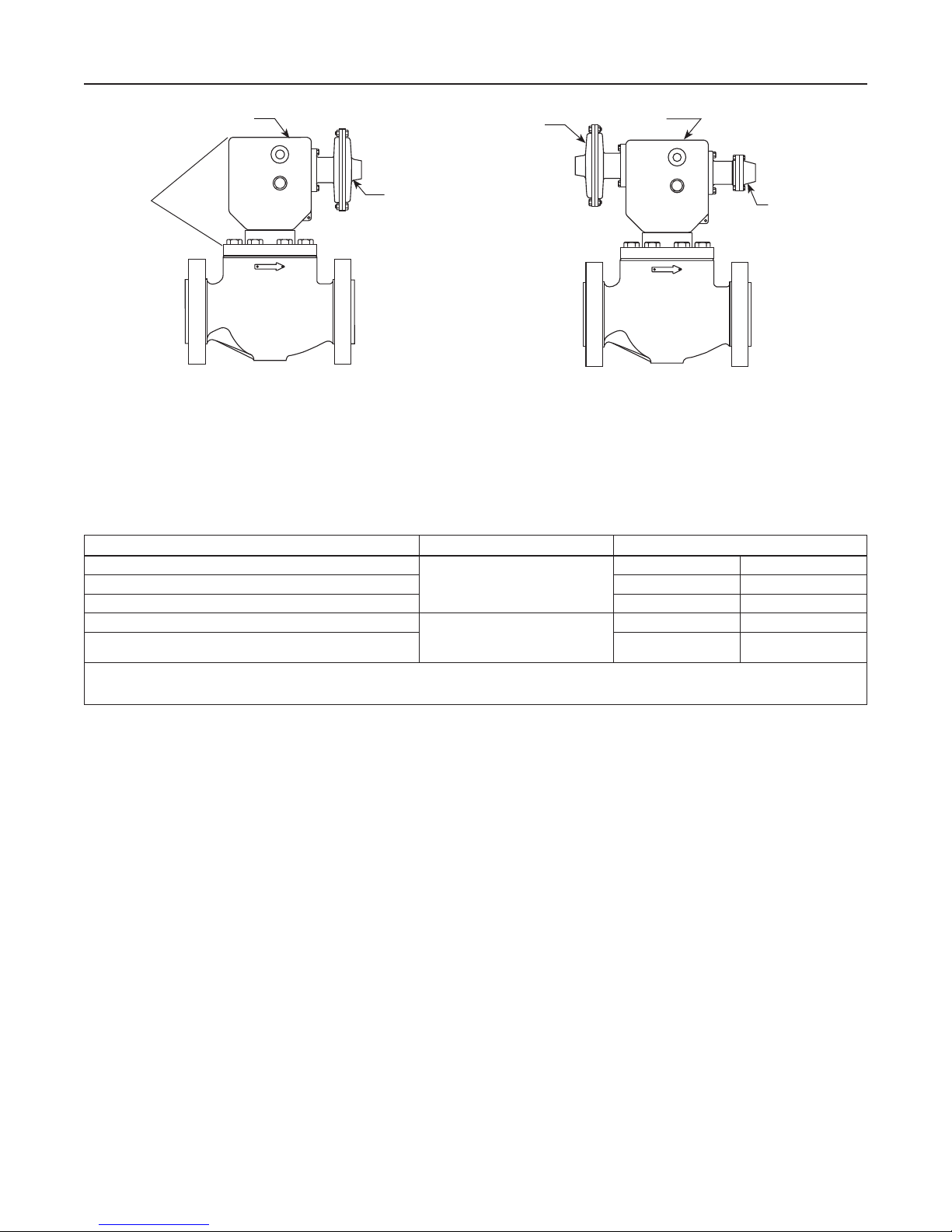
MECHANISM BOX (BM1) WITH 1 MANOMETRIC
SENSING DEVICE (TYPE BMS1)
TYPE BMS1
TYPE BMS2
(LEFT SIDE)
E0565
MECHANISM BOX (BM2) WITH 2 MANOMETRIC SENSING DEVICES
TOP-MOUNTED (STAND-ALONE TYPE OSE VALVE)
Figure 2. Types of Installation (Mounting on Horizontal Pipeline Only)
Table 1. Applications and Construction Guide (See Figure 2)
APPLICATION MECHANISM BOX REQUIRED MANOMETRIC SENSING DEVICE REQUIRED
Overpressure Shutoff (OPSO)
Underpressure Shutoff (UPSO) BMS1 - - - -
Overpressure Shutoff (OPSO) and Underpressure Shutoff (UPSO) BMS1
Overpressure Shutoff (OPSO) and Underpressure Shutoff (UPSO)
Overpressure Shutoff (OPSO), Overpressure Shutoff (OPSO) and
1. When using one manometric sensing device for both overpressure and underpressure shutoff, make sure that the difference between set pressures falls within the maximum range
shown in Table 2.
2. When using two manometric sensing devices (Types BMS1 and BMS2), the Type BMS1 can only be used for high trip.
Underpressure Shutoff (UPSO)
BM1
BM2
BMS1 - - - -
BMS1
BMS1
(1)
(2)
(2)
- - - -
BMS2
BMS2
(1)
North America Only
Type EZROSX (see Figure 1) is a combination of the
Type EZR regulator and the Type OS2 slam-shut device.
For installation, maintenance and parts information on
the Type EZR portion, refer to Type EZR Instruction
Manual D102600X012.
Type EZHOSX is a combination of the Type EZH regulator
and the Type OS2 slam-shut device. Details related to
installation, maintenance and parts information are listed in
the Type EZH Instruction Manual D103077X012.
Type EZLOSX is a combination of the Type EZL regulator
and the Type OS2 slam-shut device. Details related to
installation, maintenance and parts information are listed in
the Type EZL Instruction Manual D103091X012.
Incorporated in the Type OS2 (up to NPS 6 / DN 150 body
size) valve plug is an automatic internal bypass valve
mechanism, which balances pressures on both sides of the
plug when resetting. Type OSD2 will be used for NPS 8 and
10 / DN 200 and 250 Type OSE slam-shut valves; in this
case the bypass is not internal but external.
The Types OS2 and OSD2 slam-shut devices can be used
for all pressure ranges from 4.02 in. w.c. to 1470 psig /
10 mbar to 101 bar by simply replacing the manometric
sensing device. The Type OS2 can be configured for
OverPressure ShutOff (OPSO), UnderPressure ShutOff
(UPSO), OverPressure Shutoff and UnderPressure ShutOff
(OPSO/UPSO), manual shutoff or remote shutoff.
Mechanism Box (BM1 or BM2)
The mechanism box (BM1 or BM2, see Figure 2) is designed
to close the slam-shut valve. The detection of pressure
variances is sensed by a double-stage trip mechanism (see
Figure 7). The first stage is the detection stage and will only
trip when the system pressure reaches the set pressure of
the manometric sensing device. The second stage is the
power stage and once tripped by the first stage, the closing
spring causes the valve plug to slam-shut and remain
closed until the valve is manually reset. If there are any inlet
pressure variances or vibrations subjected to the second
stage components, they are not transmitted to the first stage
trip mechanism. This unique double-stage trip mechanism
virtually eliminates nuisance tripping commonly found in
other shutoff devices.
3
Page 4

Type OS2
Table 2. Spring Ranges, Part Numbers and Maximum and Minimum Pressures for the Manometric Sensing Devices (Types BMS1 and BMS2)
SPRING RANGE
4.02 to 14.1 in. w.c. /
10 to 35 mbar
9.97 to 33.2 in. w.c. /
25 to 83 mbar
18 in. w.c. to 2.0 psig /
45 mbar to 0.14 bar
1.0 to 3.5 psig /
70 mbar to 0.24 bar
1.7 to 5.6 psig /
0.12 to 0.39 bar
2 to 11 psig /
0.14 to 0.76 bar
4 to 19 psig / 0.28 to 1.3 bar Brown FA113202X12 1.16 / 80 mbar 8.70 / 0.60
7 to 33 psig / 0.48 to 2.3 bar Black FA114139X12 2.47 / 0.17 16.0 / 1.1
15 to 75 psig / 1.0 to 5.2 bar Blue FA113200X12
31 to 161 psig / 2.1 to 11.1 bar Brown FA113202X12 10.2 / 0.70 79.8 / 5.5
59 to 235 psig / 4.1 to 16.2 bar Black FA114139X12 23.2 / 1.6 145 / 10.0
235 to 323 psig / 16.2 to 22.3 bar Brown FA113202X12
323 to 588 psig / 22.3 to 40.5 bar Black FA114139X12 94.3 / 6.5
588 to 808 psig / 40.5 to 55.7 bar Brown FA113202X12
808 to 1470 psig / 55.7 to 101 bar Black FA114139X12 174 / 12.0
81 to 323 psig / 5.60 to 22.3 bar Brown FA113202X12
122 to 514 psig / 8.41 to 35.4 bar Black FA114139X12 36.3 / 2.5 290 / 20.0
257 to 1058 psig / 17.7 to 73.0 bar Gray FA113201X12 315 1058 / 73.0 72.5 / 5.0 479 / 33.0
1. Minimum suggested difference between slam-shut set pressure and normal operating pressure of the system.
2. Maximum difference between overpressure and underpressure when using one manometric device (Type BMS1) with tripping hook (see Figure 5). For underpressure and overpressure
points greater than this maximum number, use a second manometric device (Type BMS2) for underpressure protection.
SPRING
COLOR
Purple FA113195X12
Orange FA113196X12
Red FA113197X12
Yellow FA113198X12
Green FA113199X12
Gray FA113201X12
SPRING PART
NUMBER
MANOMETRIC
SENSING
DEVICE TYPE
162
71 235 / 16.2
27
17 1470 / 101
236
MANOMETRIC
SENSING
DEVICE STYLE
Diaphragm
Piston
Bellows
MAXIMUM
SENSING INLET
PRESSURE,
psig / bar
74 / 5.1
1470 / 101
514 / 35.4
SETPOINT
TOLERANCE,
psig / bar
1.61 in. w.c. /
4 mbar
2.02 in. w.c. /
5 mbar
4.02 in. w.c. /
10 mbar
5.62 in. w.c. /
14 mbar
7.23 in. w.c. /
18 mbar
20.1 in. w.c. /
50 mbar
5.08 / 0.35 36.3 / 2.5
43.5 / 3.0
102 / 7.0
14.5 / 1.00 145 / 10.0
MAXIMUM DIFFERENCE
OVERPRESSURE AND
(1)
UNDERPRESSURE,
BETWEEN
(2)
psig / bar
4.02 in. w.c. /
10 mbar
10 in. w.c. /
25 mbar
20.1 in. w.c. /
50 mbar
24.1 in. w.c. /
60 mbar
2.18 / 0.15
5.08 / 0.35
Requires use
of Type BMS1
or BMS2
Manometric Sensing Device (Type BMS1
or BMS2) (See Figure 2)
Pressure from the system is sensed through control lines
into the manometric sensing device (Type BMS1, BMS2 or
Types BMS1 and BMS2). Depending on the configuration,
the Type BMS1 or BMS2 will transmit these pressure
fluctuations to the mechanism box. If these fluctuations
reach the setpoint of the manometric sensing device
(Type BMS1 or BMS2), the device will activate the tripping
mechanism in the mechanism box (Type BM1 or BM2) and
cause the valve to slam-shut.
Remote Shutoff
Remote Tripping is accomplished using a 3-way solenoid
valve installed in the control line of a Type BMS1 or
BMS2 manometric device configured for underpressure
protection (UPSO) or overpressure and underpressure
protection (OPSO/UPSO). When de-energized, the solenoid
valve allows the Type BMS manometric device to monitor
the controlled pressure as if the solenoid valve was not
present. When energized, the solenoid valve will be
repositioned to connect the Type BMS manometric device to
atmospheric pressure tripping the underpressure protection
slam-shut setting.
*For further instructions on Types EZR, EZH and EZL, refer to the corresponding instruction manual of these products.
Principle of Operation* (See Figure 3)
The Type OSE slam-shut valve and the Type OS2 slam-shut
device used on Type EZHOSX, EZROSX or EZLOSX
provides overpressure and/or underpressure protection
by shutting off the flow to the downstream system. The
slam-shut valve is typically installed upstream of a pressure
reducing regulator as shown in Figure 4.
Pressure is registered on one side of the diaphragm, piston
or bellows and is opposed by the setpoint control spring of
the manometric sensing device. The Type OS2 slam-shut
device tripping pressure is determined by the setting of the
control spring.
Overpressure: when the sensed pressure increases
above the setpoint, the pressure on top of the diaphragm
overcomes the spring setting and moves the manometric
device stem.
Underpressure: when the sensed pressure decreases
below the setpoint, the control spring pressure below the
diaphragm overcomes the downstream pressure and pushes
the diaphragm which moves the manometric device stem.
When the sensed pressure rises above the set pressure (or
drops below the set pressure) the manometric device senses
the pressure change and triggers the detection stage which
North America Only
4
Page 5
TYPE
EVENT
50 mm
35 mm
15 mm
COURSE CLAPET
2
R
U
N
S
T
A
R
T
4
6
8
E0559
PRX
S
L
A
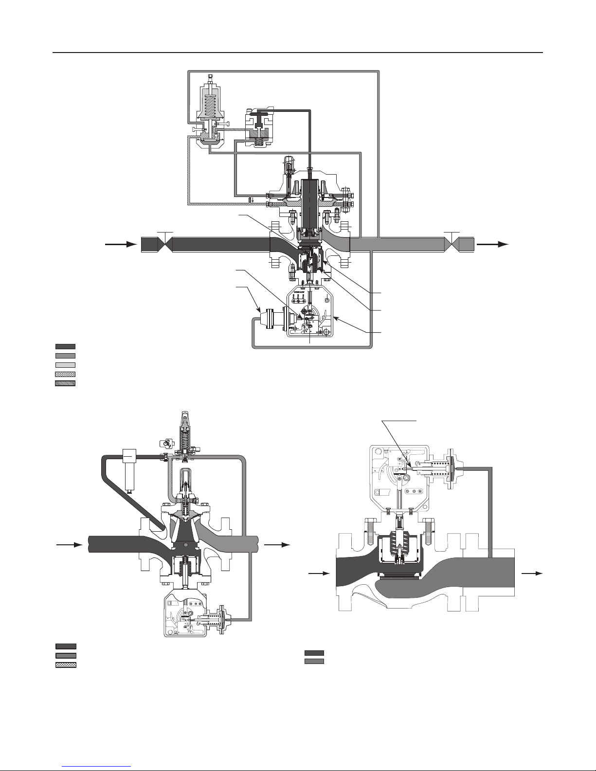
EQUALIZER BYPASS
MANOMETRIC DEVICE STEM
Type OS2
TYPE
SA/2
R
B
V
M
E0939
INLET PRESSURE
OUTLET PRESSURE
ATMOSPHERIC PRESSURE
LOADING PRESSURE
PILOT SUPPLY PRESSURE
MANOMETRIC DEVICE
R
U
N
2
4
6
S
T
8
A
R
T
TYPE EZHOSX
COURSE CLAPET
50 mm
35 mm
15 mm
VALVE PLUG
VALVE PLUG DISK
EVENT
MECHANISM BOX
MANOMETRIC DEVICE STEM
North America Only
E0559
INLET PRESSURE
OUTLET PRESSURE
LOADING PRESSURE
TYPE EZROSX TYPE OSE
E0558
INLET PRESSURE
OUTLET PRESSURE
Figure 3. Operational Schematics
5
Page 6
Type OS2
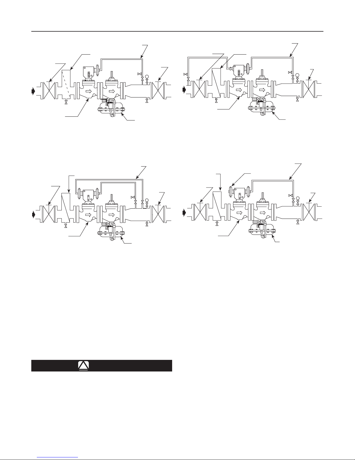
UPSTREAM
BLOCK VALVE
TYPE OSE
SLAM-SHUT VALVE
E0560
OVERPRESSURE AND UNDERPRESSURE SHUTOFF
UPSTREAM
BLOCK
VALV E
DOWNSTREAM SENSING LINE
OPTIONAL STRAINER
USING ONE MANOMETRIC DEVICE
DOWNSTREAM SENSING LINE
OPTIONAL STRAINER
BLOCK
VALV E
PRESSURE
REGULATOR
BLOCK
VALV E
UPSTREAM
BLOCK VALVE
TYPE OSE
SLAM-SHUT VALVE
E0561
OPTIONAL
STRAINER
UPSTREAM
BLOCK
VALV E
DOWNSTREAM SENSING LINE
OPTIONAL STRAINER
MINIMUM/MAXIMUM UPSTREAM AND
DOWNSTREAM PRESSURE
DOWNSTREAM SENSING LINE
EXTERNAL TRIP
PRESSURE
BLOCK
VALV E
PRESSURE
REGULATOR
BLOCK
VALV E
TYPE OSE
SLAM-SHUT VALVE
E0562
OVERPRESSURE AND UNDERPRESSURE SHUTOFF
USING TWO MANOMETRIC DEVICES
PRESSURE
REGULATOR
Figure 4. Typical Installations
activates the second stage, releasing the slam-shut valve
plug. A tight and total shutoff is ensured by the plug seal
O-ring closing on the orifice and is helped by the “dash pot”
effect between the bonnet skirt and the valve plug. A “dash
pot” effect occurs when the valve plug closes by having both
the closing spring and the inlet pressure pushing on top of
the valve plug. This is accomplished by ports around the skirt
of the bonnet allowing inlet pressure above the valve plug.
Installation*
WARNING
!
Personal injury, equipment damage or
leakage due to escaping gas or bursting
of pressure-containing parts may result
if the slam-shut valve is installed where
its capabilities can be exceeded or where
TYPE OSE
SLAM-SHUT VALVE
E0563
EXTERNAL SIGNAL
PRESSURE
REGULATOR
conditions exceed any ratings of the adjacent
piping or piping connections. To avoid this,
install the slam-shut valve where service
conditions are within unit capabilities and
applicable codes, regulations or standards.
Additionally, physical damage to the
slam-shut valve could break the mechanism
box off the main valve, causing personal
injury and property damage due to escaping
gas. To avoid such injury or damage, install
the unit in a safe location.
Installation, operation and maintenance
procedures performed by unqualified
personnel may result in improper adjustment
and unsafe operation. Either condition may
result in equipment damage or personal
injury. Use qualified personnel when
installing, operating and maintaining the unit.
North America Only
*For further instructions on Types EZR, EZH and EZL, refer to the corresponding instruction manual of these products.
6
Page 7

Type OS2
Table 3. Main Valve Body Sizes, End Connection Styles and Body Pressure Ratings
MAIN VALVE BODY SIZE
NPS DN psig bar
1
2
3
4
6
1
2
3
4
6
8
10
1.RatingsandendconnectionsforotherthanASMEstandardcanusuallybeprovided.ContactyourlocalSalesOfceforassistance.
2.SeeSpecicationsandTable2foradditionalpressureratings.
3. Available with NPS 1 and 2 / DN 25 and 50 only.
25
50
80
100
150
25
50
80
100
150
200
250
MAIN VALVE BODY MATERIAL END CONNECTION STYLE
(3)
NPT
Cast iron
WCC Steel
LCC Steel
CL125 FF 200 13.8
CL250 RF 500 34.5
(3)
NPT
CL150 RF 290 20.0
CL300 RF 750 51.7
CL600 RF 1500 103
CL150 RF 290 20.0
CL300 RF 750 51.7
CL600 RF 1500 103
(1)
STRUCTURAL DESIGN RATING
400 27.6
1500 103
(2)
Clean out all pipelines before installation and check to be
sure the valve has not been damaged or collected foreign
material during shipment. Use suitable line gaskets and
good bolting practices with a flanged body. The Type OSE
must be installed in a horizontal position with the mechanism
box above the body (see Figure 2). The Types EZHOSX,
EZROSX and EZLOSX are installed with the mechanism
box typically below the pipe. Type OS2 slam-shut device can
also be installed in a pit that is subject to flooding by venting
the mechanism box above the maximum possible flood
level. When used below ground, the vent must be relocated
(piped) to keep the mechanism box from collecting moisture
and/or other foreign material. Install obstruction-free tubing
or piping into the 1/4 NPT vent tapping. Provide protection
on the relocated vent by installing a screened vent cap into
the end of the vent pipe.
Type OS2 can be used along with a token relief valve to
minimize unnecessary shutoff. The relief valve is set to
open before the Type OS2 slam-shut device activates.
This arrangement allows the relief valve to handle minor
overpressure problems such as gas thermal expansion or
seat leakage due to dirt moving through the system which
may move out of the regulator during the next operating
cycle. The slam-shut device does activate if the regulator
has a major malfunction with excessive gas flow that
exceeds the token relief capacity.
The manometric device requires an external sensing line
which should be tapped into a straight run of pipe 8 to
10 pipe diameters downstream or upstream of the slam-shut
device. If impossible to comply with this recommendation
due to the pipe arrangement, it may be better to position
the sensing line tap nearer the regulator or slam-shut outlet
rather than downstream of a block valve. Do not position
the tap near any elbow, swage or nipple which might cause
turbulence. It is recommended to install an isolation valve
and a vent valve on the sensing line, which can be useful for
tripping and verifications.
Startup*
WARNING
!
To avoid personal injury or property
damage due to explosion or damage to
regulator or downstream components during
startup, release downstream pressure to
prevent an overpressure condition on the
diaphragm of the regulator. In order to avoid
an overpressure condition and possible
equipment damage, pressure gauges
should always be used to monitor pressures
during startup.
These startup procedures are for the Type OSE/OS2 only.
1. Make sure the upstream and downstream shutoff valves
are closed.
2. Slowly open the upstream shutoff valve.
3. For NPS 8 and 10 / DN 200 and 250 body sizes, slowly
open the bypass valve.
4. The slam-shut valve is shipped with the slam-shut
device in the tripped position. To reset the slam-shut,
follow the procedure under Resetting the Trip
Mechanism in the Adjustment section.
5. For NPS 8 and 10 / DN 200 and 250 body sizes, close
the slam-shut valve bypass.
6. Slowly open the downstream shutoff valve.
7. Check all connections for leaks.
8. Adjust the slam-shut pressure setting by following the
appropriate procedures in the Adjustment section.
North America Only
*For further instructions on Types EZR, EZH and EZL, refer to the corresponding instruction manual of these products.
7
Page 8

Type OS2
Adjustment
Typically, adjustments are carried out with the slam-shut
valve closed. Only the detection stage is reset (see Figure 7
and the section on Resetting the Tripping Mechanism).
Follow the procedures below for setpoint adjustment and use
the resetting tool (see Figure 8) to move the adjusting screw.
CAUTION
Before any adjustment, check that the
spring range installed corresponds to the
required setpoint.
CAUTION
Before beginning adjustment procedures, be
sure there is no pressure in the manometric
sensing device (Type BMS1 or BMS2).
Type BMS1 (Figure 5)
Overpressure Shutoff Only
Adjusting the Threaded Stem:
1. Remove the tripping hook or rotate so it cannot contact
Pin D2.
2. Turn in the adjusting screw until the distance between
the threaded stem and Pin D1 stops increasing.
3. Reset the detection stage only. (See Figure 7 and the
section on Resetting the Trip Mechanism.)
4. Adjust the threaded stem to a distance of 1/16 in. /
1.6 mm from Pin D1 (detection stage set).
5. Tighten threaded stem locknut.
Adjusting the Overpressure Trip Point:
1. Pressurize the Type BMS1 to the desired trip pressure.
2. Turn in the adjusting screw until the detection stage can
be reset.
3. Turn out the adjusting screw until the detection
stage trips.
4. Verify that the trip pressure is equal to the desired
pressure setting by reducing pressure to the
Type BMS1, resetting the detection stage and then
increasing pressure to the Type BMS1 until the detection
stage trips. Adjust trip pressure setting if necessary.
5. Tighten adjusting screw locknut.
Underpressure Shutoff Only
Adjusting the Threaded Stem and Tripping Hook:
1. Rotate the tripping hook so that it cannot contact Pin D2.
2. Turn out the adjusting screw.
3. Pressurize the Type BMS1 to the desired trip pressure.
ADJUSTING SCREW
LOCKNUT
ADJUSTING
SCREW
TRIPPING HOOK
LOCKNUTS
E0606
TRIPPING HOOK
PIN D2
TRIPPING
PLATE
PIN D1
Figure 5. Type BMS1 Construction
THREADED
STEM
THREADED STEM
LOCKNUT
OVERPRESSURE SHUTOFF
4. Reset the detection stage only. (See Figure 7 and the
section on Resetting the Trip Mechanism)
5. Adjust the threaded stem to a distance of
1/16 in. / 1.6 mm from Pin D1 (detection stage set).
6. Tighten threaded stem locknut.
7. Rotate the tripping hook into position and adjust the
tripping hook locknuts until the hook is at a distance of
1/16 in. / 1.6 mm from Pin D2.
8. Tighten tripping hook locknuts.
Adjusting the Underpressure Trip Point:
1. Maintain the desired trip pressure in Type BMS1.
2. Turn in the adjusting screw until the detection stage
is tripped.
3. Verify that the trip pressure is equal to the desired
pressure setting by increasing pressure to the
Type BMS1, resetting the detection stage and then
reducing pressure to the Type BMS1 until the detection
stage trips. Adjust trip pressure setting if necessary.
4. Tighten adjusting screw locknut.
Overpressure and Underpressure Shutoff
Adjusting the Threaded Stem:
1. Rotate the tripping hook so that it cannot contact Pin D2.
2. Turn out the adjusting screw.
3. Pressurize the Type BMS1 to the desired overpressure
trip pressure.
4. Reset the detection stage only. (See Figure 7 and the
section on Resetting the Trip Mechanism.)
5. Adjust the threaded stem until it just touches Pin D1.
6. Manually trip the detection stage by moving Pin D1.
7. Unscrew the threaded stem two turns which is a
distance of approximately 1/16 in. / 1.6 mm.
8. Tighten threaded stem locknut.
North America Only
8
Page 9

Type OS2
Adjusting the Overpressure Trip Point:
Same procedure as overpressure shutoff only.
Adjusting the Underpressure Trip Point:
1. Pressurize the Type BMS1 to a pressure between the
desired overpressure and underpressure trip points.
2. Reset the detection stage only. (See Figure 7 and the
section on Resetting the Trip Mechanism.)
3. Pressurize the Type BMS1 to the desired underpressure
trip pressure.
4. Adjust the hook by progressively moving the tripping
hook locknuts until the detection stage trips.
5. Tighten tripping hook locknuts.
6. Verify that the trip pressure is equal to the desired
pressure setting by increasing pressure to the
Type BMS1, resetting the detection stage and then
reducing pressure to the Type BMS1 until the detection
stage trips. Adjust trip pressure setting if necessary.
Type BMS2 (Figure 6)
Overpressure Shutoff Only
Adjusting the Overpressure Push Button:
1. Remove the tripping hook.
CAUTION
Be sure there is no pressure in the
manometric sensing device before doing the
following steps.
2. Turn in the adjusting screw until the distance between
the threaded stem and Pin D2 stops increasing.
3. Reset the detection stage only. (See Figure 7 and the
section on Resetting the Trip Mechanism.)
4. Adjust the push button to a distance of 1/16 in. / 1.6 mm
from Pin D2.
5. Tighten push button locknut.
Adjusting the Overpressure Trip Point:
Same procedure as adjusting the Type BMS1 for overpressure
shutoff only.
ADJUSTING
SCREW
ADJUSTING SCREW
LOCKNUT
E0607
OVERPRESSURE AND UNDERPRESSURE SHUTOFF
TRIPPING
HOOK
LOCKNUT
Figure 6. Type BMS2 Construction
PUSH BUTTON LOCKNUT
PUSH BUTTON
PIN D2
TRIPPING
PLATE
PIN D1
TRIPPING
HOOK
THREADED
STEM
THREADED
STEM
LOCKNUT
5. Adjust the tripping hook to a distance of 1/16 in. /
1.6 mm from Pin D1.
6. Tighten tripping hook locknut.
Adjusting the Underpressure Trip Point:
Same procedure as adjusting the Type BMS1 for
underpressure shutoff only.
Overpressure and Underpressure Shutoff
Adjusting the Push Button:
1. Remove the tripping hook.
2. Turn out the adjusting screw.
3. Pressurize the Type BMS2 to the overpressure shutoff
trip pressure.
4. Reset the detection stage only. (See Figure 7 and the
section on Resetting the Trip Mechanism.)
5. Adjust the push button until it just touches Pin D2.
6. Manually trip the detection stage by moving Pin D2
(see Figure 5).
7. Unscrew the push button two turns which is a distance
of approximately of 1/16 in. / 1.6 mm.
8. Tighten push button locknut.
Adjusting the Overpressure Trip Point:
Same procedure as overpressure shutoff only.
North America Only
Underpressure Shutoff Only
Adjusting the Underpressure Tripping Hook:
1. Remove the overpressure push button or move it so that
it cannot contact Pin D2.
2. Turn out the adjusting screw.
3. Pressurize the Type BMS2 to the desired underpressure
trip pressure.
4. Reset the detection stage only. (See Figure 7 and the
section on Resetting the Trip Mechanism.)
Adjusting the Underpressure Trip Point:
1. Pressurize the Type BMS2 to a pressure between the
desired overpressure and underpressure trip points.
2. Reset the detection stage only. (See Figure 7 and the
section on Resetting the Trip Mechanism.)
3. Pressurize the Type BMS2 to the desired underpressure
trip pressure.
4. Turn in the tripping hook until the detection stage trips.
5. Tighten tripping hook locknut.
9
Page 10

Type OS2
D2
SLIDING
CLEVIS
D1
SECOND
STAGE
RELEASING
SHAFT
TRAVEL STOP
RESET PIN WITH WHITE DOT
TRAVEL STOP
E0611
VALVE OPEN
SLAM-SHUT VALVE OPEN
STEP A
TRAVEL STOP
VALVE CLOSED
E0612
STEP B
VALVE CLOSED
SLAM-SHUT VALVE CLOSED
RESETTING
TOOL
TRAVEL STOP
VALVE OPEN
North America Only
E0613
RESET DETECTION STAGE (FIRST STAGE)
NOTE: ORIENTATION SHOWN IS FOR TYPE OSE. ORIENTATION FOR TYPES EZHOSX, EZROSX AND EZLOSX IS ROTATED 180°.
10
E0614
RESET POWER STAGE (SECOND STAGE)
Figure 7. Mechanism Trip Stages
Page 11

Type OS2
6. Verify that the trip pressure is equal to the desired
pressure setting by increasing pressure to the
Type BMS2, resetting the detection stage and then
reducing pressure to the Type BMS2 until the detection
stage trips. Adjust trip pressure setting if necessary.
Resetting the Trip Mechanism
Resetting of the Type OS2 slam-shut device is done
manually and, for NPS 8 and 10 / DN 200 and 250 body
sizes, with the bypass valve open. After the Type OS2 has
closed, it must be manually reset before it can be placed
back in service. Before resetting the Type OS2, check for
and correct the reason for the overpressure/underpressure
condition. For the following procedures, see Figures 7 and 8.
Note
To reset the detection stage, the pressure
in the manometric sensing device must
be below the overpressure trip point and/
or above the underpressure trip point.
Otherwise the detection stage cannot
be reset.
Note
Because the Type OS2 mounted on the
Type EZHOSX, EZROSX or EZLOSX is turned
180°, the following directions apply to the
Type OSE only, however, the reset procedure
for the Type EZHOSX, EZROSX or EZLOSX is
the same. When a specific direction is given
(i.e. top left), the Type EZHOSX, EZROSX
or EZLOSX direction will be reversed
(i.e. bottom right).
To reset the Type OS2, close the upstream block valve.
Open the front cover of the mechanism box.
Detection Stage (First Stage)
The reset pin with white dot is at the top center location of
the mechanism box, see Figure 8. Push this pin up and to
the right (Type OSE only, see note above). This action will
lock in the detection stage (see step A in Figure 7).
When movement is started on the stem, the internal bypass
in sizes from NPS 1 through 6 / DN 25 through 150 will open
and equalize the pressure on each side of the valve plug
before the valve plug can be moved off the seat. For NPS 8
and 10 / DN 200 and 250, external bypass valve should be
opened. Continue turning the reset tool.
CAUTION
Wait for the pressure on each side of the
valve plug to equalize before proceeding to
the following steps. Never use an extension
with the reset tool when resetting the
second stage. Failure to do so may result in
equipment damage.
This action will raise the valve plug, compress the closing
spring and latch the second stage (power stage) mechanism.
Replace the reset tool on its holder and replace the cover.
Slowly open the upstream block valve.
Shutdown*
WARNING
!
To avoid personal injury or property damage
due to explosion or damage to shutoff
device, regulator or downstream components
during shutdown, release downstream
pressure to prevent an overpressure
condition on the regulator diaphragm.
Installation arrangements may vary, but in any installation it
is important that the valves be opened or closed slowly. The
steps below apply to the typical installation.
1. Slowly close the downstream shutoff valve.
2. Slowly close the upstream shutoff valve.
3. Slowly open the vent valves downstream of the
slam-shut valve.
4. Slowly open the vent valves upstream of the
slam-shut valve.
North America Only
Power Stage (Second Stage)
Note
The reset tool is keyed and will only fit on
the second stage releasing shaft in one
orientation. Be sure the tool securely fits
onto the shaft before turning.
To reset the power stage, use the square reset tool located
on the lower left corner of the mechanism box. Place the
square end of the tool on the second stage releasing shaft at
the center of the box and slowly rotate clockwise (see step B
in Figure 7).
*For further instructions on Types EZR, EZH and EZL, refer to the corresponding instruction manual of these products.
Maintenance
Instructions are given for complete disassembly and
assembly. Key numbers are referenced in Figure 14 for
NPS 1 through 6 / DN 25 through 150 body sizes and
Figure 15 for NPS 8 and 10 / DN 200 and 250 body sizes
unless otherwise noted.
11
Page 12

Type OS2
Mechanism Box (BM1 or BM2)
Disassembly for NPS 1 through 6 / DN 25 through
150 Body Sizes (Refer to Figure 14)
WARNING
!
Avoid personal injury or damage to
property from sudden release of pressure
or uncontrolled gas or other process fluid.
Before disassembling, carefully relieve
all pressures. Use gauges to monitor
inlet and outlet pressures while releasing
these pressures.
Note
The only parts that are replaceable on
the Type OS2 are the equalizer bypass
component, manometric sensing device
(Types BMS1 and BMS2) and the sealing
components. The seat ring on the Type OSE
is pressed into the body and is not
field removable.
Note
The position of the travel stop (Figure 13)
depends on the Type of assembly and
body size. The travel stop must be in the B
position (Figure 13) for NPS 1 and 2 / DN 25
and 50 body sizes. For all other body sizes,
the travel stop must be in the C position
(Figure 13).
The cover is held on by one screw which can be unscrewed
manually or by using a socket (maximum recommended
torqueis1.8ft-lbs/2.4N•m).
1. Open the mechanism cover and replace the cover screw
O-ring by removing the circlip.
CAUTION
Trip the mechanism if it is not already
released by moving Pin D1 (see Figure 7) to
remove as much spring tension on the stem
as possible.
2. Trip the mechanism by carefully turning the tripping
plate (Pins D1 and D2) clockwise (refer to Figures 5
and 6).
3. Remove the clip (refer to Figure 8). Turn and detach
the clevis from the stem by pulling the pin from the
sliding clevis.
4. Remove the two cap screws (key 39) holding the
mechanism box (key 16) to the bonnet (key 15) and
remove the mechanism box.
5. Remove the nuts (key 23, for NPS 4 and 6 / DN 100
and 150 only) or cap screws (key 21) holding the bonnet
(key 15) to the body (key 1).
6. The bonnet (key 15), valve plug (key 5H) (with equalizer
bypass, key 5A in NPS 1 through 6 / DN 25 through
150 body sizes), main spring (key 12) and small stem
bushing (key 24) will lift out of the body as a unit. Set the
unit on a hard flat surface with the valve plug (key 5H)
at the bottom and press down on the bonnet (key 15) to
compress the main spring (key 12), allowing the stem to
be unhooked from the coupling head.
7. Use a spanner wrench (a wrench is supplied with one
of the replacement parts kits) to unscrew the equalizer
bypass (key 5A) from the valve plug (key 5H) (refer
to Figures 10 and 11). The NPS 1 / DN 25 body size
equalizer bypass (key 5A) holds the plug O-ring (key 32)
to the valve plug (key 5H). On the NPS 2 and 3 / DN 50
and 80 body sizes, the equalizer bypass (key 5A) holds
the plug disk and the plug O-ring (key 32) to the valve
plug (key 5H). The NPS 4 and 6 / DN 100 and 150 body
sizes valve plug disk and valve plug are held together
by six cap screws. On these body sizes, remove the cap
screws and valve plug disk to replace the plug O-ring
(refer to Figure 11).
Note
The equalizer bypass (key 5A) is a common
part between valve plug sizes from NPS 1
through 6 / DN 25 through 150 body sizes.
The equalizer bypass (key 5A) is not
serviceable and must be replaced as a unit.
8. To remove the equalizer bypass (key 5A) from
the coupling and coupling head, drive out the roll
Pin (key 5C) on the coupling (refer to Figure 10).
Disassembly for NPS 8 and 10 / DN 200 and 250
Body Sizes (Refer to Figures 13 and 15)
1. Remove the mechanism box (BM) cover (key 96).
2. Remove the travel stop (see Figure 13).
3. Unscrew the nuts (keys 97 and 98).
4. Remove the resetting latch (key 100).
5. Remove the bolt (key 113) and the spacer (key 114).
6. Remove the cam (key 121) and yoke (key 108).
7. Unscrew the two screws (key 117).
8. Retain the square nut (key 53) situated at the extremity
of the stem valve (key 20).
North America Only
12
Page 13

MECHANISM BOX
(BM, KEY 16)
CLIP
SLIDING CLEVIS
STEM
SCREW (KEY 39) AND
FLAT WASHER (KEY 40)
W8128A
LOCATION FOR
SWITCH (KEY 27)
RESET PIN WITH WHITE DOT
Figure 8. Type OS2 Internal Parts
Type OS2
TRIPPING PLATE
MANOMETRIC SENSING
DEVICE (TYPE BMS1, KEY 17)
MANOMETRIC DEVICE
THREADED STEM
SECOND STAGE RELEASING SHAFT
TRAVEL STOP
RESETTING TOOL
(KEY 3)
CAP SCREW
(KEY 21)
BONNET (KEY 15)
9. Unscrew the cap screws (key 21).
10. Remove the O-ring (key 11).
11. For NPS 8 / DN 200, insert a spacer (key 114) between
the cam (key 121) and square nut (key 53) or a stack
washer (key 99) between the bolt (key 113) and square
nut (key 53).
12. Remove the bonnet (key 15) / valve plug assembly
(key 13).
Disassembly of the Valve Plug (if required) (Refer
to Figure 15)
1. Remove the square nut (key 53).
2. Remove the small stem bushing (key 24).
3. Extract the bonnet (key 15) / valve cylinder (key 14).
Note
Normally, the bonnet (key 15) / valve cylinder
(key 14) part cannot be dismantled.
4. Remove the main spring (key 12).
5. Remove the screws (key 36) and fixing O-ring (key 34)
while the pin (key 35) remains mounted on the valve
plug body (key 13A).
Disassembly of the Valve Plug O-ring
(if required) (Refer to Figure 15)
1. The valve plug body (key 13A) is threaded to the
valve plug cylinder (key 13B), the O-ring (key 34) can
be reached by unscrewing the valve plug assembly
(keys 13A and 13B) using a bar of 800 and 4 screws
[2 M8 on valve plug cylinder (key 13B) and 2 M10 on
valve plug body (key 13A)].
Assembly for NPS 1 through 6 / DN 25 through
150 Body Sizes (Refer to Figure 14)
1. Attach a new equalizer bypass (key 5A) to the coupling
using a roll pin (key 5C, refer to Figure 10).
2. Screw the equalizer bypass (key 5A) into the valve
plug (key 5H) with the plug disk and a new plug O-ring
(key 32, Figure 11). Be careful not to nick or pinch the
O-ring (key 32) when tightening the equalizer bypass
(key 5A). On the NPS 4 and 6 / DN 100 and 150 body
sizes, attach the plug disk and a new plug O-ring
(key 32) to the valve plug (key 5H) using six cap screws
(refer to Figures 11 and 15).
3. Replace the valve piston ring (key 7) on the inside of the
bonnet skirt.
4. Refer to Figures 14 and 16. Place a new O-ring
(included in key 24) on the small stem bushing (key 24).
Set the valve plug assembly (key 5) on a hard flat
surface. Set the main spring (key 12) in place on the
valve plug (key 5H). Place the bonnet (key 15) on the
spring (key 12) and compress the spring by pressing
down on the bonnet. Attach the stem (key 24) to the
coupling head of the valve plug (key 5H) through the
bonnet (key 15). Slowly release the bonnet (key 15) to
allow the spring tension to seat the small stem bushing
(key 24) onto the bonnet and carefully place the O-ring
(key 1C).
5. Place the bonnet assembly (key 15) onto the body
(key 1) using a new O-ring (key 10) and a new
external O-ring (key 11). Secure the bonnet (key 15)
by tightening down the nuts (key 23, for NPS 4 and 6 /
DN 100 and 150 only) or cap screws (key 21).
North America Only
13
Page 14

Type OS2
COUPLING
COUPLING
HEAD
EQUALIZER BYPASS
(KEY 5A)
ROLL PINS
W6853_1
Figure 9. Equalizer Bypass and Coupling Assembly for
NPS 1 through 6 / DN 25 through 150 Body Sizes
6. Place the mechanism box (key 16) onto the bonnet
(key 15) and attach using two cap screws (key 39) and
two flat washers (key 40).
7. Hook the sliding clevis to the stem and insert the pin
(refer to Figures 7 and 8). Secure the Pinusing the clip.
8. To reset, see Resetting the Trip Mechanism in the
Adjustment section.
Assembly for NPS 8 and 10 / DN 200 and 250
Body Sizes (Refer to Figure 15)
1. Perform the operations described in Disassembly in
reverse order.
2. Replace O-rings at each disassembly.
3. Be careful when removing or replacing the valve
plug assembly (key 13) to avoid damaging the piston
ring (key 7).
4. Lubricate screws before tightening (molybdenum
graphite grease).
5. Lightly lubricate O-rings (silicone grease).
6. Replace the cover by tightening the screw manually or
by using a socket (maximum recommended torque is
1.8ft-lbs/2.4N•m).
If the valve plug assembly (key 13) has been disassembled:
7. Lightly lubricate the valve plug O-ring (key 34)
(silicone grease).
8. Lubricate the thread of the valve plug cylinder (key 13B)
(molybdenum graphite grease).
9. Positioning the valve plug O-ring (key 34):
• For NPS 8 / DN 200 Body Size: Screw the valve plug
body (key 13A) partly to the valve plug cylinder (key 13B)
and insert the O-ring (key 34) into the groove before
tightening to reach metal/metal contact.
COUPLING
HEAD
HOLES FOR
SPANNER
WRENCH
VALVE PLUG
(KEY 5H)
EQUALIZER
BYPASS (KEY 5A)
VALVE PLUG DISK
W6855
PLUG O-RING
(KEY 32)
Figure 10. Valve Plug and Equalizer Bypass Assembly for
NPS 1 through 6 / DN 25 through 150 Body Sizes
• For NPS 10 / DN 250 Body Size: Place the O-ring
(key 34) into the groove of the valve plug cylinder
(key 13B), assemble and screw the valve plug body
(key 13A) to reach metal/metal contact.
10. Wipe the valve plug O-ring (key 34) after assembly.
11. Lightly lubricate the stem valve (key 20) (silicone
grease) on the small stem bushing (key 24).
12. Check that the main spring (key 12) is
correctly positioned.
13. Positioning the O-ring (key 10):
• For NPS 8 / DN 200 Body Size: Mount on
connector part.
• For NPS 10 / DN 250 Body Size: Place in the bore of
the body.
For the following procedures, key numbers are not shown in
the assembly drawings for NPS 8 and 10 / DN 200 and 250
body sizes.
14. Lubricate the mechanism of the release relay
(mechanism box face contact plus cam, spacer, bolt
and resetting latch (keys 121, 114, 113 and 100)
(molybdenum graphite grease).
15. Leave minimum operational space [rotation of the cam
(key 121) / bolt (key 113)] between the locknut (key 98)
and the resetting latch (key 100).
16. Lubricate the BMS spring (key 33) (molybdenum
graphite grease).
North America Only
14
Page 15

SAFETY
MANOMETRIC
BOX (BMS)
BASE
SAFETY
MANOMETRIC
BOX 1 (TYPE BMS 1)
“HOOK” KIT
SAFETY
MANOMETRIC
BOX 2 (YPE BMS 2)
“HOOK” KIT
DIAPHRAGM,
TYPES 162 AND 71
Figure 11. Manometric Sensing Device Types
PISTON,
TYPES 27 AND 17
Type OS2
BELLOWS,
TYPES 236 AND 315
Manometric Sensing Device
(Type BMS1 or BMS2)
The Type BMS1 is the first manometric sensing device. The
Type BMS2 is the second manometric sensing device.
Disassembly
1. Disconnect the pressure sensing line from the
manometric sensing device (BMS, key 17).
2. If applicable, remove the BMS tripping hook from the
adjusTable stem of the BMS (see Figures 5 and 6).
3. Loosen and remove the hex head cap screws
(key 38A) and O-ring (key 38B) at the mechanism box
(BM, key 16)/manometric device (BMS, key 17) joint.
(See Figure 13).
4. Carefully pull the BMS (key 17) away from the BM
(key 16) followed by a rubber joint gasket (key 38C,
Figure 13).
5. Inspect the rubber joint gasket (key 38C) for
deterioration or damage and replace if necessary.
6. Loosen the adjustment locknut on the adjusting screw.
Then unscrew and remove the adjusting screw.
7. Remove the BMS spring (key 33) from the spring case.
For BMS Type 162 and 71 (Diaphragm, key 17)
(See Figure 12):
8. Loosen the cap screws and nuts on the casing and
remove the pressure sensing casing to reach the
diaphragm assembly (key 17).
9. If diaphragm replacement is desired, loosen the hex nut
that holds the diaphragm assembly to the valve stem.
For BMS Type 236 and 315 (Bellows, key 17)
(See Figure 12):
8. Loosen the socket screws at the pressure
sensing casing.
9. Remove the spring case from the pressure sensing
casing and then remove the bellows (key 17).
For BMS Type 27 and 17 (Piston, key 17)
(See Figure 12):
8. Loosen the socket screws on the pressure sensing
casing and remove the pressure sensing casing.
9. Loosen the socket screws on the spring case
and remove the spring case away from the pressure
sensing casing.
10. Slide the piston (key 17) out of the pressure
sensing casing.
Assembly
Proceed in the reverse order of Disassembly.
Parts Ordering*
When corresponding with your local Sales Office about
this equipment, always reference the equipment serial
number. When ordering replacement parts, also be sure
to include the complete 11-character part number from the
following parts list.
North America Only
*For further instructions on Types EZR, EZH and EZL, refer to the corresponding instruction manual of these products.
15
Page 16

Type OS2
Parts List
Key Description Part Number
Parts kit (includes keys 7, 10, 11, 32 and 34)
NPS 1 / DN 25 FA197123X12
NPS 2 / DN 50 FA197130X12
NPS 3 / DN 80 FA197132X12
NPS 4 / DN 100 FA197134X12
NPS 6 / DN 150 FA197136X12
NPS 8 / DN 200 FA197535X12
NPS 10 / DN 250 FA197536X12
Parts kit (includes keys 7, 10, 11, 32, a bypass assembly
and a spanner wrench)
NPS 1 / DN 25 FA197124X12
NPS 2 / DN 50 FA197131X12
NPS 3 / DN 80 FA197133X12
NPS 4 / DN 100 FA197135X12
NPS 6 / DN 150 FA197137X12
Replacement Bracket Kit for BMS
Type BMS1 FA181111T12
Type BMS2 FA181112T12
1 Valve Body Assembly
(For NPS 1 through 6 / DN 25 through 150 only)
Type OSE (E-Body)
WCC Steel body
NPS 1 / DN 25
NPT T80543T0072
CL150 RF T80543T0012
CL300 RF T80543T0022
CL600 RF T80543T0032
NPS 2 / DN 50
NPT T80544T0072
CL150 RF T80544T0012
CL300 RF T80544T0022
CL600 RF T80544T0032
NPS 3 / DN 80
CL150 RF T80545T0012
CL300 RF T80545T0022
CL600 RF T80545T0032
(For NPS 1 through 6 / DN 25 through 150 only)
(Body, Seat ring and Seat O-ring)
Type OSE (E-Body)
WCC Steel body
NPS 4 / DN 100
CL150 RF T80546T0012
CL300 RF T80546T0022
CL600 RF T80546T0032
NPS 6 / DN 150
CL150 RF T80547T0012
CL300 RF T80547T0022
CL600 RF T80547T0032
Cast iron body
NPS 1 / DN 25
NPT T80543T0042
CL125 FF T80543T0052
CL250 RF T80543T0062
NPS 2 / DN 50
NPT T80544T0042
CL125 FF T80544T0052
CL250 RF T80544T0062
NPS 3 / DN 80
CL125 FF T80545T0052
CL250 RF T80545T0062
Key Description Part Number
1 Valve Body Assembly (continued)
(For NPS 1 through 6 / DN 25 through 150 only)
(Body, Seat ring and Seat O-ring) (continued)
Type OSE (E-Body) (continued)
Cast iron body (continued)
NPS 4 / DN 100
CL125 FF T80546T0052
CL250 RF T80546T0062
NPS 6 / DN 150
CL125 FF T80547T0052
CL250 RF T80547T0062
Types EZHOSX, EZROSX and EZLOSX (X-Body)
LCC Steel body
NPS 1 / DN 25 (for Types EZHOSX and EZROSX only)
CL150 RF T80548T0012
CL300 RF T80548T0022
CL600 RF T80548T0032
NPS 2 / DN 50
CL150 RF T80549T0012
CL300 RF T80549T0022
CL600 RF T80549T0032
NPS 3 / DN 80
CL150 RF T80550T0012
CL300 RF T80550T0022
CL600 RF T80550T0032
NPS 4 / DN 100
CL150 RF T80551T0012
CL300 RF T80551T0022
CL600 RF T80551T0032
NPS 6 / DN 150 (for Type EZROSX only)
CL150 RF T80552T0012
CL300 RF T80552T0022
CL600 RF T80552T0032
1 Valve Body (For NPS 8 and 10 / DN 200 and 250 only)
Type OSE (E-Body)
LCC Steel body
NPS 8 / DN 200
CL150 RF FA144718X12
CL300 RF FA144717X12
CL600 RF FA144716X12
NPS 10 / DN 250
CL150 RF FA144721X12
CL300 RF FA144720X12
CL600 RF FA144719X12
2 Seat ring (not shown)
NPS 8 / DN 200 FA144794X12
NPS 10 / DN 250 FA144801X12
2 Seat O-ring (not shown)
NPS 8 / DN 200 FA400046X12
NPS 10 / DN 250 FA400092X12
3 Resetting Tool
NPS 1 through 6 / DN 25 through 150 FA242915T12
NPS 8 and 10 / DN 200 and 250 FA181258X12
4 Plug and Bypass Assembly (External) (not shown)
NPS 8 and 10 / DN 200 and 250 only FA406079X12
North America Only
16
Page 17

Type OS2
Key Description Part Number Key Description Part Number
5 Plug and Bypass Assembly
NPS 1 / DN 25 FA181114T12
NPS 2 / DN 50 FA181115T12
NPS 3 / DN 80 FA181116T12
NPS 4 / DN 100 FA181117T12
NPS 6 / DN150 FA181118T12
Bypass Assembly
NPS 1 through 6 / DN 25 through 150 FA180977T12
5A Bypass body
5B O-ring support
5C O-ring
5D O-ring
5E Rod plug
5F Spring
5G Guide, spring
5H Body plug
5J O-ring
Roll pin (2 required)
NPS 1 through 6 / DN 25 through 150 FA405635T12
7 Piston Ring (2 required)
NPS 1 / DN 25 FA401950T12
NPS 2 / DN 50 FA401951T12
NPS 3 / DN 80 FA401952T12
NPS 4 / DN 100 FA401953T12
NPS 6 / DN 150 FA401954T12
NPS 8 / DN 200 FA144908X12
NPS 10 / DN 250 FA144925X12
10 O-ring
NPS 1 / DN 25 19B2838X012
NPS 2 / DN 50 18B2124X012
NPS 3 / DN 80 18B8514X012
NPS 4 / DN 100 18B2140X012
NPS 6 / DN 150 19B0359X012
NPS 8 / DN 200 1P5585X0022
NPS 10 / DN 250 FA400093X12
11 O-ring, External, Bonnet
NPS 1 / DN 25 FA400009T12
NPS 2 / DN 50 FA400024T12
NPS 3 / DN 80 FA400259T12
NPS 4 / DN 100 FA400045T12
NPS 6 / DN 150 FA400262T12
NPS 8 / DN 200 FA400093X12
NPS 10 / DN 250 FA400017X12
12 Main Spring
Type OSE (E-Body)
NPS 1 / DN 25 FA144205X12
NPS 2 / DN 50 FA144206X12
NPS 3 / DN 80 FA144208X12
NPS 4 / DN 100 FA144208X12
NPS 6 / DN 150 FA144208X12
NPS 8 / DN 200 FA139554X12
NPS 10 / DN 250 FA139554X12
Type EZHOSX, EZROSX, EZLOSX (X-Body)
NPS 1 / DN 25 FA144205X12
NPS 2 / DN 50 FA144206X12
NPS 3 / DN 80 FA144208X12
NPS 4 / DN 100 FA144209X12
NPS 6 / DN 150 FA144210X12
13 Valve Assembly
NPS 8 / DN 200 FA181259X12
NPS 10 / DN 250 FA181260X12
14 Cylinder, Guide
NPS 8 / DN 200 FA144791X12
NPS 10 / DN 250 FA144798X12
15 Bonnet
NPS 1 / DN 25 FA144510T12
NPS 2 / DN 50 FA144511T12
NPS 3 / DN 80 FA144512T12
NPS 4 / DN 100 FA144513T12
NPS 6 / DN 150 FA144514T12
NPS 8 / DN 200 FA144790X12
NPS 10 / DN 250 FA144797X12
16 Mechanism Box (BM)
BM1
For NPS 1 through 6 / DN 25 through 150 FA181067T12
For NPS 8 and 10 / DN 200 and 250 FA181166X12
BM2
For NPS 1 through 6 / DN 25 through 150 FA181068T12
For NPS 8 and 10 / DN 200 and 250 FA181167X12
17 Manometric Device (BMS)
Diaphragm
Type 162 FA181105T12
Type 71 FA181106T12
Piston
Type 27 FA181107T12
Type 17 FA181108T12
Bellows
Type 236 FA181109T12
Type 315 FA181110T12
18 Flow Arrow (not shown) - - - - - - - - - - -
19 Drive Screw (2 required) (not shown) 1A368228982
20 Valve Stem
NPS 8 / DN 200 FA144793X12
NPS 10 / DN 250 FA144800X12
21 Cap Screw
NPS 1 / DN 25 (4 required) 1R281124052
NPS 2 / DN 50 (8 required) 1A453324052
NPS 3 / DN 80 (8 required) 1A454124052
NPS 4 / DN 100 (8 required) 1A440224052
NPS 6 / DN 150 (12 required) 1U513124052
NPS 8 / DN 200 (8 required) FA402493X12
NPS 10 / DN 250 (16 required) FA402493X12
22 Eyebolt (2 required)
NPS 4 and 6 / DN 100 and 150 FA403250T12
NPS 8 and 10 / DN 200 and 250 FA403252X12
23 Nut (2 required)
NPS 4 and 6 / DN 100 and 150 FA404154T12
NPS 8 and 10 / DN 200 and 250 FA404158X12
24 Small Stem Bushing Assembly
NPS 1 through 6 / DN 25 through 150 FA181040X12
NPS 8 and 10 / DN 200 and 250 FA198426X12
25 Type BMS1 Bracket Kit FA181111T12
26 Type BMS2 Bracket Kit FA181112T12
27 Trigger Switch, optional
For NPS 1 to 6 / DN 25 to 150 only FA196378X12
North America Only
17
Page 18

Type OS2
C1 CONTACT VERSION—EXPLOSION PROOF CONNECTION WITH CABLE AND TIGHT-SHUT PACKING GLAND
Maximum Current 7.0A 0.8A
Maximum Voltage 400V 250V
Protection EEx-d IIC T6
Tightness IP 66
Temperature -20 to 160°F / -29 to 71°C
Fastening 2 M3 screws
Cable 3 wires (Black, Blue, Brown) H05VVF (0.118 x 0.3 in.
AC DC
2
/ 3.0 x 7.6 mm2) D (0.256 in. / 6.5 mm)
OPTIONS
CONTACT
VERSIONS
C1 Explosion proof IP 68 Explosion proof 9.84 ft / 3.0 m wire Black Blue Brown Wires
INSTALLMENT TIGHTNESS CONNECTION
MECHANICAL
CONNECTIONS
Common NF NO Connection
ELECTRICAL CONNECTIONS
Figure 18. Optional Contact Limit Switch (continued)
Key Description Part Number Key Description Part Number
28 Nameplate, Body - - - - - - - - - - -
29 Drive Screw (2 required) (not shown) 1A368228982
30 Pipe Plug, Mechanism Box (NPS 1 through 6 /
DN 25 through 150 only) (not shown) 1A369224492
32 Plug O-ring
NPS 1 / DN 25 FA400257T12
NPS 2 / DN 50 FA400263T12
NPS 3 / DN 80 FA400258T12
NPS 4 / DN 100 FA400260T12
NPS 6 / DN 150 FA400261T12
33 BMS Control Spring See Table 2
34 O-ring
NPS 8 / DN 200 FA400090X12
NPS 10 / DN 250 FA400091X12
35 Pin
NPS 8 and 10 / DN 200 and 250 FA405634X12
36 Screw
NPS 8 / DN 200 (9 required) FA402638X12
NPS 10 / DN 250 (11 required) FA402638X12
37 Bonnet/BM Gasket FA142930T12
38A Hex Head Cap Screw (2 required)
For NPS 1 through 6 / DN 25 through 150 FA402018T12
38B Washer (2 required)
For NPS 1 through 6 / DN 25 through 150 FA461150T12
38C Joint Gasket
For NPS 1 through 6 / DN 25 through 150 FA145431X12
39 Screw FA402019X12
40 Flat Washer FA461150T12
53 Nut
For NPS 8 and 10 / DN 200 and 250 FA144804X12
96 Cover, BM Assembly
For NPS 8 and 10 / DN 200 and 250 FA181168X12
98 Nut, Lock
For NPS 8 and 10 / DN 200 and 250 FA404511X12
99 Washer (4 required)
For NPS 8 and 10 / DN 200 and 250 FA405006X12
100 Resetting Latch
For NPS 8 and 10 / DN 200 and 250 FA144849X12
108 Yoke
For NPS 8 and 10 / DN 200 and 250 FA144667X12
114 Mounting Assembly
For NPS 8 and 10 / DN 200 and 250 FA181041X12
118 Washer, Sealing (2 required)
For NPS 8 and 10 / DN 200 and 250 FA461150T12
120 Joint Gasket
For NPS 8 and 10 / DN 200 and 250 FA145431X12
121 Cam
For NPS 8 and 10 / DN 200 and 250 FA144845X12
North America Only
18
Page 19

25
Type OS2
16
17
17
E0604
A B C
NPS 1 THROUGH 6 / DN 25 THROUGH 150
38A
38B
38C
TRAVEL STOP
9616
North America Only
Figure 12. Mechanism Box (BM1) with 1 Manometric Sensing Device (Type BMS1)
B
A
NPS 8 AND 10 / DN 200 AND 250
19
Page 20

Type OS2
E0605
26
NPS 1 THROUGH 6 /
DN 25 THROUGH 150
16
17
3
16
17
B
A
3
NPS 8 AND 10 /
DN 200 AND 250
Figure 13. Mechanism Box (BM2) with 2 Manometric Sensing Devices (Type BMS2)
North America Only
20
Page 21

Type OS2
DETAIL OF NPS 1 /
DN 25 BODY
E0602 E0603
39
40
37
DETAIL OF
NPS 2 AND 3 /
DN 50 AND 80
BODIES
38
17
16
24
21
22
23
7
DETAIL AREA
VALVE PLUG
SHOWN
OPEN
VALVE PLUG
SHOWN
CLOSED
15
12
11
10
1
North America Only
7
5
E0601
Figure 14. Type OSE Slam-Shut Valve Assembly for NPS 1 through 6 / DN 25 through 150 Body Sizes
NPS 4 AND 6 / DN 100 AND 150 BODIES
21
Page 22

Type OS2
DETAIL OF NPS 10 / DN 250 BODY
22
23
17
16
24
53
20
21
15
11
10
34
36
35
Figure 15. Type OSE Slam-Shut Valve Assembly for NPS 8 and 10 / DN 200 and 250 Body Sizes
13A
36
20
12
14
7
13B
1
North America Only
22
Page 23

E0600
Type OS2
39
40
24
E0615
Figure 16. Small Stem Bushing Detail
WIRING
BU
BK
BN
NF—BK/BU
NO—BK/BN
KEY 27
NF—NORMALLY CLOSED
NO—NORMALLY OPEN
Figure 17. Optional Contact Limit Switch
LOCATION
OF CONTACT
SWITCH
North America Only
23
Page 24

Type OS2
Webadmin.Regulators@emerson.com
Fisher.com
Emerson Automation Solutions
Americas
McKinney, Texas 75070 USA
T +1 800 558 5853
+1 972 548 3574
Europe
Bologna 40013, Italy
T +39 051 419 0611
Facebook.com/EmersonAutomationSolutions
LinkedIn.com/company/emerson-automation-solutions
Twitter.com/emr_automation
Asia Pacic
Singapore 128461, Singapore
T +65 6777 8211
Middle East and Africa
Dubai, United Arab Emirates
T +971 4 811 8100
D102778X012 © 2001, 2018 Emerson Process Management Regulator
Technologies, Inc. All rights reserved. 04/18.
The Emerson logo is a trademark and service mark of Emerson
Electric Co. All other marks are the property of their prospective owners.
Fisher™ is a mark owned by Fisher Controls International LLC, a
business of Emerson Automation Solutions.
The contents of this publication are presented for information purposes
only, and while effort has been made to ensure their accuracy, they are
not to be construed as warranties or guarantees, express or implied,
regarding the products or services described herein or their use or
applicability. All sales are governed by our terms and conditions, which
are available on request. We reserve the right to modify or improve the
designs or specications of our products at any time without notice.
Emerson Process Management Regulator Technologies, Inc. does not
assume responsibility for the selection, use or maintenance of any
product. Responsibility for proper selection, use and maintenance of any
Emerson Process Management Regulator Technologies, Inc. product
remains solely with the purchaser.
North America Only
 Loading...