

Emerson Fisher FIELDVUEDVC6200, Fisher FIELDVUEDVC6200 SIS, Fisher FIELDVUEDVC6200f, Fisher FIELDVUEDVC6200p Data Sheet
Page 1
Product Bulletin
DVC6200 Digital Valve Controller
D103543X012
62.1:DVC6200(S1)
October 2014
Fisherr FIELDVUE™ DVC6200 Digital Valve
Controller / Magnet Assembly Dimensions
Digital Valve Controller Configuration
DVC6200
DVC6200 SIS
DVC6200f
DVC6200p
DVC6205
DVC6205 SIS
DVC6205f
DVC6205p
DVC6215 Feedback unit ‐ ‐ ‐ 3 4
1. DVC6200 digital valve controllers can also be mounted on other actuators that comply with IEC 60534-6-1, IEC 60534-6-2, VDI/VDE 3845 and NAMUR mounting
standards.
Magnet Assembly
SStem #19 19 mm / 3/4 inch 4 4
SStem #25 25 mm / 1 inch 5 4
SStem #38 38 mm / 1-1/2 inch 6 5
SStem #50 50 mm / 2 inch 7 5
SStem #100 100 mm 4 inch 8 6
SStem #210 210 mm / 8-1/4 inch 9 6
RShaft #1 / LRC
RShaft #2 / LRC
RShaft End 90 degree 11 8
1. Linear magnet assembly width dimensions are shown in figure 6.
2. Linear Roller Cam.
(1)
(2)
Fisher 2052 Size 1 & 3, 1051/1052 Size 40-70, 1061 Size 30-100, Sliding Stem > 210 mm (8.25 inches) 10 7
(2)
2052 Size 1, 1051/1052 Size 20-33 10 7
Integral mounting to the Fisher GX control
valve and actuator system
Integral mounting to Fisher rotary actuators
Sliding-stem linear applications
Quarter-turn rotary applications
Remote mount base unit ‐ ‐ ‐ 2 3
(1)
With integrally mounted filter regulator 1 1, 2
Mounting Figure Page
Figure Page
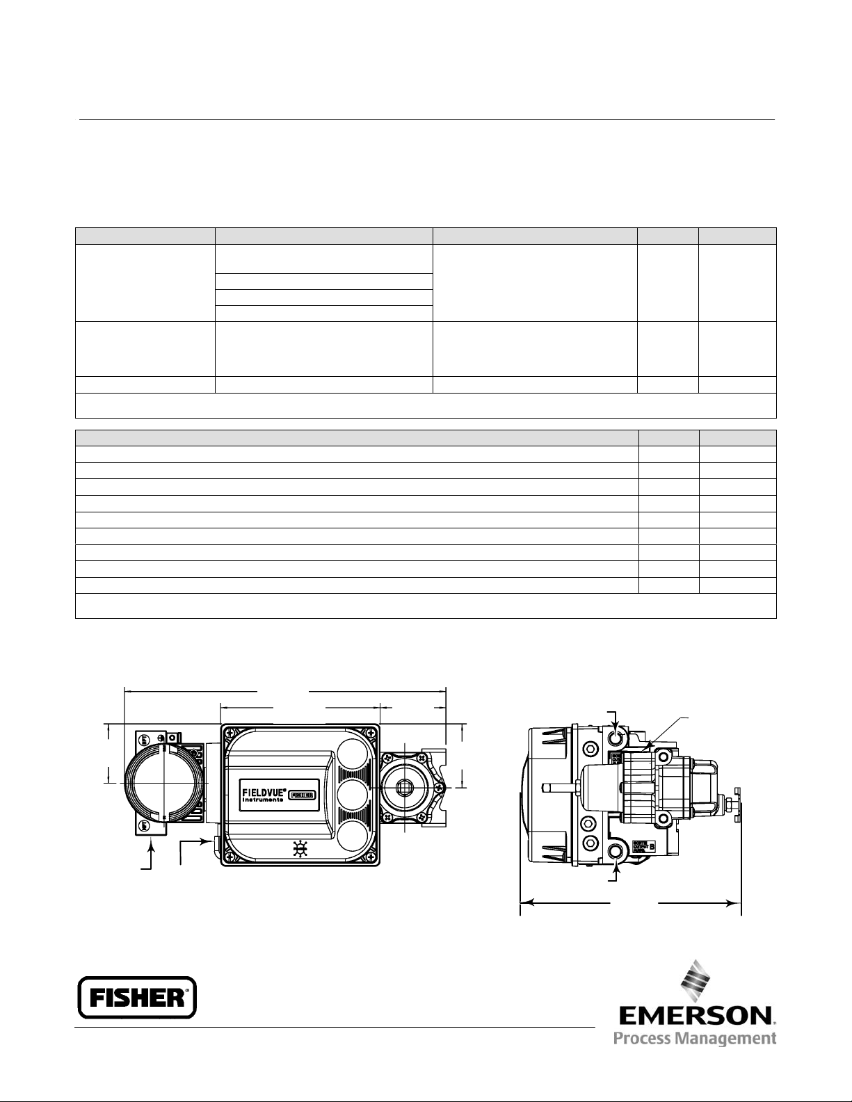
Figure 1. FIELDVUE DVC6200, DVC6200 SIS, DVC6200f, and DVC6200p Digital Valve Controller with Integrally
Mounted Filter Regulator
54.9
(2.16)
1/2-14 NPT
CONDUIT CONN
BOTH SIDES
www.Fisher.com
3/8-18 NPT
VENT CONN
298.4
(11.75)
148.1
(5.83)
61.1
(2.4)
mm
(INCH)
59.4
(2.34)
1/4-18 NPT
OUTPUT CONN A
1/4-18 NPT
OUTPUT CONN B
FISHER 67CFR
1/4-18 NPT
SUPPLY CONN
203.4
(8.00)
Page 2
Product Bulletin
62.1:DVC6200(S1)
October 2014
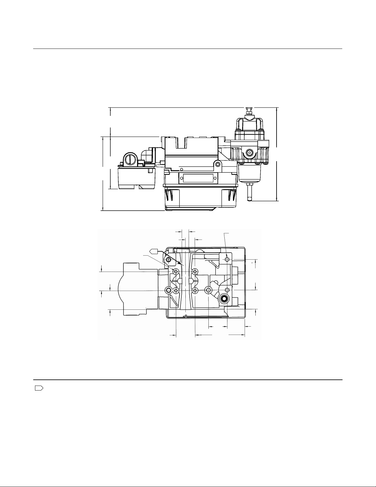
Figure 1. FIELDVUE DVC6200, DVC6200 SIS, DVC6200f, and DVC6200p Digital Valve Controller with Integrally
Mounted Filter Regulator (continued)
57.7
(2.27)
102.9
(4.05)
145.7
(5.73)
DVC6200 Digital Valve Controller
D103543X012
184.4
(7.26)
12.9
(0.51)
M6 X 1-6H
35.4
(1.39)
34.6
(1.36)
GE42896
1 Housing insert for SSTEM #210 magnet assembly (figure 9) inserted here.
1
(REGULATOR NOT SHOWN)
35.4
(1.39)
BACK VIEW
17.7
(0.70)
(1.38)
35
92.4
(3.64)
M8 X 1.25-6H
57
(2.24)
35.3
(1.38)
32.3
(1.27)
mm
(INCH)
2
Page 3
DVC6200 Digital Valve Controller
D103543X012
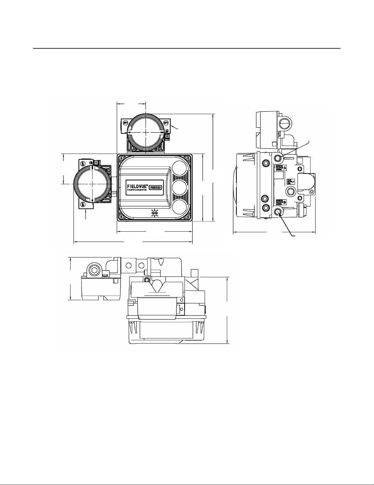
Figure 2. FIELDVUE DVC6205, DVC6205 SIS, DVC6205f, and DVC6205p
Remote Mount Base Unit Envelope Dimensions
56.6
(2.23)
Product Bulletin
62.1:DVC6200(S1)
October 2014
59.2
(2.33)
(3.13)
1/2-14 NPT
CONDUIT
CONNECTION
BOTH SIDES
79.6
233
(9.17)
148.1
(5.83)
1/2-14 NPT
CONDUIT
CONNECTION
BOTH SIDES
132
(5.20)
209.8
(8.26)
160.9
(6.33)
1/4-18 NPT
OUTPUT
CONNECTION A
1/4-18 NPT
OUTPUT
CONNECTION B
GE53722
123.9
(4.88)
mm
(INCH)
3
Page 4

Product Bulletin
62.1:DVC6200(S1)
October 2014
DVC6200 Digital Valve Controller
D103543X012
Figure 3. FIELDVUE DVC6215 Feedback Unit Envelope Dimensions
1/4-18 NPT
AIR PASSAGE
105.8
(4.16)
1/2-14 NPT
CONDUIT
CONNECTION
BOTH SIDES
150.3
(5.92)
GE53725
114.9
(4.53)
mm
(INCH)
Mounting hole locations for the DVC6215 feedback unit are the same as for the DVC6200, DVC6200 SIS, DVC6200f, and DVC6200p digital valve controller.
Refer to the back view in figure 1.
Magnet Assemblies
Figure 4. SStem #19 Magnet Assembly
(Also see in figure 6)
31.2
(1.23)
M4 X 0.7 - 6G (ALUMINUM)
M5 X 0.8 X 12 (SST)
2
61.05
(2.40)
18
(0.71)
32
(1.26)
16.05
(0.63)
5.5
(0.22)
mm
(INCH)
Figure 5. SStem #25 Magnet Assembly
(Also see in figure 6)
31.2
(1.23)
M4 X 0.7 - 6G (ALUMINUM)
M5 X 0.8 X 12 (SST)
2
61.05
(2.40)
18
(0.71)
32
(1.26)
5.5
(0.22)
15.9
(0.62)
mm
(INCH)
8 - 19 mm (0.32 - 0.75 INCH) TRAVEL RANGE
4
20 - 25 mm (0.76 - 1.00 INCH) TRAVEL RANGE
Page 5

DVC6200 Digital Valve Controller
D103543X012
Figure 6. SStem #38 Magnet Assembly
31.2
(1.23)
73.75
(2.90)
15.9
(0.62)
Product Bulletin
62.1:DVC6200(S1)
October 2014
6.3
2
(0.25)
18
M4 X 0.7 - 6G (ALUMINUM)
M5 X 0.8 X 12 (SST)
(0.71)
32
(1.26)
(0.22)
26 - 38 mm (1.01 - 1.50 INCH) TRAVEL RANGE
Figure 7. SStem #50 Magnet Assembly (Also see in figure 6)
28.5
(1.12)
2
86.37
(3.40)
5.5
6.3
(0.25)
10
(0.39)
2
mm
(INCH)
18.7
(0.74)
M4 X 0.7 - 6G (ALUMINUM)
M5 X 0.8 X 12 (SST)
18
(0.71)
31.8
(1.25)
57.4
(2.26)
39 - 50 mm (1.51 - 2.00 INCH) TRAVEL RANGE
mm
(INCH)
5
Page 6

Product Bulletin
62.1:DVC6200(S1)
October 2014
DVC6200 Digital Valve Controller
D103543X012
Figure 8. SStem #100 Magnet Assembly (Also see in figure 6)
28.5
(1.12)
M4 X 0.7 - 6G (ALUMINUM)
M5 X 0.8 X 12 (SST)
2
137.18
(5.40)
18
(0.71)
31.8
(1.25)
108.2
(4.26)
51 - 100 mm (2.01 - 4.00 INCH) TRAVEL RANGE
Figure 9. SStem #210 Magnet Assembly (Also see in figure 6)
2
261.83
(10.31)
10
(0.39)
18.7
(0.74)
mm
(INCH)
18.7
(0.74)
M4 X 0.7 - 6G (ALUMINUM)
M5 X 0.8 X 12 (SST)
101 - 210 mm (4.01 - 8.25 INCH) TRAVEL RANGE
2.5
(0.10)
HOUSING INSERT FOR SSTEM #210 MAGNET ASSEMBLY
1 Refer to back view of figure 1 for housing insert placement.
18
(0.71)
58
(2.28)
71.7
(2.82)
12.05
(0.47)
28.5
(1.12)
5.5
(0.22)
1
mm
(INCH)
6
Page 7

DVC6200 Digital Valve Controller
D103543X012
Figure 10. RShaft Window Magnet Assemblies
174.6
(6.88)
194
(7.64)
57
(2.24)
33.3
(1.31)
Product Bulletin
62.1:DVC6200(S1)
October 2014
114.6
(4.51)
95.3
(3.75)
29.5
(1.16)
39.7
(1.56)
54.9
(2.16)
RSHAFT WINDOW #1
5.3
(0.21)
BRACKET
SPRING, BIAS
74
(2.91)
(4.29)
109
5 X j 9 (0.35) THRU
4 X j 9.7 (0.38) THRU
29.5
(1.16)
39.7
(1.56)
49.2
(1.94)
RSHAFT WINDOW #2
BRACKET
SPRING,
BIAS
mm
(INCH)
7
Page 8

Product Bulletin
62.1:DVC6200(S1)
October 2014
DVC6200 Digital Valve Controller
D103543X012
Figure 11. RShaft End Mount Magnet Assembly
4 X j 3.4 (0.13) THRU
j 22 (0.87)
8.2
(0.32)
j 28 (1.10)
36.8
(1.45)
Related Documents
n Bulletin 62.1:DVC6200—DVC6200 Digital
Valve Controller (D103415X012)
n Bulletin 62.1:DVC6200 SIS—DVC6200 SIS
Digital Valve Controller (D103555X012)
n Bulletin 62.1:DVC6200f—DVC6200f Digital
Valve Controller (D103399X012)
n Bulletin 62.1:DVC6200p—DVC6200p Digital
Valve Controller (D103564X012)
All documents are available from your Emerson
Process Management sales office. Also visit our
website at www.FIELDVUE.com.
7.2
(0.28)
mm
(INCH)
Neither Emerson, Emerson Process Management, nor any of their affiliated entities assumes responsibility for the selection, use or maintenance
of any product. Responsibility for proper selection, use, and maintenance of any product remains solely with the purchaser and end user.
Fisher and FIELDVUE are marks owned by one of the companies in the Emerson Process Management business unit of Emerson Electric Co. Emerson Process
Management, Emerson, and the Emerson logo are trademarks and service marks of Emerson Electric Co. All other marks are the property of their respective
owners.
The contents of this publication are presented for informational purposes only, and while every effort has been made to ensure their accuracy, they are not
to be construed as warranties or guarantees, express or implied, regarding the products or services described herein or their use or applicability. All sales are
governed by our terms and conditions, which are available upon request. We reserve the right to modify or improve the designs or specifications of such
products at any time without notice.
Emerson Process Management
Marshalltown, Iowa 50158 USA
Sorocaba, 18087 Brazil
Chatham, Kent ME4 4QZ UK
Dubai, United Arab Emirates
Singapore 128461 Singapore
www.Fisher.com
E 2011, 2014 Fisher Controls International LLC. All rights reserved.
8
 Loading...