


Instruction Manual |
DLC3100 Digital Level Controller |
D104213X012 |
July 2019 |
|
|
Fisher™ FIELDVUE™ DLC3100 and DLC3100 SIS
Digital Level Controllers
This manual applies to:
Device Type |
130D |
Device Revision |
1 |
Hardware Revision |
1 |
|
|
Firmware Revision |
1.0.9 |
|
|
DD Revision |
1 |
|
|
Contents |
|
Section 1 Introduction and Specifications . . . . . . . . . |
3 |
Scope of Manual . . . . . . . . . . . . . . . . . . . . . . . . . . . . . |
3 |
Installation , Mounting and Electrical Connections, |
|
and Initial Configuration and Calibration using |
|
the Local User Interface . . . . . . . . . . . . . . . . . . . . |
3 |
Conventions Used . . . . . . . . . . . . . . . . . . . . . . . . . . . |
3 |
Description . . . . . . . . . . . . . . . . . . . . . . . . . . . . . . . . . |
3 |
DLC3100 Digital Level Controller . . . . . . . . . . . |
3 |
249 Caged Sensors . . . . . . . . . . . . . . . . . . . . . . . |
5 |
249 Cageless Sensors . . . . . . . . . . . . . . . . . . . . . |
5 |
Related Documents . . . . . . . . . . . . . . . . . . . . . . . . . . |
5 |
Educational Services . . . . . . . . . . . . . . . . . . . . . . . . . |
8 |
Section 2 Electrical Connections . . . . . . . . . . . . . . . . |
13 |
Test Connections . . . . . . . . . . . . . . . . . . . . . . . . . . . |
13 |
Alarm Conditions . . . . . . . . . . . . . . . . . . . . . . . . . . . |
13 |
Loop Test . . . . . . . . . . . . . . . . . . . . . . . . . . . . . . . . . |
14 |
Section 3 Overview . . . . . . . . . . . . . . . . . . . . . . . . . . . |
15 |
Status . . . . . . . . . . . . . . . . . . . . . . . . . . . . . . . . . . . . |
15 |
Primary Purpose Variables . . . . . . . . . . . . . . . . . . . . |
15 |
Device Information . . . . . . . . . . . . . . . . . . . . . . . . . |
15 |
Section 4 Configuration and Calibration using |
|
AMS Device Manager or a Field Communicator . . . |
17 |
Configuration Advice . . . . . . . . . . . . . . . . . . . . . . . . |
20 |
Force Mode . . . . . . . . . . . . . . . . . . . . . . . . . . . . |
20 |
Write Protection . . . . . . . . . . . . . . . . . . . . . . . . |
20 |
Level Offset . . . . . . . . . . . . . . . . . . . . . . . . . . . . |
20 |
Initial Setup . . . . . . . . . . . . . . . . . . . . . . . . . . . . . . . . |
21 |
Device Setup . . . . . . . . . . . . . . . . . . . . . . . . . . . |
21 |
PV Setup . . . . . . . . . . . . . . . . . . . . . . . . . . . . . . |
23 |
Process Setup . . . . . . . . . . . . . . . . . . . . . . . . . . |
23 |
Figure 1. Fisher DLC3100 Digital Level Controller
X1456
Manual Setup . . . . . . . . . . . . . . . . . . . . . . . . . . . . . . 24
General . . . . . . . . . . . . . . . . . . . . . . . . . . . . . . . 25
Device . . . . . . . . . . . . . . . . . . . . . . . . . . . . . . . . 25
Sensor . . . . . . . . . . . . . . . . . . . . . . . . . . . . . . . . 26
Process . . . . . . . . . . . . . . . . . . . . . . . . . . . . . . . . 26
HART . . . . . . . . . . . . . . . . . . . . . . . . . . . . . . . . . 27
Safety Recovery . . . . . . . . . . . . . . . . . . . . . . . . . 27
Alert Setup . . . . . . . . . . . . . . . . . . . . . . . . . . . . . . . . 28
Primary Variable . . . . . . . . . . . . . . . . . . . . . . . . 28
Rate Limit . . . . . . . . . . . . . . . . . . . . . . . . . . . . . . 29
Temperature . . . . . . . . . . . . . . . . . . . . . . . . . . . 29
Operational . . . . . . . . . . . . . . . . . . . . . . . . . . . . 30
Informational . . . . . . . . . . . . . . . . . . . . . . . . . . 30
Input Compensation . . . . . . . . . . . . . . . . . . . . . 30
Hardware . . . . . . . . . . . . . . . . . . . . . . . . . . . . . . 31
Program and Memory . . . . . . . . . . . . . . . . . . . 31
Alert Record . . . . . . . . . . . . . . . . . . . . . . . . . . . . 31
Calibration . . . . . . . . . . . . . . . . . . . . . . . . . . . . . . . . 32
Two Points Calibration . . . . . . . . . . . . . . . . . . . 32
Min/Max Calibration . . . . . . . . . . . . . . . . . . . . . 33
Weight Calibration . . . . . . . . . . . . . . . . . . . . . . 34
www.Fisher.com
DLC3100 Digital Level Controller |
Instruction Manual |
July 2019 |
D104213X012 |
|
|
Two Points Time Delay Calibration . . . . . . . . . |
35 |
Zero Trim . . . . . . . . . . . . . . . . . . . . . . . . . . . . . . |
36 |
Gain Trim . . . . . . . . . . . . . . . . . . . . . . . . . . . . . . |
36 |
Torque Rate Gain . . . . . . . . . . . . . . . . . . . . . . . |
36 |
Accuracy Considerations . . . . . . . . . . . . . . . . . . . . . |
37 |
Effect of Proportional Band . . . . . . . . . . . . . . . |
37 |
Density Variations in Interface Applications . . |
37 |
Extreme Process Temperatures . . . . . . . . . . . . |
38 |
Temperature Compensation . . . . . . . . . . . . . . |
38 |
Section 5 Service Tools . . . . . . . . . . . . . . . . . . . . . . . |
39 |
Active Alerts . . . . . . . . . . . . . . . . . . . . . . . . . . . . . . . |
39 |
Tests . . . . . . . . . . . . . . . . . . . . . . . . . . . . . . . . . . . . . |
40 |
Reset/Restore Device . . . . . . . . . . . . . . . . . . . . . . . . |
41 |
Section 6 Maintenance and Troubleshooting . . . . . |
42 |
Alert Messages . . . . . . . . . . . . . . . . . . . . . . . . . . . . . |
42 |
Hardware Diagnostics . . . . . . . . . . . . . . . . . . . . . . . |
43 |
Removing the DLC3100 from the Sensor . . . . . . . |
45 |
Front Cover Assembly . . . . . . . . . . . . . . . . . . . . . . . |
48 |
Removing the Front Cover Assembly . . . . . . . |
48 |
Replacing the Front Cover Assembly . . . . . . . |
49 |
Main Electronics Board . . . . . . . . . . . . . . . . . . . . . . |
49 |
Removing the Main Electronics Board . . . . . . |
49 |
Replacing the Main Electronics Board . . . . . . . |
49 |
LCD Assembly . . . . . . . . . . . . . . . . . . . . . . . . . . . . . . |
50 |
Removing the LCD Assembly . . . . . . . . . . . . . . |
50 |
Replacing the LCD Assembly . . . . . . . . . . . . . . |
50 |
Terminal Box Electronics Board . . . . . . . . . . . . . . . |
50 |
Removing the Terminal Box |
|
Electronics Board . . . . . . . . . . . . . . . . . . . . . |
50 |
Replacing the Terminal Box |
|
Electronics Board . . . . . . . . . . . . . . . . . . . . . |
51 |
Packing for Shipment . . . . . . . . . . . . . . . . . . . . . . . |
51 |
Section 7 Parts . . . . . . . . . . . . . . . . . . . . . . . . . . . . . . |
52 |
Parts Ordering . . . . . . . . . . . . . . . . . . . . . . . . . . . . . |
52 |
Parts Kits . . . . . . . . . . . . . . . . . . . . . . . . . . . . . . . . . . |
52 |
Parts List . . . . . . . . . . . . . . . . . . . . . . . . . . . . . . . . . . |
52 |
Mounting Kits . . . . . . . . . . . . . . . . . . . . . . . . . . . . . . |
56 |
Sunshade . . . . . . . . . . . . . . . . . . . . . . . . . . . . . . . . . |
58 |
Appendix A Principle of Operation . . . . . . . . . . . . . . |
60 |
HART Communication . . . . . . . . . . . . . . . . . . . . . . . |
60 |
Multidrop Communication . . . . . . . . . . . . . . . . . . . |
60 |
Digital Level Controller Operation . . . . . . . . . . . . . |
61 |
Appendix B Field Communicator Fast-Key |
|
Sequence and Menu Tree . . . . . . . . . . . . . . . . . . . . . |
65 |
2
Instruction Manual |
DLC3100 Digital Level Controller |
D104213X012 |
July 2019 |
|
|
Section 1
Introduction and Specifications
Scope of Manual
This instruction manual is a supplement to the DLC3100 and DLC3100 SIS Quick Start Guide (D104214X012) that ships with every digital level controller. This instruction manual includes specifications, operating, and maintenance information for FIELDVUE DLC3100 and DLC3100 SIS digital level controllers.
Notes
The DLC3100 SIS is identified by a label affixed to the terminal box cover.
Unless otherwise noted, the information in this document applies to both DLC3100 and DLC3100 SIS. However, for simplicity, the DLC3100 model name will be used throughout.
This instruction manual supports the 475 Field Communicator with device description revision 1, used with DLC3100 instruments with firmware revision 1.0.9. You can obtain information about the process, instrument, or sensor using the Field Communicator. Contact your Emerson sales office to obtain the appropriate software.
Do not install, operate, or maintain a DLC3100 digital level controller without being fully trained and qualified in valve, actuator, and accessory installation, operation, and maintenance. To avoid personal injury or property damage, it is important to carefully read, understand, and follow all the contents of this manual, including all safety cautions and warnings. If you have any questions regarding these instructions, contact your Emerson sales office before proceeding.
Installation, Mounting and Electrical Connections, and Initial Configuration and Calibration using the Local User Interface
Refer to the DLC3100 and DLC3100 SIS Quick Start Guide (D104214X012) for installation and connection information, as well as initial configuration and calibration using the local user interface. If a copy of this quick start guide is needed contact your Emerson sales office or visit Fisher.com.
Conventions Used
This manual describes using the Field Communicator to configure and calibrate the digital level controller.
Procedures that require the use of the Field Communicator have the text path and the sequence of numeric keys required to display the desired Field Communicator menu.
Description
DLC3100 Digital Level Controller
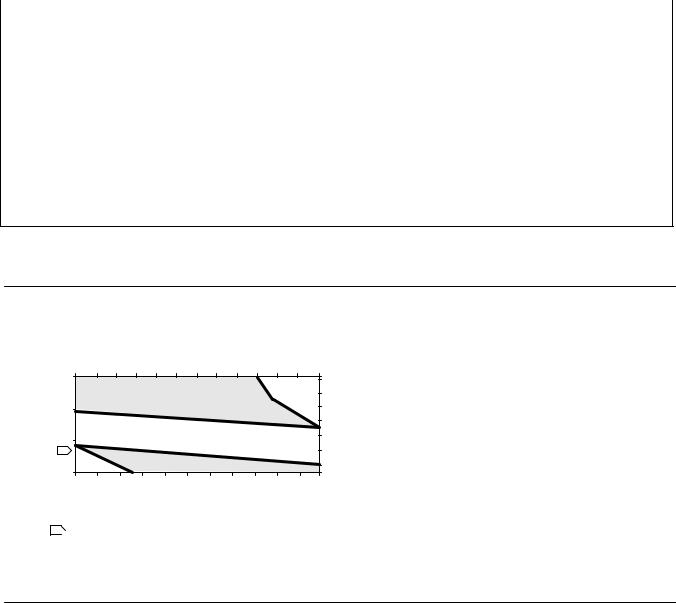
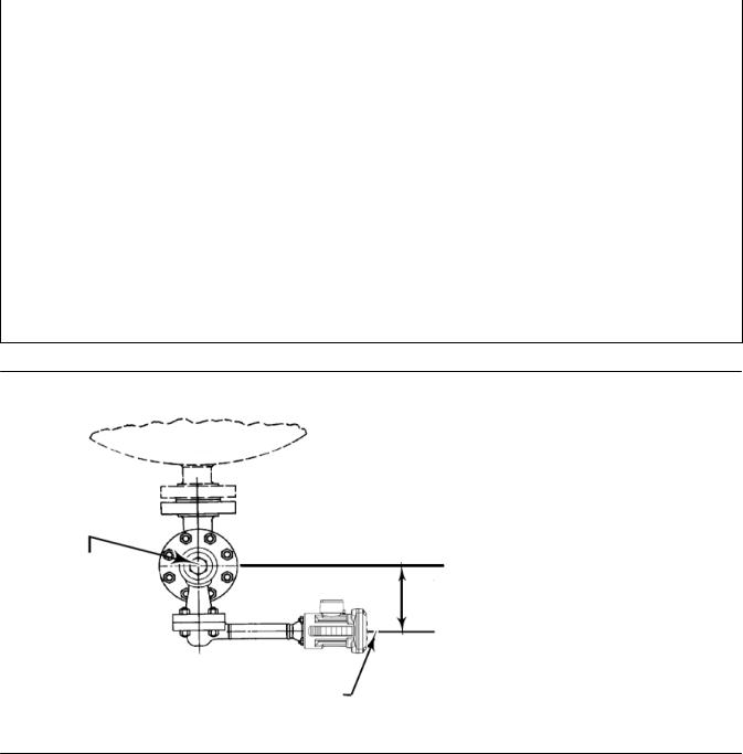
DLC3100 digital level controllers (figure 2) are used with level sensors to measure liquid level, the level of interface between two liquids, or liquid density. Changes in level or density exert a buoyant force on a displacer, which rotates the torque tube shaft (see figure 3). This rotary motion is applied to the digital level controller, transformed to an electrical signal and digitized. The digital signal is compensated and processed per user configuration requirements, and converted back to a 4-20 mA analog electrical signal. See the block diagram in figure 4.
3

DLC3100 Digital Level Controller |
|
Instruction Manual |
July 2019 |
|
D104213X012 |
|
|
|
|
|
|
Figure 2. Fisher DLC3100 Digital Level Controller |
|
Figure 3. Fisher 249 Torque Tube Rotation |
TORQUE
TUBE
DISPLACER
X1461 |
X1501 |
|
Figure 4. Mechanical Architecture
|
|
|
Main Electronic Compartment - Ex 'd' IP66 Enclosure |
|
|
|
Magnetic |
LCD (with reed |
Terminal |
|
|
Push Buttons |
Compartment |
|
|
|
(with magnets) |
switches) |
(with cover) |
|
|
|
|
Electrical |
|
|
|
|
Electrical |
|
Mechanical |
Magnetic |
|
Electrical |
|
|
|
||
249 Torque Tube |
|
Lever Assembly |
Hall Sensor |
Main PCB |
Mechanical
Lock Mechanism
(with magnets)
4

Instruction Manual |
DLC3100 Digital Level Controller |
D104213X012 |
July 2019 |
|
|
Several operations with the DLC3100 can be performed using the Field Communicator. The digital level controller can be configured, calibrated, or tested. Using the HART protocol, information from the field can be integrated into control systems or be received on a single loop basis.
DLC3100 digital level controllers are designed to directly replace standard pneumatic and electro-pneumatic level transmitters. DLC3100 digital level controllers mount on a wide variety of caged and cageless 249 level sensors. They can also be mounted on other manufacturers’ displacer type level sensors with designed mounting kits.
CAUTION
There are many magnets used in the DLC3100 (lever assembly, push button, coupling handle). Care must be taken to avoid having a high powered magnet in close proximity. This could cause permanent damage to the DLC3100. Potential sources of damaging equipment include, but are not limited to: transformers, DC motors, stacking magnet assemblies.
General Guidelines for use of High Power Magnets:
Use of high power magnets in close proximity to any instrument which is operating a process should be avoided. Regardless of the instrument model, high power magnets can affect its functionality.
249 Caged Sensors
249, 249B, 249BF, 249C, 249K and 249L sensors side-mount on the vessel with the displacer mounted inside a cage outside the vessel.
249 Cageless Sensors
249BP, 249CP and 249P sensors top-mount on the vessel with the displacer hanging down into the vessel. 249VS sensor side-mounts on the vessel with the displacer hanging out into the vessel.
249W wafer-style sensor mounts on top of a vessel or on a customer-supplied cages.
Related Documents
Other documents containing information related to the DLC3100 digital level controllers and 249 sensors include:
D FIELDVUE DLC3100 and DLC3100 SIS Quick Start Guide (D104214X012)
D CSA (United States and Canada) Hazardous Area Approvals - DLC3100 Digital Level Controller (D104232X012)
D ATEX and IECEx Hazardous Area Approvals - DLC3100 Digital Level Controller (D104233X012)
D Fisher 249 Caged Displacer Sensors Instruction Manual (D200099X012)
D Fisher 249 Cageless Displacer Sensors Instruction Manual (D200100X012)
D Fisher 249VS Cageless Displacer Sensor Instruction Manual (D103288X012)
D Fisher 249W Cageless Wafer Style Level Sensor Instruction Manual (D102803X012)
D Simulation of Process Conditions for Calibration of Fisher Level Controllers and Transmitters (D103066X012)
D Bolt Torque Information (D103220X012)
D Bulletin 11.2:DLC3100 - FIELDVUE DLC3100 and DLC3100 SIS Digital Level Controllers (D104216X012)
D Bulletin 34.2:249 - Fisher 249 Sensor, Level Controller, and Transmitter Dimensions (D200039X012) These documents are available from your Emerson sales office or at Fisher.com.
5

DLC3100 Digital Level Controller |
Instruction Manual |
July 2019 |
D104213X012 |
|
|
Table 1. Fisher DLC3100 Specifications |
|
|
|
Available Configurations
Mounts on caged and cageless 249 sensors
Function: Transmitter
Communications Protocol: HART
Input Signal
Level, Interface, or Density(1): Rotary motion of torque tube shaft proportional to changes in liquid level, interface level, or density that change the buoyancy of a displacer.
Process Temperature: Interface for 2- or 3-wire 100 ohm platinum RTD for sensing process temperature, or optional user-entered target
temperature to permit compensating for changes in specific density.
Output Signal
Analog: 4 to 20 mA DC
J Direct action—increasing level, interface, or density increases output; or
J Reverse action—increasing level, interface, or density decreases output
High saturation: 20.5 mA
Low saturation: 3.8 mA
High alarm(2): > 21.0 mA
Low Alarm(2): < 3.6 mA
Digital: HART 1200 Baud Frequency Shift Keyed (FSK)
HART impedance requirements must be met to enable communication. Total shunt impedance across the master device connections (excluding the master and transmitter impedance) must be between 230 and 600 ohms.
The transmitter HART receive impedance is defined as:
Rx: 30.2 k ohms and Cx: 5.45 nF
Supply Requirements
12 to 30 volts DC; 25 mA
Instrument has reverse polarity protection.
A minimum compliance voltage of 17.75 VDC (due to HART impedance requirement) is required to guarantee HART communication.
Transient Voltage Protection
Pulse Waveform |
Max VCL @ Ipp |
Ipp |
|
Rise Time |
Decay |
(Clamping |
(Peak Pulse |
(ms) |
to 50% (ms) |
Voltage) (V) |
Current) (A) |
10 |
1000 |
48.4 |
12.4 |
|
|
|
|
Electrical Classification
Overvoltage Category II per IEC 61010 clause 5.4.2d
Pollution Degree 4
Altitude Rating
Up to 2000 meters (6562 feet)
Ambient Temperature
The combined temperature effect on zero and span without the 249 sensor is less than 0.02% of full scale per degree Celsius over the operating range -40 to 80_C (-40 to 176_F)
LCD operating temperature limits: -20 to 70_C (-4 to 158_F)(3)
Process Temperature
The process density and torque rate are affected by the process temperature (figure 6). Temperature compensation can be implemented to correct for process density changes.
Process Density
The sensitivity to error in knowledge of process density is proportional to the differential density of the calibration. If the differential specific gravity is 0.2, and error of 0.02 specific gravity units in knowledge of a process fluid density represents 10% of span.
Hazardous Area
CSA
Class/Division: Intrinsically Safe, Explosion-proof(4), Division 2, Dust Ignition-proof
Zone: Intrinsically Safe, Flameproof, Type n, Dust by intrinsic safety and Enclosure
ATEX/IECEx—Flameproof, Intrinsic Safety, Dust by Intrinsic Safety
Electrical Housing
IP66, Type 4X
Electrical Connections: Two 1/2-14 NPT internal conduit connections. Both are at the bottom of terminal box.
-continued-
6

Instruction Manual |
DLC3100 Digital Level Controller |
D104213X012 |
July 2019 |
|
|
Table 1. Fisher DLC3100 Specifications (continued) |
|
Electromagnetic Compatibility
DLC3100 meets EN61326-1:2013
Performance is shown in table 2
DLC3100 SIS meets EN61326-3-2:2008
Performance is shown in table 3
DLC3100 SIS
Safety Instrumented System Classification
SIL2 capable - certified by exida Consulting LLC
Performance
|
DLC3100 |
w/ NPS 3 |
|
|
Performance |
249W, Using |
w/ All Other |
||
Digital Level |
||||
Criteria |
a 14 inch |
249 Sensors |
||
Controller(1) |
||||
|
Displacer |
|
||
|
|
|
||
Independent |
$0.25% of |
$0.8% of |
$0.5% of |
|
Linearity |
output span |
output span |
output span |
|
|
|
|
|
|
Hysteresis |
<0.2% of |
- - - |
- - - |
|
output span |
||||
|
|
|
||
|
|
|
|
|
Repeatability |
$0.1% of full |
$0.5% of |
$0.3% of |
|
scale output |
output span |
output span |
||
|
||||
|
|
|
|
|
Dead Band |
<0.05% of |
- - - |
- - - |
|
input span |
||||
|
|
|
||
|
|
|
|
|
Hysteresis plus |
- - - |
<1.0% of |
<1.0% of |
|
Deadband |
output span |
output span |
||
|
||||
|
|
|
|
NOTE: At full design span, reference conditions. 1. To lever assembly rotation inputs.
At effective proportional band (PB)<100%, linearity, dead band, and repeatability are derated by the factor (100%/PB)
Minimum Differential Specific Gravity
0.05 SGU
Construction Material
Housing and Cover: Low-copper aluminum die casting alloy
Internal: Aluminum, and stainless steel; encapsulated printed circuit board
Lever assembly: Plated steel, Neodymium iron boron magnets
Hall Guard: Thermoplastic elastomer
Weight
Less than 3.45 kg (7.57 lb)
Options
J Heat insulator (see figure 5 for use guidelines)
J Sunshade J Mountings for Masoneilan, Yamatake, Foxboro-Eckhardt sensors J Factory Calibration: available for instruments factory-mounted on 249 sensor, when application, process temperature and density are supplied
1.Density application is not available in DLC3100 SIS.
2.Only one of the High/Low alarm definition is available in a given configuration. Both alarms are NAMUR NE43 compliant.
3.Outside of this limit, LCD will not be readable but it will not affect the functionality of DLC3100 if the temperature is still within the normal limits. Push buttons will be disabled when instrument temperature is below -20°C (-4°F) or above 70°C (158°F) where LCD display might be intermittent.
4.Not for use in Ester and Ketone atmospheres.
Table 2. DLC3100 EMC Summary Results—Immunity per EN61326-1
Port |
Phenomenon |
Basic Standard |
Test Level |
Test Results(1)(2) |
|
|
Electrostatic |
IEC 61000-4-2 |
4 kV contact |
A |
|
|
discharge (ESD) |
8 kV air |
|||
|
|
|
|
||
|
|
|
80 to 1000 MHz @ 10V/m with 1 kHz AM at 80% |
|
|
Enclosure |
Radiated EM field |
IEC 61000-4-3 |
1400 to 2000 MHz @ 3V/m with 1 kHz AM at 80% |
A |
|
|
|
2000 to 2700 MHz @ 1V/m with 1 kHz AM at 80% |
|
|
|
|
|
|
|
|
|
|
|
|
|
|
|
|
Radiated power |
|
|
|
|
|
frequency magnetic |
IEC 61000-4-8 |
30 A/m at 50 and 60 Hz |
A |
|
|
field |
|
|
|
|
|
|
|
|
|
|
|
Burst |
IEC 61000-4-4 |
1 kV |
A |
|
|
|
|
|
|
|
I/O signal/control |
Surge |
IEC 61000-4-5 |
1kV (line to ground only, each) |
B |
|
|
Conducted RF |
IEC 61000-4-6 |
150 kHz to 80 MHz at 3 Vrms |
A |
|
|
|
|
|
|
|
|
Burst |
IEC 61000-4-4 |
2 kV |
A |
|
|
|
|
|
|
|
Protective earth |
Surge |
IEC 61000-4-5 |
2 kV (line to ground only) |
B |
|
|
Conducted RF |
IEC 61000-4-6 |
150 kHz to 80 MHz at 3 Vrms |
A |
|
1. A = No degradation during testing. B = Temporary degradation during testing, but is self recovering. Specification limit = +/- 1% of span.
2. HART communication was considered as “not relevant to the process” and is used primarily for configuration, calibration, and diagnostic purposes.
7
|
DLC3100 Digital Level Controller |
|
Instruction Manual |
||||
|
July 2019 |
|
|
|
D104213X012 |
||
|
|
|
|
|
|
|
|
Table 3. DLC3100 SIS EMC Summary Results—Immunity per EN61326-3-2 |
|
|
|
||||
|
Port |
Phenomenon |
Basic Standard |
Test Level |
Test Results(1)(2) |
|
|
|
|
Electrostatic |
IEC 61000-4-2 |
6 kV contact |
A |
||
|
|
discharge (ESD) |
8 kV air |
||||
|
|
|
|
|
|
||
|
|
|
|
|
|
|
|
|
|
|
|
80 to 1000 MHz @ 10V/m with 1 kHz AM at 80% |
|
|
|
|
Enclosure |
Radiated EM field |
IEC 61000-4-3 |
1400 to 2000 MHz @ 10V/m with 1 kHz AM at 80% |
A |
||
|
|
|
2000 to 2700 MHz @ 3V/m with 1 kHz AM at 80% |
|
|
|
|
|
|
|
|
|
|
|
|
|
|
|
|
|
|
|
|
|
|
Radiated power |
|
|
|
|
|
|
|
frequency magnetic |
IEC 61000-4-8 |
100 A/m at 50 and 60 Hz |
A |
||
|
|
field |
|
|
|
|
|
|
|
|
|
|
|
|
|
|
|
Burst |
IEC 61000-4-4 |
1 kV |
A |
||
|
|
|
|
|
|
|
|
|
I/O signal/control |
Surge |
IEC 61000-4-5 |
1 kV (line to ground only, each) |
FS |
|
|
|
|
Conducted RF |
IEC 61000-4-6 |
10 kHz to 80 MHz at 10 Vrms |
A |
||
|
|
|
|
|
|
|
|
|
|
Burst |
IEC 61000-4-4 |
2 kV |
A |
||
|
|
|
|
|
|
|
|
|
Protective earth |
Surge |
IEC 61000-4-5 |
1 kV (line to ground only) |
A |
|
|
|
|
Conducted RF |
IEC 61000-4-6 |
10 kHz to 80 MHz at 10 Vrms |
A |
||
|
|
|
|
|
|
|
|
1. A = No degradation during testing. B = Temporary degradation during testing, but is self recovering. FS = Fail Safe. Specification limit = +/- 2% of span. 2. HART communication was considered as “not relevant to the process” and is used primarily for configuration, calibration, and diagnostic purposes.
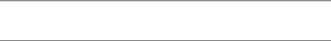
Figure 5. Guidelines for Use of Optional Heat Insulator Assembly
|
|
|
|
AMBIENT TEMPERATURE (_C) |
|
|
|
PROCESS TEMPERATURE ( C) |
||||||
PROCESS TEMPERATURE ( F) |
-40 |
-30 |
-20 |
-10 |
0 |
10 |
20 |
30 |
40 |
50 |
60 |
70 |
80 425 |
|
800 |
|
|
|
|
|
|
|
|
|
|
|
400 |
||
|
|
|
|
|
|
|
|
|
|
|
TOO |
|||
|
|
|
|
HEAT INSULATOR |
|
|
300 |
|||||||
|
|
|
|
|
|
HOT |
||||||||
|
|
|
|
REQUIRED |
|
|
|
|
||||||
400 |
|
|
|
|
|
|
|
200 |
||||||
|
|
|
|
|
|
|
|
|
|
|
||||
|
|
|
|
|
|
|
|
|
|
|
|
100 |
||
0 |
|
|
NO HEAT INSULATOR NECESSARY |
|
0 |
|||||||||
|
|
|
|
|
|
|
|
|
|
|
|
|||
1 |
TOO |
|
HEAT INSULATOR |
|
|
|
|
|
|
-100 |
||||
|
|
|
|
|
|
|
|
-200 |
||||||
-325 |
COLD |
|
REQUIRED |
|
|
|
|
|
|
|
||||
|
|
|
|
|
|
|
|
|
||||||
|
|
|
|
|
|
|
|
|
|
|
|
|||
-40 |
-20 |
0 |
20 |
40 |
60 |
|
80 |
100 |
120 |
140 |
160 176 |
|||
AMBIENT TEMPERATURE (_F)
STANDARD TRANSMITTER
NOTES:
1Ã FOR PROCESS TEMPERATURES BELOW -29_C (-20_F) AND ABOVE 204_C (400_F) SENSOR MATERIALS MUST BE APPROPRIATE FOR THE PROCESS; SEE TABLE 5.
2. IF AMBIENT DEW POINT IS ABOVE PROCESS TEMPERATURE, ICE FORMATION MIGHT CAUSE INSTRUMENT MALFUNCTION AND REDUCE INSULATOR EFFECTIVENESS.
39A4070 B
A5494 1
Educational Services
For information on available courses contact:
Emerson Automation Solutions Educational Services, Registration
Phone: +1-641-754-3771 or +1-800-338-8158 e mail: education@emerson.com emerson.com/fishervalvetraining
8

Instruction Manual |
DLC3100 Digital Level Controller |
D104213X012 |
July 2019 |
|
|
Figure 6. Theoretical Reversible Temperature Effect on Common Torque Tube Materials
TORQUE RATE REDUCTION
(NORMALIZED MODULUS OF RIGIDITY)
Gnorm
1.00 |
|
|
|
|
|
|
|
|
|
|
|
|
|
|
|
|
|
|
|
|
|
|
0.98 |
|
|
|
|
|
|
|
|
|
|
|
|
|
|
|
|
|
|
|
|
|
|
|
|
|
|
|
|
|
|
|
|
|
|
|
|
|
1 |
|
|
|
|
|
|
|
0.96 |
|
|
|
|
|
|
|
|
|
|
|
|
|
|
|
|
|
|
|
|
|
|
0.94 |
|
|
|
|
|
|
|
|
|
|
|
|
|
|
|
|
|
|
|
|
|
|
0.92 |
|
|
|
|
|
|
|
|
|
|
|
|
|
|
|
|
|
|
|
|
|
N05500 |
|
|
|
|
|
|
|
|
|
|
|
|
|
|
|
|
|
|
|
|
|
|
N06600 |
0.90 |
|
|
|
|
|
|
|
|
|
|
|
|
|
|
|
|
|
|
|
|
|
|
|
|
|
|
|
|
|
|
|
|
|
|
|
|
|
|
|
|
|
|
|
|
N10276 |
0.88 |
|
|
|
|
|
|
|
|
|
|
|
|
|
|
|
|
|
|
|
|
|
|
0.86 |
|
|
|
|
|
|
|
|
|
|
|
|
|
|
|
|
|
|
|
|
|
|
0.84 |
|
|
|
|
|
|
|
|
|
|
|
|
|
|
|
|
|
|
|
|
|
|
0.82 |
|
|
|
|
|
|
|
|
|
|
|
|
|
|
|
|
|
|
|
|
|
|
0.80 |
|
|
|
|
|
|
|
|
|
|
|
|
|
|
|
|
|
|
|
|
|
S31600 |
20 |
40 |
60 |
80 |
100 |
120 |
140 |
160 |
180 |
200 |
220 |
240 |
260 |
280 |
300 |
320 |
340 |
360 |
380 |
400 |
420 |
||
TEMPERATURE (_C)
TORQUE RATE REDUCTION
(NORMALIZED MODULUS OF RIGIDITY)
1.00
0.98
1 
0.96
Gnorm
0.94 |
|
|
|
|
|
|
|
|
|
|
|
|
|
|
|
0.92 |
|
|
|
|
|
|
|
|
|
|
|
|
|
|
N05500 |
|
|
|
|
|
|
|
|
|
|
|
|
|
|
|
|
|
|
|
|
|
|
|
|
|
|
|
|
|
|
|
N06600 |
0.90 |
|
|
|
|
|
|
|
|
|
|
|
|
|
|
|
|
|
|
|
|
|
|
|
|
|
|
|
|
|
|
N10276 |
0.88 |
|
|
|
|
|
|
|
|
|
|
|
|
|
|
|
0.86 |
|
|
|
|
|
|
|
|
|
|
|
|
|
|
|
0.84 |
|
|
|
|
|
|
|
|
|
|
|
|
|
|
|
0.82 |
|
|
|
|
|
|
|
|
|
|
|
|
|
|
|
0.80 |
|
|
|
|
|
|
|
|
|
|
|
|
|
|
S31600 |
50 |
100 |
150 |
200 |
250 |
300 |
350 |
400 |
450 |
500 |
550 |
600 |
650 |
700 |
750 |
800 |
TEMPERATURE (_F)
NOTE:
1 ÃDUE TO THE PERMANENT DRIFT THAT OCCURS NEAR AND ABOVE 260_C (500_F), N05500 IS NOT RECOMMENDED FOR TEMPERATURES ABOVE 232_C (450_F).
9

DLC3100 Digital Level Controller |
Instruction Manual |
|
July 2019 |
D104213X012 |
|
|
|
|
Table 4. Fisher 249 Sensor Specifications |
|
|
Input Signal |
equalizing connection styles are numbered and are |
|
Liquid Level or Liquid to Liquid Interface Level: |
shown in figure 7. |
|
|
||
From 0 to 100 percent of displacer length |
Mounting Positions |
|
Liquid Density: From 0 to 100 percent of |
||
displacement force change obtained with given |
Most level sensors with cage displacers have a |
|
displacer volume—standard volumes are |
||
rotatable head. The head may be rotated through |
||
JÉ980 cm3 (60 inches3) for 249C and 249CP sensors |
||
360 degrees to any of eight different positions. |
||
or JÉ1640 cm3 (100 inches3) for most other sensors; |
||
|
||
other volumes available depending upon sensor |
Construction Materials |
|
construction |
||
See tables 6, 7, and 8 |
||
|
||
Sensor Displacer Lengths |
|
See tables 7 and 8 footnotes
Sensor Working Pressures
Consistent with applicable ANSI pressure/temperature ratings for the specific sensor constructions shown in tables 7 and 8
Caged Sensor Connection Styles
Cages can be furnished in a variety of end connection styles to facilitate mounting on vessels; the
Operative Ambient Temperature
See table 5
For ambient temperature ranges, guidelines, and use of optional heat insulator see figure 5
Options
J Heat insulator J Gauge glass for pressures to 29 bar at 232_C (420 psig at 450_F), and J Reflex gauges for high temperature and pressure applications
Table 5. Allowable Process Temperatures for Common 249 Sensor Pressure Boundary Materials
MATERIAL |
PROCESS TEMPERATURE |
||
Min. |
Max. |
||
|
|||
Cast Iron |
-29_C (-20_F) |
232_C (450_F) |
|
|
|
|
|
Steel |
-29_C (-20_F) |
427_C (800_F) |
|
|
|
|
|
Stainless Steel |
-198_C (-325_F) |
427_C (800_F) |
|
|
|
|
|
N04400 |
-198_C (-325_F) |
427_C (800_F) |
|
|
|
|
|
Graphite |
|
|
|
Laminate/SST |
-198_C (-325_F) |
427_C (800_F) |
|
Gaskets |
|
|
|
|
|
|
|
N04400/PTFE |
-73_C (-100_F) |
204_C (400_F) |
|
Gaskets |
|||
|
|
||
|
|
|
|
Table 6. Displacer and Torque Tube Materials
Part |
Standard Material |
Other Materials |
|
|
|
|
316 Stainless Steel, |
||
Displacer |
304 Stainless Steel |
N10276, N04400, |
||
Plastic, and Special |
||||
|
|
|||
|
|
Alloys |
||
|
|
|
||
Displacer Stem |
|
N10276, N04400, |
||
Driver Bearing, |
316 Stainless Steel |
other Austenitic |
||
Displacer Rod and |
Stainless Steels, and |
|||
|
||||
Driver |
|
Special Alloys |
||
|
|
|
||
Torque Tube |
N05500(1) |
316 Stainless Steel, |
||
N06600, N10276 |
||||
|
|
|||
|
|
|
|
|
1. N05500 is not recommended for spring applications above 232_C (450_F). Contact your Emerson sales office or application engineer if temperatures exceeding this limit are required.
10
Instruction Manual |
DLC3100 Digital Level Controller |
D104213X012 |
July 2019 |
|
|
Table 7. Caged Displacer Sensors(1)
TORQUE TUBE |
|
STANDARD CAGE, HEAD, |
EQUALIZING CONNECTION |
|
PRESSURE RATING(2) |
|
|
SENSOR |
AND TORQUE TUBE ARM |
|
|
|
|
||
ORIENTATION |
Style |
|
Size (NPS) |
|
|||
|
MATERIAL |
|
|
|
|||
|
|
|
|
|
|||
|
|
|
|
|
|
|
|
|
249(3) |
Cast iron |
Screwed |
|
1 1/2 or 2 |
CL125 or CL250 |
|
|
|
|
|
||||
|
Flanged |
|
2 |
||||
|
|
|
|
|
|
||
|
|
|
|
|
|
|
|
|
|
|
Screwed or optional socket weld |
|
1 1/2 or 2 |
CL600 |
|
|
|
|
|
|
|
|
|
|
|
|
|
|
1 1/2 |
CL150, CL300, or |
|
|
249B, 249BF(4) |
Steel |
Raised face or optional ring type joint |
|
CL600 |
||
|
|
|
|||||
Torque tube |
|
|
flanged |
|
2 |
CL150, CL300, or |
|
arm rotatable |
|
|
|
|
CL600 |
||
|
|
|
|
|
|||
with respect to |
|
|
Screwed |
|
1 1/2 or 2 |
CL600 |
|
equalizing |
|
|
|
|
|
|
|
|
|
|
|
1 1/2 |
CL150, CL300, or |
||
connections |
|
|
|
|
|||
249C(3) |
316 stainless steel |
|
|
CL600 |
|||
Raised face flanged |
|
|
|||||
|
|
|
|
2 |
CL150, CL300, or |
||
|
|
|
|
|
|||
|
|
|
|
|
CL600 |
||
|
|
|
|
|
|
||
|
|
|
|
|
|
|
|
|
249K |
Steel |
Raised face or optional ring type joint |
|
1 1/2 or 2 |
CL900 or CL1500 |
|
|
flanged |
|
|||||
|
|
|
|
|
|
|
|
|
|
|
|
|
|
|
|
|
249L |
Steel |
Ring type joint flanged |
|
2(5) |
CL2500 |
|
1. Standard displacer lengths for all styles (except 249) are 14, 32, 48, 60, 72, 84, 96, 108 and 120 inches. The 249 uses a displacer with a length of either 14 or 32 inches. 2. EN flange connections available in EMA (Europe, Middle East and Africa).
3. Not available in EMA.
4. The 249BF available in EMA only. Also available in EN size DN 40 with PN 10 to PN 100 flanges and size DN 50 with PN 10 to PN 63 flanges. 5. Top connection is NPS 1 ring type joint flanged for connection styles F1 and F2.
Table 8. Cageless Displacer Sensors(1)
|
|
|
Standard Head(2), Wafer |
|
|
Mounting |
Sensor |
|
Body(6) and Torque Tube |
Flange Connection (Size) |
Pressure Rating(3) |
|
|
|
Arm Material |
|
|
|
249BP(4) |
|
Steel |
NPS 4 raised face or optional ring type joint |
CL150, CL300, or CL600 |
|
|
|
|
||
|
|
NPS 6 or 8 raised face |
CL150 or CL300 |
||
|
|
|
|
||
|
|
|
|
|
|
Mounts on |
249CP |
|
316 Stainless Steel |
NPS 3 raised face |
CL150, CL300, or CL600 |
|
|
|
|
|
|
|
|
|
|
CL900 or 1CL500 |
|
top of vessel |
|
|
|
NPS 4 raised face or optional ring type joint |
|
|
|
|
(EN PN 10 to DIN PN 250) |
||
|
249P(5) |
|
Steel or stainless steel |
|
|
|
|
|
|
||
|
|
NPS 6 or 8 raised face |
CL150, CL300, CL600, CL900, |
||
|
|
|
|
||
|
|
|
|
CL1500, or CL2500 |
|
|
|
|
|
|
|
|
|
|
|
|
|
|
|
|
WCC (steel) LCC (steel), or |
|
CL125, CL150, CL250, CL300, |
Mounts on |
|
|
For NPS 4 raised face or flat face |
CL600, CL900, or CL1500 |
|
249VS |
|
CF8M (316 stainless steel) |
|||
side of vessel |
|
|
(EN PN 10 to DIN PN 160) |
||
|
|
|
|||
|
|
|
|
||
|
|
|
|
|
|
|
|
|
WCC, LCC, or CF8M |
For NPS 4 buttweld end, XXZ |
CL2500 |
|
|
|
|
|
|
Mounts on top of |
|
|
WCC or CF8M |
For NPS 3 raised face |
CL150, CL300, or CL600 |
vessel or on |
|
|
|||
249W |
|
|
|
|
|
customer |
|
LCC or CF8M |
For NPS 4 raised face |
CL150, CL300, or CL600 |
|
|
|
||||
supplied cage |
|
|
|||
|
|
|
|
|
|
|
|
|
|
|
|
1. Standard displacer lengths are 14, 32, 48, 60, 72, 84, 96, 108, and 120 inches. |
|
|
|||
2. Not used with side mounted sensors. |
|
|
|
|
|
3. EN flange connections available in EMA (Europe, Middle East and Africa). |
|
|
|||
4. Not available in EMA. |
|
|
|
|
|
5. 249P available in EMA only. |
|
|
|
|
|
6. Wafer Body only applicable to the 249W. |
|
|
|
|
|
|
|
|
|
|
|
11
DLC3100 Digital Level Controller |
Instruction Manual |
July 2019 |
D104213X012 |
|
|
Figure 7. Style Number of Equalizing Connections
STYLE 1 |
STYLE 2 |
STYLE 3 |
STYLE 4 |
TOP & BOTTOM |
TOP & LOWER SIDE |
UPPER & LOWER SIDE |
UPPER SIDE & BOTTOM |
CONNECTIONS |
CONNECTIONS |
CONNECTIONS |
CONNECTIONS |
SCREWED (S-1) OR |
SCREWED (S-2) OR |
SCREWED (S-3) OR |
SCREWED (S-4) OR |
FLANGED (F-1) |
FLANGED (F-2) |
FLANGED (F-3) |
FLANGED (F-4) |
E1697
12

Instruction Manual |
DLC3100 Digital Level Controller |
D104213X012 |
July 2019 |
|
|
Section 2
Electrical Connections
Note
This information supplements the Electrical Connections section in the quick start guide (D104214X012) that shipped with your instrument. If a copy of this quick start guide is needed contact your Emerson sales office or visit Fisher.com.
Test Connections

 WARNING
Personal injury or property damage caused by fire or explosion may occur if this connection is attempted in an area which contains a potentially explosive atmosphere or has been classified as hazardous. Confirm that area classification and atmosphere conditions permit the safe removal of the terminal box cap before proceeding.
Test connections inside the terminal box can be used to measure loop current across an internal 1 ohm resistor.
1.Remove the terminal box cap.
2.Adjust the test meter to measure mV.
3.Connect the positive lead of the test meter to the + connection and the negative lead to the TEST connection inside the terminal box.
4.Measure Loop current as mV = mA. For example, if the meter measures 12.5 mV, it means the loop current is 12.5 mA.
5.Remove test leads and replace the terminal box cover.
Alarm Conditions
Each digital level controller continuously monitors its own performance during normal operation. This automatic diagnostic routine is a timed series of checks repeated continuously. If diagnostics detect a failure in the electronics, the instrument drives its output to trip alarm current either below 3.6 mA or above 21 mA, depending on the position (High/Low) of the alarm switch.
An alarm condition occurs when the self-diagnostics detect an error that would render the process variable measurement inaccurate, incorrect, or undefined, or a user defined threshold is violated. At this point the analog output of the unit is driven to a defined level either above or below the nominal 4-20 mA range, based on the position of the alarm switch. The factory default Alarm Switch setting is High.
Refer to table 9 for alerts that will trigger the Trip Alarm Current when enabled.
13

DLC3100 Digital Level Controller |
|
Instruction Manual |
|
July 2019 |
|
D104213X012 |
|
|
|
|
|
Table 9. Trip Alarm Current Default Setting |
|
|
|
|
|
|
|
Alerts |
|
Trip Alarm Current Default Setting |
|
Device Malfunction |
|
Enable |
|
|
|
|
|
Reference Voltage Failed |
|
Enable |
|
|
|
|
|
PV Analog Output Readback Limit Failed |
|
Enable |
|
|
|
|
|
Instrument Temperature Sensor Alert |
|
Enable |
|
|
|
|
|
Hall Sensor Alert |
|
Enable |
|
|
|
|
|
RTD Sensor Alert |
|
Enable |
|
|
|
|
|
Hall Diagnostic Failed |
|
Enable |
|
|
|
|
|
RTD Diagnostic Failed |
|
Enable |
|
|
|
|
|
Program Memory Failed |
|
Enable |
|
|
|
|
|
NVM Error |
|
Enable |
|
|
|
|
|
RAM Test Error Alert |
|
Enable |
|
|
|
|
|
Watchdog Reset Executed |
|
Enable |
|
|
|
|
|
PV HiHi Alert |
|
Disable |
|
|
|
|
|
PV LoLo Alert |
|
Disable |
|
|
|
|
|
Loop Test
Note
The DLC3100 must be put out of service during Loop Test. Place the loop into manual operation before putting device out of service as the DLC3100 output may not be valid.
When the DLC3100 is out of service, it is locked for exclusive access by the Primary/Secondary master that put it out of service. If the instrument reports Locked by HART or Access Restricted when you attempt to configure it, and a master of the original priority is not available, use Force Mode on the Local User Interface menu to force the instrument mode to In Service. You will then be able to take it out of service with your own master to make changes.
Loop Test can be used to verify the controller output, the integrity of the loop, and the operations of any recorders or similar devices installed in the loop. To initiate a loop test, perform the following procedure:
1.Connect a reference meter to the controller. To do so, either connect the meter to the test connections inside the terminal box (see Test Connections procedure) or connect the meter in the loop as shown in figure 8.
2. Access Loop Test via Service Tools > Maintenance > Tests > Loop Test (3-4-2-2).
3.Select OK after you set the control loop to manual. The Field Communicator displays the loop test menu.
4.Put the instrument to “Not in Service” and select analog output level: 4mA, 20mA or Other to manually input a value between 4 and 20 milliamps.
5.Check the reference meter to verify that it reads the value that is commanded. If the readings do not match, either the controller requires an output trim, or the meter is malfunctioning.
After completing the test procedure, the display returns to the loop test screen and allows you to choose another output value or end the test and put instrument back in service.
14
Instruction Manual |
DLC3100 Digital Level Controller |
D104213X012 |
July 2019 |
|
|
Section 3
Overview
Overview provides information about the current state of the instrument, measurement data, and device variables that are of interest.
Status
Name |
Status |
Description |
|
|
Good |
There are no active alerts and instrument is In Service. |
|
|
|
|
|
|
Failure |
The highest severity active alert is in the Failure category. |
|
Device |
|
|
|
Maintenance |
The highest severity active alert is in the Maintenance |
||
|
category. |
||
|
|
||
|
|
|
|
|
Advisory |
The highest severity active alert is in the Advisory category. |
|
|
|
|
|
Communications |
Polled |
Communication with digital level controller is established. |
|
|
|
||
Simulation Active |
Digital level controller is in alert simulation mode. |
||
|
|||
|
|
|
|
|
In Service |
Digital level controller is online and performing its function. |
|
Mode |
|
|
|
Not In Service |
Digital level controller is Out of Service. Output may not be |
||
|
valid. |
||
|
|
||
|
|
|
Primary Purpose Variables
Name |
Description |
Process Fluid |
Name of the process fluid. |
|
|
Process Fluid Compensated |
Density of the process fluid. If temperature compensation is enabled, the density |
Density |
value is after compensation. |
|
|
PV |
Actual measurement in percentage of span. |
|
|
PV Value |
Actual measurement in unit. |
|
|
Process Temperature |
Actual temperature of the process (via RTD or manual input). |
|
|
Analog Output |
Current output of the digital level controller, in milliamps. |
Device Information
Identification
Name |
Description |
Tag |
A unique name to identify the HART device, up to 8 characters. |
|
|
Long Tag |
A unique name to identify the HART device, up to 32 characters. |
|
|
Model |
Field device model: DLC3100 |
|
|
Device ID |
The ID of the printed wiring board in the instrument. |
|
|
Instrument Serial Number |
Serial number printed on the nameplate of the device. |
|
|
Sensor Serial Number |
Serial number printed on the nameplate of the 249 sensor. |
|
|
Instrument Assembly Code |
Unique code in device for traceability. |
|
|
15
DLC3100 Digital Level Controller |
Instruction Manual |
|
July 2019 |
|
D104213X012 |
|
|
|
Revisions |
|
|
|
|
|
Name |
Description |
|
HART Universal Revision |
The revision number of the HART Universal Commands used by the instrument. |
|
|
|
|
Device Revision |
The revision number of the instrument-to-HART communicator interface software. |
|
|
|
|
Hardware |
The revision number of the instrument hardware. |
|
|
|
|
Firmware |
The revision number of the instrument firmware. |
|
|
|
|
Alarm Type and Security
Name |
Value |
Description |
|
Alarm Switch |
High |
Analog output will be >= 21mA when Trip Alarm Current is activated. |
|
|
|
||
Low |
Analog output will be <= 3.6mA when Trip Alarm Current is activated. |
||
|
|||
|
|
|
|
|
Enable |
When protection is enabled, writing to parameters and calibration are |
|
Protection |
not allowed. |
||
|
|||
|
Disable |
When protection is disabled, device can be configured and calibrated. |
|
|
|
|
16

Instruction Manual |
DLC3100 Digital Level Controller |
D104213X012 |
July 2019 |
|
|
Section 4
Configuration and Calibration using AMS Device Manager or a Field Communicator
Note
Refer to the DLC3100 and DLC3100 SIS Quick Start Guide (D104214X012) for configuration and calibration using the local user interface. If a copy of this quick start guide is needed contact your Emerson sales office or visit Fisher.com.
DLC3100 has to be set to “Not In Service” during configuration and calibration which include:
D Device Setup
D PV Setup
D Process Setup
D Calibration
D Manual Setup
D Alert Setup
The DLC3100 will continue to regulate the current output based on lever assembly position. The output can be at failed current value (determine by alarm switch on the Main Electronics Board) depending on the device alerts/status. This current output shall not be treated as actual level/interface measurement as the device is “Not In Service”.
CAUTION
The control loop must be in manual before putting DLC3100 to Not In Service.
Note
When configuring the DLC3100 using the DD, the access of DLC3100 via Local User Interface will be locked.
If a DLC3100 digital level controller ships from factory mounted on a 249 sensor, initial setup and calibration may not be necessary. The factory enters the sensor data, couples the instrument to the sensor, and calibrates the instrument and sensor combination.
17

DLC3100 Digital Level Controller |
Instruction Manual |
July 2019 |
D104213X012 |
|
|
Note
If the digital level controller mounted on the sensor is received with the displacer blocked, or if the displacer is not connected, the instrument will be coupled to the torque tube assembly and the lever assembly unlocked. To place the unit in service, if the displacer is blocked, remove the rod and block at each end of the displacer and check the instrument calibration. (If the “factory cal” option was ordered, the instrument will be pre-compensated to the process conditions provided on the requisition, and may not appear to be calibrated if checked against room temperature with 0% and 100% water level inputs). If the displacer is not connected, hang the displacer on the torque tube.
If the digital level controller mounted on the torque tube arm and the displacer is not blocked when received (such as in skid mounted systems), the instrument will not be coupled to the torque tube assembly, and the lever assembly will be locked. To place the unit in service, couple the instrument to the sensor and unlock the lever assembly.
When the 249 assembly is properly connected and coupled to the digital level controller, establish the zero process condition and perform the Trim Zero procedure. The torque tube rate should not need to be recalibrated.
To review the configuration data entered by the factory, connect the instrument to a 24 VDC power supply as shown in figure 8. Connect the AMS Device Manager/Field Communicator to the instrument and turn it on. Go to Configure and review the data under Manual Setup and Alert Setup. If application data has been changed since the instrument was factory-configured, refer to the Manual Setup section for instructions on modifying configuration data.
Figure 8. Connecting to a Power Supply
230 W 3 RL 3 600 W |
|
− |
+ |
|
+ |
+ |
Reference meter |
|
||||
|
||||||
for calibration |
POWER |
|||||
|
or monitoring |
SUPPLY |
||||
|
operation. May |
|
|
|
|
|
|
− |
|||||
|
|
|
|
|||
|
be a voltmeter |
|||||
−across 250 ohm
resistor or a |
|
current meter. + |
− |
Signal loop may be grounded at any point or left ungrounded.
Field Communicator may be connected at any termination point in the signal loop other than across the power supply. Signal loop must have between 230 and 600 ohms load for communication.
18
Instruction Manual |
DLC3100 Digital Level Controller |
D104213X012 |
July 2019 |
|
|
For instruments not mounted on a level sensor or when replacing an instrument, initial setup consists of entering sensor information.
Sensor information includes displacer and torque tube information, such as:
D Displacer Information (Length, Volume and Weight)
D Driver Rod Length
D Mounting position (Left or Right of Displacer)
D Torque Tube Material
D Torque Tube Wall
D Measurement Application (Level, Interface or Density)
D Direct/Reverse Action
D Temperature Compensation (Enable/Disable)
D Process Fluid Density
Refer to table 10 for information required to setup the DLC3100. Most of the information is available from the sensor nameplate. The moment arm is the effective length of the driver rod length, and depends upon the sensor type. For a 249 sensor, refer to table 11 to determine driver rod (moment arm) length.
Table 10. Setup Information
Description |
Value |
Units Available in LUI |
Displacer Length |
|
mm, cm, m, in, ft |
|
|
|
Displacer Volume |
|
mm3, cm3, L, in3 |
Displacer Weight |
|
G, kg, oz, lb |
|
|
|
Driver Rod (Moment Arm) Length |
|
mm, cm, m, in, ft |
|
|
|
Mounting |
|
Right of displacer, Left of displacer |
|
|
|
|
|
249 Cast, 249A, 249B/249BF, 249BP, 249C, 249CP, 249K, 249L, 249N, |
249 Sensor |
|
249P (CL150-600), 249P (CL900-2500), 249PT, 249V, 249VS, 249VT |
|
(TeeMount), 249VT (SideMount), 249W, 259, Other, Masoneilan, |
|
|
|
|
|
|
Foxboro-Eckardt, Yamatake Honeywell, Unknown |
|
|
|
|
|
K-Monel, Inconel, 316SST, Hasteloy C, DuraNickel, Monel, Alloy 20, |
Torque Tube Material |
|
Incoloy, Hasteloy B2, 304SST, 304L SST, 316L SST, 321SST, 347SST, |
|
|
Custom |
|
|
|
Torque Tube Wall |
|
Thin, Standard, Heavy, Unknown |
|
|
|
Measurement Application |
|
Level, Interface, Density |
|
|
|
Analog Output Action |
|
Direct, Reverse |
|
|
|
Fluid Density |
|
SGU, g/cm3, g/mL, g/L, kg/m3, lb/in3, lb/ft3, lb/gal, |
|
Degrees Baume – Heavy, Degrees Baume – Light, Degrees API(2) |
|
|
|
|
2. When setting up the density in Degrees Baume, note of the range supported: |
|
|
Degrees Baume Heavy - 0 degree to 37.6 degree |
|
|
Degrees Baume Light - 10 degree to 100 degree |
|
|
Degrees API - 0 degree to 100 degree |
|
|
|
|
|
19
DLC3100 Digital Level Controller |
Instruction Manual |
July 2019 |
D104213X012 |
|
|
Configuration Advice
Force Mode
Local User Interface Menu > Force Mode
When the DLC3100 is out of service, it is locked for exclusive access by the Primary/Secondary master that put it out of service. The same master must be used to put the instrument back in service; another master will not be able to change anything on the device and the LCD will return a “Locked by HART” message, unless you run Force Mode.
Select Force Mode to force the instrument mode to In Service if the original master is not available.
Note
Make sure no outstanding tasks are on-going in the device, including configuration and calibration, before forcing the DLC3100 In Service
Write Protection
To setup and calibrate the instrument, write protection must be set to disable.
Level Offset
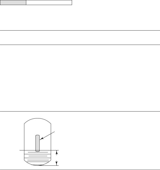
Level Offset is the value DLC3100 reports when the process level is at the bottom of the displacer. Adding a level offset permits the process variable value in engineering units to be reported with respect to a reference point other than the bottom of the displacer. Examples include: bottom of the process vessel, the process set point, or sea level. Set Level Offset is only available in Level or Interface measurement mode. Follow the prompts on the Field Communicator to enter the offset value (2-3-2-1-6).
Level Offset will affect URV/LRV, PV Hi/Lo, PV HiHi/LoLo alerts. Changing PV alert points assumes you have already considered the affect of Level Offset on the alert points. This parameter should be cleared to zero before running Device Setup.
Figure 81. Example of the Use of Level Offset
URV |
|
|
DISPLACER |
|
|
||
(10 FEET) |
|
||
|
|
||
|
|
|
|
LRV
(6 FEET)
LEVEL
OFFSET
(6 FEET)
E0368
20
Instruction Manual |
DLC3100 Digital Level Controller |
D104213X012 |
July 2019 |
|
|
Initial Setup
Initial Setup consists of the following:
D Device Setup
D PV Setup
D Process Setup
All three setup procedures must be completed when configuring the DLC3100 in order for the device to function properly.
Initial Setup directs you through initialization of configuration data needed for proper operation. When the instrument comes out of the box, the default dimensions are set for the most common Fisher 249 construction. If any data is unknown, it is generally safe to accept the defaults. The mounting position - left or right of displacer - is important for correct interpretation of positive motion. Use Manual Setup to locate and modify individual parameters when they need to be changed. Refer to the Initial Setup section below for DLC3100 configuration.
Notes
The DLC3100 has to be “Not In Service” when carrying out Initial Setup. Place the loop into manual operation before putting device out of service as the output will not be valid.
When the DLC3100 is out of service, it is locked for exclusive access by the Primary/Secondary master that put it out of service. If the instrument reports Locked by HART or Access Restricted when you attempt to configure it, and a master of the original priority is not available, use Force Mode on the Local User Interface menu to force the instrument mode to In Service. You will then be able to take it out of service with your own master to make changes.
Guided setup is available to aid initial setup. Follow the prompts to enter information required by the setup. Most of the information is available from the sensor nameplate.
Device Setup
AMS Configure > Guided Setup > Device Setup
Field Communicator Configure > Guided Setup > Device Setup (2-2-1)
Input the required information as follows:
D Displacer Information (Length, Weight and Volume)
D Driver Rod Length (refer to table 11 and figure 9)
D Mounting Position (Left or Right of Displacer)
D 249 Sensor Model
D Torque Tube Material and wall thickness
The Driver Rod (moment arm) is the effective length of the driver rod length, and depends upon the sensor type. For a 249 sensor, refer to table 11 to determine driver rod length.
Once Device Setup is completed, configure the application settings using the PV Setup procedures.
21
DLC3100 Digital Level Controller |
|
|
Instruction Manual |
|
July 2019 |
|
|
D104213X012 |
|
|
|
|
|
|
Table 11. Driver Rod Length(1) |
|
|
|
|
SENSOR TYPE(2) |
|
MOMENT ARM |
|
|
mm |
|
Inch |
|
|
|
|
|
||
249 |
203 |
|
8.01 |
|
|
|
|
|
|
249B |
203 |
|
8.01 |
|
|
|
|
|
|
249BF |
203 |
|
8.01 |
|
|
|
|
|
|
249BP |
203 |
|
8.01 |
|
|
|
|
|
|
249C |
169 |
|
6.64 |
|
|
|
|
|
|
249CP |
169 |
|
6.64 |
|
|
|
|
|
|
249K |
267 |
|
10.5 |
|
|
|
|
|
|
249L |
229 |
|
9.01 |
|
|
|
|
|
|
249N |
267 |
|
10.5 |
|
|
|
|
|
|
249P |
203 |
|
8.01 |
|
(CL125-CL600) |
|
|
||
|
|
|
|
|
|
|
|
|
|
249P |
229 |
|
9.01 |
|
(CL900-CL2500) |
|
|
||
|
|
|
|
|
|
|
|
|
|
249VS (Special)(1) |
See serial card |
|
See serial card |
|
249VS (Std) |
343 |
|
13.5 |
|
|
|
|
|
|
249W |
203 |
|
8.01 |
|
|
|
|
|
|
1. Driver rod length is the perpendicular distance between the vertical centerline of the displacer and the horizontal centerline of the torque tube. See figure 9. If you cannot determine the driver rod length, contact your Emerson sales office and provide the serial number of the sensor.
2. This table applies to sensors with vertical displacers only. For sensor types not listed, or sensors with horizontal displacers, contact your Emerson sales office for the driver rod length. For other manufacturers' sensors, see the installation instructions for that mounting.
Figure 9. Method of Determining Moment Arm from External Measurements
VESSEL
VERTICAL CL OF
DISPLACER
MOMENT
ARM LENGTH
HORIZONTAL CL OF
TORQUE TUBE
22

Instruction Manual |
DLC3100 Digital Level Controller |
D104213X012 |
July 2019 |
|
|
PV Setup
AMS Configure > Guided Setup > PV Setup
Field Communicator Configure > Guided Setup > PV Setup (2-2-2)
PV Setup consists of the following:
D Measurement Application (Level, Interface or Density) (see table 12)
D Analog Output Action (Direct or Reverse)
D Level Offset
D Measurement Range (Lower Range Value and Upper Range Value)
Note
For interface applications, if the 249 is not installed on a vessel, or if the cage can be isolated, calibrate the instrument with weights, water, or other standard test fluid, in level mode. After calibrating in level mode, the instrument can be switched to interface mode, then enter the actual process fluid specific gravity and range values, follow with Trim Zero.
Table 12. Application Information
Measurement Application |
Description |
|
|
The default process variable units are set to the same units chosen for displacer length. When level |
|
Level, Interface |
offset is changed, range values will be initialized based on level offset and displacer length. The default |
|
upper range value is set to equal to displacer length and the default lower range value is set to zero when |
||
|
||
|
the level offset is 0. |
|
|
|
|
Density |
The default process variable units are set to “SGU” (Specific Gravity Units). The default upper range value |
|
is set to “1.0” and the default lower range value is set to ”0.1”. |
||
|
||
|
|
When a DLC3100 with analog output is set for direct action the loop current will increase as the fluid level increases. Upper Range Value is the process variable values at 20 mA and Lower Range Value is the process variable values at 4 mA.
Choosing Reverse action will swap the default values of the upper and lower range values. The loop current will decrease as the fluid level increases. Upper Range Value is the process variable values at 4 mA and Lower Range Value is the process variable values at 20 mA.
Once PV Setup is completed configure the process information using the Process Setup procedures.
Process Setup
AMS Configure > Guided Setup > Process Setup
Field Communicator Configure > Guided Setup > Process Setup (2-2-3)
Process Setup consists of the following:
D Process Temperature Input (None, Manual or RTD) (see table 13)
D Fluid Type (Water/Steam, Hydrocarbon, H2SO4 Aqueous Solution or Custom Fluid)
D Fluid Density
23
 Loading...