

Instruction Manual
Form 5007
August 2008
133 Series Self-Operated Regulators
133 Series
W1327
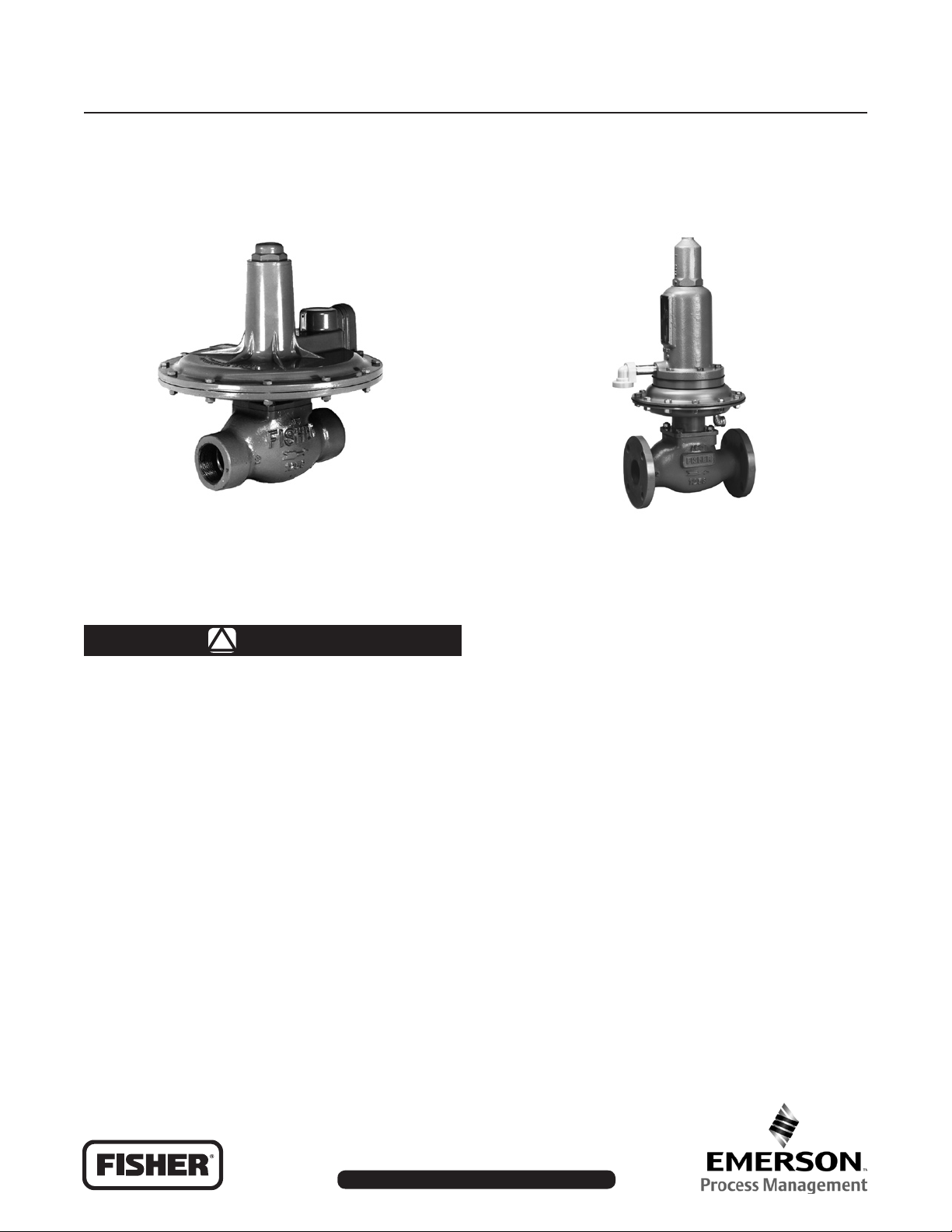
TYPES 133H, 133L, AND 133Z REGULATORS
Figure 1. 133 Series Gas Regulators
Introduction
WARNING
!
Installation, operation and maintenance
procedures performed by unqualied
personnel may result in improper
adjustment and unsafe operation. Either
condition may result in equipment
damage or personnel injury. Use qualied
personnel when installing, operating and
maintaining the 133 Series regulators.
If a leak develops in the system, the
escaping gas may accumulate and
become a re or explosion hazard.
Immediately call qualied service
personnel in case of trouble.
Scope of Manual
This manual provides specications, instructions
for installation, adjustment, maintenance, and parts
information for the 133 Series.
W6803
TYPE 133HP REGULATOR
Only personnel qualied through training or experience
should install, operate and maintain this regulator. If
there are any questions concerning these instructions,
contact your local Sales Ofce before proceeding.
Description
The 133 Series self-operated gas regulators, shown
in Figure 1 are primarily designed for industrial and
commercial applications supplying gas to furnaces,
burners and other appliances. The 133 Series
balancing system enables the regulator to provide
accurate control gas pressure for maximum combustion
efciency despite varying inlet pressure conditions. The
single port construction provides bubble tight shutoff.
An external downstream control line is required for
the operation of the regulator. A restriction collar is
available to reduce the ow capacity of the regulator.
www.emersonprocess.com/regulators
D100270X012
133 Series
Specications
End Connections
2-inch Cast iron NPT (internal), cast iron
CL125 FF anged, steel NPT (internal). or steel
CL150 RF anged
Outlet Pressure Ranges
See Table 1
Maximum Inlet Pressures
(1)
See Table 2
Maximum Outlet Pressures
See Table 2
Pressure Registration
External; downstream control line is required.
Construction Materials
Body: Cast iron or Steel
Orice and Cage: Aluminum
Valve Disk: Aluminum/Neoprene (CR)
O-Rings: Nitrile (NBR)
Diaphragms: Nitrile (NBR)/Nylon (PA)
(neoprene (CR) in actuator)
Guide Bushing: Nylon
Stem and Stem Sleeve: Stainless steel
Diaphragm Plate: Steel
Balancing Diaphragm Plate: Plated Steel
Spring Case:
Type 133 HP: Cast Iron
Types 133H, 133L, and 133Z: Aluminum
Lower Casing: Aluminum
Closing Cap: Cast iron
Adjusting Screw: Steel
Optional Restriction Collar: Aluminum
Temperature Capabilities
(1)
-20° to 150°F (-29° to 66°C)
Control Line Connection
Types 133H, 133L, and 133Z: 3/4-inch NPT
(internal); connection will be positioned directly
over body outlet (standard position) or 90 degrees
right or left of standard position if specied
Type 133HP: 1/4-inch NPT (internal) connection
positioned directly over body outlet
Vent Connection
Types 133H, 133L, and 133Z: 1-inch NPT (internal)
with screen; standard position is in line with control
line connection directly over body outlet. Vent will
always be positioned over the control line connection
Type 133HP: 1/2-inch NPT (internal) connection
positioned directly over body inlet with a Fisher®
Type Y602-7
Approximate Weight
Types 133H, 133L, and 133Z NPT End
Connections: 35 pounds (15,9 kg)
Types 133H, 133L, and 133Z Flanged End
Connections: 40 pounds (18,1 kg)
Type 133HP NPT End Connections:
56.5 pounds (25,6 kg)
Type 133HP Flanged End Connections:
62.5 pounds (28,3 kg)
1. None of the pressure/temperature limits in this Instruction Manual, nor any applicable standard limitation, should not be exceeded.
Type Number Description
Type 133H—High pressure construction for outlet
pressure range of 1.5 to 10 psig (0,10 to 0,69 bar).
The Type 133H can also use the 2-inches w.c. to
2 psig (5,00 mbar to 0,14 bar) springs of the
Type 133L. The maximum operating inlet pressure
is 60 psig (4,14 bar) with a maximum emergency inlet
pressure of 125 psig (8,62 bar).
Type 133HP—Extra high pressure construction for outlet
pressure range of 2 to 60 psig (0,14 to 4,14 bar). The
maximum operating inlet pressure rating of 150 psig
(10,3 bar) with a maximum emergency inlet pressure of
150 psig (10,3 bar).
2
Type 133L—Low pressure construction for outlet
pressure range of 2-inches w.c. to 2 psig (5,00 mbar
to 0,14 bar). The maximum operating inlet pressure
is 60 psig (4,14 bar) with a maximum emergency inlet
pressure of 125 psig (8,62 bar).
Type 133Z—Zero governor construction for outlet
pressure range of -1 to 4-inches w.c. (-2,00 to
10,00 mbar). The maximum operating inlet pressure is
20 psig (1,38 bar) with a maximum emergency inlet
pressure of 125 psig (8,62 bar).
133 Series
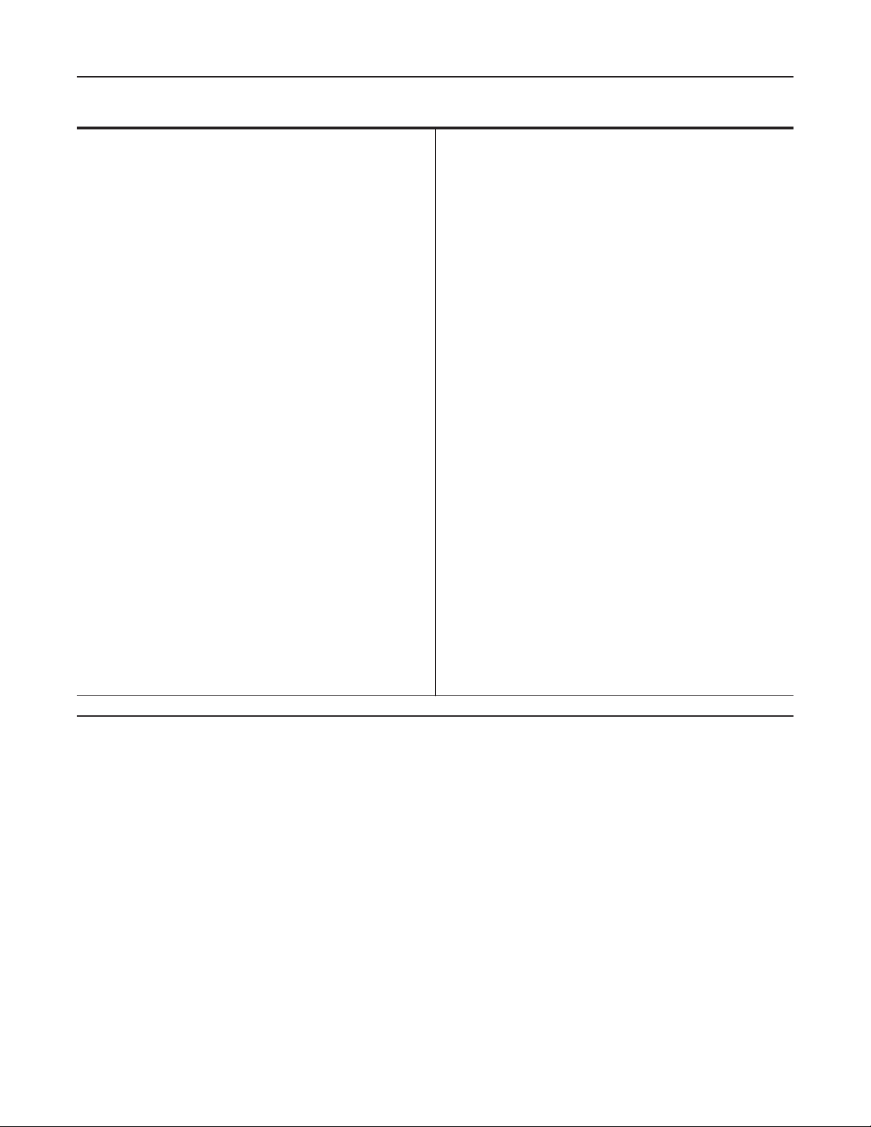
INLET PRESSURE
OUTLET PRESSURE
ATMOSPHERIC PRESSURE
BOOST PRESSURE
INLET PRESSURE
OUTLET PRESSURE
ATMOSPHERIC PRESSURE
BOOST PRESSURE
A6555
Figure 2. Operational Schematic of Type 133L Regulator (Also Typical of Type 133H)
Principle Operation
Refer to the operational schematics in Figures 2 and 3.
In the 133 Series, downstream pressure is registered
under the diaphragm via the external control line and
is used as the operating medium. Increased demand
lowers the downstream pressure and allows the spring
to move the diaphragm and stem assembly down,
opening the valve disk and supplying more gas to the
downstream system. Decreased demand increases
the downstream pressure and moves the diaphragm
and stem assembly up, closing the valve disk and
decreasing the gas supply to the downstream system.
Boosting System
The 133 Series incorporates a balancing diaphragm
and a boosting system. When the regulator is locked
up, inlet pressure is registered on the top of the valve
disk and on the bottom of the balancing diaphragm
through registration holes in the top of the cage. Also,
downstream pressure is registered on the bottom
of the valve disk and on the top of the balancing
diaphragm through a passage formed by grooves in
the registration disk and an annular space between the
stem and stem sleeve.
When the valve disk is open, gas ows from the inlet
over the edge of the valve disk to the outlet. Under
the valve disk near the registration disk, there is little
gas ow. The gas pressure near the registration disk
is higher than it is in the ow path where gas velocity
tends to lower the pressure. The higher pressure
near the disk is registered on the top of the balancing
diaphragm through the registration disk and the
annular space between the stem and stem sleeve.
This pressure registered on the top of the balancing
diaphragm aids downward disk travel and
compensates for spring and diaphragm effect. This
improves regulator range ability and performance.
3
133 Series
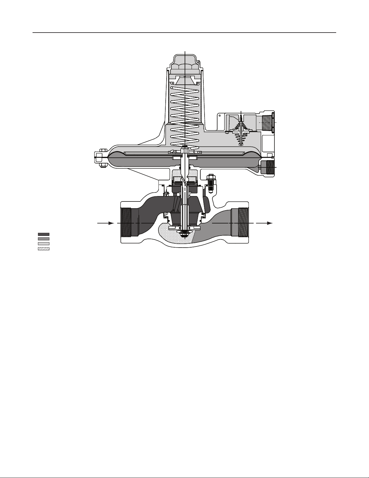
Type 133HP
Type 133HP
INLET PRESSURE
OUTLET PRESSURE
ATMOSPHERIC PRESSURE
overpressure protection is needed if the actual inlet
pressure exceeds the outlet pressure rating.
Maximum operating inlet pressure for the 133 Series
regulators is given in Table 2. All models must
be protected against inlet pressure above their
listed maximum.
Regulator operation below these emergency pressure
limitations does not preclude the possibility of damage
from external sources or from debris in the gas line.
The regulator should be inspected for damage after
any overpressure condition.
Downstream Control Line
An external downstream control line must be installed
before putting the 133 Series regulators in operation.
Without the control line, the regulator will remain wideopen. The downstream control line should be a pipe of
at least 1/2-inch (12,7 mm) diameter; connect it to the
downstream pipe line at least 5 to 10 pipe diameters
from the regulator and in a straight section of pipe.
INLET PRESSURE
OUTLET PRESSURE
ATMOSPHERIC PRESSURE
A6883
Figure 3. Operational Schematic of Type 133HP
Installation
Before installing the 133 Series regulators, inspect it
for shipping damage and be certain that the body and
orice are clean. Blow out the pipeline to remove pipe
scale and other foreign material.
The regulator may be installed in any position as long
as the ow through the body is the same as indicated
by the ow direction arrow on the body and the vent
opening is unobstructed and protected from the
entrance of rain, ice and other foreign material.
If the regulator has threaded end connections, coat
male threads with pipe compound. For anged
end connections, tighten the ange bolts evenly.
Install a three valve bypass around the 133 Series if
continuous operation is necessary.
The regulator must be protected from damage by
vehicles and other outside sources.
Overpressure Protection
The 133 Series regulators, as is the case with most
regulators, has an outlet pressure rating that is
lower than the inlet pressure rating. Some type of
The external downstream control line connection on
the Type 133HP is 1/4-inch threaded NPT.
Vent
The 133 Series vent is screened to prevent insects
or foreign material from entering. On indoor
installations, if a vent to atmosphere is required,
remove the snap ring and screen (keys 8J and 8H;
Figure 10, 11, or 12) from the Types 133H, 133L, and
133Z. Remove the Type Y602-7 screened vent and
pipe nipple (keys 50 and 49; Figure 14) from
the spring case (key 8) and pipe the vent to the
outside. The Types 133H, 133L, and 133Z have
a 1-inch NPT (internal) connection and the Type 133HP
has a 1/2-inch NPT (internal) construction.
The vent pipe should be as short as possible with
a minimum of bends and elbows. The pipe should
also have as large a diameter as possible. Install
a weather and bug resistant vent assembly on the
outside end of the vent pipe.
For indoor installation that have been piped to the
outside and for outdoor installations, the vent opening
must be positioned so that water, ice and other foreign
material cannot enter the spring case. Use care not to
place the vent opening below downspouts and eaves.
The vent opening should be checked periodically to
see that the opening has not been plugged by foreign
material. On some installations it may be necessary to
provide additional protection from the elements.
4
133 Series
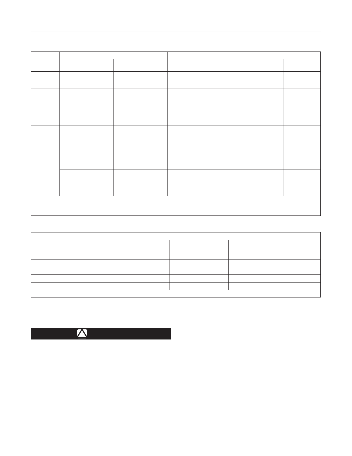
Table 1. 133 Series Outlet Pressure Ranges, Control Springs
OUTLET PRESSURE RANGE CONTROL SPRINGS
TYPE
(1)
133H
(1)
133HP
(1)
133L
and
(2)
133H
(1)
133Z
1. Pressure ranges shown are correct if the regulator is installed with the actuator portion above the body portion. If the regulator is installed with the actuator portion below the body,
the pressure ranges will be lowered by approximately 2-inches w.c. (5,00 mbar) for the Type 133L and by approximately 3-inches w.c. (7,00 mbar) for the Types 133H and 133Z.
2. If the 2-inches w.c. to 2 psig (5,00 mbar to 0,14 bar) springs (all 6 ranges) are used in the Type 133H, the pressure ranges will increase by approximately 1-inch w.c. (2,00 mbar) due
to the weight of the Type 133H parts (assuming that the actuator is installed above the body).
Inches w.c./Psig bar/mbar Part Number
1.5 to 3 psig
2 to 5 psig
5 to 10 psig
2 to 5 psig
4.5 to 10 psig
6 to 20 psig
16 to 30 psig
26 to 40 psig
36 to 50 psig
45 to 60 psig
2 to 4-inches w.c.
3.5 to 6-inches w.c.
5 to 9-inches w.c.
8.5 to 18-inches w.c.
14 to 28-inches w.c.
0.75 to 2 psig
-1 to 1-inch w.c. -2,00 to 2,00 mbar
0 to 4-inches w.c. 0 to 10,00 mbar
0,10 to 0,21 bar
0,14 to 0,34 bar
0,34 to 0,69 bar
0,14 to 0,34 bar
0,31 to 0,69 bar
0,41 to 1,38 bar
1,10 to 2,07 bar
1,79 to 2,76 bar
2,48 to 3,45 bar
3,10 to 4,14 bar
5,00 to 10,00 mbar
9,00 to 15,00 mbar
12,00 to 22,00 mbar
21,00 to 45,00 mbar
35,00 to 70,00 mbar
0,05 to 0,14 bar
1H975927032
10A9440X012
1J146927142
17B8632X012
17B8633X012
10C1238X012
10C1240X012
10C1241X012
10C1242X012
10C1243X012
1D892527022
1D892627022
1D892727012
1D893227032
1D893327032
1H975827032
1K633427012
(Extension Spring)
1K633427012
(Extension Spring)
1D892527022
(Composition Spring)
and
Color Code
Stripe
Orange
Yellow
Blue
Yellow
Orange
Silver
Red
Blue
Green
White
Brown
Red
Black
White
Green
Blue
Black 2 (50,80) 0.075 (1,91)
Black
Brown
Free Length,
Inch (mm)
7-3/8 (187)
6-15/32 (164)
6-3/16 (157)
8-1/2 (216)
8-1/2 (216)
8-1/4 (210)
8-1/4 (210)
8-1/4 (210)
8-1/4 (210)
8-1/4 (210)
6-1/8 (156)
7-1/2 (190)
7-7/8 (200)
7-1/2 (190)
7-1/4 (184)
7-3/8 (187)
2 (50,80)
6-1/8 (156)
Wire Diameter,
Inch (mm)
0.250 (6,35)
0.283 (7,19)
0.375 (9,53)
0.281 (7,14)
0.343 (8,71)
0.406 (10,31)
0.500 (12,70)
0.500 (12,70)
0.531 (13,49)
0.225 (5,72)
0.109 (2,77)
0.120 (3,05)
0.130 (3,30)
0.156 (3,96)
0.182 (4,62)
0.225 (5,72)
0.075 (1,91)
0.109 (2,77)
Table 2. Maximum Inlet and Outlet Pressures
TYPE NUMBER
PRESSURES
Maximum Operating Inlet Pressure 60 (4,14) 150 (10,34) 60 (4,14) 20 (1,38)
Maximum Emergency Inlet Pressure 125 (8,62) 150 (10,34) 125 (8,62) 125 (8,62)
Maximum Operating Outlet Pressure
Maximum Outlet Pressure Over Outlet Pressure Setting 3 (0,21) - - - - 3 (0,21) 3 (0,21)
Maximum Emergency Outlet (Casing) Pressure 15 (1,03) 150 (10,34) 15 (1,03) 15 (1,03)
1. With highest spring range available only.
(1)
Startup
133H
Psig (bar)
10 (0,69) Setpoint Plus 40 psi (2,76) 2 (0,14) 4-inches w.c. (10,00 mbar)
133HP
Psig (bar)
133L
Psig (bar)
133Z
Psig (bar)
setting by more than 3 psig (0,21 bar), or
the valve seat or diaphragm plates can be
damaged. The procedure used in putting
WARNING
!
the regulator in service must be planned
accordingly. Pressure gauges should
If the downstream system is already
pressured by another regulator or by a
manual bypass, then extra precautions
must be taken when placing the 133 Series
in service. The outlet of the regulator
must never be subjected to pressures
higher than the inlet pressure, or the
balancing diaphragm may be damaged.
Also, the control line pressure must never
exceed the set point dictated by the spring
always be used to monitor downstream
and control line pressures during startup.
If the downstream system is not pressured by
another regulator or by manual bypass, use the
following procedure.
1. Slowly open the upstream shutoff valve.
2. Slowly open the downstream shutoff valve.
3. Check all connections for leaks.
5
 Loading...