

Page 1
Product Bulletin
1080 Manual Actuator
D500238X012
22.2:1080
January 2013
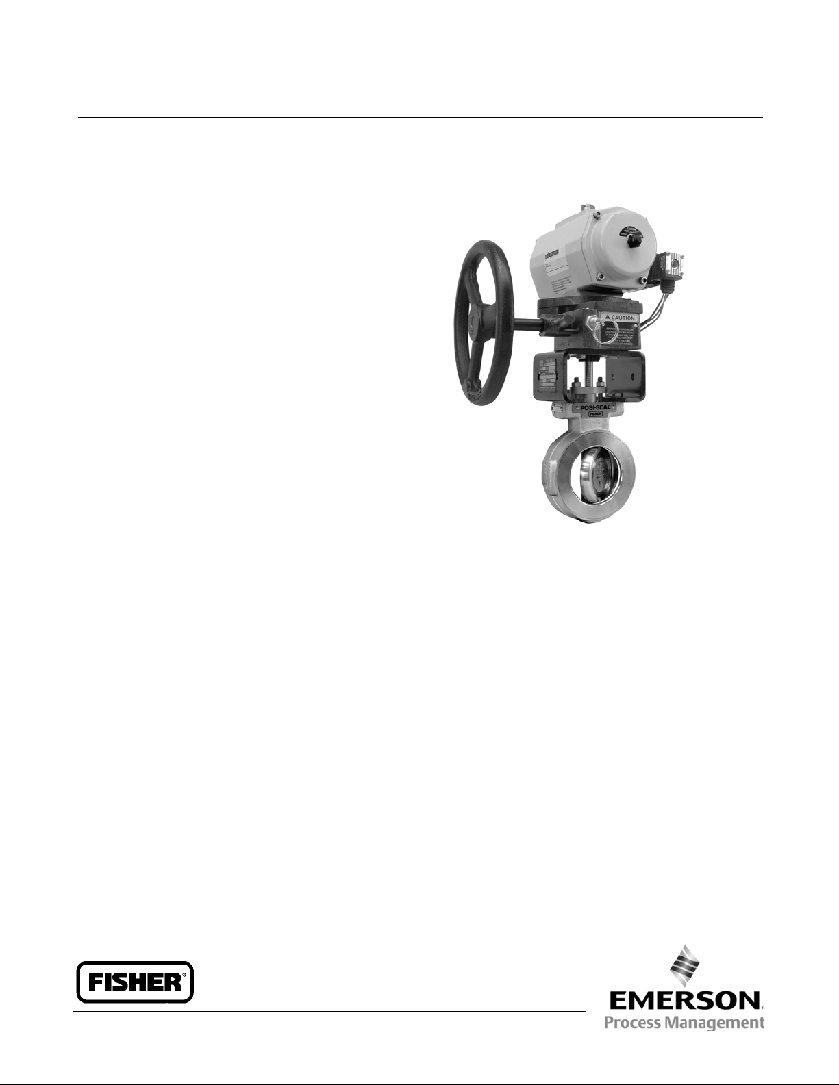
Fisherr 1080 Declutchable Manual Actuator
The Fisher 1080 manual actuator is a Declutchable
Actuator for manual operation of A41 double D shaft
control valves that use a 1035/El-O-Matic power
actuator. As shown in the following figure, the 1080
manual actuator mounts directly on the 1035
actuator. It can be engaged to allow manual operation
of the valve when the power actuator is not in use or
disengaged to allow automatic operation of the valve
by the power actuator.
Features
Direct Attachment to the Power Actuator– Direct
mounting to the actuator housing simplifies
installation and eliminates the need for additional
mounting parts.
Engage Manual Actuator At Any Point of Rotation–
A lever-operated eccentricbearingsupportonthe
input shaft allows engagement of the worm gear
with the sector at any point of rotation.
Simplified Selection– Each size of the 1080
corresponds to the capabilities of a size of the 1035.
So you need only calculate the size of the 1035,
when ordering both a 1035 and 1080 (see table 1).
W9256
Fisher 1080 Manual Actuator Mounted on a
1035/El-O-Matic Actuator
Positive Operation– The disengagement lever is
held in both the engaged and disengaged positions
by a spring-loaded pin, which must be released
before the lever can be moved. This reduces the
possibility of inadvertent or accidental operation. In
addition, stop-pins at the fully engaged and fully
disengaged positions provide positive limits for
lever travel.
www.Fisher.com
Page 2
Product Bulletin
22.2:1080
January 2013
Specifications
1080 Manual Actuator
D500238X012
Available Configurations
Direct acting; see Handwheel Rotation
Manual Actuator Sizes
See table 1
PowerActuatorCompatibility
Compatible with all sizes of 1035 actuator; see table 1
Maximum Torque Output
See table 1, Wheel-Rim Force
Handwheel Rotation
Clockwise handwheel rotation closes valve (produces
clockwise valve shaft rotation)
Construction Materials
Housing and Cover: Cast iron
Drive Sleeve/Gear (Sector): Low-carbon steel/bronze
Worm Gear: Heat-treated steel
Input Shaft and Eccentric: Low-carbon steel/bronze
Pin Detent: 300 Series stainless steel
Shaft Bearings: Bronze
Mounting Positions (see figure 1)
J Standard mounting is with the input shaft
perpendicular to the 1035 actuator piston travel, with
the handwheel opposite the actuator supply
connections;
handwheel on the same side as the 1035 actuator
supply connections
Dimensions
Seefigure2
Approximate Weight without Handwheel
Size AAA: 5.4 kg (12 lb)
Size AA: 10 kg (22 lb)
Size A: 14 kg (31 lb)
Size B: 22 kg (49 lb)
Size C: 34 kg (76 lb)
Size D: 52 kg (115 lb)
Size F: 68 kg (150 lb)
Handwheel Weight
8-inch: 2.0 kg (4.50 lb)
12-inch: 4.0 kg (6.75 lb)
16-inch: 6.8 kg (15.00 lb)
24-inch: 5.4 kg (12.00 lb)
30-inch: 6.8 kg (15.00 lb)
36-inch: 7.8 kg (17.25 lb)
J optional mounting is with the
Ordering Information
Each size of the 1080 corresponds to a specific size of
1035 as shown in table 1. The torque output of the
1080 actuator is matched to the capabilities of the
1035 power actuator.
The1080actuatorcanhandletheSpringReturn1035
actuatortorquesaswellastheDoubleActing1035
actuator,becausetheDoubleActingtorqueat100
psig is approximately equal to the sum of both the
Spring Return spring start torque and the Spring
Return air end torque at 100 psig.
An optional bypass valve should be ordered for use on
a 1035 actuator if you plan to engage the manual
actuator while the power actuator has air pressure
applied to it. For activation of the 1080, air pressure
mustnotbetrappedinthe1035ormustbeequalized
between the pistons by a bypass valve.
2
Page 3

1080 Manual Actuator
D500238X012
Product Bulletin
22.2:1080
January 2013
Table1.ActuatorSizeSelection and Specifications
ACTUATOR
SIZE
AAA/S1 E25
AAA/S2
AAA/S3 E100 132 1,168 218 49
AA/S4
A/S4 E600 32:1 8
B/S5 E950 40:1 10 1,356 12,000 1,290 11,300 271 61
C/S6 E1600 54:1 13.5 762 30 2,034 18,000 2,140 18,600 298 67
D/SQ3 P2500 64:1 16 914 36 3,390 30,000 3,377 29,891 383 86
F/SQ4 P4000 282:1 70.5 406 16 6,779 60,000 5,701 50,458 334 75
1. Only the 1080/1035 combinations shown are available.
2. Maximum torque output of the 1080 actuatoronly.
3. Torque output of the 1035 actuator at100 psig and required 1080 torque output for use with the 1035.
4. Amount of force necessary at rim ofthe handwheel to matchtorque output of the 1035 at 100psig.
1035
ACTUATOR
SIZE
E40
E65
E200
E350
GEAR
RATIO
24:1 6 203 8 271 2,400
34:1 8.5 305 12 542 4,800
NUMBER OF
TURNS TO
CLOSE
(1)
HANDWHEEL
DIAMETER
mm Inches NSm lbSin NSm lbSin N lbf
610 24
1080 MAXIMUM
926 8,200 866 7,550 276 62
TORQUE
(2)
1035 TORQUE
31 274 49 11
58
89
289
502
513
788
2,558
4,443
WHEEL RIM FORCE
(3)
FOR MAXIMUM
TORQUE
93
147
222
387
Figure 1. Fisher 1080 Actuator Mounting Positions
1080
HANDWHEEL
FLOW
DIRECTION
FOR LEFT-HAND
MOUNTING
FLOW DIRECTION
FORRIGHT-HAND
MOUNTING
1080 HANDWHEEL
FLOW DIRECTION
FOR LEFT-HAND
MOUNTING
1035 PRESSURE
PORTS
FLOW DIRECTION
FORRIGHT-HAND
MOUNTING
(4)
21
33
50
87
1035 PRESSURE PORTS
FOR USE WITH 1035 ACTUATOR ALL SIZES
FLOW DIRECTION
FORRIGHT-HAND
MOUNTING
MOUNTING POSITION 1
(STANDARD)
1035 PRESSURE PORTS
FLOW DIRECTION
FOR LEFT-HAND
MOUNTING
FOR USE WITH 1035 ACTUATOR SIZES E25 THRU E350 AND P4000
NOT AVAILABLE FOR 1035 ACTUATOR SIZES E600 THRU E1600 AND P2500
MOUNTING POSITION 2
FLOW DIRECTION
FORRIGHT-HAND
MOUNTING
1080
HANDWHEEL
1080 HANDWHEEL
FOR USE WITH 1035 ACTUATOR ALL SIZES
MOUNTING POSITION 3
75B0768
B2702
Note:
Right-andleft-handmountingisbasedontheA41valvedriveshaftbeingmountedintherecommendedhorizontalposition.
FOR USE WITH 1035 ACTUATORSIZES E25 THRU E350 AND P4000
NOT AVAILABLE FOR 1035 ACTUATOR SIZES E600 THRU E1600 ANDP2500
MOUNTING POSITION 4
FLOW DIRECTION
FOR LEFT-HAND
MOUNTING
1035
PRESSURE PORTS
3
Page 4

Product Bulletin
22.2:1080
January 2013
Table 2. Dimensions
1080
Actuator
Size
AAA/S1 E25 203 191 68 30 73 132 153 55 46 51 50
AAA/S2 E40, E65 203 191 68 30 73 132 153 55 46 51 70
AAA/S3 E100 203 191 68 30 73 132 153 55 46 51 70
AA/S4 E200, E350 305 210 89 29 83 181 216 94 59 64 102
A/S4 E600 610 381 105 32 89 337 378 238 67 73 125
B/S5 E950 610 381 114 41 105 346 394 222 83 89 140
C/S6 E1600 762 406 143 44 117 425 492 276 105 111 165
D/SQ3 P2500 914 427 171 67 168 524 583 338 119 125 165
F/SQ4 P4000 406 451 171 162 168 365 441 178 127 137 165
AAA/S1 E25 8 7.50 2.69 1.188 2.88 5.19 6.03 2.18 1.83 2.03 1.969
AAA/S2 E40, E65 8 7.50 2.69 1.188 2.88 5.19 6.03 2.18 1.83 2.03 2.756
AAA/S3 E100 8 7.50 2.69 1.188 2.88 5.19 6.03 2.18 1.83 2.03 2.756
AA/S4 E200, E350 12 8.25 3.50 1.126 3.25 7.13 8.50 3.69 2.31 2.50 4.016
A/S4 E600 24 15.00 4.13 1.253 3.50 13.25 14.88 9.38 2.63 2.88 4.921
B/S5 E950 24 15.00 4.50 1.625 4.12 13.62 15.50 8.75 3.25 3.50 5.512
C/S6 E1600 30 16.00 5.62 1.750 4.62 16.75 19.38 10.88 4.12 4.38 6.496
D/SQ3 P2500 36 16.81 6.75 2.630 6.63 20.63 22.94 13.31 4.69 4.94 6.496
F/SQ4 P4000 16 17.75 6.75 6.380 6.63 14.38 17.38 7.00 5.00 5.38 6.496
1035
Actuator
Size
J HW M D DW EW FD GE NE ND
mm
Inches
1080 Manual Actuator
D500238X012
KW Bolt
Circle
Diameter
Figure 2. Dimensions (also see table 2)
HW
DISENGAGED
18B6626-D
E0720
J
ENGAGED
KW
Neither Emerson, Emerson Process Management,nor any of their affiliated entitiesassumes responsibility for the selection, use or maintenance
of anyproduct. Responsibility for proper selection, use, and maintenance ofany productremains solely with the purchaser and end user.
Fisher isa mark owned by one of thecompanies in the Emerson Process Management business unit of Emerson Electric Co. Emerson Process Management,
Emerson, and the Emerson logoare trademarks and service marks of Emerson Electric Co. All other marks are the property of their respective owners.
The contents of this publication are presented for informational purposes only, and while every effort has been made to ensure their accuracy, they arenot
to be construed as warranties or guarantees, express or implied, regarding the products or services described herein or their use or applicability. All sales are
governed by our terms and conditions, which are available upon request.We reservethe rightto modifyor improvethe designs or specifications ofsuch
products at any time without notice.
Emerson Process Management
Marshalltown, Iowa 50158 USA
Sorocaba, 18087 Brazil
Chatham, Kent ME4 4QZ UK
Dubai, United Arab Emirates
Singapore 128461 Singapore
www.Fisher.com
M
GE
ENGAGED
NE
ENGAGED
FD
DISENGAGED
ND
DISENGAGED
EW
DW
CENTER LINE
OF ACTUATOR
D
E 1998, 2013 Fisher ControlsInternational LLC. All rights reserved.
4
 Loading...