

Page 1
Product Bulletin
1079 Manual Actuator
D500209X012
22.2:1079
January 2013
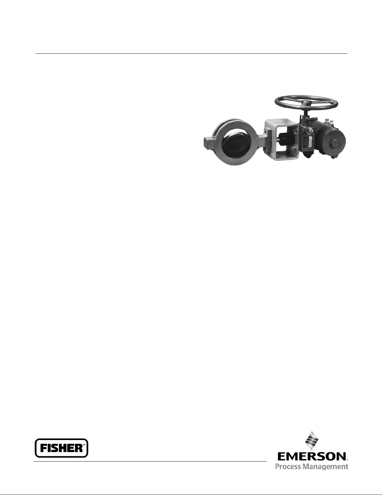
Fisherr 1079 Declutchable Manual Actuator
The 1079 manual actuator is a declutchable unit for
manual operation of keyed or square shaft control
valves and equipment that use a Hytork actuator. The
1079 manual actuator mounts directly on the Hytork
actuator and can be engaged to allow manual
operation of the valve when the power actuator is not
in use or disengaged to allow automatic operation of
the valve by the power actuator. The mechanism used
allows manual actuator engagement at any point of
poweractuatorrotation.
W6214
Fisher 1079 Manual Actuator Mounted on a
Hytork Actuator and A41 Valve
Features
Direct Attachment to the Power Actuator-- Direct
mounting to the actuator housing simplifies
installation and eliminates the need for yokes and
other brackets.
Engage Manual Actuator At Any Point of Rotation--
A lever-operated eccentricbearingsupportonthe
input shaft allows engagement of the worm gear
with the sector at any point of rotation.
Positive Operation-- The disengagement lever is
held in both the engaged and disengaged positions
by a spring-loaded pin, which must be released
before the lever can be moved. This reduces the
possibility of inadvertent or accidental operation. In
addition, stop-pins at the fully engaged and fully
disengaged positions provide positive limits for
lever travel.
www.Fisher.com
Page 2
Product Bulletin
22.2:1079
January 2013
Specifications
1079 Manual Actuator
D500209X012
Available Configurations
Direct acting; see Handwheel Rotation
Manual Actuator Sizes
See tables 1, 2, and 3
PowerActuatorCompatibility
Compatible with all sizes of Hytork actuator; see
tables 1, 2, and 3
Maximum Torque Output
See tables 1, 2, and 3
Wheel-Rim Force
See tables 1, 2, and 3
Handwheel Rotation
Clockwise handwheel rotation closes valve (produces
clockwise valve shaft rotation, as viewed from the
actuator end of the shaft)
Construction Materials
Housing and Cover: Cast iron
Drive Sleeve/Gear (Sector): Low-carbon steel/bronze
Worm Gear: Heat-treated steel
Input Shaft and Eccentric: Low-carbon steel
Pin Detent: 300 Series stainless steel
Shaft Bearings: Bronze
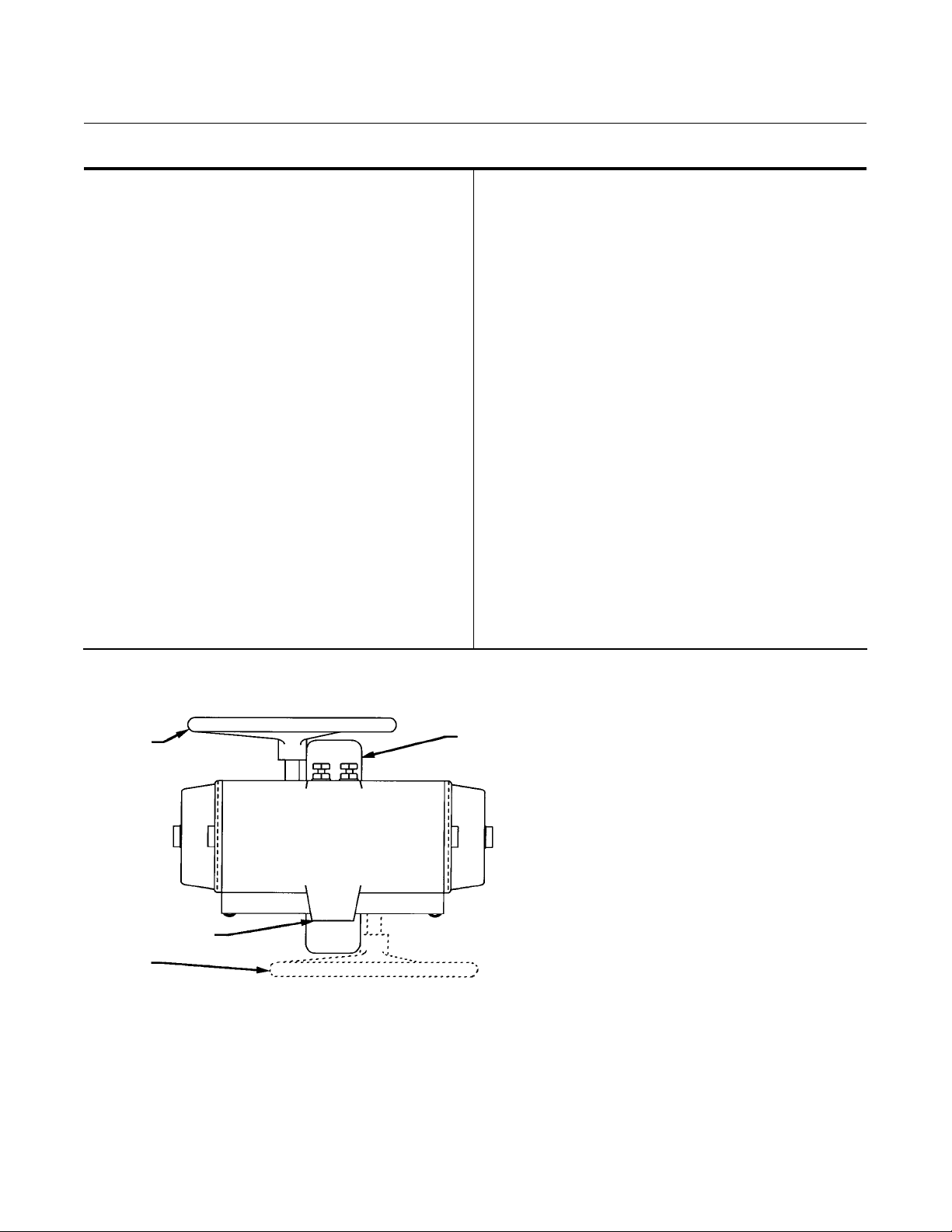
Standard Mounting Positions (see figure 1)
J Standard mounting is with the input shaft
perpendicular to the Hytork piston travel, with the
handwheel opposite the actuator supply c onnections;
J Optional mounting is with the handwheel on the
same side as the Hytork actuator supply connections
Approximate Weight without Handwheel
Size AAA: 7.3 kg (16 lb)
Size AA: 10 kg (22 lb)
Size A: 14 kg (31 lb)
Size B: 16 kg (35 lb)
Size C: 24 kg (52 lb)
Size D: 33 kg (72 lb)
Handwheel Weight
6-inch: 1.0 kg (2.25 lb)
8-inch: 2.0 kg (4.50 lb)
12-inch: 4.0 kg (8.75 lb)
24-inch: 5.4 kg (12.00 lb)
30-inch: 6.7 kg (14.75 lb)
36-inch: 7.8 kg (17.25 lb)
Figure 1. Fisher 1079 Actuator Mounting Positions
STANDARD
MOUNTING
POSITION
HYTORK ACTUATOR
SUPPLY CONNECTIONS
OPTIONAL MOUNTING
POSITION
A6186
SEAL RETAINER
SIDE OF VALVE
2
Page 3

Product Bulletin
1079 Manual Actuator
D500209X012
Table1.ActuatorSizeSelectionandSpecifications for Keyed Shaft Valves (Fisher A31A)
MAXIMUM
ALLOWABLE
TORQUE
245
271
129
245
542
542
542
542
542
129
245
671
834
926
926
926
671
834
927
1171
1233
1582
1582
1582
1582
671
834
927
1171
1233
2203
2530
2568
2712
927
1171
1233
2203
2530
2568
4067
4067
(2)
2165
2400
1145
2165
4800
4800
4800
4800
4800
1145
2165
5941
7383
8200
8200
8200
5941
7383
8205
10,360
10,911
14,000
14,000
14,000
14,000
5941
7383
8205
10,360
10,911
19,494
22,396
22,728
24,000
8205
10,360
10,911
19,494
22,396
22,728
36,000
36,000
WHEEL-RIM FORCE FOR
(3)
(3)
(3)
(3)
(3)
(3)
(3)
(3)
(3)
(3)
(3)
(3)
(3)
(3)
(3)
(3)
ACTUATOR
SIZE
HYTORK
ACTUATOR
SIZE
GEAR
RATIO
HANDWHEEL
DIAMETER
mm Inches mm Inches NSm lbfSin N lbf
VALVE SHAFT
DIAMETER
(1)
203 8 14.3 0.5625 129 1145 214 48
AAA 70 thru280 24:1
305 12
203 8
AA 70 thru280 24:1
305 12
A 680A 40:1 610 24
B 1125 40:1 610 24
610 24
C 1370 54:1
762 30
610 24
D 2585 & 4580 64:1
762 30
914 36
1. Shaft diameter at the keyway.
2. Unless otherwisenoted, torque is limited by S17400 stainless steel (17-4PH H1025) shaft material at 38_C (100_F). For other shaftmaterials, consult your Emerson Process Management
sales office.
3. Maximum manual actuator output.
4. NPS 12 CL150 A31A and NPS 8 CL300 A31A.
17.5
23.8
14.3
17.5
23.8
28.6
30.2
31.8
41.3
14.3
17.5
23.8
28.6
30.2
31.8
41.3
23.8
28.6
31.8
30.2
31.8
38.1
41.3
44.5
47.6
23.8
28.6
31.8
30.2
31.8
38.1
41.3
44.5
47.6
31.8
30.2
31.8
38.1
41.3
44.5
47.6
57.2
0.6875
0.9375
0.5625
0.6875
0.9375
1.125
1.1875
1.25
1.625
0.5625
0.6875
0.9375
1.125
1.1875
1.25
1.625
0.9375
1.125
1.25
1.1875
1.25
1.5
1.625
1.75
1.875
0.9375
1.125
1.25
1.1875
1.25
1.5
1.625
1.75
1.875
1.25
1.1875
1.25
1.5
1.625
1.75
1.875
2.25
(4)
(4)(5)
(4)
(5)
(4)
(5)
(4)
(5)
22.2:1079
January 2013
MAXIMUM TORQUE
267
298
151
298
418
418
418
418
418
44
80
222
276
302
302
302
182
227
254
320
338
431
431
431
431
138
169
187
236
249
445
409
418
440
160
200
209
378
347
351
463
463
60
67
34
64
94
94
94
94
94
10
18
50
62
68
68
68
41
51
57
72
76
97
97
97
97
31
38
42
53
56
100
92
94
99
36
45
47
85
78
79
104
104
3
Page 4

Product Bulletin
22.2:1079
January 2013
Table2.ActuatorSizeSelectionandSpecifications for Valves (Fisher A41)
ACTUATOR
SIZE
AAA 70 thru280 24:1
AA 70 thru 280 24:1
A 680A 40:1 610 24
B 1125 40:1 610 24
C 1370 54:1
D
1. Shaft diameter at packing box.
2. Unless otherwisen oted, torque is limited by S17400 (17-4 PH H1025) stainless steel shaft. For othershaft materials, contact yo ur Emerson Process Management sales office.
3. Maximum manual actuator output. For AAA, C, and D, themaximum output is 2400, 24000, and 36000 in-lb, respectively.
HYTORK
ACTUATOR
SIZE
2585 &
4580
GEAR
RATIO
64:1
HANDWHEEL DIAMETER
mm Inches mm Inches NSm lbfSin N lbf
152 6
203 8 15.9 0.625 138 1225 229 51
305 12 15.9 0.625 138 1225 152 34
152 6
203 8 19.1 0.750 240 2120 392 88
203 8
305 12
610 24
762 30 44.5 1.750 2658 23524 433 97
610 24
762 30 44.5 1.750 2658 23524 365 82
VALVE SHAFT
DIAMETER
12.7
15.9
12.7
15.9
19.1
25.4
31.8
31.8
38.1
19.1
25.4
31.8
38.1
31.8
38.1
44.5
31.8
38.1
31.8
38.1
(1)
0.500
0.625
0.500
0.625
0.750
1.000
1.250
1.250
1.500
0.750
1.000
1.250
1.500
1.250
1.500
1.750
1.250
1.500
1.250
1.500
MAXIMUM ALLOWABLE
58
138
58
138
240
468
542
542
542
240
468
926
926
1110
1356
1582
1110
1356
1110
1356
1079 Manual Actuator
TORQUE
(2)
515
1225
515
1225
2120
4140
4800
4800
4800
2120
4140
8200
8200
9820
12000
14,000
9820
12000
9820
12000
WHEEL-RIM FORCE FOR
MAXIMUM TORQUE
127
305
127
305
280
(3)
(3)
(3)
(3)
(3)
(3)
546
629
418
418
78
153
303
303
303
371
431
227
278
190
231
D500209X012
29
69
29
69
63
123
141
94
94
18
34
68
68
68
83
97
51
63
43
52
4
Page 5

Product Bulletin
1079 Manual Actuator
D500209X012
Table3.ActuatorSizeSelectionandSpecifications for Square Shaft Valves (Fisher A11)
ACTUATOR
SIZE
AAA 70 thru280 24:1
AA 70 thru 280 24:1
A 680A 40:1 610 24
B 1125 40:1 610 24
C 1370 54:1
D
1. Shaft diameter at square connection.
2. Unless otherwiseno ted, torque is limitedby S17400 stainless steel (17-4 PH H1025) shaft material at 38_C (100_F). Forother shaft materials, consult your Emerson Process Management
sales office.
3. Maximum manual actuator output.
HYTORK
ACTUATOR
SIZE
2585 &
4580
GEAR
RATIO
64:1
HANDWHEEL DIAMETER
mm Inches mm Inches NSm lbfSin N lbf
203 8 10.3 0.40625 89 790 147 33
305 12 15.9 0.625 271 2400
203 8 10.3 0.40625 89 790 102 23
305 12
610 24
762 30
610 24
914 36
VALVE SHAFT
DIAMETER
15.9
22.2
15.9
22.2
25.4
15.9
22.2
25.4
34.9
34.9
15.9
22.2
25.4
34.9
34.9
15.9
22.2
25.4
34.9
34.9
(1)
0.625
0.875
0.625
0.875
1
0.625
0.875
1
1.375
1.375
0.625
0.875
1
1.375
1.375
0.625
0.875
1
1.375
1.375
MAXIMUM ALLOWABLE
318
542
318
782
926
318
782
1351
1582
1582
318
782
1351
2712
2712
318
782
1351
3520
3520
TORQUE
(2)
2813
4800
2813
6922
8200
2813
6922
11,956
14,000
14,000
2813
6922
11,956
24,000
24,000
2813
6922
11,956
31,157
31,157
(3)
(3)
(3)
(3)
(3)
(3)
(3)
WHEEL-RIM FORCE FOR
MAXIMUM TORQUE
22.2:1079
January 2013
298 67
245
418
102
254
302
85
214
369
431
431
67
160
276
440
440
53
133
231
400
400
55
94
23
57
68
19
48
83
97
97
15
36
62
99
99
12
30
52
90
90
5
Page 6

Product Bulletin
22.2:1079
January 2013
Figure 2. Dimensions (also see table 4)
HW M
NE
ENGAGED
GE
ENGAGED
1079 Manual Actuator
D500209X012
EW
CL OF
ACTUATOR
J
13B8871-B
A6259
KW
ND
DISENGAGED
FD
DISENGAGED
DW
6
Page 7

Product Bulletin
1079 Manual Actuator
D500209X012
Table 4. Dimensions (also see figure 2)
1079
Actuator
Size
AAA 45 152 184 67 73 106 128 30 46 52 35 SQ
AAA 45 203 184 67 73 132 153 55 46 52 35 SQ
AAA 45 305 184 67 73 183 204 106 46 52 35 SQ
AAA 70-280 152 184 67 73 106 128 30 46 52 50 SQ
AAA 70-280 203 184 67 73 132 153 55 46 52 50 SQ
AAA 70-280 305 184 67 73 183 204 106 46 52 50 SQ
AA 425A 203 203 90 78 130 165 43 59 64 72 SQ
AA 425A 305 203 90 78 181 216 94 59 64 72 SQ
A 680A 610 381 105 89 337 378 238 67 73 72 SQ
B 1125 610 381 108 105 346 394 222 83 89 88 SQ
C 1370 610 406 143 117 349 416 200 105 111 88 SQ
C 1370 762 406 143 117 425 492 276 105 111 88 SQ
D
D
D
AAA 45 6.00 7.25 2.62 2.88 4.19 5.03 1.17 1.83 2.03 1.39 SQ
AAA 45 8.00 7.25 2.62 2.88 5.19 6.03 2.17 1.83 2.03 1.39 SQ
AAA 45 12.00 7.25 2.62 2.88 7.19 8.03 4.17 1.83 2.03 1.39SQ
AAA 70-280 6.00 7.25 2.62 2.88 4.19 5.03 1.17 1.83 2.03 1.95SQ
AAA 70-280 8.00 7.25 2.62 2.88 5.19 6.03 2.17 1.83 2.03 1.95SQ
AAA 70-280 12.00 7.25 2.62 2.88 7.19 8.03 4.17 1.83 2.03 1.95 SQ
AA 425A 8.00 8.00 3.56 3.06 5.12 6.50 1.69 2.31 2.50 2.84 SQ
AA 425A 12.00 8.00 3.56 3.06 7.12 8.50 3.69 2.31 2.50 2.84 SQ
A 680A 24.00 15.00 4.12 3.50 13.25 14.88 9.38 2.62 2.88 2.84 SQ
B 1125 24.00 15.00 4.25 4.12 13.62 15.50 8.75 3.25 3.50 3.48 SQ
C 1370 24.00 16.00 5.62 4.62 13.75 16.38 7.88 4.12 4.38 3.48 SQ
C 1370 30.00 16.00 5.62 4.62 16.75 19.38 10.88 4.12 4.38 3.48 SQ
D
D
D
1032
Actuator
Size
2585 &
4580
2585 &
4580
2585 &
4580
2585 &
4580
2585 &
4580
2585 &
4580
J HW M DW EW FD GE NE ND
mm
610 406 152 162 371 430 186 119 125 117 SQ
762 406 152 162 448 506 262 119 125 117 SQ
914 406 152 162 524 583 338 119 125 117 SQ
Inches
24.00 16.00 5.97 6.38 14.62 16.94 7.31 4.69 4.94 4.60 SQ
30.00 16.00 5.97 6.38 17.62 19.94 10.31 4.69 4.94 4.60 SQ
36.00 16.00 5.97 6.38 20.62 22.94 13.31 4.69 4.94 4.60 SQ
22.2:1079
January 2013
KW Bolt
Pattern
7
Page 8

Product Bulletin
22.2:1079
January 2013
Ordering Information
When ordering, specify:
1. Manual actuator size
2. Handwheel size
3. Standard or optional mounting
1079 Manual Actuator
D500209X012
Neither Emerson, Emerson Process Management, nor any of their affiliated entities assumes responsibility for the selection, use or maintenance
of any product. Responsibility for proper selection, use,and maintenanceof any product remains solely with the purchaser andend user.
Fisher is a mark owned by one of the companies in the Emerson Process Management business unit of Emerson Electric Co. Emerson Process Management,
Emerson, and the Emerson logoare trademarks and service marks of Emerson Electric Co. All other marks are the property of their respective owners.
The contents of this publication are presented for informational purposes only, and while every effort has been made to ensure their accuracy, they arenot
to be construed as warranties or guarantees, express or implied, regarding the products or services described herein or their use or applicability. All sales are
governed by our terms and conditions, which are available upon request.We reservethe rightto modifyor improvethe designs or specifications ofsuch
products at any time without notice.
Emerson Process Management
Marshalltown, Iowa 50158 USA
Sorocaba, 18087 Brazil
Chatham, Kent ME4 4QZ UK
Dubai, United Arab Emirates
Singapore 128461 Singapore
www.Fisher.com
E 1993, 2013 Fisher ControlsInternational LLC. All rights reserved.
8
 Loading...