

Page 1
Product Bulletin
61.8:1078
D101339X012
January 2009
1078 Manual Actuator
Fisherr 1078 Declutchable Manual Actuator
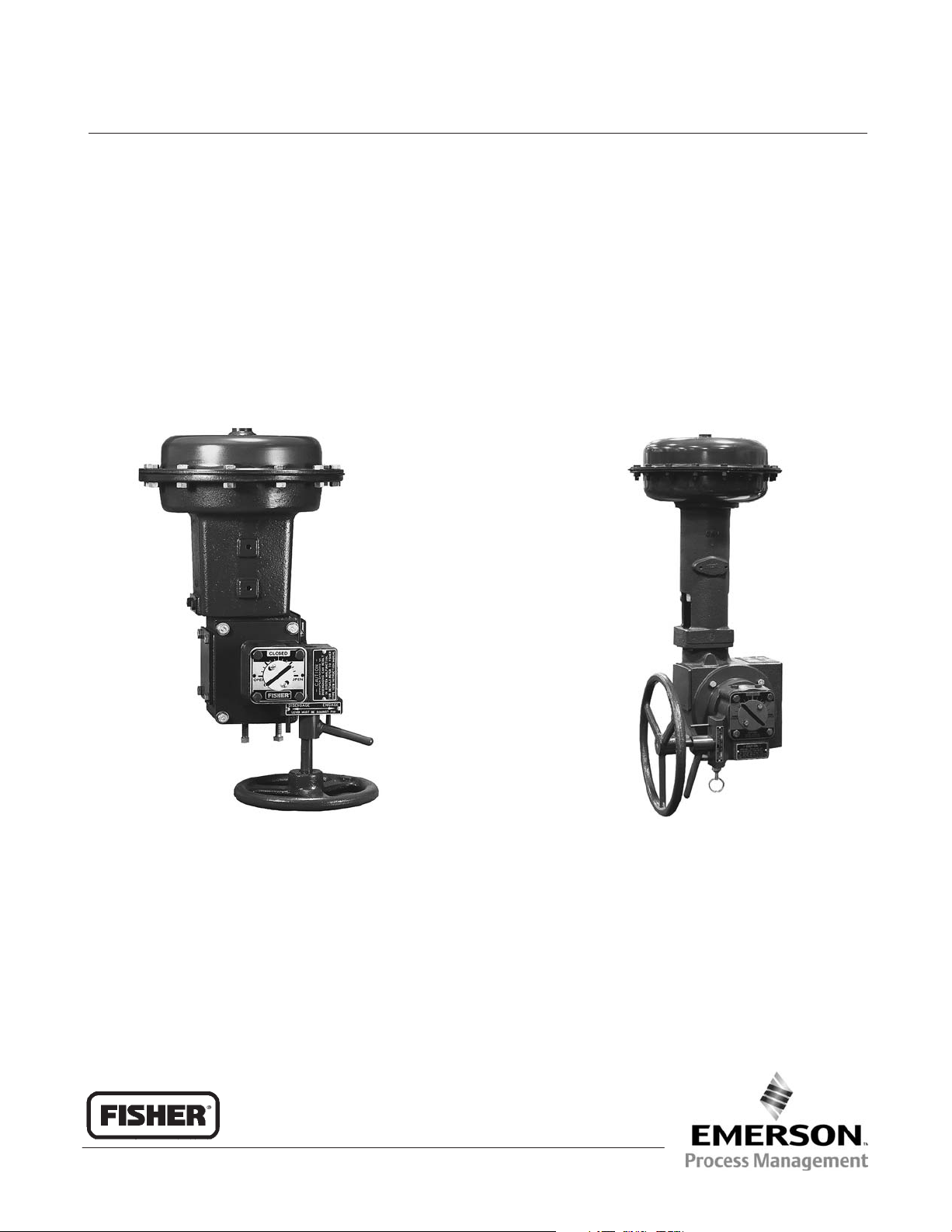
Fisherr 1078 manual actuators, figures 1 and 2, are
declutchable actuators for manual operation of
control valves and equipment that use power
actuators. The 1078 manual actuator mounts directly
to Fisher 1051 sizes 33, 40, and 60; 1052 sizes 33,
40, 60, and 70; 1061 sizes 30, 40, 60, 68, 80, and
100; and to all sizes of 1066 and 1066SR actuators.
For 1051 size 33, 1052 size 33, 1066, and 1066SR
actuators, coupling to the power actuator is via a
flatted shaft installed in the lever or hub. The
dimensions of these shafts are the same as those
used with H mounting adaptations. The stub shaft
fits into a square broach in the manual actuator
sector, and spacers secure the shaft in the
appropriate position.
W6244−1/IL
Figure 1. Fisherr 1078 Declutchable Manual Actuator
Mounted on a 1052 Size 33 Actuator
(Standard Construction)
www.Fisher.com
W6283/IL
Figure 2. Fisherr 1078 Declutchable Manual Actuator
Mounted on a 1052 Size 40 Actuator and V500 Valve
(Optional Construction)
D101339X012
Page 2

1078 Manual Actuator
Specifications
Product Bulletin
61.8:1078
January 2009
Available Configurations
Direct and reverse acting; see Handwheel
Rotation and the Ordering Information section,
(Standard construction is with the handwheel
shaft pointing down away from the power actuator
as shown in figure 1)
Manual Actuator Sizes
See tables 1, 2, 3 and 4
See figures 4 and 5 for dimensions
Coupling Shaft Diameters
See tables 1, 2, 3 and 4
Power Actuator Compatibility
See tables 1, 2, 3 and 4
Maximum Torque Output
See tables 1, 2, 3 and 4
Wheel-Rim Force
See tables 1, 2, 3 and 4
Handwheel Rotation
Clockwise handwheel rotation closes the valve.
Direct-acting units produce output rotation
matching input rotation; reverse-acting units
produce output rotation opposite input rotation.
Standard Mounting Positions
J1051 (size 33) or 1052 (size 33): Handwheel
down (see figure 1)
J1051 (size 40 and 60) (see figure 2) or 1052
(size 40, 60, and 70)
handwheel right-hand or left-hand mount
(optional)
J1061 (sizes 30, 40, 60, 68, 80, and 100)
Handwheel down (std) or handwheel right-hand or
left-hand mount (optional)
J1066 or 1066SR: Handwheel to left (see figure
3) or, with a 67AFR, handwheel down
Approximate Weight Without Handwheel
Size AAA: 2.7 kg (6 pounds)
Size AA: 6.8 kg (15 pounds)
Size A: 9.5 kg (21 pounds)
Size 2A: 13.6 kg (30 pounds)
Size 1A: 15.9 kg (35 pounds)
Size B: 23.1 kg (51 pounds)
Size C: 29.9 kg (66 pounds)
Size D: 63.5 kg (140 pounds)
Size
II-FA: 81.6 kg (180 pounds)
Handwheel Weight
(1)
: Handwheel down (std) or
(1)
:
Construction Materials
Housing and Cover: Cast iron
Drive Sleeve/Gear (Sector): Aluminum/bronze
Worm Gear: Heat-treated steel
Input Shaft and Eccentric: Low-carbon steel
Pin Detent: 300 Series stainless steel
Handwheel or Input Shaft Bearings: Bronze
1. If a positioner is used, the right-hand or left-hand mounting option will be limited to the side away from the positioner.
2
6-inch: 1.8 kg (4 pounds)
8-inch: 2.3 kg (5 pounds)
12-inch: 3.2 kg (7 pounds)
16-inch: 6.8 kg (15 pounds)
24-inch: 5.4 kg (12 pounds)
30-inch: 6.4 kg (14 pounds)
36-inch: 7.3 kg (16 pounds)
Page 3
Product Bulletin
61.8:1078
January 2009
1078 Manual Actuator
41B0314-A / DOC
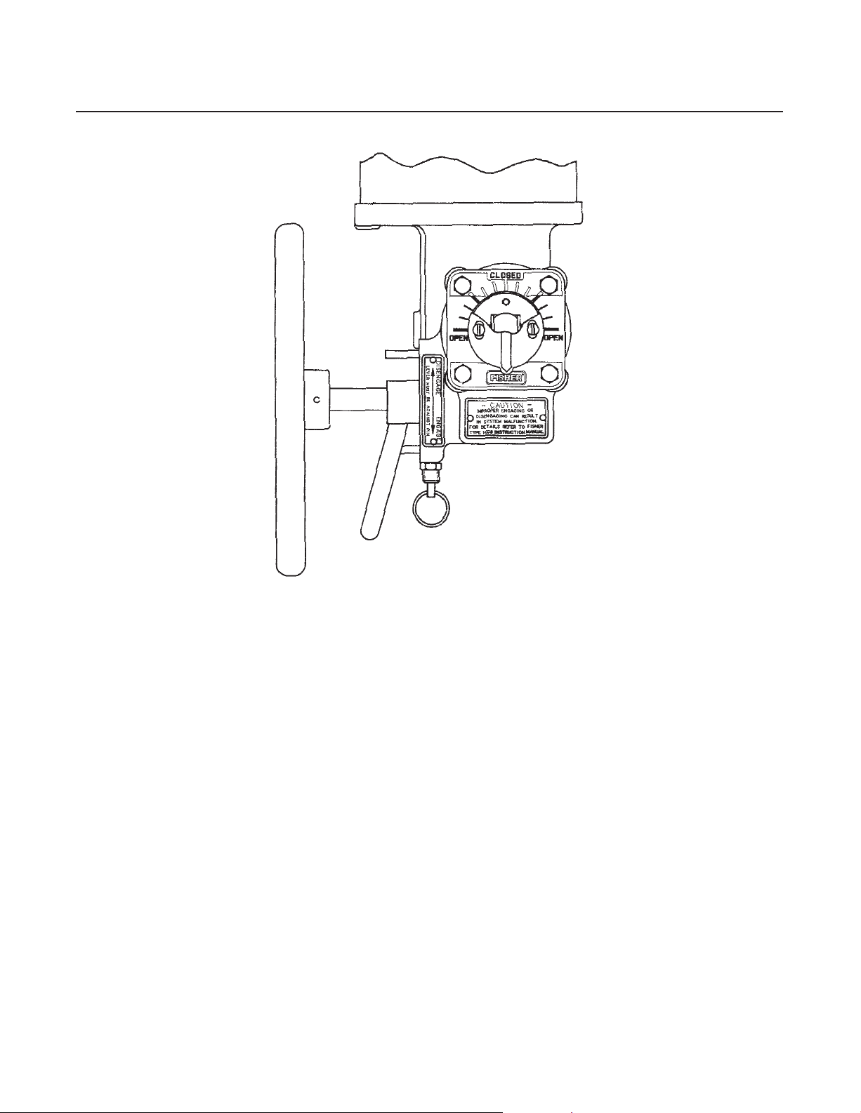
Figure 3. Fisherr 1078 Declutchable Manual Actuator Mounted on a 1066 Actuator
Features
DDirect Attachment to the Power
ActuatorDirect mounting to the actuator housing
simplifies installation and eliminates the need for yokes
and other brackets.
DEngage Manual Actuator At Any Point of
RotationA lever-operated eccentric bearing
support on the input shaft allows engagement of the
worm gear with the sector at any point of rotation.
Because the travel indicator components are
mounted on a through shaft, accurate travel
indication is maintained during manual actuator
disengagement or engagement.
DPositive OperationThe disengagement
lever is locked in both the engaged and disengaged
positions by a detent mechanism, which must be
released before the lever can be moved. This
provision reduces the possibility of inadvertent or
accidental operation. In addition, stop-pins at the
fully engaged and fully disengaged positions provide
positive limits for lever travel. (Note that stop pins
are not available on 1078 size
II-FA actuators.)
3
Page 4
Product Bulletin
1078 Manual Actuator
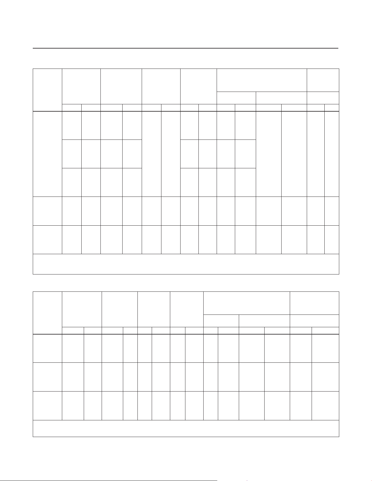
Table 1. Fisherr 1051, 1052, and 1066SR Actuator Size Selection and Specifications for Sizes AAA, AA, and A
MANUAL
ACTUATOR
SIZE
(max output
torque)
AAA
(2400 in.lbs)
AA
(4800 in.lbs)
A
(8200 in.lbs)
1. Requires flatted shaft as in the H mounting adaptation.
2. Field conversion of actuators for F and G mounting adaptations requires installation of new parts. The 1051 or 1052 Size 33 actuator requires installation of appropriate lever and stub
shaft. The 1066 actuator requires installation of appropriate hub assembly.
3. Compare table value with torque requirements of the valve plus the torque required to compress the power actuator spring (from Fisher Catalog 14). Note that dynamic torque of the
valve may have a positive or negative effect on total torque required.
SHAFT SIZE
mm Inch Type Size mm Inch
12.7
15.9
19.1
(22.2,
25.4)
12.7
15.9
19.1
(22.2,
25.4)
12.7
15.9
19.1
(22.2,
25.4)
12.7
15.9
19.1
(22.2,
25.4)
12.7
22.2,
25.4)
(31.8,
38.1)
(1)
1/2
5/8
3/4
(7/8,
1)
1/2
5/8
3/4
(7/8,
1)
1/2
5/8
3/4
(7/8,
1)
1/2
5/8
3/4
(7/8,
1)
3/4
(7/8,
1)
(1-1/4,
1-1/2)
POWER
ACTUATOR
1051 33
1052 33
1066SR 20
1066SR 27 305 12
1066SR 75 610 24
(2)
STANDARD
HANDWHEEL
DIAMETER
305 12
MAXIMUM
TORQUE
NSm LbfSin
143
223
271
271
190
270
271
271
169
249
271
271
283
363
464
541
717
926
926
(3)
1271
1981
2400
2400
1681
2391
2400
2400
1495
2205
2400
2400
2515
3225
4120
4800
6350
8200
8200
WHEEL-RIM-FORCE
For Maximum
Torque
N Pounds N Pounds 60 90
157
245
298
298
209
297
298
298
186
274
298
298
218
279
357
416
299
385
385
35
55
67
67
47
66
67
67
42
61
67
67
49
63
81
94
66
85
85
For Less Than
Maximum Torque
Divide
NSm req’d
by 0.91
Divide
NSm req’d
by 1.3
Divide
NSm req’d
by 2.4
req’d by
req’d by
req’d by
Divide
lbfSin
36
Divide
lbfSin
51
Divide
lbfSin
96
61.8:1078
January 2009
HAND-
WHEEL
TURNS FOR
ROTATION
Degrees
4 6
5.7 8.5
5.3 8
Table 2. Fisherr 1066 Actuator Size Selection and Specifications for Sizes AAA, AA, and A
STANDARD
MANUAL
ACTUATOR
SIZE
(max output
torque)
AAA
(2400 in.lbs)
AA
(4800 in.lbs)
A
(8200 in.lbs)
1. Requires flatted shaft as in the H mounting adaptation.
2. Field conversion of actuators for F and G mounting adaptations requires installation of new parts. The 1066 actuator requires installation of appropriate hub assembly.
3. Compare table value with torque requirements of the valve (from Fisher Catalog 14). Note that dynamic torque of the valve may have a positive or negative effect on total torque
required.
4
SHAFT SIZE
mm Inch Type Size mm Inch
12.7
15.9
19.1
(22.2,
25.4)
12.7
15.9
19.1
(22.2,
25.4)
12.7
(22.2,
25.4)
(31.8,
38.1)
(1)
1/2
5/8
3/4
(7/8,
1)
1/2
5/8
3/4
(7/8,
1)
3/4
(7/8,
1)
(1-1/4,
1-1/2)
POWER
ACTUATOR
1066 20 305 12
1066 27 305 12
1066 75 610 24
(2)
HAND-
WHEEL
DIAMETER
MAXIMUM
TORQUE
NSm LbfSin
58
138
239
271
58
138
239
467
239
467
926
(3)
515
1225
2120
2400
515
1225
2120
4140
2120
4140
8200
WHEEL-RIM-FORCE
For Maximum
Torque
N Pounds N Pounds 60 90
62
44
98
14
34
59
67
10
24
41
81
22
43
85
151
262
298
106
182
360
191
385
For Less Than
Maximum Torque
Divide
NSm req’d
by 0.91
Divide
NSm req’d
by 1.3
Divide
NSm req’d
by 2.4
req’d by
req’d by
req’d by
Divide
lbfSin
36
Divide
lbfSin
51
Divide
lbfSin
96
HANDWHEEL
TURNS FOR
ROTATION
Degrees
4 6
5.7 8.5
5.3 8
Page 5

Product Bulletin
61.8:1078
January 2009
Table 3. Fisherr 1051and 1052 Actuator Size Selection and Specifications for Sizes 2A, 1A, B, and C
STANDARD
MANUAL
ACTUATOR
SHAFT SIZE
POWER
ACTUATOR
SIZE
(max output
torque)
mm Inch Type Size mm Inch
12.7 1/2
2A
(4800 in.lbs)
15.9,
14.3x
9.5
19.1 3/4
(22.2,
25.4)
31.8 1-1/4 541 4800 416 94
5/8,
5/8
1051
1052
(4)
40
9/16x
(7/8,1) 467
12.7 1/2
1A
(8200 in.lbs)
15.9,
14.3x
9.5
19.1 3/4
(22.2,
25.4)
31.8 1-1/4
19.1 3/4
(22.2,
25.4)
31.8 1-1/4
31.8,
28.6x
31/8
38.1
31.8x
38.1
(44.4,
50.8),
39.7
x44.5
5/8,
9/16x
5/8
1051
1052
(3)
40 305 12
(7/8,1) 467
1051
1052
1051
(7/8,1)
10524060
1051
10524060
1-1/4,
1-1/8x
1-1/4
1-1/2,
1-1/4x
1-1/2
1051
10526070
(1-3/4,
2),
1-9/16
x1-3/4
3/4
B
31.8
(12,000
in.lbs)
38.1,
(44.4,
50.8)
C
31.8 1-1/4
(18,000
in.lbs)
(44.4,
50.8)
1. Field conversion of actuators for F and G mounting adaptations requires installation of new parts. The 1051 or 1052 Size 33 actuator requires installation of appropriate lever and stub
shaft.
2. Compare table value with torque requirements of the valve plus the torque required to compress the power actuator spring (from Fisher Catalog 14). Note that dynamic torque of the
valve may have a positive or negative effect on total torque required.
3. 2A 3/4 inch shaft will also mount on the 1051 and 1052 size 60.
4. Maximum torque of connection between power and manual actuator.
5. If mounted on the 1051 and 1052 Size 70, the Travel is for only 60 Degrees.
7/8-1
1-1/4
1-1/2,
(1-3/4,
2)
(1-3/4,
2)
1051
10526070
1051
10526070
HAND-
(1)
WHEEL
MAXIMUM
TORQUE
(2)
DIAMETER
NSm LbfSin
203 8 380 3365 441 99
460 4075 354 80
305 12
541 4800 416 94
(4)
4140
(4)
429 3795 330 74
509 4505 392 88
541 4800 416 94
(4)
4140
(4)
541 4800 416 94
610 24 929 8200 378 85
(5)
610 24 1356 12,000 369 83
1735 15,355 361 79
1839 16,275 383 84
610 24
2034 18,000 414 93
2034 18,000 414 93
For Maximum
N Pounds N Pounds 60 90
360 81
360 81
1078 Manual Actuator
WHEEL-RIM-FORCE
Torque
For Less Than
Maximum Torque
Divide
NSm req’d
by 0.86
req’d by
Divide
NSm req’d
by 1.3
req’d by
Divide
NSm req’d
by 1.3
req’d by
Divide
NSm req’d
by 2.4
req’d by
Divide
NSm req’d
by 3.6
req’d by
Divide
NSm req’d
by 4.8
req’d by
Divide
lbfSin
34
Divide
lbfSin
51
Divide
lbfSin
51
Divide
lbfSin
96
Divide
lbfSin
144
Divide
lbfSin
194
HANDWHEEL
TURNS FOR
5.7 8.5
5.3 8
6.7 10
9 13.5
ROTATION
Degrees
5
Page 6

Product Bulletin
1078 Manual Actuator
Table 4. Fisherr 1061 Actuator Size Selection and Specifications for Sizes 2A, 1A, B, C, D, and II-FA
STANDARD
MANUAL
ACTUATOR
SHAFT SIZE
POWER
ACTUATOR
SIZE
(max output
torque)
mm Inch Type Size mm Inch
12.7 1/2
15.9,
14.3x
9.5
2A
(4800 in.lbs)
1A
(8200 in.lbs)
B
(12,000
in.lbs)
C
(18,000
in.lbs)
D
(30,000
in.lbs)
(2)
II-FA
(60,000
in.lbs)
1. Compare table value with torque requirements of the valve (from Fisher Catalog 14). Note that dynamic torque of the valve may have a positive or negative effect on total torque
required.
2. Has spur gear.
3. 2A 3/4 inch shaft will also mount on the 1061 size 40, 60, and 68.
4. Maximum torque of connection between power and manual actuator.
19.1
(22.2,
25.4)
31.8 1-1/4 541 4800 416 94
19.1 3/4
(22.2,
25.4)
31.8,
28.6x
31/8
38.1
31.8x
38.1
(44.4,
50.8),
39.7
x44.5
19.1 3/4
22.2,
25.4
31.8 1-1/4
38.1,
(44.4,
50.8)
31.8 1-1/4
(44.4,
50.8)
(44.4,
50.8)
54,
63.5
57.2x
63.5
76x
63.5,
101.6x
63.5
76x
63.5,
101.6x
63.5
5/8,
9/16x
5/8
1061 30
(3)
3/4
(7/8,1)
1051,
1061
(7/8,1) 1061 467 4140 382 86
1-1/4,
1-1/8x
1-1/4
1-1/2,
1-1/4x
1-1/2
(1-3/4,
1-9/16
x1-3/4
7/8,1 468 4140 130 29
1-1/2,
(1-3/4,
(1-3/4,
(1-3/4,
2-1/8,
2-1/2,
2-1/4x
2-1/2
1/2,4x
2 1/2
1/2,4x
2 1/2
1061
2),
1061
1061
2)
1061
2)
2)
1061
3x2
1061
3x2
1061
40,
60,
68
40,
60,
68
40,
60,
68
40,
60,
68
80,
100
80,
100
HAND-
WHEEL
MAXIMUM
TORQUE
(1)
WHEEL-RIM-FORCE
DIAMETER
For Maximum
Torque
NSm LbfSin
58 515 89 20
152 6
203 8 239 2120 276 62
305 12
305 12
610 24 929 8200 378 85
610 24
610 24
762 30 2658 23,524 369 82
914 36 3390 30,000 394 87
406 16 6301 55,762 400 90
138 1225 214 48
(4)
467
4140
239 2120 276 62
239 2120 66 15
1109 9815 308 68
1356 12,000 377 83
1109 9815 231 51
2034 18,000 424 93
N Pounds N Pounds 60 90
(4)
360 81
For Less Than
Maximum Torque
Divide
NSm req’d
by 0.66
Divide
NSm req’d
by 0.86
Divide
NSm req’d
by 1.3
Divide
NSm req’d
by 1.2
Divide
NSm req’d
by 2.4
Divide
NSm req’d
by 3.6
Divide
NSm req’d
by 4.8
Divide
NSm req’d
by 7.2
Divide
NSm req’d
by 8.6
Divide
NSm req’d
by 15.7
Divide
lbfSin req’d
Divide
lbfSin req’d
Divide
lbfSin req’d
Divide
lbfSin req’d
Divide
lbfSin req’d
Divide
lbfSin req’d
by 144
Divide
lbfSin req’d
by 194
Divide
lbfSin req’d
by 287
Divide
lbfSin req’d
by 345
Divide
lbfSin req’d
by 619
by 26
by 34
by 51
by 48
by 96
61.8:1078
January 2009
HANDWHEEL
TURNS FOR
ROTATION
Degrees
5.7 8.5
5.3 8
5.3 8
6.7 10
9 13.5
10.7 16
48 72
6
Page 7

Product Bulletin
61.8:1078
January 2009
Table 5. Dimensions for Actuator Sizes AAA, AA, and A
1078
Size
AAA 20, 33 305 184 40 67 178 204 106 46 51 57.1 SQ − − −
AA 27 305 203 56 70 181 216 94 59 64 76.2 SQ − − −
A 75 610 381 68 83 337 378 238 67 73 88.9 SQ − − −
AAA 20, 33 12.00 7.25 1.56 2.62 7.00 8.02 4.18 1.82 2.02 2.25 SQ − − −
AA 27 12.00 8.00 2.19 2.75 7.12 8.50 3.69 2.31 2.50 3.00 SQ − − −
A 75 24.00 15.00 2.69 3.25 13.25 14.88 9.38 2.63 2.88 3.50 SQ − − −
ROTARY
ACTUATOR
SIZE
A B C D E F G H J
mm
Inches
1078 Manual Actuator
Square
Bolt
Pattern
Circular
Bolt
Pattern
11B2634-C
A5431-1 / IL
Figure 4. Dimensions for Actuator Sizes AAA, AA, and A (also see table 5)
7
Page 8

Product Bulletin
1078 Manual Actuator
Table 6. Dimensions for Actuator Sizes 2A, 1A, B, C, D, and II-FA
1078
Size
2A
1A
B
C 610 254 102 149 400 416 200 105 111
D
II-FA 406 356 11 7 203 337 328 84 119 125
2A
1A
B
C 24.00 10.00 4.00 5.88 15.75 16.38 7.88 4.12 4.38
D
II-FA 16.00 14.00 4.62 8.00 13.25 12.94 3.31 4.69 4.94
A B C D E F G H J
mm
152 230 55.4 116 155 140 17.5 58.7 63.5
203 181 165 42.9
305 232 216 93.7
305 229 68.3 124 235 229 82.6 69.9 76.2
610 387 381 235
203 229 84.1 140 194 191 19.1 82.6 88.9
305 244 241 69.9
610 397 394 222
762 254 11 7 203 505 506 262 11 9 125
914 581 583 338
Inches
6.00 8.00 2.18 4.56 6.12 5.5 0.69 2.31 2.50
8.00 7.12 6.5 1.69
12.00 9.12 8.5 3.69
12.00 9.00 2.69 4.88 9.25 9.00 3.25 2.75 3.00
24.00 15.25 15.00 9.25
8.00 9.00 3.31 5.50 7.62 7.50 0.75 3.25 3.50
12.00 9.62 9.50 2.75
24.00 15.62 15.50 8.75
30.00 10.00 4.62 8.00 20.25 19.94 10.31 4.69 4.94
36.00 23.25 22.94 13.31
January 2009
61.8:1078
8
Page 9

Product Bulletin
61.8:1078
January 2009
1078 Manual Actuator
ENGAGED
G
ENGAGED
E
D
G
DISENGAGED
ENGAGED
CB
H ENGAGED
J DISENGAGED
SIZES 2A, 1A, B, C, D
E
D
DISENGAGED
B
C
B2463 / IL
135_
H ENGAGED
J DISENGAGED
SIZE II-FA
ENGAGED
Figure 5. Dimensions for Actuator Sizes 2A, 1A, B, C, D, and II-FA (also see table 6)
9
Page 10

1078 Manual Actuator
Product Bulletin
61.8:1078
January 2009
Ordering Information
Whenever a power actuator is ordered with a 1078
manual actuator, all components are configured and
mounted according to specifications of the order.
Size AAA, AA, and A
Field installation of the 1078 onto existing actuators
with F or G mounting adaptations requires
installation of new power actuator parts. (The F and
G mounting adaptations are the mounting methods
normally used to mount 1051, 1052, 1066 and
1066SR actuators on Fisher valves.) For the 1051 or
1052 size 33, a lever with stub shaft must be
installed. For the 1066 or 1066SR actuator, a hub
assembly with stub shaft must be installed. Field
installation on power actuators with H mounting
adaptations requires dual stub shaft construction
(standard on the 1066 or 1066SR actuator). (The H
mounting adaptation is the mounting method
normally used to mount 1051, 1052, 1066 and
1066SR actuators on equipment and valves other
than Fisher valves.) Installation of a valve to bypass
cylinder or diaphragm pressure during manual
operation is also recommended.
Table 7. Handwheel/Valve Shaft Rotation
1078 ACTUATOR ACTION
VALV E
Right-Hand Left-Hand
8510, 8522,
8532, 8560,
and 9500
V150, V200,
and V300
V250
V500 and
CV500
1. Direct acting is when the clockwise handwheel rotation produces clockwise
valve shaft rotation to close the valve.
2. Reverse acting is when the clockwise handwheel rotation produces counter
clockwise valve shaft rotation to close the valve.
3. A left hand ball will be required for the NPS 3 through 12 series B and the NPS
14 through 20, with or without an attenuator.
Direct Acting
Reverse
Acting
Reverse
Acting
Reverse
Acting
Actuator Mounting
(1)
Direct Acting NA
(2)
Reverse
Direct Acting NA
Reverse
Acting
Acting
Left-Hand
(Optional)
Direct Acting
NA
(3)
When ordering, specify:
1. Power actuator type and size, and valve shaft
size.
2. Right or left hand mounting and desired mounting
position.
3. Direct or reverse acting manual actuator
construction. Refer to the mounting positions shown
in the appropriate actuator bulletin and order
according to the guidelines in table 7.
Size 2A, 1A, B, C, D, and
II-FA
Field installation of the 1078 onto the following
existing actuators with F or G mounting adaptations
[1051 (sizes 40 and 60), 1052 (sizes 40, 60, and 70),
and 1061 (sizes 30, 40, 60, 68, 80, and 100)]
requires additional parts in most cases. Remove the
cover and hub and then replace with the 1078
actuator. Most assemblies require a new lever and
splined adaptor.
Note
Neither Emerson, Emerson Process
Management, nor any of their affiliated
entities assumes responsibility for the
selection, use, or maintenance of any
product. Responsibility for the
selection, use, and maintenance of any
product remains with the purchaser
and end-user.
10
Page 11

Product Bulletin
61.8:1078
January 2009
1078 Manual Actuator
11
Page 12

1078 Manual Actuator
Product Bulletin
61.8:1078
January 2009
Fisher is a mark owned by one of the companies in the Emerson Process Management business division of Emerson Electric Co. Emerson
Process Management, Emerson, and the Emerson logo are trademarks and service marks of Emerson Electric Co. All other marks are the property
of their respective owners.
The contents of this publication are presented for informational purposes only, and while every effort has been made to ensure their accuracy, they
are not to be construed as warranties or guarantees, express or implied, regarding the products or services described herein or their use or
applicability. All sales are governed by our terms and conditions, which are available upon request. We reserve the right to modify or improve the
designs or specifications of such products at any time without notice. Neither Emerson, Emerson Process Management, nor any of their affiliated
entities assumes responsibility for the selection, use or maintenance of any product. Responsibility for proper selection, use, and maintenance of
any product remains solely with the purchaser and end-user.
Emerson Process Management
Marshalltown, Iowa 50158 USA
Sorocaba, 18087 Brazil
Chatham, Kent ME4 4QZ UK
Dubai, United Arab Emirates
Singapore 128461 Singapore
www.Fisher.com
12
EFisher Controls International LLC 1989, 2009; All Rights Reserved
 Loading...