

Page 1
1077 Handwheel Actuator
D101625X012
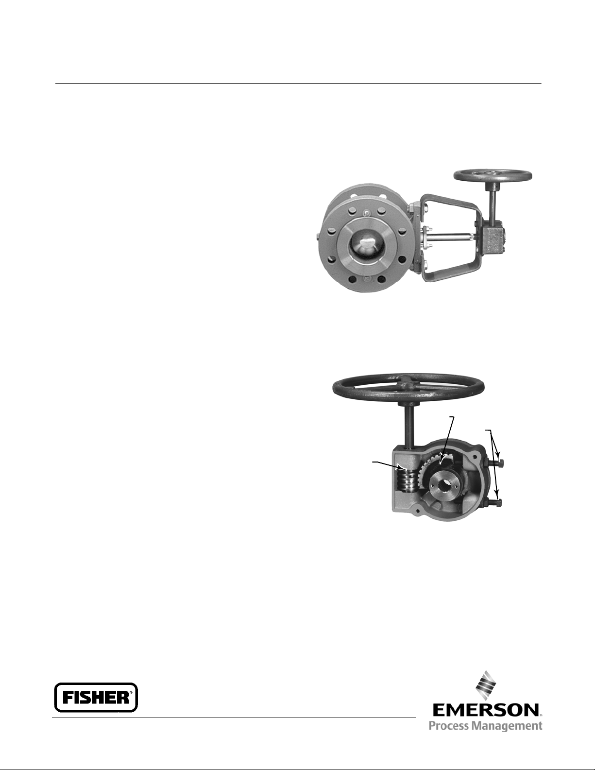
Fisherr 1077 Manual Handwheel
Rotary Actuator
Fisher 1077 manual-only handwheel actuator is for use
with rotary-shaft valves such as the 9500 butterfly
valve; 8532, 8560, and 8580 eccentric disc valves;
V150, V200 and V300 Vee-Ballt valves; V250 valves;
and CV500 and V500 valves. Figure 1 shows the
gearbox of the actuator. In this actuator, torque is
transmitted from the handwheel through the
handwheel input shaft to a worm and drive sleeve gear
(sector) with splined bore. The worm and drive sleeve
gear multiply the torque and transmit it to a splined
valve shaft or splined stub shaft. The size 10-KE:6
actuator additionally has a spur gear reduction drive
for increased torque capability.
W8176-1
Fisher 1077 Handwheel Actuator
Product Bulletin
61.8:1077
July 2012
Features
Easy to Install and Maintain–Splined valve shaft
mates directly with the drive gear sleeve, reducing
the number of parts required and simplifying
installation and maintenance.
Easy to Operate–Handwheel rotation direction
required to open the valve disc or ball is marked on
the handwheel; the rotation indicator is marked in
bold print at the open and closed positions and with
bold incremental lines to indicate the valve disc or
ball position.
Consistency of Operation–When installed
according to instructions, clockwise handwheel
rotation closes the valve in all applications.
Accurate Valve Disc or Ball P ositioning–Travel stops
can be adjusted and locked in place to provide
accurate disc or ball positioning at closed
(0-degree) and open (90-degree) positions. Travel
stops for 60-degree operation may be used to
establish a disc or ball closing stop at any angle
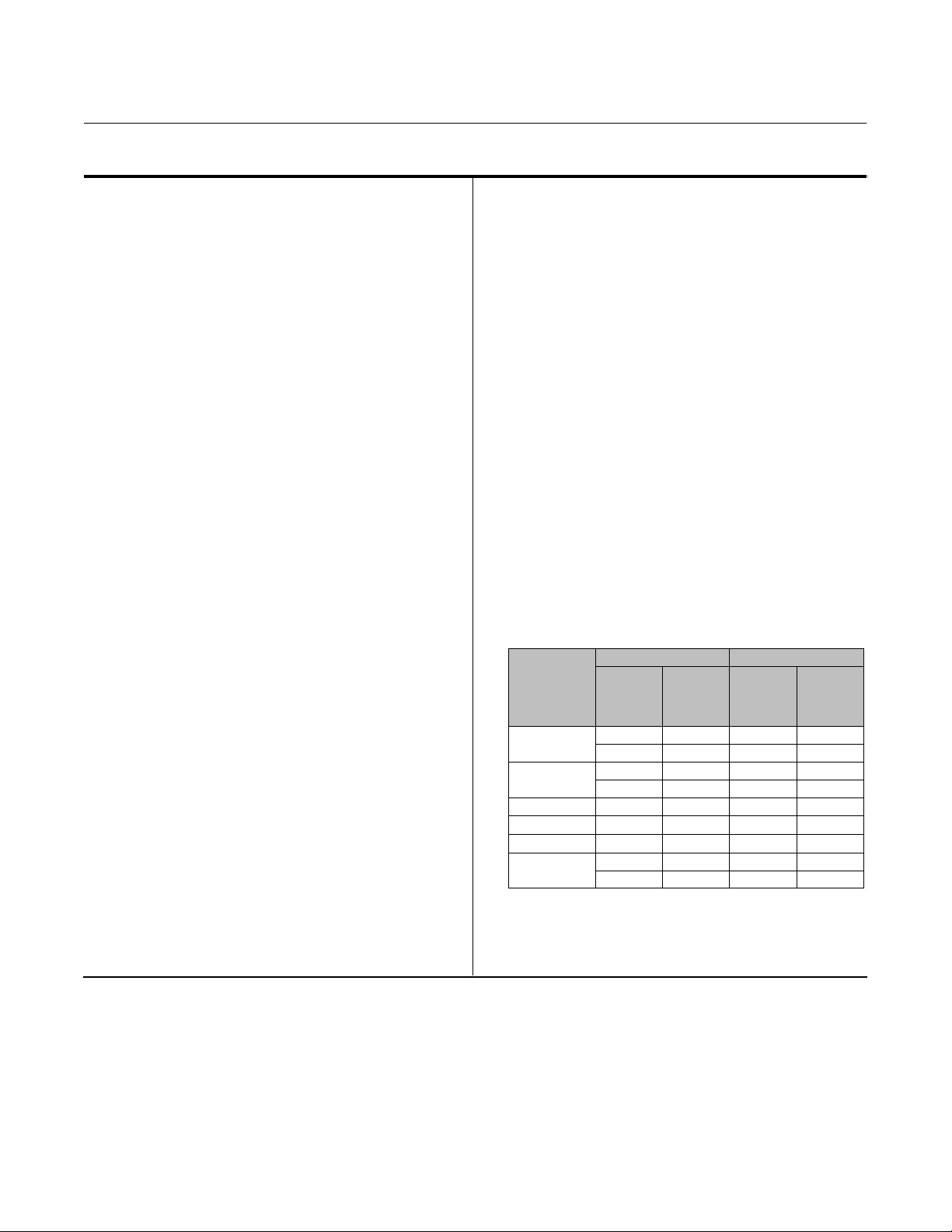
Figure 1. Gearbox Subassembly
DRIVESLEEVEGEARAND
HUB
WORM
W4580
between 0 and 30 degrees and/or to establish a disc or
ball opening stop at any angle between 60 and 90
degrees. This option is available on sizes 2-KE and 7-KE
as a set screw change. For sizes 0-KE, 6-KE, 9-KE, and
10-KE:6, a different actuator is required when
changing from 90-degree to 60-degree ball rotation.
TRAVEL
STOPS
www.Fisher.com
Page 2
Product Bulletin
61.8:1077
July 2012
Specifications
1077 Handwheel Actuator
D101625X012
Available Configuration
Manual-only handwheel actuator for use with splined
and keyed rotary-shaft valves
Actuator Sizes
See tables 1 and 2
Acceptable Valve Shaft Diameters
See tables 1 and 2
Output Torque
See tables 1 and 2
Wheel-Rim Force
See tables 1 and 2
Handwheel Turns Required for Full Rotation
See tables 1 and 2
Handwheel Rotation
Direct Acting Construction: Clockwise handwheel
rotation closes the valve (produces clockwise rotation
of the valve shaft) as shown in figure 2.
Reverse Acting Construction: Clockwise handwheel
rotation closes the valve (produces counterclockwise
rotation of the valve shaft) as shown in figure 2.
Maximum Output Rotation
Standard: 90 degrees
Optional: 60 degrees
J valve ball or disc closed
position may be set to any angle between 0 and 30
degrees, and/or
J valve ball or disc open position
may be set to any angle between 60 and 90 degrees.
(This option is available on actuator sizes 2-KE and
7-KE as a set screw change. For sizes 0-KE, 6-KE, 9-KE,
and 10-KE:6, a different actuator is required when
changing from 90-degree to 60-degree ball rotation.)
Construction Materials
Housing: Cast iron
Housing Cover: Cast iron
Worm: Steel
Drive Sleeve Gear:
For Sizes 0-KE through 7-KE: Phosphor bronze sector
with steel hub
For Sizes 9-KE and 10-KE:6: Manganese bronze sector
with ductile iron hub
Worm Gear Shaft and Handwheel Shaft: Steel
Handwheel:
Through 431 mm (16-Inch) Diameter:Castiron
Over 431 mm (16-Inch) Diameter: Fabricated steel
Mounting Yoke
For N PS 30 and 36 8510, NPS 16 V250, and any other
valve with 76.2 or 88.9 mm (3 or 3-1/2 Inch) Shaft
Diameter:Castiron
For All Valve Bodies Other Than Those Listed Above:
Painted steel
Mounting Positions
J Right-hand (actuator on the right side of the valve
when viewed from the valve inlet) or
J Left-hand
(actuator on the left side of the valve when viewed
from the valve inlet). Position 1 as shown in figure 3 is
standard; however, the actuator may be m ounted in
any of the positions shown in figure 3. Refer to figure 2
to determine the correct actuator construction.
Approximate Weight
METRIC UNITS U.S. UNITS
ACTUATOR
0-KE
2-KE
6-KE 610 20.2 24 43
7-KE 762 28.2 30 60
9-KE 914 40.9 36 87
10-KE:6
Handwheel
Diameter,
mm
152 3.7 6 8
203 4.7 8 10
203 10.3 8 22
305 11.3 12 24
432 62.6 16 133
610 62.6 24 133
Weight of
Actuator
Assembly,
kg
Handwheel
Diameter,
Inches
Weight of
Actuator
Assembly,
Pounds
Accessories
Position and Limit Switches:
or
J One or two limit switches, can be mounted
J One position switch,
2
Page 3

Product Bulletin
1077 Handwheel Actuator
D101625X012
Table1.ActuatorSizeSelection (Metric Units)
WHEEL-RIM FORCE
ACTUATOR
SIZE
ACCEPTABLE
VALVE SHAFT
DIAMETER
MAXIMUM
ALLOWABLE
TORQUE
(1)
HANDWHEEL
DIAMETER
To Produce
Maximum
Allowable
Torque
To Produce Torque
Lower Than Maximum
Allowable Shaft Torque
mm NSm mm N N
12.7
0-KE
15.9
19.1
22.2 and 25.4
22.2 and 25.4 468 203 485
2-KE
31.8
38.1
31.8
6-KE
38.1
44.5
50.8
7-KE
44.5
50.8
44.5
9-KE
50.8
63.5 3390
63.5 6305 431 431
10-KE:6
76.2 6780
88.9 6780
1. Values shown are the maximum allowable torque of a splined valve shaft except where indicated. Without regard to the shaft, maximum allowable torque output is 271 NSmforthesize
0-KE actuator, 678 N
10-KE:6 actuator.
2. Limited to this value by the maximum allowable output torque of the actuator.
3. Wheel-rim force required to produce maximum actuator output torque.
4. Handwheel is 152 mm (6-inch) diameter for keyed-shaft constructions.
Smforthesize2-KEactuator,1360NSmforthesize6-KEactuator,2260NSmforthesize7-KEactuator,3390N•mforthesize9-KEactuator,and6780NSmforthesize
58
138
240
271
678
678
1110
1360
1360
1360
2260
2260
2260
2260
152
152
(4)
(2)
203
203
129
307
396
445
Torque Req'd
(NSm) ÷ 0.4572
(3)
Torque Req'd
(NSm) ÷ 0.6096
Torque Req'd
(NSm) ÷ 0.9652
(2)
(2)
305
305
610
(2)
(2)
(2)
(2)
610
610
610
762
762
762
762
(2)
914 463
467
467
365
445
445
445
440
440
436
436
(3)
(3)
(2)
(2)
(3)
(3)
Torque Req'd
(NSm) ÷ 1.4478
Torque Req'd
(NSm) ÷ 3.0480
Torque Req'd
(NSm) ÷ 5.1435
Torque Req'd
(NSm) ÷ 6.096
(3)
Torque Req'd
(NSm) ÷ 7.3152
Torque Req'd
(NSm) ÷ 15.476
(2)
(2)
610 310
610 310
(3)
(3)
Torque Req'd
(NSm) ÷ 21.848
Torque Req'd
(NSm) ÷ 21.848
HANDWHEEL TURNS
REQUIRED FOR FULL VALVE
DISC OR BALL ROTATION
60-Degree
Rotation
4 6
4 6
6-1/2 9-1/2
6-1/2 9-1/2
6-1/2 10
9 13-1/2
10-1/2 16
10-1/2 16
48 72
48 72
48 72
61.8:1077
July 2012
90-Degree
Rotation
3
Page 4

Product Bulletin
61.8:1077
July 2012
Table2.ActuatorSizeSelection(U.SUnits)
WHEEL-RIM FORCE
ACCEPTABLE
ACTUATOR
SIZE
VALVE SHAFT
DIAMETER
Inches Inch-Pounds Inches Pounds Pounds
1/2
0-KE
5/8
3/4
7/8 and 1
7/8 and 1 4140 8 109
2-KE
1-1/4
1-1/2
1-1/4
6-KE
1-1/2
1-3/4
2
7-KE
1-3/4
2
1-3/4
9-KE
2
2-1/2 30,000
2-1/2 55,762 16 97
10-KE:6
3 60,000
3-1/2 60,000
1. Values shown are the maximum allowable torque of a splined valve shaft except where indicated. Without regard to the shaft, maximum allowable torque output is 2400 inch-pounds for the
size 0-KE actuator, 6000 inch-pounds for the size 2-KE actuator, 12,000 inch-pounds for the size 6-KE actuator, 20,000 inch-pounds for the size 7-KE actuator, 30,000 inch-pounds for the size
9-KE actuator, and 60,000 inch-pounds for the size 10-KE:6 actuator.
2. Limited to this value by the maximum allowable output torque of the actuator.
3. Wheel-rim force required to produce maximum actuator output torque.
4. Handwheel is 152 mm (6-inch) diameter for keyed-shaft constructions.
MAXIMUM
ALLOWABLE
TORQUE
(1)
515
1225
2120
(2)
2400
(2)
6000
(2)
6000
9820
12,000
(2)
12,000
(2)
12,000
(2)
20,000
(2)
20,000
23,524
23,524
(2)
(2)
(2)
HANDWHEEL
DIAMETER
6
6
(4)
8
8
12
12
24
24
24
24
30
30
30
30
36 104
24 69
24 69
To Produce
Maximum
Allowable
Torque
29
69
89
(3)
100
(3)
105
(3)
105
82
100
(3)
100
(3)
100
(3)
99
(3)
99
98
98
(3)
(3)
(3)
To Produce Torque
Lower Than Maximum
Allowable Shaft Torque
(In.-Lb.) ÷ 18.00
(In.-Lb.) ÷ 24.00
(In.-Lb.) ÷ 38.00
(In.-Lb.) ÷ 57.00
(In.-Lb.) ÷ 120.00
(In.-Lb.) ÷ 202.50
(In.-Lb.) ÷ 240.00
(In.-Lb.) ÷ 288.00
(In.-Lb.) ÷ 612.00
(In.-Lb.) ÷ 864
(In.-Lb.) ÷ 864
1077 Handwheel Actuator
D101625X012
HANDWHEEL TURNS
REQUIRED FOR FULL VALVE
DISC OR BALL ROTATION
60-Degree
Rotation
Torque Req'd
Torque Req'd
Torque Req'd
Torque Req'd
Torque Req'd
Torque Req'd
Torque Req'd
Torque Req'd
Torque Req'd
Torque Req'd
Torque Req'd
4 6
4 6
6-1/2 9-1/2
6-1/2 9-1/2
6-1/2 10
9 13-1/2
10-1/2 16
10-1/2 16
48 72
48 72
48 72
90-Degree
Rotation
4
Page 5

1077 Handwheel Actuator
D101625X012
Table 3. Direct and Reverse Acting Actuator Constructions
VALVE SERIES OR DESIGN VALVE SERIES OR DESIGN
MOUNTING
Right-Hand
Left-Hand
Left-Hand
(Optional)
1. A left hand ball will be required for the NPS 3 through 12 Series B and the NPS 14 to 20, with or without attenuator.
(1)
Figure 2. Direct and Reverse Acting Actuator Constructions (also see table 3)
Ball/Plug
Rotation To
Close
CCW
CCW
CCW
CCW
CW
CW
V250 V150, V200 and V300
REVERSE REVERSE REVERSE
NA
NA
NA
NA
REVERSE REVERSE
DIRECT
CV500
V500
NA
NA
Disc/Ball
Rotation To
Close
CW
CW
CW
CW
NA
NA
Product Bulletin
61.8:1077
July 2012
V250
NA
NA
DIRECT DIRECT
NA
NA
8532, 8560
8580, and 9500
DIRECT
NA
NA
40B1561-A
DIRECT ACTING CONSTRUCTION
Installation
The valve body and actuator assembly may be installed
in any of the positions shown in figure 3. The actuator
will be factory mounted on the valve body in the
position specified.
REVERSE ACTING CONSTRUCTION
Dimensions are shown in figure 4. Make clearance
considerations before mounting the actuator to
determine the most suitable mounting position.
5
Page 6

Product Bulletin
61.8:1077
July 2012
Figure 3. Available Mounting Positions
POSITION 1
FLOW
DIRECTION FOR
RIGHT-HAND
MOUNTING
POSITION 4
DIRECT ACTING ACTUATOR CONSTRUCTION
POSITION 1
1077 Handwheel Actuator
D101625X012
VALVE BODY
FLOW DIRECTION
FOR
LEFT-HAND
MOUNTING
POSITION 3
FLOW
DIRECTION FOR
RIGHT-HAND
MOUNTING
30B0668-A
B2002-3
VALVE BODY
FLOW DIRECTION
FOR LEFT-HAND
MOUNTING
POSITION 4
POSITION 3
REVERSE ACTING ACTUATOR CONSTRUCTION
6
Page 7

Product Bulletin
1077 Handwheel Actuator
D101625X012
Table4.EnvelopeDimensions
ACTUATOR SIZE HANDWHEEL DIAMETER J VALVE SHAFT DIAMETER F H L M N V Z
mm
0-KE
2-KE
6-KE 610
7-KE 762 44.5, 50.8 152 381 105 103 191 324 384
9-KE
10-KE:6
0-KE0
2-KE
6-KE 24.00
7-KE 30.00 1-3/4, 2 6.00 15.00 4.12 4.06 7.50 12.75 15.12
9-KE
10-KE:6
1. Used with NPS 30, 36 8510 and NPS 16 V250.
2. The 19.1 mm (3/4-inch) keyed shaft construction uses a 152 mm (6-inch) handwheel.
152 12.7, 15.9
203 19.1
203 22.2, 25.4
305 31.8, 38.1 238 165 200 243
762 44.5, 50.8
914
406
610 76.2, 88.9
6.00 1/2, 5/8
8.00 3/4
8.00 7/8, 1
12.00 1-1/4, 1-1/2 9.38 6.50 7.88 9.56
30.00 1-3/4, 2
36.00
16.00
24.00 3, 3-1/2
(2)
, 22.2, 25.4 170
31.8, 38.1
44.5, 50.8 191 321 368
63.5 241
(1)
63.5
63.5
(1)
63.5
Inches
(2)
,7/8,1 6.69
1-1/4, 1-1/2
1-3/4, 2 7.50 12.62 14.50
2-1/2 9.50
(1)
2-1/2
2-1/2
(1)
2-1/2
164
70
124
145 356 83 84
178 406 119 117
178 419 127 117
2.75
4.88
5.69 14.00 3.25 3.31
7.00 16.00 4.69 4.62
7.00 16.50 5.00 4.62
45 52 111 186 222
221
79 79
6.44
1.75 2.06 4.38 7.31 8.75
8.69
3.12 3.12
61.8:1077
July 2012
111 187 230
165 213 260
191
346
305 448
241 346 432
305 448 533
4.38 7.38 9.06
6.50 8.38 10.25
7.50
12.00 17.62
9.50 13.62 17.00
12.00 17.62 21.00
13.62
17.00
21.00
432
533
Figure 4. Envelope Dimensions (also see table 4)
JØ
H
M
10B0529-H
E0870
L
F
V
N
SØ
Z
7
Page 8

Product Bulletin
61.8:1077
July 2012
Ordering Information
When ordering, specify:
Application
1077 Handwheel Actuator
D101625X012
tables and figures. Indicate a choice whenever there is
a selection to be made.
1. Valve body type or design, size, and shaft diameter.
2. Valve disc or ball rotation (e.g., 0 to 60 or 0 to 90
degrees). For adjustability between 0 and 30 degrees
for the closed stop position, or for adjustability
between 60 and 90 degrees for the open stop position,
the 60-degree travel stop is used. This option is
available on actuator sizes 2-KE, 7-KE, 9-KE, and
10-KE:6 as a set screw change. For sizes 0-KE and 6-KE
a different actuator is required when changing from
90-degree to 60-degree ball rotation.
3. Right- or left-hand mounting and desired mounting
position from figure 3. If the control valve assembly is
to be used for bidirectional flow, assume that the flow
direction arrows in figure 3 point to the seal retainer or
flow ring end of the valve body.
Handwheel Actuator
Refer to the Specifications section. Review the
description for each specification and in the referenced
Note
When specifying a mounting position, make certain that the
handwheel diameter specified will not interfere with the
valve body, pipe flanges, or line bolting connected to the
system.
Accessories
If ordering limit switches, specify the number of
switches desired (one or two). For one limit switch,
specify whether switching is to occur at the open or
closed valve position.
Valve Body and Accessories
Refer to the separate valve body and accessory
information bulletins for ordering information.
Neither Emerson, Emerson Process Management, nor any of their affiliated entities assumes responsibility for the selection, use or maintenance
of any product. Responsibility for proper selection, use, and maintenance of any product remains solely with the purchaser and end user.
Fisher and Vee-Ball are marks owned by one of the companies in the Emerson Process Management business unit of Emerson Electric Co. Emerson Process
Management, Emerson, and the Emerson logo are trademarks and service marks of Emerson Electric Co. All other marks are the property of their respective
owners.
The contents of this publication are presented for informational purposes only, and while every effort has been made to ensure their accuracy, they arenot
to be construed as warranties or guarantees, express or implied, regarding the products or services described herein or their use or applicability. All sales are
governed by our terms and conditions, which are available upon request. We reserve the right to modify or improve the designs or specifications of such
products at any time without notice.
Emerson Process Management
Marshalltown, Iowa 50158 USA
Sorocaba, 18087 Brazil
Chatham, Kent ME4 4QZ UK
Dubai, United Arab Emirates
Singapore 128461 Singapore
www.Fisher.com
E 1986, 2012 Fisher Controls International LLC. All rights reserved.
8
 Loading...