


Instruction Manual
D102010X012
EU and EW Series Valves
February 2020
Fisher
™
EU and EW Valves NPS 12 through 24 x 20
(Obsolete)
Contents
Introduction 1.................................
Safety Instructions 1............................
Specifications 2................................
Inspection and Maintenance Schedules 2...........
Parts Ordering 2................................
Installation 3..................................
Maintenance 4.................................
Latest Published Instruction Manual 5..............
Introduction
The product covered in this document is no longer in production. This document, which includes the latest published
version of the instruction manual, is made available to provide updates of newer safety procedures. Be sure to follow
the safety procedures in this supplement as well as the specific instructions in the included instruction manual.
Part numbers in the included instruction manual should not be relied on to order replacement parts. For replacement
parts, contact your Emerson sales office
.
For more than 30 years, Fisher products have been manufactured with asbestos‐free components. The included
manual might mention asbestos containing parts. Since 1988, any gasket or packing which may have contained some
asbestos, has been replaced by a suitable non‐asbestos material. Replacement parts in other materials are available
from your sales office.
Safety Instructions
Please read these safety warnings, cautions, and instructions carefully before using the product.
These instructions cannot cover every installation and situation. Do not install, operate, or maintain this product
without being fully trained and qualified in valve, actuator and accessory installation, operation and maintenance. To
avoid personal injury or property damage it is important to carefully read, understand, and follow all of the contents of
this manual, including all safety cautions and warnings. If you have any questions about these instructions, contact
your Emerson sales office before proceeding.
www.Fisher.com

EU and EW Series Valves
February 2020
Instruction Manual
D102010X012
Specifications
This product was intended for a specific range of service conditions‐‐pressure, pressure drop, process and ambient
temperature, temperature variations, process fluid, and possibly other specifications. Do not expose the product to
service conditions or variables other than those for which the product was intended. If you are not sure what these
conditions or variables are, contact your Emerson sales office
other pertinent information that you have available.
for assistance. Provide the product serial number and all
Inspection and Maintenance Schedules
All products must be inspected periodically and maintained as needed. The schedule for inspection can only be
determined based on the severity of your service conditions. Your installation might also be subject to inspection
schedules set by applicable governmental codes and regulations, industry standards, company standards, or plant
standards.
In order to avoid increasing dust explosion risk, periodically clean dust deposits from all equipment.
When equipment is installed in a hazardous area location (potentially explosive atmosphere), prevent sparks by proper
tool selection and avoiding other types of impact energy.
Parts Ordering
Whenever ordering parts for older products, always specify the serial number of the product and provide all other
pertinent information that you can, such as product size, part material, age of the product, and general service
conditions. If you have modified the product since it was originally purchased, include that information with your
request.
WARNING
Use only genuine Fisher replacement parts. Components that are not supplied by Emerson should not, under any
circumstances, be used in any Fisher product, because they may void your warranty, might adversely affect the
performance of the product, and could cause personal injury and property damage.
2

Instruction Manual
D102010X012
EU and EW Series Valves
February 2020
Installation
WARNING
D Personal injury or equipment damage caused by sudden release of pressure or bursting of parts may result if the valve
assembly is installed where service conditions could exceed the limits given in the applicable product literature, the
limits on the appropriate nameplates, or the mating pipe flange rating. Use pressure‐relieving devices as required by
government or relevant industry codes and good engineering practices. If you cannot determine the ratings and limits
for this product, contact your Emerson sales office
D To avoid personal injury, always wear protective gloves, clothing, and eyewear when performing any installation
operations.
D To avoid personal injury or property damage, use proper lifting and rigging practices while lifting, installing or
removing the valve assembly. Be sure to use lifting and rigging equipment properly sized and selected for the weight
and configuration of the valve assembly or component being lifted.
D Personal injury could result from packing leakage. Valve packing was tightened before shipment; however, the packing
might require some readjustment to meet specific service conditions.
D Many rotary shaft valves are not necessarily grounded to the pipeline when installed in a flammable, hazardous, oxygen
service, or explosive atmospheres. An explosion is possible, due to the discharge of static electricity from the valve
components. To avoid personal injury or property damage, make sure that the valve is grounded to the pipeline before
placing the control valve assembly into service. Use and maintain alternate shaft‐to‐body bonding, such as a
shaft‐to‐body bonding strap assembly.
D Rotary shaft valves are designed and intended for installation between flanges. Personal injury or property damage may
result from improper installation. To avoid personal injury or property damage caused by the sudden release of
pressure or bursting of parts, do not use or install rotary shaft valves (including single lug constructions) for dead‐end
service.
D Check with your process or safety engineer for any additional measures that must be taken to protect against process
media.
D If installing into an existing application, also refer to the WARNING in the Maintenance section.
D When ordered, the valve configuration and construction materials were selected to meet particular pressure,
temperature, pressure drop, and controlled fluid conditions. Responsibility for the safety of process media and
compatibility of valve materials with process media rests solely with the purchaser and end‐user. To avoid possible
personal injury and because some valve/trim material combinations are limited in their pressure drop and temperature
ranges, do not apply any other conditions to the valve without first contacting your Emerson sales office.
before proceeding.
CAUTION
D Ensure that the valve and adjacent pipelines are free of foreign material that could damage the valve seating surfaces.
3
EU and EW Series Valves
February 2020
Instruction Manual
D102010X012
Maintenance
WARNING
Avoid personal injury or property damage from sudden release of process pressure or bursting of parts. Before performing
any maintenance operations:
D Always wear protective gloves, clothing, and eyewear.
D Disconnect any operating lines providing air pressure, electric power, or a control signal to the actuator. Be sure the
actuator cannot suddenly open or close the valve.
D Use bypass valves or completely shut off the process to isolate the valve from process pressure.
D Do not remove the actuator while the valve is pressurized.
D Relieve process pressure from both sides of the valve. Drain the process media from both sides of the valve.
D Vent the pneumatic actuator loading pressure and relieve any actuator spring pre‐compression.
D Use lock‐out procedures to be sure that the above measures stay in effect while you work on the equipment.
D The valve packing box might contain process fluids that are pressurized, even when the valve has been removed from the
pipeline. Process fluids might spray out under pressure when removing the packing hardware or packing rings, or when
loosening the packing box pipe plug. Cautiously remove parts so that fluid escapes slowly and safely.
D Many valve parts that are moving can injure you by pinching, cutting, or shearing. To help prevent such injury, stay
clear of any moving part.
D Never apply pressure to a partially assembled valve.
D To avoid personal injury or property damage caused by uncontrolled movement of a valve bonnet, loosen the bonnet by
following these instructions: Do not remove a stuck bonnet by pulling on it with equipment that can stretch or store
energy in any other manner. The sudden release of stored energy can cause uncontrolled movement of the bonnet.
Loosen bonnet nuts approximately 3 mm (0.125 inch). Then loosen the body‐to‐bonnet gasketed joint by either rocking
the bonnet or prying between the bonnet and body. Work the prying tool around the bonnet until the bonnet loosens.
If no fluid leaks from the joint, proceed with bonnet removal.
D As you remove parts, such as valve shafts, other parts, such as disks can fall from the valve body or suddenly move to
another position in the valve. To avoid injury from falling or moving parts, be sure to support parts and be sure they are
in a stable position as you disassemble the valve.
D Personal injury could result from packing leakage. Do not scratch the drive shaft or packing box wall while removing
packing parts.
D Check with your process or safety engineer for any additional measures that must be taken to protect against process
media.
Neither Emerson, Emerson Automation Solutions, nor any of their affiliated entities assumes responsibility for the selection, use or maintenance
of any product. Responsibility for proper selection, use, and maintenance of any product remains solely with the purchaser and end user.
Fisher, FIELDVUE, Cavitrol, WhisperFlo, Whisper Trim, and ENVIRO-SEAL are marks owned by one of the companies in the Emerson Automation Solutions
business unit of Emerson Electric Co. Emerson Automation Solutions, Emerson, and the Emerson logo are trademarks and service marks of Emerson Electric
Co. All other marks are the property of their respective owners.
The contents of this publication are presented for informational purposes only, and while every effort has been made to ensure their accuracy, they are not
to be construed as warranties or guarantees, express or implied, regarding the products or services described herein or their use or applicability. All sales are
governed by our terms and conditions, which are available upon request. We reserve the right to modify or improve the designs or specifications of such
products at any time without notice.
Emerson Automation Solutions
Marshalltown, Iowa 50158 USA
Sorocaba, 18087 Brazil
Cernay, 68700 France
Dubai, United Arab Emirates
Singapore 128461 Singapore
www.Fisher.com
4
E 2020 Fisher Controls International LLC. All rights reserved.
Instruction Manual
D102010X012
EU and EW Series Valves
July 2017
Fisher
™
EU and EW Valves NPS 12 through 24 x 20
Contents
Introduction 1.................................
Scope of Manual 1.............................
Educational Services 2.........................
Description 3.................................
Specifications 4...............................
Installation 4..................................
Maintenance 5................................
Packing Lubrication 8..........................
Packing Maintenance 8.........................
Replacing Packing 9........................
Trim Maintenance 12..........................
Trim Removal 12..........................
Lapping Seating Surfaces 13.................
Valve Plug Maintenance 13..................
Trim Replacement 15......................
Retrofit: Installing Bore Seal Trim 18..............
Replacement of Installed Bore Seal Trim 20........
Trim Removal (Bore Seal Constructions) 20....
Lapping Metal Seats
(Bore Seal Constructions) 21..............
Remachining Metal Seats
(Bore Seal Constructions) 21..............
Trim Replacement
(Bore Seal Constructions) 22..............
Parts Ordering 23...............................
Parts List 24...................................
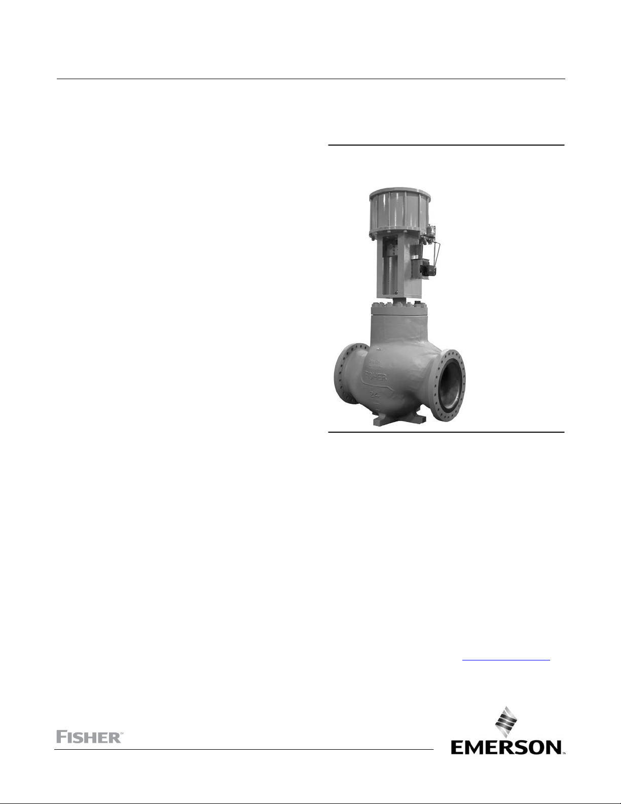
Figure 1. NPS 24 x 20 Fisher EWT Valve with Piston
Actuator and FIELDVUE™ DVC6200 Digital Valve
Controller
W9156‐2
Introduction
Scope of Manual
This instruction manual includes installation and maintenance information for NPS 12 through 24 x 20 CL150 through
600 Fisher EUD, EUT, EUT‐2, EWD, EWT, and EWT‐2 valves, and the NPS 12 and 20 x 16 CL900 EUD, EUT-2, EWD, and
EWT‐2 valves. (Size designations such as NPS 20 x 16 are end connection size x nominal trim size.)
Refer to separate manuals for instructions covering the actuator and accessories.
Do not install, operate, or maintain an EUD, EUT, EUT‐2, EWD, EWT, or EWT‐2 valve without being fully trained and
qualified in valve, actuator, and accessory installation, operation, and maintenance. To avoid personal injury or
property damage, it is important to carefully read, understand, and follow all the contents of this manual, including all
safety cautions and warnings. If you have any questions about these instructions, contact your Emerson sales office
Local Business Partner before proceeding.
www.Fisher.com
or

EU and EW Series Valves
July 2017
Table 1. Specifications
Instruction Manual
D102010X012
Valve Sizes
EUT, EUT‐2, and EUD: NPS J 12, J 16, J 20,
and J 16x20
EWT, EWT‐2, and EWD: NPS J 20x16, J 24x16, and
J 24x20 valves (size designations are end connection
size x nominal trim size)
End Connection Styles
(1)
Flanged: CL150, 300, 600, and 900
raised‐face or
ring‐type joint flanges per ASME B16.5
Buttwelding: All ASME B16.25 schedules through
schedule 120 that are compatible with the
ASME B16.34 valve body rating
For other end connections, contact your Emerson
sales office or Local Business Partner for details
Maximum Inlet Pressure and Temperature
(2)
Flanged: Consistent with CL150, 300, 600, and 900
pressure/temperature ratings per ASME B16.34
Buttwelding: Consistent with CL600 per ASME B16.34
Also see the Installation section
(1)
Shutoff Classifications per ANSI/FCI 70‐2 and IEC
60534‐4 (continued)
EUD and EWD with Metal Seats
Standard: Class III
Optional: Class IV and V (Bore Seal)
Flow Characteristics
Standard Cages: J Linear or J equal percentage
WhisperFlot, Whisper Trimt III, and Cavitrol III
Cages: Linear
Flow Direction
Standard and Cavitrol III Cages: Down
WhisperFlo and Whisper Trim III Cages: Up
Port Diameters
NPS 12 Trim: J 279.4 mm (11.00 inches),
NPS 16 Trim: J 355.6 mm (14 inches), J 374.7 mm
(14.75 inches), and J 412.8 mm (16.25 inches)
NPS 20 Trim: J 431.8 mm (17 inches), J 463.6 mm
(18.25 inches) and J 501.7 mm (19.75 inches)
Valve Plug Travel
102 through 432 mm (4 to 17 inches).
Contact your Emerson sales office or Local Business
Partner for further details if needed
Shutoff Classifications per ANSI/FCI 70‐2 and IEC
60534‐4
EUT, EUT‐2, EWT, and EWT‐2 with Metal Seats
Standard (for all trims except 2‐Stage Cavitrolt Trim):
Yoke Boss and Stem Diameters
J 127 mm (5‐inch) or J 127 mm (5H‐inch)
diameter yoke boss, each with 31.8 mm
(1‐1/4 inch) diameter valve stem
Class IV
Standard (for 2‐Stage Cavitrol Trim): Class V
Optional (for all trims except 2‐Stage Cavitrol Trim):
Approximate Weights
See table 6
Class V
EUT, EUT‐2, EWT, and EWT‐2 with Soft Metal Seats:
Class V
1. CL900 end connections are available only for NPS 16 and 20 x 16 EUD, EUT‐2, EWD, or EWT‐2 valves.
2. Do not exceed the pressure or temperature limits in this manual, on the equipment nameplate, and any applicable code limitations.
Educational Services
For information on available courses for the Fisher EU and EW Series, NPS 12 through 24x20 valves, as well as a variety
of other products, contact:
Emerson Automation Solutions
Educational Services - Registration
Phone: 1-641-754-3771 or 1-800-338-8158
E-mail: education@emerson.com
emerson.com/fishervalvetraining
2

Instruction Manual
D102010X012
Table 2. WhisperFlo Trim Specifications
EU and EW Series Valves
July 2017
Trim Material and Selection
J 316 Stainless Steel w/ hardfacing
J 410 Stainless Steel, hardened
J Others per application
Temperature Capability
J EUT and EWT: -73 to 316_C (-100 to 600_F)
J EUT‐2 and EWT‐2: -73 to 232_C (-100 to 450_F)
with adequate care and corrections in aerodynamic
noise prediction - consult your Emerson Automation
Solutions sales office
Flow Characteristic
Linear (restricted linear cages and special,
characterized cages are available‐‐consult your
Emerson Automation Solutions sales office)
J EUD and EWD: -29 to 538_C (-20 to 1000_F)
J Others per application
Rangeability
65:1
Maximum Pressure Drops
As shown in this bulletin. Also see Bulletin 80.3:010
WhisperFlo Aerodynamic Attenuation Trims
WhisperFlo Aerodynamic Trim Pressure Ratings
Up to 1500 psi drop
(1,2)
High rangeability in excess of 250:1 is available in
some constructions. Contact your Emerson sales
office or Local Business Partner for details
Flow Direction
Standard: Flow up‐‐through the seat ring and out
through the cage orifices
Velocity Limits
WhisperFlo trim is designed for 0.3 MACH as an
inherent outlet velocity limit. This velocity limit of 0.3
MACH may be exceeded for demanding applications
1. Other pressures on application.
2. The pressure/temperature limits in this instruction manual and in any applicable standard limitations should not be exceeded.
Noise Attenuation
Approximately -40 dBA maximum depending on the
nP/P
ratio per IEC 60534‐8‐3 calculation procedure
1
Description
All valve types covered in this manual (EUD, EUT, EUT‐2, EWD, EWT, and EWT‐2 valves) can be used for either
throttling or on‐off control of a wide variety of liquids and gasses. They are single‐port, globe‐style valves with cage
guiding, balanced valve plugs, and a push‐down‐to‐close action. EUT, EWT, and EWT‐2 valves have a spring‐loaded
PTFE seal between the plug and cage; the EUD and EWD valves have two graphite piston rings between the plug and
cage. See figure 5, 6, or 7 for seal details.
EUT‐2 and EWT‐2 valves have a seat ring threaded into the cage. A spring‐loaded PTFE seal is used to seal between the
seat ring and the valve body. Standard seating is metal‐to‐metal, but optional soft metal seats are also available. A
typical EUT‐2 or EWT‐2 valve is shown in figure 5.
EUD and EWD valves have a seat ring bolted into the valve body with cap screws. Seating is metal‐to‐metal. A typical
EUD or EWD valve is shown in figure 6.
EUT and EWT valves have a seat ring bolted into the valve body with cap screws. These valves have metal‐to‐metal
seating and use PEEK anti‐extrusion rings in the plug seal arrangement to increase the upper temperature limit of the
seal to 316_C (600_F). A typical EUT valve is shown in figure 7.
Cavitrol III, Whisper Trim III, and WhisperFlo trim cages are available in these valves. Cavitrol trim helps eliminate
cavitation damage in liquid service in a properly sized valve and Whisper Trim III and WhisperFlo trim cages help
attenuate aerodynamic noise in gas service.
Fisher WhisperFlo trim represents state of the art solutions for applications that demand ultimate aerodynamic noise
attenuation.
3

EU and EW Series Valves
July 2017
Instruction Manual
D102010X012
Control valves with WhisperFlo cages provide additional aerodynamic noise attenuation in very demanding vapor or
gas applications with high‐pressure drops. A WhisperFlo cage with an appropriately sized valve body is designed to
reduce the noise level up to -40 dBA. For special applications, -50 dBA attenuation can be achieved.
Specifications
Typical specifications for these valves are shown in tables 1 and 2. Some of the specifications for a given valve
assembly as it comes from the factory appear on the actuator nameplate if the valve is part of a complete control valve
assembly.
Installation
WARNING
To avoid personal injury or property damage resulting from the sudden release of pressure, do not install the valve
assembly where service conditions could exceed the limits given in this manual or on the appropriate nameplates. Use
pressure‐relieving devices as required by government or accepted industry codes and good engineering practices.
Always wear protective gloves, clothing, and eyewear when performing any installation operations to avoid personal
injury.
Check with your process or safety engineer for any additional measures that must be taken to protect against process
media.
If installing into an existing application, also refer to the WARNING at the beginning of the Maintenance section in this
instruction manual.
CAUTION
The valve configuration and construction materials were selected to meet particular pressure, temperature, pressure drop,
and controlled fluid conditions. Because some valve body/trim material combinations are limited in their pressure drop and
temperature range capabilities, do not apply any other conditions to the valve without first contacting your Emerson sales
office or Local Business Partner.
WARNING
If you are hoisting the valve, use nylon slings to protect the surfaces.
Carefully position the slings to prevent damage to the actuator tubing and any accessories. Also, take care to prevent
people from being injured in case the hoist or rigging slips unexpectedly. Refer to table 6 for valve assembly weights. It is
important to use adequately sized hoists and chains or slings to handle the valve.
1. Before installing the valve, inspect the valve and associated equipment for any damage and any foreign material.
2. Make certain that the valve body interior is clean, that pipelines are free of foreign material, and the valve is
oriented so that pipeline flow is in the same direction as the arrow on the side of the valve.
CAUTION
For long service life and more effective operation, the process liquid must be clean. If the valve being installed has a
Whisper Trim, WhisperFlo, or Cavitrol Trim cage with small internal flow passages, impurities or entrained solids in the
4

Instruction Manual
D102010X012
process liquid may cause irreparable erosion damage to the seating surfaces and may plug cage holes and passages,
causing cavitation damage. During valve installation or the plant cleaning cycle, install a strainer upstream from the valve
to help free pipelines of foreign material.
EU and EW Series Valves
July 2017
3. The control valve assembly may be installed in any orientation unless limited by seismic criteria. However, the
normal method is with the actuator vertical above the valve. Other positions may result in uneven valve plug and
cage wear and in improper operation. Support the actuator if it is not installed in the vertical position. For more
information, consult your Emerson sales office
or Local Business Partner.
4. Use accepted piping and welding practices when installing the valve in the line. You can leave internal elastomeric
parts in place when welding. For flanged valves, use a suitable gasket between the valve and pipeline flanges.
CAUTION
Depending on valve body materials used, post weld heat treating might be required. If so, damage to internal elastomeric
and plastic parts, as well as internal metal parts is possible. Shrunk‐fit pieces and threaded connections might also loosen. If
post weld heat treating is to be performed, all trim parts should be removed. Contact your Emerson sales office or Local
Business Partner for additional information.
5. With a leak‐off bonnet construction, remove the 1/4 NPT pipe plugs (key 14, figure 4) from the bonnet to hook up
the leak‐off piping.
6. If continuous operation of the plant is required during inspection or maintenance of the valve, install a three‐valve
bypass around the control valve assembly.
7. If the actuator and valve are shipped separately, refer to the actuator mounting procedure in the appropriate
actuator instruction manual.
WARNING
Personal injury could result from packing leakage. Valve packing was tightened before shipment; however some
readjustment will be required to meet specific service conditions.
If the valve has ENVIRO‐SEALt live‐loaded packing or HIGH‐SEAL ULF live‐loaded packing installed, this initial
re‐adjustment will probably not be required. See the Fisher instruction manuals titled ENVIRO‐SEAL Packing System for
Sliding‐Stem Valves (D101642X012
) or HIGH‐SEAL ULF Live‐Loaded Packing System (D101453X012) (as appropriate)
for packing instructions.
Maintenance
Valve parts are subject to normal wear and must be inspected and replaced as necessary. Inspection and maintenance
frequency depends on the severity of service conditions. This section includes instructions for packing lubrication,
packing maintenance, trim maintenance, lapping seating surfaces, and valve plug maintenance. All maintenance
operations may be performed with the valve in the line.
WARNING
Avoid personal injury from sudden release of process pressure. Before performing any maintenance operations:
5

EU and EW Series Valves
July 2017
Instruction Manual
D102010X012
D Do not remove the actuator from the valve while the valve is still pressurized.
D Always wear protective gloves, clothing, and eyewear when performing any maintenance operations to avoid personal
injury.
D Disconnect any operating lines providing air pressure, electric power, or a control signal to the actuator. Be sure the
actuator cannot suddenly open or close the valve.
D Use bypass valves or completely shut off the process to isolate the valve from process pressure. Relieve process pressure
on both sides of the valve. Drain the process media from both sides of the valve.
D Vent the power actuator loading pressure and relieve any actuator spring precompression.
D Use lock‐out procedures to be sure that the above measures stay in effect while you work on the equipment.
D The valve packing box may contain process fluids that are pressurized, even when the valve has been removed from the
pipeline. Process fluids may spray out under pressure when removing the packing hardware or packing rings, or when
loosening the packing box pipe plug.
D Check with your process or safety engineer for any additional measures that must be taken to protect against process
media.
1. Isolate the control valve from the line pressure, release pressure from both sides of the valve body, and drain the
process media from both sides of the valve. If using a power actuator, also shut off all pressure lines to the power
actuator, release all pressure from the actuator, and use lock‐out procedures to prevent injury while you work on
the equipment.
Figure 2. Lubricator and Lubricator/Isolating Valve
31
LUBRICATOR
31
10A9421‐A
AJ5428‐D
A0832‐2
Note
Whenever a gasket seal is disturbed by removing or shifting gasketed parts, a new gasket should be installed upon reassembly.
This is necessary to ensure a good gasket seal because the used gasket might not seal properly.
LUBRICATOR/ISOLATING VALVE
Note
If the valve has ENVIRO‐SEAL live‐loaded packing or HIGH‐SEAL ULF live‐loaded packing installed, see the Fisher instruction
manuals titled ENVIRO‐SEAL Packing System for Sliding‐Stem Valves (D101642X012
System (D101453X012
6
) (as appropriate) for packing instructions.
) or HIGH‐SEAL ULF Live‐Loaded Packing

Instruction Manual
D102010X012
Figure 3. Typical Packing
UPPER WIPER
(KEY 12)
PACKING
FOLLOWER
(KEY 13)
WASHER
(KEY 10)
SPRING
(KEY 8)
PACKING BOX
RING (KEY 11)
FOR S31600 OR S17400 SST
METAL PACKING BOX PARTS
FEMALE
ADAPTOR
PACKING RING
MALE
ADAPTOR
LOWER WIPER
FEMALE
ADAPTOR
PACKING RING
MALE
ADAPTOR
LOWER
WIPER
FOR ALL OTHER METAL PACKING
PTFE V-RING SINGLE ARRANGEMENTS
EU and EW Series Valves
BOX PART MATERIALS
UPPER WIPER
(KEY 12)
PACKING
FOLLOWER
(KEY 13)
SPACER (KEY 8)
PACKING BOX
RING (KEY 11)
July 2017
FEMALE
ADAPTOR (KEY 32)
ASSEMBLY 1
(POSITIVE
PRESSURES)
ASSEMBLY 2
(VACUUM)
ASSEMBLY 3
(POSITIVE
PRESSURES &
VACUUM)
31.8 mm
(1-1/4 INCH) STEM
PTFE V-RING
DOUBLE ARRANGEMENTS
NOTE:
PACKING SET (KEY 6) (2 REQUIRED FOR DOUBLE ARRANGEMENTS
B2398
UPPER WIPER
(KEY 12)
PACKING
FOLLOWER
(KEY 13)
MALE
ADAPTOR (KEY 31)
PACKING RING (KEY 7)
LANTERN
RING
(KEY 8)
PACKING BOX
RING (KEY 11)
LOWER
WIPER
UPPER WIPER
(KEY 12)
PACKING
FOLLOWER
(KEY 13)
PACKING RING (KEY 7)
LANTERN
RING
(KEY 8)
PACKING BOX
RING (KEY 11)
31.8 mm
(1-1/4 INCH) STEM
PTFE/COMPOSITION
ARRANGEMENT
7

EU and EW Series Valves
July 2017
Figure 3. Typical Packing (Continued)
PACKING
FOLLOWER
(KEY 13)
GRAPHITE RIBBON
PACKING RING (KEY 7)
PACKING
FOLLOWER
(KEY 13)
GRAPHITE RIBBON
PACKING RING (KEY 7)
Instruction Manual
D102010X012
GRAPHITE FILAMENT
PACKING RING (KEY 7)
LANTERN
RING (KEY 8)
PACKING BOX
RING (KEY 11)
31.8 mm
(1-1/4 INCH) STEM
SINGLE ARRANGEMENT
31.8 mm
(1-1/4 INCH) STEM
DOUBLE ARRANGEMENT
GRAPHITE FILAMENT
PACKING RING (KEY 7)
LANTERN
RING (KEY 8)
PACKING BOX
RING (KEY 11)
GRAPHITE RIBBON/FILAMENT PACKING
NOTE:
0.102 mm (0.004 INCH) THICK SACRIFICIAL ZINC WASHERS:
USE ONLY ONE BELOW EACH GRAPHITE RIBBON RING
A6060
Packing Lubrication
CAUTION
Do not lubricate graphite packing. Graphite packing is self-lubricated. Additional lubrication may result in slip-stick
movement of the valve.
If a lubricator or lubricator/isolating valve (figure 2) is provided for PTFE/composition or other packings that require
lubrication, it will be installed in place of the 1/4 NPT pipe plug (key 14, figure 4). Use a silicon‐base lubricant. To
operate the lubricator, turn the cap screw clockwise to force the lubricant into the packing box. The
lubricator/isolating valve operates the same way except the isolating valve must first be opened and then closed after
lubrication is completed.
Packing Maintenance
This procedure does not cover ENVIRO‐SEAL or HIGH‐SEAL packing; refer to separate manuals for instructions on those
packing types.
Key numbers are shown in figure 3 unless otherwise indicated.
For spring‐loaded single PTFE V‐ring packing, the spring (key 8) maintains a sealing force on the packing. If leakage is
noted around the packing follower (key 13), check to be sure the shoulder on the packing follower is touching the
bonnet. If the shoulder is not touching the bonnet, tighten the packing flange nuts (key 5, figure 4) until the shoulder
is against the bonnet. If leakage cannot be stopped in this manner, proceed to the Replacing Packing section.
If there is undesirable packing leakage with other than spring‐loaded packing, first try to limit the leakage and
establish a stem seal by tightening the packing flange nuts.
If the packing is relatively new and tight on the stem and if tightening the packing flange nuts does not stop the
leakage, it is possible that the valve stem is worn or nicked so that a seal cannot be made. The surface finish of a new
8

Instruction Manual
D102010X012
EU and EW Series Valves
July 2017
valve stem is critical for making a good packing seal. If the leakage comes from the outside diameter of the packing, it
is possible that the leakage is caused by nicks or scratches around the packing box wall. If performing any of the
following procedures, inspect the valve stem and packing box wall for nicks and scratches.
Replacing Packing
1. Isolate the control valve from the line pressure, release pressure from both sides of the valve body, and drain the
process media from both sides of the valve. If using a power actuator, also shut off all pressure lines to the power
actuator, release all pressure from the actuator, and use lock‐out procedures to prevent injury while you work on
the equipment.
2. Remove any leak‐off piping from the bonnet. Disconnect the stem connector, and then remove the actuator from
the valve by unscrewing the hex nuts (key 26, figure 4).
3. Loosen the packing flange nuts (key 5, figure 4) so that the packing is not tight on the valve stem. Remove any
travel indicator parts and stem locknuts from the valve stem threads.
CAUTION
Avoid damage to the seating surfaces caused by the valve plug and stem assembly dropping from the bonnet after being
lifted part way out.
When lifting the bonnet (key 1, figure 4), either be sure that the valve plug and stem assembly remains in the valve and on
the seat or, temporarily install a valve stem locknut on the valve stem. This locknut will prevent the valve plug and stem
assembly from dropping out of the bonnet.
WARNING
To avoid personal injury or property damage caused by uncontrolled movement of the bonnet, loosen the bonnet by
following the instructions in the next step. Do not remove a stuck bonnet by pulling on it with equipment that can stretch
or store energy in any other manner. The sudden release of stored energy can cause uncontrolled movement of the bonnet.
If the cage sticks to the bonnet, proceed carefully with bonnet removal.
Note
The following step also provides additional assurance that the valve body fluid pressure has been relieved.
4. Hex nuts (key 16, figures 5 or 6) attach the bonnet to the valve body. Loosen these nuts or cap screws
approximately 3 mm (1/8 inch). Then loosen the body‐to‐bonnet gasketed joint by either rocking the bonnet or
prying between the bonnet and valve body. Work the prying tool around the bonnet until the bonnet loosens. If no
fluid leaks from the joint, remove the nuts completely and carefully lift the bonnet (key 1, figure 4).
5. Set the bonnet on a protective surface to prevent damage to the bonnet gasket surface.
6. Whenever the bonnet has been removed, replace the bonnet gasket and the cage gasket (keys 10 and 11, figures 5
and 6). Remove the bonnet gasket.
7. Lift the valve plug and stem assembly out of the valve body and set it on a protective surface. If the valve plug is to
be reused, protect the valve plug seating surface to prevent scratches.
8. Install screws or bolts into the tapped holes in the top of the cage assembly (key 3), and carefully lift it out of the
valve body. Remove the cage gasket (key 11).
9. If further trim maintenance is required, refer to the Trim Maintenance section.
9

EU and EW Series Valves
July 2017
Figure 4. Typical Globe Valve Bonnet
Instruction Manual
D102010X012
CU4317
Table 3. Packing Flange Nut Torque for Packing Without a Spring
VALVE STEM
DIAMETER
mm Inch NSm LbfSft NSm LbfSft NSm LbfSft NSm LbfSft
31.8 1‐1/4
PRESSURE
RATING
CL150 & 300
CL600
CL900
Minimum Torque Maximum Torque Minimum Torque Maximum Torque
33
45
56
GRAPHITE‐TYPE PACKING PTFE‐TYPE PACKING
24.3
33.2
41.3
49
67
83
36.1
49.4
61.2
16
21
27
11.8
15.5
19.9
25
33
41
18.4
24.3
30.2
Table 4. Body‐to‐Bonnet Bolt Torque
VALVE SIZE,
NPS
12, 16x12
16
16
20 x 16, 24 x 16
20 x 16
20, 24 x 20
1. For B7, B7M, B16, and 660 bolting materials. For other materials, contact your Emerson sales office or Local Business Partner for torque values.
PRESSURE RATING
CL150 - 600
CL150 ‐ 600
CL900
CL150 ‐ 600
CL900
CL150 ‐ 600
NSm LbfSft
1750
2800
1750
2800
1750
4240
BOLTING TORQUE
(1)
1290
2070
1290
2070
1290
3130
CAUTION
To prevent damage to the valve cavity, packing box wall, and packing surfaces, observe the instructions in the next three
steps.
10

Instruction Manual
D102010X012
EU and EW Series Valves
July 2017
10. Cover the opening in the valve body to protect the gasket surface and prevent foreign material from getting into
the valve cavity.
11. Remove the packing flange nuts, packing flange, upper wiper, and packing follower (keys 5, 3, 12, and 13, figure
4). Carefully push out all the remaining packing parts from the valve side of the bonnet using a rounded rod or other
tool that will not scratch the packing box wall. Clean the packing box and the metal packing parts.
12. Inspect the valve stem threads and packing box surfaces for any sharp edges that might cut the packing. Scratches
or burrs could cause packing box leakage or damage to the new packing. If the surface condition cannot be
improved by light sanding or honing with a tool similar to an automotive brake‐cylinder hone, replace the damaged
parts.
13. Remove the covering protecting the valve cavity, and install a new cage gasket (key 11, figure 5 and 6), making
sure the gasket seating surfaces are clean and smooth.
14. Re‐install the trim parts by following the Trim Replacement section. Install a new bonnet gasket (key 10, figure 5
and 6).
Note
Proper performance of the tightening procedures in step 15 compresses the bonnet and cage gaskets (keys 10 and 11, figure 5
and 6) enough to seal the body‐to‐bonnet joint.
The bolting procedures in step 15 include‐‐but are not limited to‐‐ensuring that bolting threads are clean and evenly tightening
the hex nuts onto the studs in a crisscross pattern. Because of the boltup characteristics of the gaskets, tightening one nut may
loosen an adjacent nut. Repeat the crisscross tightening pattern several times until each nut is tight and the body‐to‐bonnet seal is
made.
Note
Stud(s) and nut(s) should be installed such that the manufacturer's trademark and material grade marking is visible, allowing easy
comparison to the materials selected and documented in the Emerson/Fisher serial card provided with this product.
WARNING
Personal injury or damage to equipment could occur if improper stud and nut materials or parts are used. Do not operate or
assemble this product with stud(s) and nut(s) that are not approved by Emerson/Fisher engineering and/or listed on the
serial card provided with this product. Use of unapproved materials and parts could lead to stresses exceeding the design
or code limits intended for this particular service. Install studs with the material grade and manufacturer's identification
mark visible. Contact your Emerson representative immediately if a discrepancy between actual parts and approved parts
is suspected.
15. Lubricate the stud bolts (key 15, figure 5 and 6) with anti‐seize lubricant, slide the bonnet over the stem and onto
the bolts, and secure with the stud bolt nuts (key 16, figure 5 and 6), using accepted bolting procedures during
tightening so that the body‐to‐bonnet joint will withstand test pressures and application service conditions. Refer
to table 4 for bolting torque guidelines.
16. Install new packing and the metal packing box parts according to the appropriate arrangement in figure 3. Place a
smooth‐edged pipe over the valve stem, and gently tap each soft packing part into the packing box one piece at a
time, being sure that air is not trapped between adjacent soft parts.
17. Slide the packing follower, upper wiper, and packing flange (keys 13, 12, and 3, figure 4) into position. Lubricate
the packing flange studs (key 4, figure 4) and the faces of the packing flange nuts (key 5, figure 4). Replace the
packing flange nuts.
11

EU and EW Series Valves
July 2017
18. For spring‐loaded PTFE V‐ring packing, tighten the packing flange nuts until the shoulder on the packing follower
(key 13, figure 4) contacts the bonnet.
For graphite packing, tighten the packing flange nuts to the maximum recommended torque shown in table 3. Then,
loosen the packing flange nuts and retighten them to the recommended minimum torque shown in table 3.
For other packing types, tighten the packing flange nuts alternately in small, equal increments until one of the nuts
reaches the minimum recommended torque shown in table 3. Then, tighten the remaining flange nut until the
packing flange (key 3, figure 4) is at a 90‐degree angle to the valve stem.
19. Mount the actuator on the valve assembly, and reconnect the actuator and valve stem according to the procedure
in the appropriate actuator instruction manual. Check for leakage around the packing follower when the valve is
being put into service. Retighten the packing flange nuts as required.
Instruction Manual
D102010X012
Trim Maintenance
Trim Removal
Except where indicated, key numbers in this section are shown in figure 5 for EUT‐2 and EWT‐2 valves and in figure 6
for EUD and EWD valves.
1. Isolate the control valve from the line pressure, release pressure from both sides of the valve body, and drain the
process media from both sides of the valve. If using a power actuator, also shut off all pressure lines to the power
actuator, release all pressure from the actuator, and use lock‐out procedures to prevent injury while you work on
the equipment.
2. Remove the actuator and the bonnet according to steps 2 through 5 of the Replacing Packing Section.
CAUTION
Use care to avoid damaging gasket surfaces.
The surface finish of the valve stem (key 7) is critical for making a good packing seal. The inside surface of the cage or cage
assembly (key 3) is critical for smooth operation of the valve plug and for making a seal with the seal ring (key 28). The
seating surfaces of the valve plug (key 2) and seat ring (key 9) are critical for proper shutoff. Assume all these parts are in
good condition, and protect them accordingly unless inspection reveals otherwise.
3. Packing parts can be removed if desired. Replace these parts as described in the Packing Replacement section.
4. Lift the valve plug and stem assembly out of the valve body and set it on a protective surface. If the valve plug is to
be reused, protect the valve plug seating surface to prevent scratches.
5. Install screws or bolts into the tapped holes in the top of the cage assembly (key 3), and carefully lift it out of the
valve body. Remove the gaskets (keys 10 and 11).
6. Proceed as appropriate:
For EUT‐2 or EWT‐2 valves (figure 5), the valve has a seat ring seal ring (key 6). Inspect this seal ring, and remove it if
replacement is necessary. The seat ring is screwed into the cage and secured with two tack welds, one on each side of
the cage. Remove the tack welds by grinding or filing them off.
D For all sizes except NPS 12 and 16x12, there are slots cut in the seat ring. Insert a bar through the slots and turn the
seat ring out of the cage.
D For NPS 12 and 16x12, there are two 3/8 inch UNC tapped holes in the bottom of the seat ring. Screw cap screws
into these holes. Use a bar to pry against the cap screws and turn the seat ring out of the cage.
12

Instruction Manual
D102010X012
EU and EW Series Valves
July 2017
For EUD, EWD, EUT, and EWT valves (figure 6), unscrew the seat ring cap screws (key 49). Install screws or bolts into
the tapped holes in the top of the seat ring (key 9) and carefully lift it out of the valve body. Remove the gasket
(key 13).
7. Inspect parts for wear or damage that would prevent proper operation of the valve. Replace or repair trim parts
according to the following Lapping Seating Surfaces or Valve Plug Maintenance procedures as appropriate.
Lapping Seating Surfaces
A certain amount of leakage should be expected with metal‐to‐metal seating in any valve body. If the leakage
becomes excessive, however, the condition of the seating surfaces of the valve plug and seat ring can be improved by
lapping. (Deep nicks should be machined out rather than ground out.) Use a good quality lapping compound of a
mixture of 280 to 600‐grit. Apply the compound to the bottom of the valve plug.
Assemble the valve to the extent that the cage or cage assembly is in place and the bonnet is bolted to the valve body.
A simple handle can be made from a piece of strap iron locked to the valve plug stem with nuts. Rotate the handle
alternately in each direction to lap the seats. After lapping, remove the bonnet, and clean the seat surfaces.
Completely assemble the valve as described in the Trim Replacement section, and test the valve for shutoff. Repeat
the lapping procedure if leakage is still excessive.
Valve Plug Maintenance
Except where indicated, key numbers in this section are shown in figure 5 for EUT‐2 and EWT‐2 valves and in figure 6
for EUD and EWD valves.
CAUTION
For valves with a PTFE seal ring (figure 5, 6, or 7), if replacing the valve plug seal ring (key 28), be careful not to scratch the
surfaces of the ring groove in the valve plug or any of the surfaces of the replacement ring, or the replacement ring may not
seal properly.
1. Remove the valve plug (key 2) according to the Disassembly section.
2. For seal‐ring constructions, carefully pry or cut the seal ring (key 28, figure 5, 6, or 7) from its groove in the plug.
Install the replacement spring‐loaded seal ring with the open side facing the top or bottom of the valve plug,
depending on flow direction. The open side of the seal ring should face up (toward the actuator) in flow‐up
installations and down in flow‐down installations.
To install the seal ring, first lubricate it with general‐purpose, lithium‐base lubricant. Then gently stretch the seal ring
and work it over the top edge of the valve plug. Give the PTFE material in the seal ring time to cold flow during the
stretching procedure. Avoid jerking sharply on the ring. Stretching the seal ring over the valve plug might make it
seem loose when it is in the groove, but it will shrink to its original size after you have installed the plug into the cage.
3. For piston‐ring constructions, each of the piston rings (key 28, figure 5, 6, or 7) is in two halves; remove the halves.
Each new graphite piston ring is furnished as a complete ring, and each must be broken into two approximately equal
portions. Do this by placing the ring on edge on a smooth, hard surface and striking the ring squarely with a hammer.
Be sure to match the broken ends when installing the ring sections in the valve plug grooves.
13

EU and EW Series Valves
July 2017
Figure 5. Typical Fisher EUT‐2 or EWT‐2 Valve
A
Instruction Manual
CAGE
(KEY 3)
VIEW A
EUT‐2 AND EWT‐2 VALVE PLUGS
SEAL RING FOR
D102010X012
VALVE
PLUG
(KEY 2)
SEAL
RING
(KEY 28)
E1488
NOTE:
SEAL RING OPENING MUST FACE SEAT RING FOR FLOW DOWN APPLICATIONS AND MUST FACE ACTUATOR FOR FLOW UP APPLICATIONS
1
CAUTION
Never reuse an old stem (key 7) with a new valve plug. Using an old stem with a new plug requires drilling a new pin hole in
the stem. This weakens the stem and may cause it to fail in service. However, a used valve plug may be reused with a new
stem.
4. To replace the valve stem (key 7), drill out the pin (key 8) and unscrew the stem from the valve plug.
14

Instruction Manual
D102010X012
EU and EW Series Valves
July 2017
5. Screw the new stem tightly into the valve plug. Drill through the stem, using a 1/4‐inch diameter drill for the 31.8
mm (1‐1/4 inch) stem diameter used in this valve. Use the hole in the valve plug as a guide. Remove any chips or
burrs, and drive in a new pin to lock the assembly.
Trim Replacement
Except where indicated, key numbers are shown in figure 5 and 6.
1. Proceed as appropriate:
For EUT‐2 or EWT‐2 valves:
For all sizes except NPS 12 and 16x12, turn the seat ring (key 9) into the cage (key 3) with a bar inserted through the seat
ring slots.
For NPS 12 and 16x12, insert cap screws into the two 3/8 inch UNC tapped holes in the bottom of the seat ring (key 9).
Use a bar to pry against the cap screws and turn the seat ring (key 9) into the cage (key 3).
For all sizes, tack weld the seat ring to the cage using minimal heat. Two welds, 6 mm (1/4‐inch) long and 180 degrees
apart, are required. Install the seat ring seal ring (key 6) so that its open side faces the valve stem for Cavitrol III trim
and flow‐down standard cages. Reverse the seal ring for Whisper Trim III, WhisperFlo, and flow‐up standard cages.
Lubricate the seal ring with a general‐purpose, lithium‐base lubricant, and place it over the bottom end of the seat
ring. Start the ring in the groove on one side of the seat ring, and gently work it over the seat ring.
For EUD and EWD valves (figure 6) and EUT and EWT valves (figure 7), install the seat ring gasket (key 13).
Temporarily install screws or bolts into the tapped holes in the seat ring (key 9), making sure the seating surface is
facing up. Lower the seat ring into the valve body. Remove the temporary screws or bolts.
Secure the seat ring (key 9) with the cap screws (key 49). Tighten the cap screws in a criss‐cross pattern to a torque of
39 NSm (29 lbfSft) for NPS 12 and NPS 16x12 valves and to 92 NSm (68 lbfSft) for NPS 16 through NPS 24x20 valves.
2. Install a cage gasket (key 11) into the valve. Temporarily install screws or bolts into the tapped holes in the top of
the cage assembly (key 3) to help while installing this piece into the valve. Any rotational orientation of the cage or
assembly with respect to the valve is acceptable.
For EUT‐2 and EWT‐2 valves, use care to avoid damaging the seat ring seal ring and cage seating surfaces while
handling the heavy parts. To help insert the cage or assembly into the valve, lubricate the outside diameter of the seat
ring seal ring with lithium grease.
3. Slide the valve plug (key 2) and stem assembly into the cage.
For valves with a seal ring, make sure the valve plug seal ring (key 28) is evenly engaged in the entrance chamfer at the
top of the cage or cage assembly to avoid damaging the ring.
For valves with piston rings, make sure the rings are fully engaged into the piston ring groove and flush with the
outside diameter of the plug.
4. Install the bonnet gasket (key 10).
CAUTION
If the packing is to be reused and was not removed from the bonnet, use care when installing the bonnet to avoid
damaging the packing with the valve stem threads.
5. Mount the bonnet on the valve, and complete assembly according to steps 15 through 19 of the Replacing Packing
section, omitting steps 16 and 17 if new packing is not being installed and being sure to observe the note before
step 15.
15

EU and EW Series Valves
July 2017
Figure 6. Typical Fisher EUD Valve
Instruction Manual
D102010X012
CAGE
(KEY 3)
VALVE
PLUG
(KEY 2)
PISTON
RINGS
(KEY 28)
VIEW A
PISTON RINGS FOR
EUD AND EWD VALVE PLUGS
A
16
APPLY LUB
B2411
B2411-1

Instruction Manual
D102010X012
Figure 7. Typical Fisher EUT or EWT Valve with HTS1 Option
27
EU and EW Series Valves
July 2017
2
2
27
29
29
28
28
FLOW UP
21B2120-A
A6137
A
PEEK ANTI‐EXTRUSION RINGS
VIEW A
SEAL RING FOR EUT AND EWT
VALVE PLUGS
FLOW DOWN
E1489
17

EU and EW Series Valves
July 2017
Figure 8. Fisher EUD and EWD with Bore Seal Trim
RETAINER
PISTON RING
RETAINER
Instruction Manual
D102010X012
PISTON RING
CAGE
SEATING AREA
BORE SEAL
PLUG
FLOW DOWN
CAGE
SEATING AREA
PLUG
BORE SEAL
FLOW UP
Retrofit: Installing Bore Seal Trim
Note
Additional actuator thrust is required for a valve with Bore Seal trim. When installing Bore Seal trim in an existing valve, contact
your Emerson sales office
or Local Business Partner for assistance in determining new actuator thrust requirements.
Assemble the new valve plug/retainer assembly (with Bore Seal plug seal) using the following instructions:
CAUTION
To avoid leakage when the valve is returned to service, use appropriate methods and materials to protect all sealing
surfaces of the new trim parts while assembling the individual parts and during installation in the valve body.
1. Apply a suitable high‐temperature lubricant to the inside diameter of the Bore Seal plug seal. Also, lubricate the
outside diameter of the valve plug where the Bore Seal plug seal must be pressed into the proper sealing position
(figure 8).
2. Orient the Bore Seal plug seal for correct sealing action based on the process fluid flow direction through the valve.
D The open interior of the Bore Seal plug seal must face up in a valve with flow‐up construction (figure 8).
D The open interior of the Bore Seal plug seal must face down in a valve with flow‐down construction (figure 8).
3. Place the Bore Seal plug seal over the top of the valve plug. The retainer will help guide the Bore Seal down onto the
plug (figure 8). Do not force the Bore Seal over the plug. For flow down constructions, skip to step 5.
4. An installation tool (see table 5) must be inserted into the Bore Seal prior to using the retainer to guide it down the
plug.
18

Instruction Manual
D102010X012
Figure 9. Bore Seal Installation Tool
EU and EW Series Valves
July 2017
GE22109-A
F
G
H
E
A
B
C
D
Table 5. Bore Seal Installation Tool Dimensions
VALVE
PORT SIZE,
INCH
10.00 10.12 9.7 9.80-9.82 10.02-10.00 0.10 0.10 0.32 R.06 GE17914X012
11.00
14.00
14.75 14.84 14.424-14.416 14.516-14.536 14.736-14.716 0.10 0.10 0.32 R.05 GE34073X012
16.25
18.25
19.75
1. For sizes, contact your Emerson sales office.
A B C D E F G H
Dimensions, Inches (See Figure 9)
(1)
(1)
(1)
(1)
(1)
Tool Part
Number
n/a
n/a
n/a
n/a
n/a
5. Apply a suitable high‐temperature lubricant to the threads on the plug. Then, place the Bore Seal retainer onto the
plug and tighten the retainer using an appropriate tool such as a strap wrench. For flow down constructions, skip to
step 7.
6. Remove the retainer and then the installation tool. Place the Bore Seal retainer back onto the plug and tighten the
retainer using an appropriate tool such as a strap wrench.
7. Using an appropriate tool such as a center punch, stake the threads on top of the plug in one place (figure 10) to
secure the Bore Seal retainer.
8. Install the new plug/retainer assembly with Bore Seal on the new stem following the appropriate instructions in the
Trim Replacement section of this manual.
9. Install piston rings by following instructions in the Trim Replacement section of this manual.
10. Remove the existing valve actuator and bonnet following the appropriate instructions in the Replacing Packing
section of this manual.
19

EU and EW Series Valves
July 2017
Instruction Manual
D102010X012
CAUTION
Do not remove the existing valve stem from the valve plug unless you are planning to replace the valve stem.
Never reuse an old valve stem with a new plug or reinstall a valve stem after it has been removed. Replacing a valve stem
requires drilling a new pin hole in the stem. This drilling weakens the stem and may cause failure in service. However, a
used valve plug may be reused with a new valve stem.
11. Remove the existing valve stem and plug, cage, and seat ring from the valve body following the appropriate
instructions in the Trim Removal section of this manual.
12. Replace all gaskets according to appropriate instructions in the Trim Replacement section of this manual.
13. Install the new seat ring, cage, valve plug/retainer assembly, and stem into the valve body and completely
reassemble the valve package following the appropriate instructions in the Trim Replacement section of this
manual.
CAUTION
To avoid excessive leakage and seat erosion, the valve plug must be initially seated with sufficient force to overcome the
resistance of the Bore Seal and contact the seat ring. You can correctly seat the valve plug by using the same force
calculated for full load when sizing your actuator. With no pressure drop across the valve, this force will adequately drive
the valve plug to the seat ring, thus giving the Bore Seal a predetermined permanent set.
With full actuator force applied and the valve plug fully seated, align the actuator travel indicator scale with the lower end
of valve travel. Refer to the appropriate actuator instruction manual for information on this procedure.
Replacement of Installed Bore Seal Trim
Trim Removal (Bore Seal Constructions)
1. Remove the valve actuator and bonnet following the appropriate instructions in the Replacing Packing section of
this manual.
CAUTION
To avoid leakage when the valve is returned to service, use appropriate methods and materials to protect all sealing
surfaces of the trim parts during maintenance.
Use caution when removing piston ring(s) and the Bore Seal to avoid scratching any sealing surface.
CAUTION
Do not remove the valve stem from the plug/retainer assembly unless you are planning to replace the valve stem.
Never reuse an old valve stem with a new plug or reinstall a valve stem after it has been removed. Replacing a valve stem
requires drilling a new pin hole in the stem. This drilling weakens the stem and may cause failure in service. However, a
used valve plug may be reused with a new valve stem.
2. Remove the plug/retainer assembly (with Bore Seal), cage, and seat ring from the valve body following the
appropriate instructions in the Trim Removal section of this manual.
3. Locate the staked thread on top of the valve plug (figure 10). The staked thread secures the retainer. Use a drill with
a 1/8 inch bit to drill out the staked area of the thread. Drill approximately 1/8 inch into the metal to remove the
staking.
20

Instruction Manual
D102010X012
EU and EW Series Valves
July 2017
Figure 10. Stake the Threads of the Bore Seal Retainer
DEFORM THREAD TO STAKE
Bore Seal RETAINER
PISTON
RING
RETAINER
Bore Seal
METAL
PLUG
SEAL
A6779
FLOW DOWN
VALVE
PLUG
4. Locate the break between sections of the piston ring(s). Using an appropriate tool such as a flat‐blade screwdriver,
carefully pry out the piston ring from the groove in the Bore Seal retainer.
5. After removing the piston ring, locate the 1/4‐inch diameter hole in the groove.
6. Select an appropriate tool such as a punch and place the tip of the tool into the hole with the body of the tool held
tangent to the outside diameter of the retainer. Strike the tool with a hammer to rotate the retainer and free it from
the valve plug. Remove the retainer from the plug.
7. Use an appropriate tool such as a flat‐blade screwdriver to pry the Bore Seal plug seal off the plug. Use caution to
avoid scratches or other damage to the sealing surfaces where the Bore Seal plug seal makes contact with the valve
plug (figure 11).
8. Inspect the lower seating surface where the valve plug contacts the seat ring for wear or damage which would
prevent proper operation of the valve. Also, inspect the upper seating surface inside the cage where the Bore Seal
plug seal contacts the cage, and inspect the sealing surface where the Bore Seal plug seal makes contact with the
plug (figure 11).
9. Replace or repair trim parts according to the following procedure for lapping metal seats, remachining metal seats,
or other valve plug maintenance procedures as appropriate.
Lapping Metal Seats (Bore Seal Constructions)
Before installing a new Bore Seal plug seal, lap the lower seating surface (valve plug to seat ring, figure 11) following
appropriate procedures in the Lapping Seats section of this manual.
Remachining Metal Seats (Bore Seal Constructions)
A valve plug with a Bore Seal metal plug seal features two seating surfaces. One seating surface is found where the
valve plug contacts the seat ring. The second seating surface is found where the Bore Seal contacts the upper seating
surface in the cage. The cage does not require any machining, even when the plug and / or seat ring have been
machined.
21

EU and EW Series Valves
July 2017
Instruction Manual
D102010X012
Figure 11. Lower (Valve Plug to Seat Ring) and Upper (Bore Seal to Cage) Seating Surfaces
RETAINER
PLUG
A6780
NOTE:
1
UPPER SEATING SURFACE IS THE AREA OF CONTACT BETWEEN THE BORE SEAL METAL PLUG SEAL AND THE CAGE.
UPPER SEATING SURFACE
PISTON
RING
CAGE
SEATING AREA
BORE SEAL
CAGE
PLUG
SEAT
1
LOWER SEATING SURFACE
RING
Trim Replacement (Bore Seal Constructions)
1. Apply a suitable high‐temperature lubricant to the inside diameter of the Bore Seal plug seal. Also, lubricate the
outside diameter of the valve plug where the Bore Seal plug seal must be pressed into the proper sealing position
(figure 8).
2. Orient the Bore Seal plug seal for correct sealing action based on the process fluid flow direction through the valve.
D The open interior of the Bore Seal plug seal must face up in a valve with flow‐up construction (figure 8).
D The open interior of the Bore Seal plug seal must face down in a valve with flow‐down construction (figure 8).
3. Place the Bore Seal plug seal over the top of the valve plug. The retainer will help guide the Bore Seal down onto the
plug. Do not force the Bore Seal over the plug. For flow down constructions, skip to step 5.
4. An installation tool (see table 5) must be inserted into the Bore Seal prior to using the retainer to guide it down the
plug.
5. Apply a suitable high‐temperature lubricant to the threads on the plug. Then, place the Bore Seal retainer onto the
plug and tighten the retainer using an appropriate tool such as a strap wrench. For flow down constructions, skip to
step 7.
6. Remove the retainer and then the installation tool. Place the Bore Seal retainer back onto the plug and tighten the
retainer using an appropriate tool such as a strap wrench.
7. Using an appropriate tool such as a center punch, stake the threads on top of the plug in one place (figure 10) to
secure the Bore Seal retainer.
8. Replace the piston ring(s) following instructions in the Trim Replacement section of this manual.
9. Return the seat ring, cage, plug/retainer assembly, and stem to the valve body and completely reassemble the valve
package following the appropriate instructions in the Trim Replacement section of this manual.
CAUTION
To avoid excessive leakage and seat erosion, the valve plug must be initially seated with sufficient force to overcome the
resistance of the Bore Seal and contact the seat ring. You can correctly seat the valve plug by using the same force
calculated for full load when sizing your actuator. With no pressure drop across the valve, this force will adequately drive
the valve plug to the seat ring, thus giving the Bore Seal a predetermined permanent set.
With full actuator force applied and the valve plug fully seated, align the actuator travel indicator scale with the lower end
of valve travel. Refer to the appropriate actuator instruction manual for information on this procedure.
22

Instruction Manual
D102010X012
Figure 12. Typical Fisher WhisperFlo Trims
EU and EW Series Valves
July 2017
BONNET
CAGE RETAINER
WhisperFlo CAGE
CAP SCREW
E1487
EWD, EUD, EWT, EUT
EWT‐2, EUT-2
SEAT RING
Parts Ordering
Each body‐bonnet assembly is assigned a serial number, which can be found on the valve. This same number also
appears on the actuator nameplate when the valve is shipped from the factory as part of a control valve assembly.
Refer to the serial number when contacting your Emerson sales office
assistance. When ordering replacement parts, refer to the serial number and to the key number and part name from
the following list. Specify the desired material, if known. Part numbers are shown for packing box parts. Specify the
part number if you are ordering packing parts.
or Local Business Partner for technical
WARNING
Use only genuine Fisher replacement parts. Components that are not supplied by Emerson Automation Solutions should
not, under any circumstances, be used in any Fisher valve, because they may void your warranty, might adversely affect the
performance of the valve, and could cause personal injury and property damage.
23

EU and EW Series Valves
July 2017
Instruction Manual
D102010X012
Table 6. Approximate Weights
END CONNECTION APPROXIMATE WEIGHT
Size, NPS Type
12
16 x 12
16
16
CL900
20 x 16
CL600
20 x 16
CL900
20
24 x 16
24 x 20
1. RF—raised face; RTJ—ring‐type joint; BW—buttwelding.
(1)
RF
RTJ
BW 1220 2700
RF
RTJ
BW 1450 3200
RF
RTJ
BW 2270 5000
RF
RTJ
RF
RTJ
BW 3130 6900
RF
RTJ
RF
RTJ
BW 4810 10600
RF
RTJ
BW 4630 10200
RF
RTJ
BW 7120 15700
kg lb
1410 3100
1720 3800
2540 5600
2680 5900
3540 7800
3720 8200
5220 11500
5220 11500
7710 17000
Parts List
Key Description Part Number
6* Seat Ring Seal (EUT‐2 & EWT‐2 Valves Only)
7* Valve Plug Stem
8* Pin
9* Seat Ring
10* Bonnet Gasket
11* Cage Gasket
13* Seat Ring Gasket (EUD, EWD, EUT, and EWT valves only)
15 Stud
16 Hex Nut
17 Drain Plug, optional
28* Seal Ring (EUT‐2 and EWT‐2 valves only)
28* Piston Ring (2 req'd) (EUD and EWD valves only)
49* Cap Screw (EUD, EWD, EUT, and EWT valves only)
219* PEEK Anti‐extrusion ring (EUT and EWT valves only)
Bonnet
1 Valve Bonnet
3 Packing Box Flange
4 Packing Flange Stud (2 req'd)
5 Packing Flange Nut (2 req'd)
PTFE V‐Ring Packing
6* Packing Set, PTFE (1 req'd) for single
packing; 2 req'd for double packing) 1R290801012
8 Spring, SST (single packing only) 1D387437012
8 Lantern Ring, SST (double packing only) 0W087135072
10 Special Washer, SST (single packing only) 1H995936042
PTFE/Composition Packing
7* Packing Ring, PTFE/composition (8 req'd) 1D7520X0012
8 Lantern Ring, stainless steel 0W087135072
Note
Part numbers are shown for recommended spares only. For part
numbers not shown, contact your Emerson sales office
Partner.
or Local Business
Valve Body
Key Description Part Number
1 Valve Body
2* Valve Plug
3* Cage
Graphite Ribbon/Filament Packing
7* Packing Ring, Graphite Ribbon (2 req'd for
single packing; 3 req'd for double packing) 1V5666X0022
7* Packing Ring, Graphite Filament (3 req'd
for single packing; 3 req'd for double packing) 1D7520X0162
8 Lantern Ring, stainless steel (2 req'd
for single packing; 1 req'd for double packing) 0W087135072
11 Packing Box Ring
12* Upper Wiper, Felt (PTFE packings only) 1J873006332
13 Packing Follower
14 Pipe Plug
25 Cap Screw (8 req'd)
26 Hex Nut (8 req'd)
*Recommended spare parts
Neither Emerson, Emerson Automation Solutions, nor any of their affiliated entities assumes responsibility for the selection, use or maintenance
of any product. Responsibility for proper selection, use, and maintenance of any product remains solely with the purchaser and end user.
Fisher, FIELDVUE, Cavitrol, WhisperFlo, Whisper Trim, and ENVIRO-SEAL are marks owned by one of the companies in the Emerson Automation Solutions
business unit of Emerson Electric Co. Emerson Automation Solutions, Emerson, and the Emerson logo are trademarks and service marks of Emerson Electric
Co. All other marks are the property of their respective owners.
The contents of this publication are presented for informational purposes only, and while every effort has been made to ensure their accuracy, they are not
to be construed as warranties or guarantees, express or implied, regarding the products or services described herein or their use or applicability. All sales are
governed by our terms and conditions, which are available upon request. We reserve the right to modify or improve the designs or specifications of such
products at any time without notice.
Emerson Automation Solutions
Marshalltown, Iowa 50158 USA
Sorocaba, 18087 Brazil
Cernay 68700 France
Dubai, United Arab Emirates
Singapore 128461 Singapore
www.Fisher.com
24
E 1992, 2017 Fisher Controls International LLC. All rights reserved.
 Loading...