

Page 1

Softing Linking Device
Manual for Configuration, Installation and Maintenance
V1.31
Date: July 24th, 2013
Softing Industrial Automation GmbH
Richard-Reitzner-Allee 6
85540 Haar
Germany
Phone (++49) 89 45656-0
Fax (++49) 89 45656-399
Copyright 2013 by Softing Industrial Automation GmbH
All rights reserved.
Page 2

© 2013 SOFTING Industrial Automation GmbH
No part of this document may be reproduced (printed material, photocopies, microfilm or other method) or
processed, copied or distributed using electronic systems in any form whatsoever without prior written permission
of SOFTING Industrial Automation GmbH.
The manufacturer reserves the right to make changes to the scope of supply as well as changes to technical data,
even without prior notice. A great deal of attention was given to the quality and functional integrity in designing,
manufacturing and testing the system. However, no liability can be assumed for potential errors that might exist or
for their effects. Should you find errors, please inform your distributor of the nature of these errors and the
circumstances under which they occur. We will be responsive to all reasonable ideas and will follow them up,
taking measures to improve the product if necessary.
We call your attention to the fact that the company name and trademark as well as product names are, as a rule,
protected by trademark, patent and product brand laws.
All rights reserved.
page 2 of 85 V1.31
Page 3

Softing Linking Device –
Manual for Configuration, Installation and Maintenance
Table of Contents
1 General Notes 7
1.1 Scope of Delivery 7
1.2 Safety Notes 7
1.3 Intended Use 7
1.4 System Requirements 7
1.4.1 Operating Systems 7
2 Hardware Installation 8
2.1 Overview Hardware – FG-110 FF 8
2.2 LED Block – Meaning 8
2.3 Power Supply 9
2.4 Ethernet Port 9
2.5 Modbus 10
2.5.1 MODBUS TCP 10
2.5.2 MODBUS serial (RS232 / RS485) 10
2.6 FF H1 fieldbus connection 11
2.7 FIM-110 FF - The pre-wired Installation of the FG-110 FF 11
2.8 Installation Overview 12
3 Ethernet Network Configuration 13
3.1 Linking Device IP address Configuration 13
3.2 PC IP address Configuration 13
4 Linking Device FG-110 FF - Internal Web Server 14
4.1 Homepage of the Linking Device FG-110 FF 14
4.2 Information 15
4.2.1 <Information><Contact> 15
4.2.2 <Information><Version> 15
4.2.3 <Information><Manual> 16
4.2.4 <Information><Notices> 17
4.3 <Diagnostics> 17
4.3.1 <Diagnostics><System> 17
4.3.2 <Diagnostics><Internet Protocol> 18
4.3.3 <Diagnostics><Fieldbus> 18
4.3.4 <Diagnostics><Advanced> 19
4.3.4.1 <Diagnostics><Advanced><Fieldbus Statistics> 19
4.3.4.2 <Diagnostics><Advanced><Modbus Statistics> 20
4.4 <Monitor> 22
4.4.1 <Monitor> <Point Pages> 22
4.4.2 <Monitor><Point Data> 23
V1.31 page 3 of 85
Page 4

Softing Linking Device –
Manual for Configuration, Installation and Maintenance
4.5 <Configuration> 23
4.5.1 <Configuration><Settings> 23
4.5.1.1 <Configuration><Settings><General Settings> 23
4.5.1.2 <Configuration><Settings><Internet Protocol> 25
4.5.1.3 <Configuration><Settings><LD Settings> 26
4.5.1.4 <Configuration><Settings><User Account> 27
4.5.2 <Configuration><System Maintenance> 28
4.5.2.1 <Configuration><System Maintenance><Restart> 28
4.5.2.2 <Configuration><System Maintenance><Firmware> 28
4.5.2.3 <Configuration><System Maintenance><System Backup> 29
4.5.2.4 <Configuration><System Maintenance><Time> 30
4.5.3 <Configuration><Page Options> 31
4.5.3.1 <Configuration><Page Options><Point Pages> 31
4.5.3.2 <Configuration><Page Options><Point Columns> 32
4.5.3.3 <Configuration><Page Options><Home Page> 33
4.5.4 <Configuration><Fieldbus> 34
4.5.4.1 <Configuration><Fieldbus><Devices> 34
4.5.4.2 <Configuration><Fieldbus><Blocks> 34
4.5.4.3 <Configuration><Fieldbus><H1 Parameter> 35
4.5.4.4 <Configuration><Fieldbus><HSE> 36
4.5.5 <Configuration><Modbus> 37
4.5.5.1 <Configuration><Modbus><Communication> 37
4.5.5.2 <Configuration><Modbus><Mapping> 38
4.5.5.3 <Configuration><Modbus><Import/Export> 38
5 FF-CONF Configure your plant 40
5.1 The screen FF-CONF and general descriptions 40
5.1.1 Caption 41
5.1.2 Main menu 41
5.1.2.1 Project 41
5.1.2.2 Edit 41
5.1.2.3 View 42
5.1.2.4 Build 42
5.1.2.5 Download 43
5.1.2.6 Online 44
5.1.2.7 Settings 44
5.1.2.8 Help 45
5.1.3 ToolBar - Icons you can use while working 45
5.1.4 Main view 45
5.1.4.1 <Network Configuration> 45
5.1.4.2 <Function Block Application> 46
5.1.4.3 Network Livelist 46
page 4 of 85 V1.3
Page 5

Softing Linking Device –
Manual for Configuration, Installation and Maintenance
5.1.4.4 Parameter View 46
5.1.4.5 Schedule View 46
5.1.5 The Trace Log 46
5.1.6 List and properties view 47
5.1.6.1 Device Types 47
5.1.6.2 Block Types 48
5.1.6.3 Devices 49
5.1.6.4 Blocks 50
5.1.6.5 Properties 50
5.1.7 Filtering the contents 51
5.2 General Information 51
5.2.1 Floating windows 51
5.2.2 Objects within the Network Configuration 52
5.2.3 Tag Names 52
5.2.4 Using the buttons of the objects 52
5.2.5 Using the context menu 53
5.3 Start FF-CONF 53
5.4 Managing the Device type library 54
5.5 Project handling 56
5.5.1 Create a New Project 56
5.5.2 Save project 57
5.5.3 Delete Project 57
5.6 Network configuration 58
5.6.1 Objects within the network configuration 58
5.6.2 Configure PC and Subnet 58
5.6.3 Add a Linking Device (HSE) 59
5.6.4 Add an H1 Link to a Linking Device 60
5.6.5 Add H1 Device (Field Device) to an H1 Link 61
5.7 Network Livelist 62
5.7.1 Set the online status 62
5.7.2 Display the Network Livelist 62
5.8 Function Block Application 65
5.8.1 New groups and applications (beside the Default Group and Application) 65
5.8.2 Configure the Function Block application 66
5.8.2.1 Devices first approach 66
5.8.2.2 Change tag names 67
5.8.2.3 Configure connections 68
5.8.2.4 Configure parameters 68
5.8.2.5 Change Block Tags 69
5.8.2.6 Changing parameters online 71
V1.31 page 5 of 85
Page 6

Softing Linking Device –
Manual for Configuration, Installation and Maintenance
5.8.2.7 Block types first approach 72
5.8.3 Schedule View 73
5.9 Handling Host devices 73
6 Error handling and troubleshooting 74
7 Appendix A - Bus Parameter Configuration 76
7.1 Bus parameters relevant for H1 devices 76
7.2 Bus parameters relevant for H1 Links 77
8 Glossary 79
8.1 General remarks of the user manual 79
8.2 Networking definitions 80
8.3 Fieldbus definitions 80
9 ATEX and IECex Certifications - Excerpt from the Instruction Manual 82
9.1 Preface 82
9.2 General Information on Explosion Protektion 82
9.3 Marking of equipment (type label) 82
9.4 General requirements 83
9.5 Commissioning, installation 83
9.6 Use 84
9.7 Maintenance and repair 84
Activity 85
9.8 Disposal 85
page 6 of 85 V1.3
Page 7

Softing Linking Device –
Manual for Configuration, Installation and Maintenance
General Notes
1 General Notes
Please read this document thoroughly from beginning to end before starting
installation to protect users from injury and to prevent misuse or damage to the
Linking Device.
1.1 Scope of Delivery
The scope of delivery for FIM-110 FF comprises the following parts:
● FG-110 FF Linking Device
● Up to 4 FF-H1 power supplies
● Up to 1 RS-232 / RS485 converter
● FF-Configuration Software
● Installation and operating guidelines (this document)
Please check whether the delivery is complete and free of defects before starting installation.
1.2 Safety Notes
Do not open the housing of the Linking Device FG-110 FF. It does not contain any parts that
need to be maintained or repaired by the user. In the event of a fault or defect, return the unit
to the vendor.
Opening the unit will void the warranty!
1.3 Intended Use
The Linking Device has been designed for use mainly in process control applications. For
use in hazardous areas, see appropriate chapter. The permissible ambient conditions given
in the Technical Data must be complied with.
The faultless and safe operation of the product requires proper transport, proper storage and
installation, and expert operation and maintenance in accordance with the manual.
1.4 System Requirements
1.4.1 Operating Systems
● Windows XP (Home or Professional)
● WIN 7 32 and 64 bit version
If the operating system requirement is not met, the setup will display a message and stop.
Software (not included in delivery):
● Mozilla Firefox 3.6
● Internet Explorer 8.0
● Google Chrome 10.0
V1.31 page 7 of 85
Page 8
Softing Linking Device –
Manual for Configuration, Installation and Maintenance
Hardware Installation
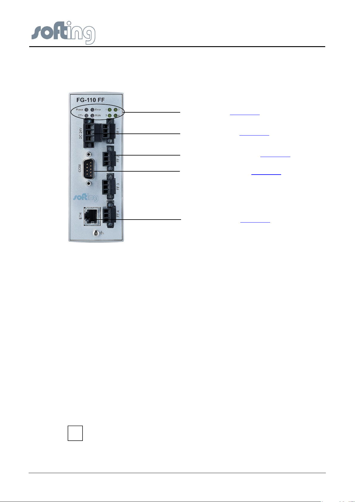
The LED may also light up if the bus has not been connected or is defective.
i
LED Block – see chapter 2.2
Power Supply – see chapter 2.3
Up to 4 H1 Segments – see chapter 2.6
Serial Port RS232 – see chapter 2.5
Ethernet Port – see chapter 2.4
2 Hardware Installation
2.1 Overview Hardware – FG-110 FF
Fig 2.1-1 Overview Hardware – FG-110 FF power and data connections
2.2 LED Block – Meaning
PWR
The "PWR" LED indicates the power supply status:
This green LED is on when the internal power supply is ensured. If this LED is off, the supply
voltage (24 V) is missing or the internal voltage generation is defective. In this case, the unit
needs to be returned to the manufacturer for repair.
LAN
The green "LAN" (Local Area Network) LED is on when proper communication (link
connection to a hub/switch/NIC) with the Ethernet is possible. It goes off temporarily during
transmission.
RUN
The "RUN" LED is available for application-specific purposes and is off by default.
ERROR
The "ERROR" LED is available for application-specific purposes and is off by default.
BUS
This green LED shows the bus activity of the FF H1 channel. The LED indicates the status
data exchange.
page 8 of 85 V1.3
Page 9
Softing Linking Device –
Manual for Configuration, Installation and Maintenance
Hardware Installation
L+
M
The starting current of the Linking Device may be up to 3A. The power supply
must provide this starting current in compliance with the voltage range to ensure a
safe start-up. Replacement Part for this connector is Phoenix Contact MSTB2,5/3STF-5,08 BK AU.
i
2.3 Power Supply
The Linking Device is powered by 24 V DC. The power supply plug connector is included in
the delivery. The power supply socket connector on the front panel is labeled DC 24V-.
Fig 2.3-1 Linking Device Power Supply
The two power supply terminals are labeled L+ and M. L+ must be connected to 24V and M
to 0V. The two terminals are provided with an internal reverse-polarity protection. The
functional ground terminal is labeled with the symbol and must be connected to the
protective ground. For use in an environment that is highly subject to electromagnetic
interference, an additional ground connection can be provided at the grounding screw below
the "LAN" connector.
Proper grounding is a prerequisite for compliance with the EMC directives and for ensuring
proper operation.
The power supply is connected to the plug connector via flexible wires with a cross section of
0.75 to 1.5 mm². The ground connection wire must have a cross section of 1.5 mm.
The Linking Device has an internal safety fuse which blows if an over voltage (of approx.
30V or higher) occurs in the power supply or if a fault occurs in the device. The safety fuse
can only be replaced by the device manufacturer.
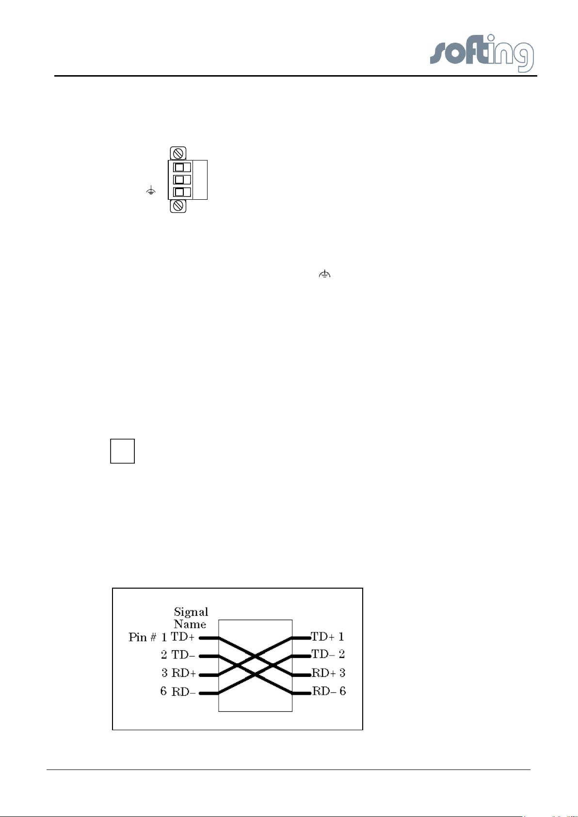
2.4 Ethernet Port
The Linking Device is equipped with one 10/100 Base-T Ethernet interface receptacle.
Connect the Linking Device to the PC that will be used for configuration, if it is possible using
an existing Ethernet Hub, Switch or Router. If you want to connect your PC to the Linking
Device directly do it with a crossover cable.
Fig 2.4-1 Crossover cable pinout
V1.31 page 9 of 85
Page 10
Softing Linking Device –
Manual for Configuration, Installation and Maintenance
Hardware Installation
Pin
MDI Signal Pinout
(Standard Ethernet Cable)
1
TD+
2
TD-
3
RD+
4
Not used
5
Not used
6
RD-
7
Not used
8
Not used
Pin #
Connector
1
Pin #
Connector 2
Signal
Description
1
1
Reserved
Do not connect
2 3 RXD
Receive Data
3 2 TXD
Transmit Data
4
4
Reserved
Do not connect
5 5 GND
Signal Ground
6
6
Reserved
Do not connect
7
7
Reserved
Do not connect
8
8
Reserved
Do not connect
9
9
Reserved
Do not connect
The Ethernet port corresponds to the standards IEEE 802.3 100BASE-TX/10BASE-T and
supports auto negotiation.
The pin assignment corresponds to MDI (Medium Dependent Interface).
Table 2.4-1 Ethernet Pins
2.5 Modbus
2.5.1 MODBUS TCP
The FG-110 FF is able to communicate with the HSE (High Speed Ethernet protocol of
Fieldbus Foundation) and Modbus TCP over the same Ethernet port.
2.5.2 MODBUS serial (RS232 / RS485)
The FG-110 FF provides a serial interface based on RS232.
The connection is made using a 9-pin male D-sub connector with the following pin layout:
Table 2.5-1 COM PIN Allocation
But mostly the units are connected to the Linking Device by the Interface RS485.
The FIM-110 FF offers a solution with a serial converter RS232 to RS485 (9185 see “Stahl
Manual”) of the company Stahl. For detailed information please follow the user guide of
page 10 of 85 V1.3
Page 11

Softing Linking Device –
Manual for Configuration, Installation and Maintenance
Hardware Installation
+
-
Stahl. You will find this manual on the CD-ROM or on the internet web page http://www.r-
stahl.com
2.6 FF H1 fieldbus connection
The fieldbus terminals are mounted in 4 sets of three terminals for the positive and negative
conductors and a shield (FF1 – FF4). Although the Linking Device is not polarity sensitive,
other components in the segment such as junction blocks may require correct polarity.
With 3-pole terminal blocks, up to 4 separate fieldbus segments can be connected. The FFH1 interfaces comply with type 114 of the FF physical layer profile, which is characterized by
● standard power signalling and voltage mode
● separately powered operation (galvanically isolated) no intrinsic safety
● the fieldbus cables +/- can be interchanged.
● wire diameter: 0.14 - 1.5 mm2, AWG 28-16
● replacement parts for the terminal block can be obtained from Phoenix-Contact
(http://www.phoenixcontact.com/) as part type MC 1,5/3-STF-3,81 BK AU.
Fig 2.6-1 Pin assignment 3-pole terminal block for FF H1 Connections
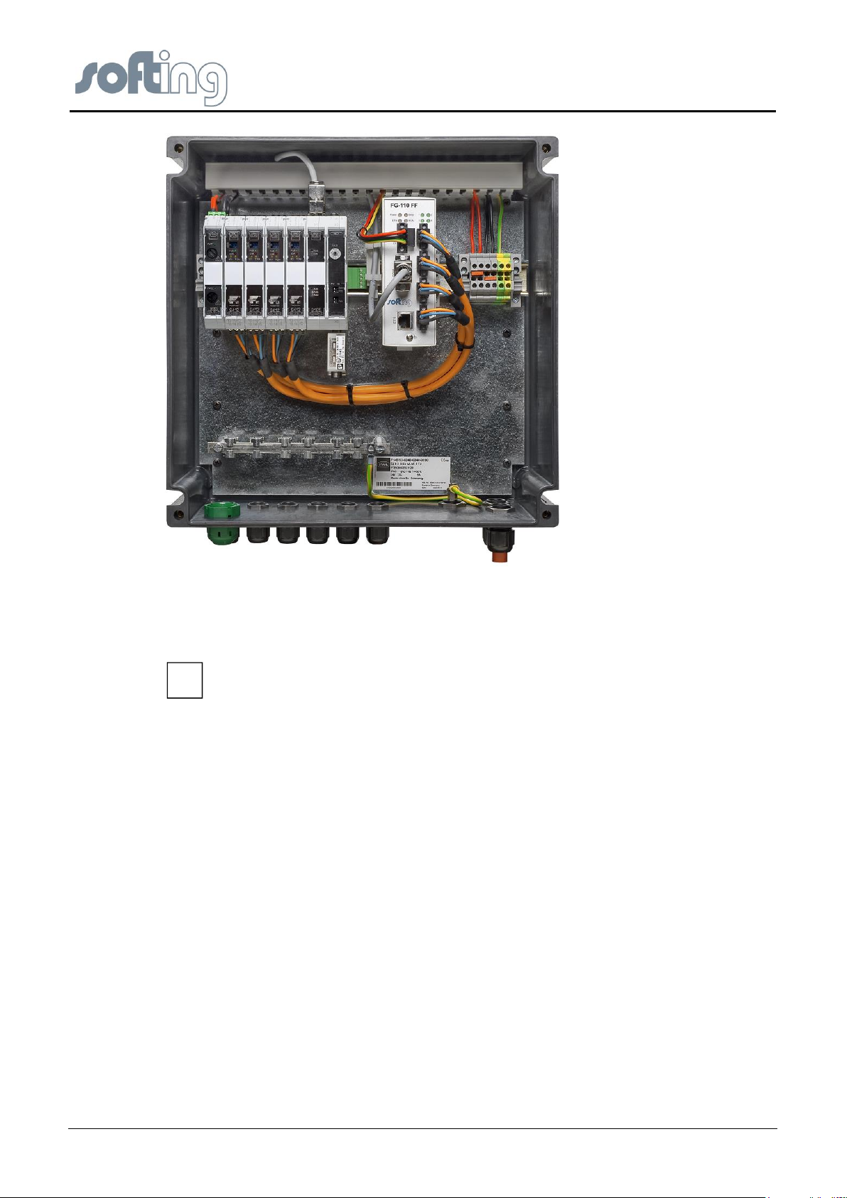
2.7 FIM-110 FF - The pre-wired Installation of the FG-110 FF
The FIM-110 FF has an IP-65 housing.
The upper cover provides access to single parts like
● the Linking Device FG-110 FF,
● the RS-232 / RS-485 converter,
● the fieldbus power conditioners/terminators,
● the power supply board and ground terminals.
The enclosure cover provides access to the terminal blocks. To open either cover of the
enclosure, use a ¼ inch blade screwdriver to remove the appropriate screw on the unhinged
side of the enclosure
The Linking Device is intended for mounting in a control cabinet. One of the favorite
possibilities is the FIM (SOFTING Foundation Fieldbus Interface Module FIM 110)
V1.31 page 11 of 85
Page 12
Softing Linking Device –
Manual for Configuration, Installation and Maintenance
Hardware Installation
Please ensure against the direct contact with the sunlight.
i
Fig 2.7-1 Mounting the Linking Device ready for use: the SOFTING Foundation Fieldbus Interface Module FIM 110
The Linking Device is convection-cooled. It therefore needs to be installed in such a way that
the ventilating ducts are at the top and bottom of the unit.
2.8 Installation Overview
The whole installation is wired as shown in the picture.
The network connectivity of the PC is part of the private Ethernet. The connectivity between
H1 Links and H1 Devices is realized by shielded twisted pair. The maximum distance
depends on the numbers of H1 Devices and other surrounding conditions, normally 1900 m.
page 12 of 85 V1.3
Page 13
Softing Linking Device –
Manual for Configuration, Installation and Maintenance
Ethernet Network Configuration
1
3.1
2
3.2
4
3 Ethernet Network Configuration
3.1 Linking Device IP address Configuration
The Linking Device is delivered with a pre-configured IP address 192.168.177.177. It must
be assigned an IP address from your LAN address range. Furthermore, subnet mask and
gateway IP address must be set.
To configure the Linking Device a private network between a PC and the Linking Device
must first be established. This can be done with a PC dedicated to the Linking Device or a
PC used for another purpose can be temporarily configured for the task. If a PC from another
network is used, carefully record the current IP address and other settings so the PC can be
returned to its original network when configuration of the Linking Device is finished. If using a
PC attached to another network, shut down the PC and remove it from the network before
proceeding to set up the Linking Device private network.
Please see the chapter <Configuration><Internet Protocol> and follow the instruction for the
IP configuration in the Linking Device.
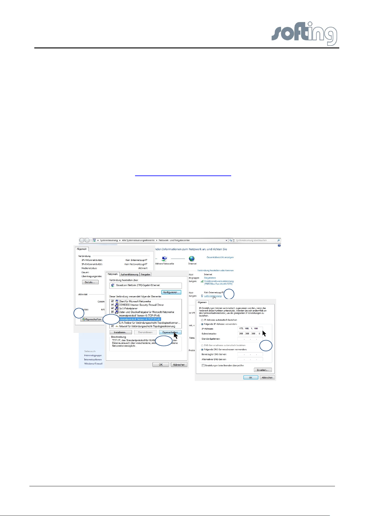
3.2 PC IP address Configuration
To install a private network on your PC please press the Microsoft Windows <Start> button
and choose <Control Panel><Network and Dial-up Connections>. The following screen
appears.
Fig 3.2-1: Configure IP address on PC
Follow the red numbered buttons. In the field IP address (4) fill in the IP address of the
subnet you have chosen. In this example we have chosen the address 192.168.1.10 as the
IP address for the PC.
Store the inputs with OK and close the window.
V1.31 page 13 of 85
Page 14

Softing Linking Device –
Manual for Configuration, Installation and Maintenance
Linking Device FG-110 FF - Internal Web Server
4 Linking Device FG-110 FF - Internal Web Server
The internal web server of the Linking Device FG-110 FF offers the possibilities to configure
the Linking Device (like IP address settings or Modbus mapping), to get diagnostic
information on the fieldbus or Modbus as well as to monitor process values of the connected
field devices.
4.1 Homepage of the Linking Device FG-110 FF
The FG-110 FF web server application is optimized for Mozilla Firefox browser but it is also
possible to use Microsoft Internet Explorer.
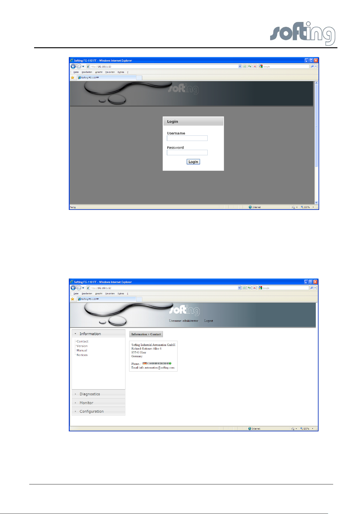
When you start the web server the first time then please use the following default IP address,
login and password.
IP address: 192.168.1.10
Password: fgadmin
Login: administrator
After login was successful, the homepage screen of the Linking Device Web Site appears.
The screen is divided into three partitions. At the top of the screen you see the headline with
the input line for the http:// addresses (browser standard).
At the bottom left you see the headers of the main menu of the Linking Device Web Site
which will be described in detail in the following text. Next to the content menu listing you see
a free partition where the content of the single main menu items will be shown.
The headers of the main menu of the Linking Device Web Site are:
● Information
● Diagnostics
● Monitor
● Configuration
The submenu associated with each active menu opens automatically.
page 14 of 85 V1.3
Page 15
Softing Linking Device –
Manual for Configuration, Installation and Maintenance
Linking Device FG-110 FF - Internal Web Server
Fig 4.1-1 Starting Screen
4.2 Information
4.2.1 <Information><Contact>
When you click on <Information><Contact> you will see the contact address of Softing
Industrial Automation GmbH on the free partition on the right of the screen. This view is the
default Homepage.
Fig 4.2-1 Contact
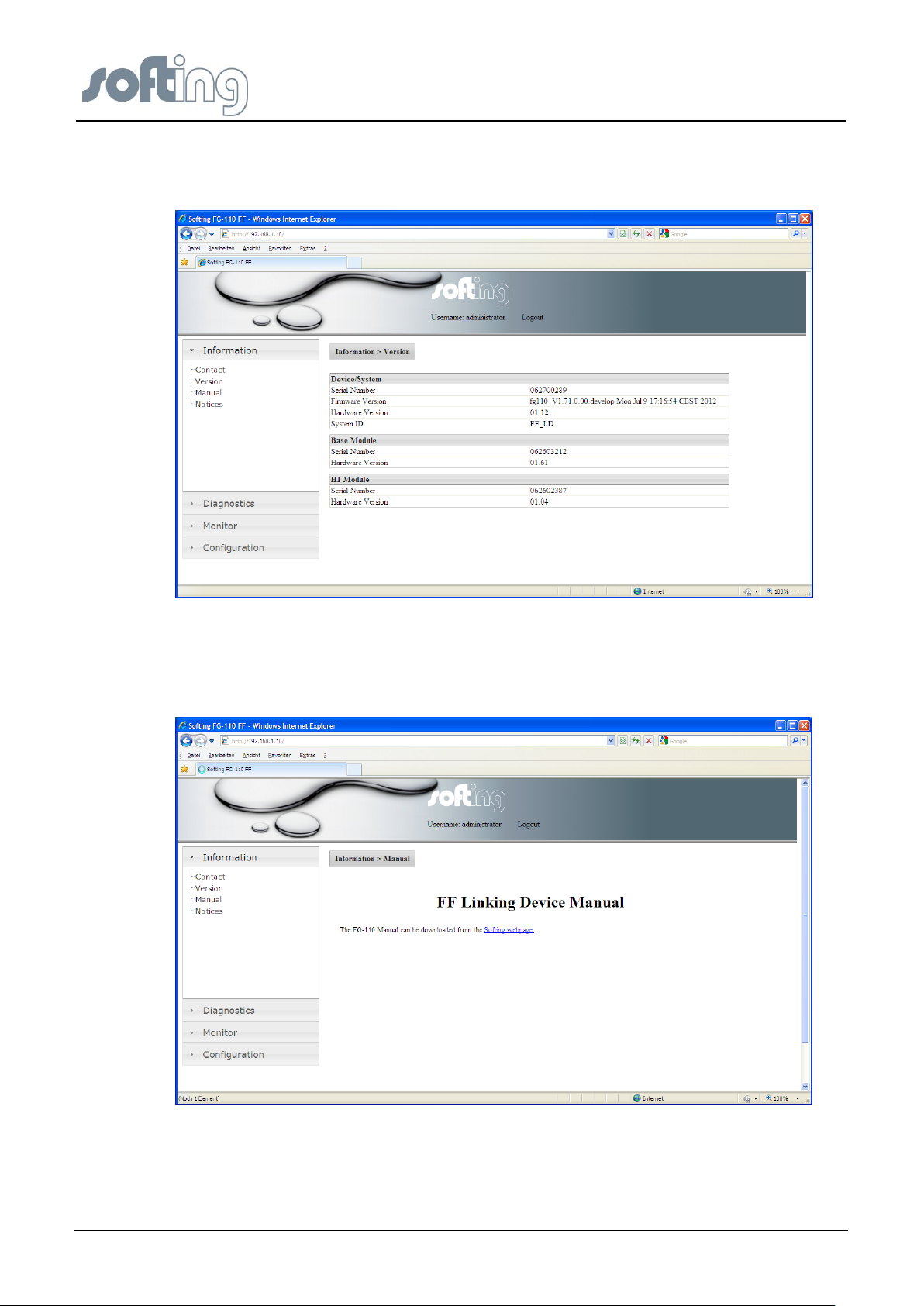
4.2.2 <Information><Version>
When you click on <Information><Version> you will see a large number of version numbers,
serial numbers and ID numbers of the connected devices in the in-house LAN on the free
V1.31 page 15 of 85
Page 16
Softing Linking Device –
Manual for Configuration, Installation and Maintenance
Linking Device FG-110 FF - Internal Web Server
right partition on the right of the screen. Here you can find the numbers of the several Linking
Device modules which are important for questions relating to the support of Softing Industrial
Automation GmbH.
Fig 4.2-2 Version
4.2.3 <Information><Manual>
Click on <Information><Manual> and you find a link to download the manual from the Softing
webpage
Fig 4.2-3 User Manual
page 16 of 85 V1.3
Page 17
Softing Linking Device –
Manual for Configuration, Installation and Maintenance
Linking Device FG-110 FF - Internal Web Server
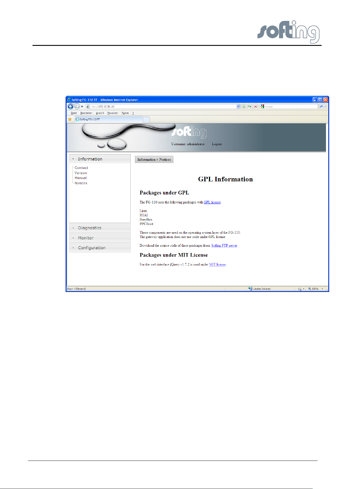
4.2.4 <Information><Notices>
Click on <Information><Notices> to obtain topical information about licenses which are used
in the Linking Device.
Fig 4.2-4 Actual information for the customer
4.3 <Diagnostics>
Under the menu item <Diagnostics> the headers <System>, <Internet Protocol>, <Fieldbus>
and <Advanced> are listed.
The tables listed under the menu item <Diagnostics> show the values in display mode.
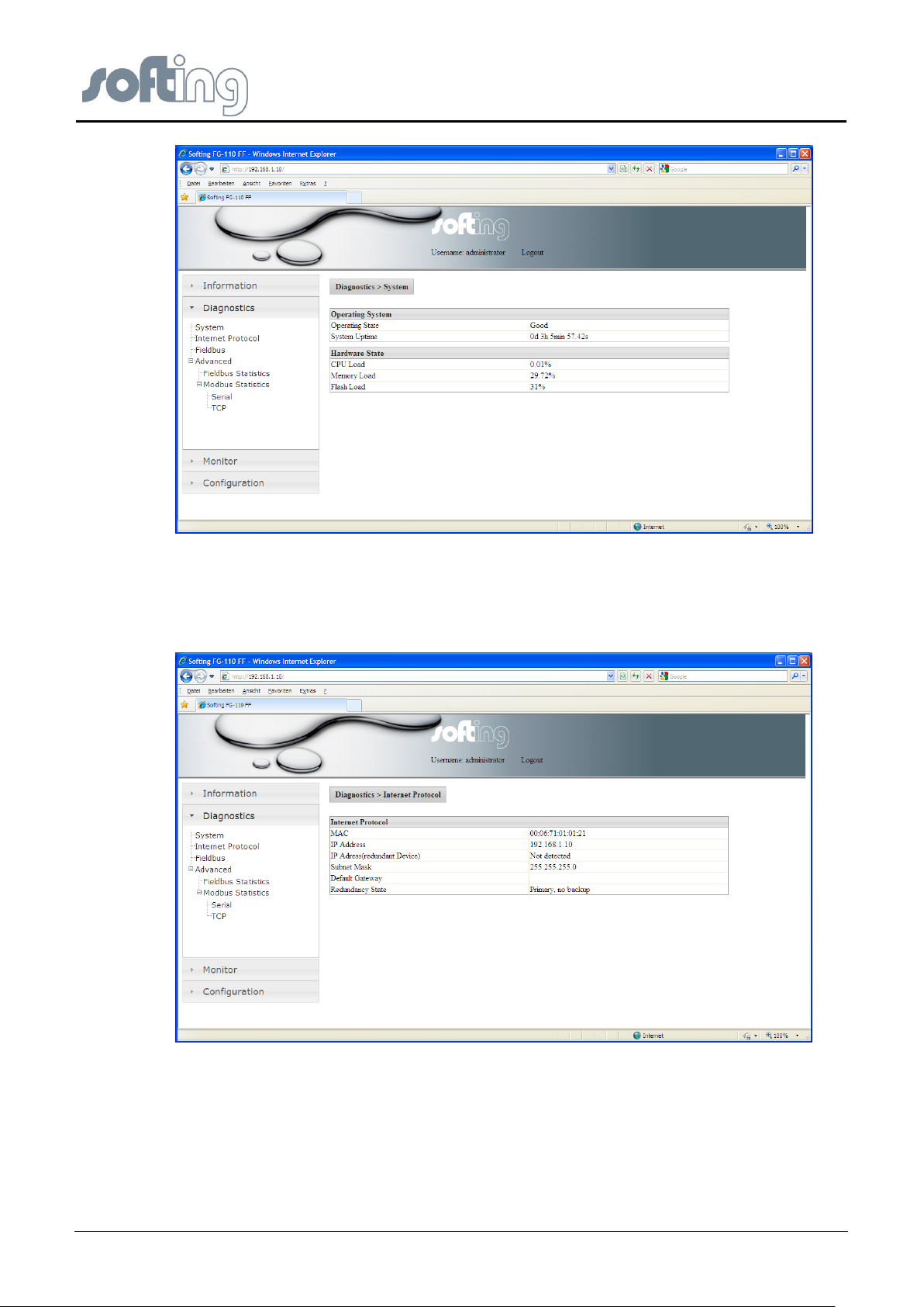
4.3.1 <Diagnostics><System>
The operating system and the application layer can be diagnosed.
The first table lists
● the Operating State,
● the System Uptime of the configured Linking Device Operating System.
The second table lists (in percent (%))
● the states of CPU Load,
● the Memory Load,
● the Flash Load of the configured Hardware.
The displayed data shows the usage rate of the system in %.
V1.31 page 17 of 85
Page 18
Softing Linking Device –
Manual for Configuration, Installation and Maintenance
Linking Device FG-110 FF - Internal Web Server
Fig 4.3-1 System - actual Information of the Linking Device state
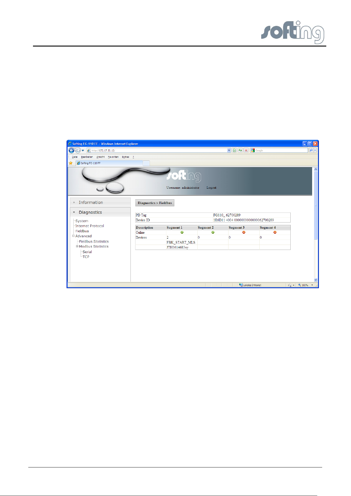
4.3.2 <Diagnostics><Internet Protocol>
The table <Internet Protocol> lists the main information the system has got about the
connected subnet.
Fig 4.3-2 Data of the Internet protocol
4.3.3 <Diagnostics><Fieldbus>
Fieldbus segment diagnostics are provided to give you a quick view of what is attached to
the Linking Device. It shows how many segments are active.
On the screen two tables are shown.
The first table shows the information about the Linking Device, the PD Tag as well as the
Device ID. The PD Tag can be modified in the Configuration page “LD Settings”.
page 18 of 85 V1.3
Page 19
Softing Linking Device –
Manual for Configuration, Installation and Maintenance
Linking Device FG-110 FF - Internal Web Server
Underneath it another table shows which segment (H1 Link) of the Linking Device (FG-110
FF) is occupied and how many FF-H1 devices are connected under each segment.
Additional, for each available FF-H1 device the tag name is shown. So, the this table provide
a simple live list of the FF-H1 network. Please note that this list will be updated just be
clicking on “Fieldbus” again.
For each Linking Device up to 4 H1 Links (segments) are available. And under each
segment H1 Link up to 16 devices H1 are possible.
(In this example: Segment 1 (H1 Link) from Linking Device HSE_ DEVICE_1 is occupied by
two connected devices (H1 Device), flagged with a green check mark. The segments 2-4
(H1 Links) are free, flagged with red buttons.
Fig 4.3-3 Shows the actual configuration – Linking Device and occupancy of the 4 H1 Links (Segments)
4.3.4 <Diagnostics><Advanced>
The menu item <Diagnostics><Advanced> therefore shows two different menu items.
● Fieldbus Statistics
● Modbus Statistics.
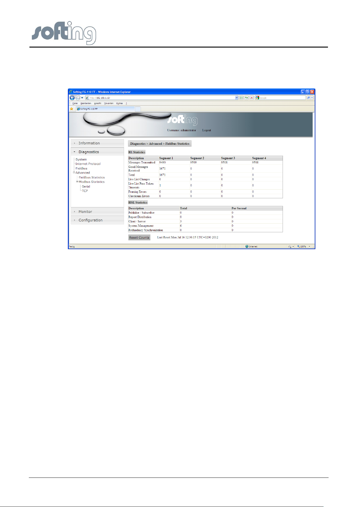
4.3.4.1 <Diagnostics><Advanced><Fieldbus Statistics>
The menu item <Fieldbus Statistics> shows two different tables. The values specified apply
to the time since the program has been started or the latest <Reset count>.
The first table shows statistical data for each single occupied segment of the H1 Device.
● Messages Transmitted:
Assumption of all the transmitted messages for each occupied segment
● Good Messages received:
Assumption of the good messages received at each occupied segment.
● Total: Number of total retries.
● Live List Changes: Number of total live list changes
● Live List Pass Token Timeouts: Number of pass token timeouts; Under good
conditions it should be “0”
V1.31 page 19 of 85
Page 20
Softing Linking Device –
Manual for Configuration, Installation and Maintenance
Linking Device FG-110 FF - Internal Web Server
● Framing Errors: Number of framing errors
● Checksum Errors: Number of checksum errors
Fig 4.3-4 Fieldbus Statistics (H1 and HSE)
The second table shows statistical data for each of the HSE Links.
● Publisher/Subscriber: Number of messages per second (average value)
● Report Distribution: Number of messages per second (average value)
● Client/Server: Number of messages per second (average value)
● System Management: Number of messages per second (average value)
● Redundancy Synchronization: Number of messages per second (average value)
Pressing the button <Reset count> sets the counter to zero. Recording of the statistical data
starts at the beginning.
You have to click<Fieldbus><Statistics> once again to see the new results.
4.3.4.2 <Diagnostics><Advanced><Modbus Statistics>
The Modbus communications statistics provide information on the data and packets received
and transmitted by the Modbus slave interface. Select <Serial> if you want to monitor the
Modbus RTU link or <TCP> if you are monitoring the Modbus TCP/IP communications.
Therefore the Modbus may work with two different protocols. Menu item
<Diagnostics><Advanced> <Modbus Statistics> shows two different menu items.
● Serial
● TCP
page 20 of 85 V1.3
Page 21

Softing Linking Device –
Manual for Configuration, Installation and Maintenance
Linking Device FG-110 FF - Internal Web Server
<Diagnostics><Advanced><Modbus Statistics><Serial>
The menu item <Serial> shows statistical data of a Modbus connected on a serial interface.
First messages and CRC errors from received data are listed. Then messages and error
responses from the transmitted data are listed. RS232 needs a converting unit
RS232/RS485 and a separate data connection between Linking Device and Modbus.
The values specified apply to the time since the program has been started or the latest
<Reset count>.
Fig 4.3-5 Modbus Serial Statistics
Pressing the button <Reset count> sets all counters to zero. Recording of the statistical data
starts at the beginning.
You have to click<Modbus Statistics> <Serial> once again to see an update of the results.
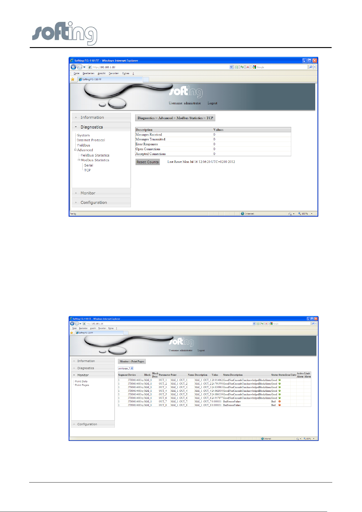
<Diagnostics><Advanced><Modbus Statistics><TCP>
The menu item <TCP> shows statistical data of a Modbus connected using TCP. First
received and transmitted messages are listed. Then the error responses are counted. Finally
open and accepted connections are listed.
Pressing the button <Reset count> sets all counters to zero. Recording of the statistical data
starts at the beginning.
You have to click<Modbus Statistics> <TCP> once again to see an update of the results.
V1.31 page 21 of 85
Page 22
Softing Linking Device –
Manual for Configuration, Installation and Maintenance
Linking Device FG-110 FF - Internal Web Server
Fig 4.3-6 Modbus TCP Statistics
4.4 <Monitor>
Click <Monitor> Options to display the point pages and point data.
4.4.1 <Monitor> <Point Pages>
Point Pages provide a means to view the Process Value (PV) or Output of a Function Block
and its status on one or more web pages. Multiple pages can be configured to fit the
application and to keep track of the different parts of the plant.
First click <Point Pages> to select the desired part of data. It may be one or more rows or
sites.
Fig 4.4-1 Statistics of the H1 Devices for the selected page
page 22 of 85 V1.3
Page 23
Softing Linking Device –
Manual for Configuration, Installation and Maintenance
Linking Device FG-110 FF - Internal Web Server
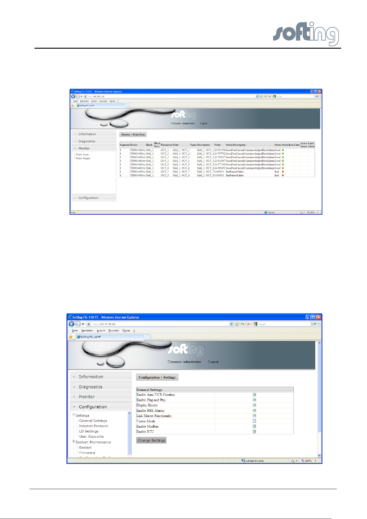
4.4.2 <Monitor><Point Data>
Next click <Point Data> to see the details of all available point pages displayed for the
selected page.
Fig 4.4-2 Monitor Point Data – all Data of your plant will be shown
4.5 <Configuration>
The menu item <Configuration> is a very important item of the Linking Device web site. Here
the user with administrator rights has the possibility to change network parameters, configure
the point pages and perform Modbus mapping.
4.5.1 <Configuration><Settings>
4.5.1.1 <Configuration><Settings><General Settings>
Fig 4.5-1 General Settings of the Linking Device
V1.31 page 23 of 85
Page 24

Softing Linking Device –
Manual for Configuration, Installation and Maintenance
Linking Device FG-110 FF - Internal Web Server
Please note that the feature “Automatic VCR creation has to be enabled when the
tool FF_CONF is to be used for the Foundation fieldbus configuration
i
1.) Enable VCR Creation
If this feature is “on” then the Linking Device establishes the VCR connection by them self.
Please read in the software manual if it is necessary or not.
Some examples
Softing Configuration Tool (FF-CONF) --> On
Emerson AMS™ Software --> On
NI-FBUS Configuration Tool --> Off
2.) Enable Plug&Play
This feature makes sure that pre-configured device can be used without a configuration tool.
3.) Display Blocks
This feature enables or disables the point page functionality. The use of the point page
creates a lot of traffic of the FF-H1 network. If you don’t use this Monitor feature then you
can save more H1 bandwidth and faster reaction time over Modbus.
4.) Enable HSE Alarms
The Linking Device is able to use the already configured alarm VCR’s in the FF-H1 devices
or can established new one.
5.) Link Master Functionality
In case of visitor mode it can make sense to disable the Link Master functionality. If no Link
Master is available then a time-out will follow after 6 sec.
6.) Visitor Mode
When the Linking Device is in visitor mode it can be connected to a running FF-H1 network
with the FF-Host system without affecting the established communication.
7.) Enable Modbus
This button enables or disables Modbus TCP and RTU.
8.) Enable Modbus RTU
Modbus RTU runs over the same serial interface (RS232) which is necessary to establish an
application with HSE device redundancy. To use redundancy together with Modbus TCP the
feature “Modbus RTU” has to be disabled.
page 24 of 85 V1.3
Page 25
Softing Linking Device –
Manual for Configuration, Installation and Maintenance
Linking Device FG-110 FF - Internal Web Server
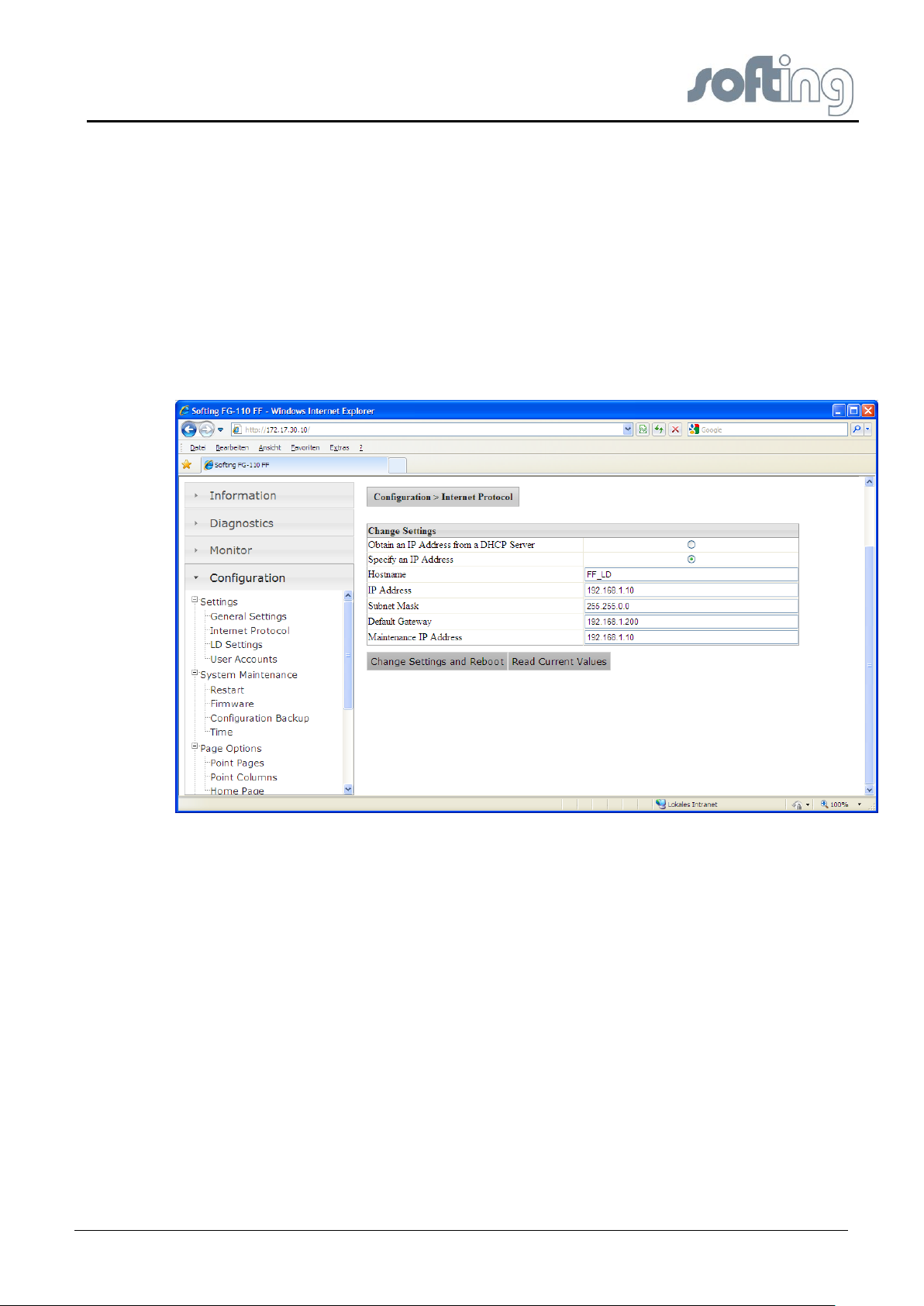
4.5.1.2 <Configuration><Settings><Internet Protocol>
The Linking Device is delivered in a default configuration. To change the default internet
protocol settings into assigned values of the chosen subnet in which the installation is
running you click <Configuration><Internet Protocol>.
A table which enables you to change settings appears.
First you can click a button to <obtain an IP address from a DHCP server>. When you click
this button the IP address is a random address chosen from the DHCP server. To find out
the IP address of the Linking Device you can use the tool “Search and Configure” (SAG.exe)
or the live list of the FF-CONF tool. Both tools are available on the CD-ROM or on the
Softing homepage.
Fig 4.5-1 Configure the Internet Protocol
To keep the systems under your control click the button <Specify an IP address>.
Underneath this button input fields become active to insert:
● Domain name: configurable name for the domain
● IP address: must be compatible with the subnet you choose for the PC setting, must
be present in any case.
● Net mask: default with 255.255.0.0, no change needed, must be present in any
case.
● Gateway: It is not necessary to configure a Default Gateway if the host and Linking
Device share the same network.
● Maintenance IP address: IP address of the connected PC in the same subnet.
The Maintenance IP Address is required to download the Linking Device firmware
from a maintenance server. The maintenance server is a TFTP server (Tiny File
Transfer Protocol) that contains an image of the flash memory content of the Linking
Device (it is also possible to download a file via the website). In that case it is not
necessary to install a maintenance server and to specify its address.
V1.31 page 25 of 85
Page 26
Softing Linking Device –
Manual for Configuration, Installation and Maintenance
Linking Device FG-110 FF - Internal Web Server
Do not access the web server of the Linking Device before the NEW
NETWORK SETTINGS or ERROR OCCURED message is displayed in
the browser window. If you do so, you will have to clear the cache of
your web browser after the boot process has finished, and then reestablish a connection to the web server of the Linking Device.
i
<Change Settings and Reboot>
When you click the button <Change Settings and Reboot> the web site shuts down and the
system reboots.
The input values will be checked for consistency. If the input values are not consistent, the
Linking Device will propose consistent values. You can use the proposed values by clicking
<yes> or keep the values you entered by selecting <no>.
The Linking Device will be rebooted after a few seconds and the new values will be
accepted.
If you change the IP address of the Linking Device, the IP connection between PC and
Linking Device will be lost. You have to use the new IP address to re-establish web access
to the Linking Device.
If all parameters are correct, the new values are accepted and displayed.
<Read Current Values>
If you changed some of the parameters and you are not sure of your changes, click the
button <Read Current Values>. Input fields which are already filled are shown again.
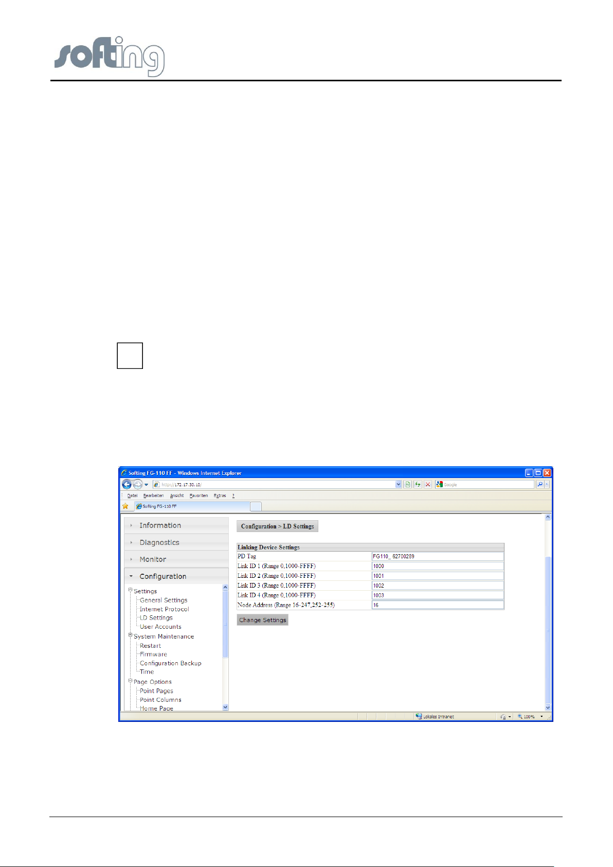
4.5.1.3 <Configuration><Settings><LD Settings>
Fig 4.5-2 Configuration of Linking Device Settings
Each Linking device gets a unique PD-Tag which includes the serial number.
The Webpage “LD-Settings” can be used to change the PD-Tag of the Linking device, the
Link ID as well as the Node Address of the H1 links.
page 26 of 85 V1.3
Page 27

Softing Linking Device –
Manual for Configuration, Installation and Maintenance
Linking Device FG-110 FF - Internal Web Server
4.5.1.4 <Configuration><Settings><User Account>
The Linking Device is shipped with default user password. Under this menu item you can
change the settings of the user passwords. Due to the jobs the user executes in this web site
there are several graduations for admission control.
The following standard logins and password are available.
Login: administrator Password: fgadmin
Login: maintenance Password: keepitgoing
Login: operator Password: runit
Login: executive Password: showme
These passwords can be configured with administrator rights.
Fig 4.5-3 Change user accounts – new Passwords
The following rights are connected to the pointed out roles:
The administrator can
● configure network settings (address, default)
● set passwords
● set time settings
● set home page options
● restart applications
in addition to all the functions of the other roles listed below.
The maintenance, executive and operator can just monitor the process values (point
pages) and the diagnostic. They have not access to all configuration sides.
V1.31 page 27 of 85
Page 28

Softing Linking Device –
Manual for Configuration, Installation and Maintenance
Linking Device FG-110 FF - Internal Web Server
You can install user passwords for four user groups. Fill in the new password and confirm
your input with a second input. The input mode is always the same for all user groups.
When you click the button <Change Password> the passwords will be changed and
activated the next time you enter the web site.
The administrator can modify any system or field device setting. Thus use caution when
changing the administrator password. If the administrator password is lost, you will not be
able to set up the Linking Device und and it is necessary for a staff member of Softing to
reset the password.
4.5.2 <Configuration><System Maintenance>
4.5.2.1 <Configuration><System Maintenance><Restart>
Restart causes the start of the program from the beginning with all settings stored last.
Fig 4.5-4 Restart of the HSE Device
Pressing the button <Restart now> causes another window to appear with the question
whether the restart of the device is desired. Seek the required file and
● Click <OK> to start the restart of the device.
Click <Cancel> to return the program to the beginning. Each setting is persistent.
4.5.2.2 <Configuration><System Maintenance><Firmware>
Clicking the button <seek> the Firmware Update page opens a file selector box to select the
firmware file to be downloaded. Click <Download Firmware and Reboot> to start the
download process. Firmware download and flash memory update take between one and two
minutes. You can observe the progress of the update process in the browser window.
During Reboot, the IP connection between PC and Linking Device will be lost.
Do not access the web server of the Linking Device before the SUCCESS message is
displayed in the browser window. If you do so, you will have to clear the cache of your web
browser after the boot process has finished, and then re-establish a connection to the web
server of the Linking Device.
The end of the boot process is indicated by a reboot of the Linking Device.
page 28 of 85 V1.3
Page 29

Softing Linking Device –
Manual for Configuration, Installation and Maintenance
Linking Device FG-110 FF - Internal Web Server
Please note that while the software download is running the connection between
the PC and the Linking Device will not be closed or the power supply of the
Linking Device disconnected. This can destroy the Linking Device.
i
Fig 4.5-5 Download Firmware and Reboot
After a new start the firmware stored in the chosen file is now valid for this configuration.
4.5.2.3 <Configuration><System Maintenance><System Backup>
Fig 4.5-6 Save your current system
V1.31 page 29 of 85
Page 30

Softing Linking Device –
Manual for Configuration, Installation and Maintenance
Linking Device FG-110 FF - Internal Web Server
Press the button <Save Configuration> another window appears on the screen which
enables you to search for a folder in your directory on your PC or external store media to
store the configuration you have created for the installation for future use.
With the button “Erase Configuration” the Linking device can be switched back to factory
default settings.
Erase causes the deletion of the valid configuration.
It is recommended that you erase the configuration part of the flash memory by checking
<Erase Configuration>. This will clear the FF configuration information (plant configuration),
but the IP configuration will not be changed.
Pressing the button <Erase Configuration> causes another window to appear with the
question whether the deletion of the configuration is desired.
● Click <OK> to start deletion of the configuration.
● Click <Cancel> returns the program to the beginning. Each setting is persistent.
If you erase the Linking Device configuration, the password will be reset to its default value.
4.5.2.4 <Configuration><System Maintenance><Time>
Click <Configuration><Time> to configure the system time.
The first table, Current Time, shows the current time on your PC, the time on the Softing
Linking Device. The difference between the current PC time and the time in the Linking
Device is shown in the field under it.
In the second table, Set Time, you can check a box Set with PC. After clicking the button
<Set Time> the current PC time and the time in the Linking Device will be synchronized and
shown in the table Current Time.
Fig 4.5-7 The possible opportunities to set time
page 30 of 85 V1.3
Page 31

Softing Linking Device –
Manual for Configuration, Installation and Maintenance
Linking Device FG-110 FF - Internal Web Server
If the Linking Device is connected to a network and if you want to use this feature, you can
select a timeserver at your facility or one near you geographically to ensure accurate time
adjustments. The device will function properly with this feature disabled but data time stamps
will be less accurate and time updates must be entered for each Linking Device. To use a
network time server, check the box <Network Time Protocol> (NTP), enter the IP address of
the time server and select the appropriate NTP packet version.
If a HSE SNTP server is configured then all other fields are greed out.
Alternately you can set the time manually. This is accomplished by checking the box
<Manual Entry>. This will enable you to enter information in the <Date> and <Time> fields.
In both cases you must confirm the input by clicking the button <Set Time>. Until then your
input will be activated.
4.5.3 <Configuration><Page Options>
Click <Configuration> <Page Options> to configure the Point Pages, the Point Columns and
the Home Page.
4.5.3.1 <Configuration><Page Options><Point Pages>
Point Pages provide a means to view the PV or Output of a Function Block and its status on
one or more web pages. Multiple pages can be configured to fit the application. Click
<Configuration> <Page Options> <Point Pages> to display the current list of Point Pages.
Fig 4.5-8 Create Pages to select information of your whole plant
With the button < >< > you can move the chosen point page so that the pages are sorted
in the order you desire.
To delete a point page which already exists, press the button <Delete> in the line of the point
page you want to erase.
To change the content of a listed point page, press the button <Edit> in the line where the
desired point page is listed.
V1.31 page 31 of 85
Page 32

Softing Linking Device –
Manual for Configuration, Installation and Maintenance
Linking Device FG-110 FF - Internal Web Server
Another window appears with a table where the valid Points for this point page are listed.
Over the table there is an input box with the name of the point page.
If you change this name you get a new point page with all the attributes of the chosen point
page.
The table below the page name has five columns. The first column is named “Point”. Under
this column, the possible Out-Blocks (AI Function Blocks) are listed. Beside the file name
you find a search field <…> for choosing another .out file from a file list.
The second column of the edit table is named “Name”. It can contain a name of the Function
Block.
The third column is named “Description”. In this field it is possible to type the description of
the Function Block.
In the next column “Up/Down” you can scroll the list. The last column “Delete” contains a
<Delete> button for each .out file in the table.
Under the table the buttons <Save Changes> and <New Point> are arranged. When you
press one of the buttons you can either save the changes of the point page or create a new
point.
Fig 4.5-9 Create a new Point or change pages
To save the changes click <Save Changes>.
To create a new Page click <New Point Page>. The input data of a new Point Page must be
treated in the same way as when existing Point Pages are changed.
After <Save Changes> and clicking <Point Pages> you see the data of all your pages again,
possibly including a new page. Without <Save Changes> the existing data remains
unmodified.
4.5.3.2 <Configuration><Page Options><Point Columns>
When you click <Configuration> <Page Options> <Point Columns> a table with various point
columns appears on the screen. A check mark in the check box right beside the point
columns enables the point columns. If the check box is empty the column is disabled and
does not appear in the point page. In this way you can build the format you need.
page 32 of 85 V1.3
Page 33

Softing Linking Device –
Manual for Configuration, Installation and Maintenance
Linking Device FG-110 FF - Internal Web Server
Fig 4.5-10 Select columns and save your selection
4.5.3.3 <Configuration><Page Options><Home Page>
When you click <Configuration><Page Options><Home Page> a table with four possibilities
for the first side of the homepage appears on the screen. You can choose between the
chapters “Information | Contact”, “Diagnostics | Fieldbus”, “Monitor | Point Monitor” or
“Monitor | Point Pages”.
Fig 4.5-11 Elect your homepage
V1.31 page 33 of 85
Page 34

Softing Linking Device –
Manual for Configuration, Installation and Maintenance
Linking Device FG-110 FF - Internal Web Server
The fields “Node” and “PD Tag” are input fields. In a connected system, the inputs
from here have an influence on the values in the FF-CONF Program. Press the
button <Set Tag> and the changed data appears as well in the FF-CONF
Program.
i
You choose the chapter for the start web side of the FG-110 FF with a click on the check box
beside the desired chapter.
When you press the button <Set Homepage> the input will be activated. The next start of the
web application will show you the selected page as your homepage. If you choose the
<Monitor><Point Monitor> you have to select the desired page. <Monitor><Point Pages>
shows you the desired page at once.
4.5.4 <Configuration><Fieldbus>
4.5.4.1 <Configuration><Fieldbus><Devices>
When you click <Configuration><Fieldbus><Devices> the table with the connected devices
to the Linking Device appears on the screen.
The table shows which segment from the Linking Device is occupied with how many devices.
The devices are indicated with their Node, their Device ID and their PD Tag.
Additionally there is information about the alarm VCR (VCR address) and the status of the
alarm (Alarm configured). When the alarm is configured ( ) then it can be used otherwise
there is a red dot ( ).
Fig 4.5-12 Change Node or PD Tag of your fieldbus devices
The fields “Segment” and “Device ID” are only display fields. No input is possible.
4.5.4.2 <Configuration><Fieldbus><Blocks>
In this site you see the blocks of all FF-H1 field devices which are connected to the Linking
Device.
Based on a possible large number of function block there are two filters:
- Segment: 1…4
page 34 of 85 V1.3
Page 35

Softing Linking Device –
Manual for Configuration, Installation and Maintenance
Linking Device FG-110 FF - Internal Web Server
- Device: Devices (PD Tags) on segment
In the table below is shown the function block type (Block Type), function block name (Block
Name) and the description.
With the “Enable” button can be selected if the bock will be displayed in Point Page Monitor
or not. By default only block with a block name are enabled.
Fig 4.5-13 Process the Block names or the Description of your Fieldbus Devices
If you designate the blocks (up to 32 ASCII-characters) it is useful – especially in large plants
– to assign self-explanatory names which say something about the location and define its
information (e.g. analog output, digital input). This facilitates control and assignment of the
displayed alerts or alarms.
4.5.4.3 <Configuration><Fieldbus><H1 Parameter>
Click <Configuration><Fieldbus><H1 Parameter> to define your parameters for the chosen
segment (H1 Link). With <Change Settings> you activate your inputs.
V1.31 page 35 of 85
Page 36

Softing Linking Device –
Manual for Configuration, Installation and Maintenance
Linking Device FG-110 FF - Internal Web Server
Please change these parameters only if you are absolutely sure it is necessary
and correct. Otherwise you will lose the Foundation fieldbus communication.
!
Fig 4.5-14 Change settings of the H1-Links
4.5.4.4 <Configuration><Fieldbus><HSE>
Click <Configuration><Fieldbus><HSE> to define your parameters for the Linking Device.
With <Change Settings> you activate your inputs.
Fig 4.5-15 Change settings of the Linking Device
page 36 of 85 V1.3
Page 37

Softing Linking Device –
Manual for Configuration, Installation and Maintenance
Linking Device FG-110 FF - Internal Web Server
4.5.5 <Configuration><Modbus>
The Linking Device allows traditional control systems access to modern fieldbus devices as
well as over the serial port RS485 and using TCP/IP. These control systems normally
include support for the Modbus communication protocol.
4.5.5.1 <Configuration><Modbus><Communication>
Click <Configuration><Modbus><Communication> to configure the Modbus Communication
settings. First check if the Modbus function is enabled and all parameters are set to a valid
value. Therefore consult the manual of your particular Modbus client and adjust the Modbus
configuration accordingly.
Most of these settings are self-explanatory and are related to configuring the serial port to
match the settings used by the Modbus Master.
If you are using Modbus TCP/IP over the Ethernet then the communication settings (baud
rate, parity, stop bits) can be ignored.
To apply the changes click <Change Settings>.
Fig 4.5-16 Change settings of the Modbus Communication
V1.31 page 37 of 85
Page 38

Softing Linking Device –
Manual for Configuration, Installation and Maintenance
Linking Device FG-110 FF - Internal Web Server
4.5.5.2 <Configuration><Modbus><Mapping>
Fig 4.5-17 Change settings of the Modbus Mapping
The functions of the Modbus mapping in the Linking Device are flexible enough to
accommodate most traditional control systems. The Modbus mapping table allows a user to
associate the output or input value of an AI or an AO Function Block with any traditional or
extended Modbus register. To add new entries click the button <New Entry>. Next type the
required Modbus register and assign the relevant process value (the out or in value of the
function block). When you have entered your entire data click the button <Change Mapping>
to apply the configuration. After a reload of the page you will see the new mapping entry.
On the FF H1 side 1 bit data length doesn’t exist. Therefore on the Modbus side the
Gateway doesn’t support Discrete Inputs and Coils.
4.5.5.3 <Configuration><Modbus><Import/Export>
To save the properties you have specified in Modbus Mapping use the function <Export>, if
you want to utilize an existing set of Modbus Mapping data use the function <Import>.
page 38 of 85 V1.3
Page 39

Softing Linking Device –
Manual for Configuration, Installation and Maintenance
Linking Device FG-110 FF - Internal Web Server
Fig 4.5-18 Import/Export of the Modbus Configuration
V1.31 page 39 of 85
Page 40

Softing Linking Device –
Manual for Configuration, Installation and Maintenance
FF-CONF Configure your plant
5 FF-CONF Configure your plant
By choosing the FF-CONFsetup.exe you will start the installation routine of the FF-CONF
program. To start FF-CONF it is not necessary to activate any network access, but without
network access online configuration is not necessary.
It is possible to create various configurations and store them in external files. FF-CONF is an
offline configuration tool and to build the Network Configuration it is not necessary to install
any fieldbus devices.
5.1 The screen FF-CONF and general descriptions
Below you see a screenshot of FF-CONF with most of the parts you will encounter while you
are working with FF-CONF. The numbers reference short explanations of the meaning and
will help you to find the particular description of the different specialist contents quickly.
5.1-1 An overview of the FF-CONF screen
The numbers on the screen will be described in the chapters 5.1.1 to 5.1.10
(1) Caption - FF-CONF, the active project, the status
(2) Main Menu – for details see chapter Main Menu
(3) Tool-Bar - Icons you can use while working. You save time using the offered functions
with one click.
(4) Main view tabs – the most important functions to build a configuration and to activate
the messaging between the blocks of the different devices.
(5) Main view, where you normally work after choosing a tab.
(6) The Trace Log shows error messages, warnings and information provided by FF-
CONF.
(7) List and properties view (items and icons) – List view icons provide a means for
handling device and block types and instances.
(8) List and properties view (contents) – show you the contents of the selected items (7) .
(9) Filtering the contents - Here you can set filters and select the contents shown in the
list view.
page 40 of 85 V1.3
Page 41

Softing Linking Device –
Manual for Configuration, Installation and Maintenance
FF-CONF Configure your plant
5.1.1 Caption
The caption shows the name FF-CONF, the file name of the active project and the program
status offline/online.
5.1.2 Main menu
In the maim menu you find the following items specially to administrate and to organize your
project. When you click on the right mouse button each of the items of the main menu allows
you to activate or deactivate the toolbar.
5.1.2.1 Project
5.1-2 Menu item Project
Here you can create a new project, open an available project, close, delete and save the
active project, rename the project (save as), save it as a template or view the properties of
the project in the right-hand part of your screen.
5.1.2.2 Edit
5.1-3 Edit
The functions of the item Edit are reserved for system-related functions.
V1.31 page 41 of 85
Page 42

Softing Linking Device –
Manual for Configuration, Installation and Maintenance
FF-CONF Configure your plant
5.1.2.3 View
5.1-4 View – shows you the displayed contents of the project
With <View> you can activate the desired contents like the Network Livelist, Schedule View
or intentionally hidden parts of the screen like Trace Log or previously activated views.
The tabs for the Network Configuration and the Function Block Application cannot be closed,
but can be brought to the foreground.
5.1.2.4 Build
The item Build consists of the two functions <Check All> und <Build All>. Both of the
functions can be done in the offline or online mode.
Fig 5.1-5 Build function
Check All
With the function <check all> the whole project is checked – network configuration as well as
function block application. This functionality can be used if you know that no download
domain can be built, for example due to missing device assignments. You see warnings and
errors in the Trace log.
page 42 of 85 V1.3
Page 43

Softing Linking Device –
Manual for Configuration, Installation and Maintenance
FF-CONF Configure your plant
Please use the download device functionality only if you are sure that the changes
will not affect other devices. Otherwise your system might not work correctly.
Inexperienced users of Foundation Fieldbus© are recommended to use
<download project>. Error messages are shown in the trace log view and will help
you to debug your control application.
!
!
Build All
<Build All> Build all first checks the configuration and then builds a download domain if there
are no error messages which prevent generation of the download domain.
A lot of information, warning and error codes are given in the Trace log. If the build all
function is done successfully you can download a device or the whole project.
5.1.2.5 Download
<Download> needs the online mode. You can download a device or the whole project.
5.1-6 Download device or project
Download Device
A single marked device can be downloaded after all the input and updates are checked for
correctness.
Download Project
All data of the project can be downloaded after all the input and updates are checked for
correctness. The download of the project transfers the download domain created by a build
from the PC to the Linking Device and the H1 Devices.
The trace log provides a lot of information. You can filter it by choosing only errors and
warnings (disable information).
After a successful download the units are fully operable.
V1.31 page 43 of 85
Page 44

Softing Linking Device –
Manual for Configuration, Installation and Maintenance
FF-CONF Configure your plant
5.1.2.6 Online
When FF-CONF is started with a new or an existent project FF-CONF is in mode offline. You
can configure devices or build your Function Block application in this mode. If you want to
see the real installation – the Network Livelist – you must change to the online mode. When
you open the livelist with <View> <Network Livelist> the program automatically changes to
online. The idea of this functionality is to change back to offline if the user does not need
online functionality. Online might need lots of performance.
5.1.2.7 Settings
The <tool settings> define the several conditions for the process which follows later,
especially storage location and data, as well as startup conditions and time cycles.
The <project settings> define information about the project like the time cycle for autosave or
the project description.
5.1-7 Tool and Project Settings
Tool Settings
5.1-8 Tool Settings – you can define a lot of properties
You define library and file locations, time cycles and enable/disable some functions.
<Project Settings>
5.1-9 Project Settings
page 44 of 85 V1.3
Page 45

Softing Linking Device –
Manual for Configuration, Installation and Maintenance
FF-CONF Configure your plant
Here you define the cycles of the auto save and the handling with Tag names. If you want to
add or to change the project description you can do it here even so the project exists.
5.1.2.8 Help
The Help function gives you information in different ways. You can call it by pressing the F1
button and you get the Help-Information for the current function you are working with. You
also can reach the Help function with the menu item Help.
Fig 5.1-10 The options of the Help function
5.1.3 ToolBar - Icons you can use while working
In this line 4 buttons are shown which can be used while FF-CONF is runing.
You can <Save Project>, start <Build All>, start <Download Project> and with the icon
<Online> you change offline/online. If you want to activate or deactivate the toolbar click the
right mouse button on any item of the main menu.
Fig 5.1-11 Activate or deactivate the ToolBar in any item of the main menu
5.1.4 Main view
Main view tabs (4) are the most important functions to build a configuration, to assign
configured devices of the <Network Configuration> with the <Network Livelist>, to configure
the <Function Block Application> and activate the messaging between the blocks of the
different devices.
Below you find a free space (5) where you normally work after you have chosen a tab.
5.1.4.1 <Network Configuration>
The tab <Network Configuration> is always unhidden. In the Network Configuration you
configure your network offline. The description of the devices must be allocated in the device
type library. Therefore see chapter Managing the Device Type Library.
To work faster you can use the offered icons:
to sort the devices, to assign and to download the project.
In the upper right corner of your working space you find two icons <Toggle drag> and
<Reset>. They allow you to relocate the devices shown in the working space and to reset to
the standard notification. First click <Toggle drag> and then to an object of the configuration.
Your mouse pointer changes to a cross and you can move the whole configuration picture
across your working space.
Fig 5.1-12 The icons <Toggle drag> and <Reset>
V1.31 page 45 of 85
Page 46

Softing Linking Device –
Manual for Configuration, Installation and Maintenance
FF-CONF Configure your plant
Fig 5.1-13 The changed mouse pointer allows you to move the whole configuration picture
5.1.4.2 <Function Block Application>
The tab <Function Block Application> is always active. Here you configure the
communication between the blocks of the H1 devices or the HSE Host. In Function Block
Application you can create different groups and applications to structure the whole plant and
its various areas.
5.1.4.3 Network Livelist
The Network Livelist shows you the currently active devices. To run your system it’s
necessary to assign configured and active devices of Network Configuration and Network
Livelist. How this is done is explained in detail in chapter Network Livelist.
In the Network Livelist you may sort the devices on PD Tags with the icon .
5.1.4.4 Parameter View
Parameter View shows you all parameters of each block as well as of the selected device as
of a block which is not associated with a device. You can change parameters if they are in
read/write mode.
5.1.4.5 Schedule View
Schedule View shows information about the cyclic behaviour of an H1 link. It lists all VCRs of
the LAS and the start time of the function blocks and their duration.
5.1.5 The Trace Log
Under the main view you see the partition for the Trace log. In the Trace log all information,
warnings and errors are listed while running the program. It shows the success of your
action. You can filter for each message type by activating the check box.
Here you see a screenshot with trace log after using the build function.
page 46 of 85 V1.3
Page 47

Softing Linking Device –
Manual for Configuration, Installation and Maintenance
FF-CONF Configure your plant
Fig 5.1-14 Example for Information and Warning in the Trace log
The source object of specific messages can be located by double clicking.
In this example the HSE Host device parameters are shown.
5.1.6 List and properties view
You choose the view to the contents of the available types of devices or blocks, the devices
or blocks or the properties of a selected field in the work space of an application (8). Under
the contents you find several icons which are different for each item to process a marked
content (7). Above you see the possibilities for filtering (9). The possibility of filtering is
different from item to item and is based on the contents.
5.1.6.1 Device Types
The device type view lists all devices in the device type library. Default device types are:
● FG 110 FF
● FG 100 FF
● FG 100 FF (Certified)
● HSE Host
The H1 Device Types have to be imported by the user.
V1.31 page 47 of 85
Page 48

Softing Linking Device –
Manual for Configuration, Installation and Maintenance
FF-CONF Configure your plant
Fig 5.1-15 Content of Device Types, the icons to process them and filters to select Device Types
Meaning of the icons below the contents:
● - to sort by Device Name
● - to import a new device,
● - to remove a marked device,
● and the count of total devices found.
5.1.6.2 Block Types
Fig 5.1-16 Content of Block Types, the icons to process them and filters to select Block Types
page 48 of 85 V1.3
Page 49

Softing Linking Device –
Manual for Configuration, Installation and Maintenance
FF-CONF Configure your plant
Meaning of the icons below the contents:
● - to sort by Manufacturer Name,
● and the count of total block types found.
5.1.6.3 Devices
Fig 5.1-17 Content of Devices, the icons to process them and filters to select Devices
Meaning of the icons below the contents:
● to sort by Manufacturer Name, Device Name, User Tag, PD Tag
● and tag list count.
V1.31 page 49 of 85
Page 50

Softing Linking Device –
Manual for Configuration, Installation and Maintenance
FF-CONF Configure your plant
5.1.6.4 Blocks
Fig 5.1-18 Content of Blocks, the icons to process them and filters to select Blocks
Meaning of the icons below the contents:
- to sort by Manufacturer Name,
- to look at FB Parameter View
● - to remove Function Block
● - to remove all unused Function Blocks
● - to copy and paste Function Blocks
The block view lists all explicitly and implicitly configured function blocks. The resource and
transducer blocks belong to the device and are not listed within the block list view.
5.1.6.5 Properties
If you choose the item properties you see the properties of any device or block that is
activated in any part of application. The properties of a selected object are displayed.
Properties View list of object types:
● Network configuration / livelist
● PC
● HSE subnet
● HSE devices (Linking Devices)
● H1 Links (Segments)
● H1 devices
● Function block application
● Group
● Application
● Block
page 50 of 85 V1.3
Page 51

Softing Linking Device –
Manual for Configuration, Installation and Maintenance
FF-CONF Configure your plant
Fig 5.1-19 The H1_Device_1 properties of the marked device are shown
5.1.7 Filtering the contents
Here you find the possibility to set filters and so you may select the contents shown in the list
view. The possibility of filtering is different from item to item and is based on the contents.
5.2 General Information
5.2.1 Floating windows
Fig 5.2-1 A special view to synchronize Network Configuration and Network Livelist in a very efficient method with
floating windows
Under the main menu item <View> <Reset Layout> the floating windows return to the default
view.
V1.31 page 51 of 85
Page 52

Softing Linking Device –
Manual for Configuration, Installation and Maintenance
FF-CONF Configure your plant
5.2.2 Objects within the Network Configuration
PC
Here you are working online or offline to build your Network Configuration and commission
your installation.
HSE Subnet
Ethernet component which corresponds with the Linking Device.
HSE Device
HSE Device or Linking Device. Field gateway to the H1 Links and the H1 devices.
H1 Link
The connective link between the HSE Device and the H1 Devices. It includes most of the
integrative functions of the field bus network. So the H1 Link object represents the port of
the linking device with the H1 VFD and the bus parameters common for every device on this
link.
H1 Device
Terminal with type information, network address, PD Tag and user tag. Details are provided
for each device in the properties view.
5.2.3 Tag Names
You find different tag names in FF-CONF. Nothing is prescribed for the User Tag. The string
specified with these tag names is unlimited.
If you see different tag names, please take into consideration that there is a difference
between user tags and FF PD tags. While user tags strings are not restricted in length and
character sets, FF PD tags are subject to the restrictions of the VisibleString data type within
FF-specs (32 ASCII characters).
As this might be inconvenient and if you don’t have any problems with the FF-restrictions,
you can enforce similarity between these tag names by selecting <Settings><Project
settings>and activate <Enforce PD tag same as User Tag>.
5.2.4 Using the buttons of the objects
Most of the objects offer the possibility to capture or to change the important data by clicking
the enclosed buttons. In the List View they allow you to build parts of the Network
Configuration. The current details are provided in the different chapters.
A double-click on the symbol of the objects of the Network Configuration or the Network
Livelist hides the units below or shows hidden units again. So you can select the units to
work with and get a better overview of this part of the installation.
page 52 of 85 V1.3
Page 53

Softing Linking Device –
Manual for Configuration, Installation and Maintenance
FF-CONF Configure your plant
Fig 5.2-2 Hide the units below with a double-click
Fig 5.2-3 Another double-click shows the hidden units
again
5.2.5 Using the context menu
Nearly all objects contain a context menu that allows you to do some of the steps to pattern
your Network Configuration or your Function Block Application. Examples are copy objects,
add and delete objects, the assign in the commissioning or set special parameters like in the
H1 Link.
Fig 5.2-4 For example the context menu of the H1 Link
5.3 Start FF-CONF
After correct installation you can start the program by clicking on
Start/Program…e.c..\Softing\FF-CONF\bin\FF-CONF.exe on your PC.
V1.31 page 53 of 85
Fig 5.3-1Start FF-CONF – Start Screen
Page 54

Softing Linking Device –
Manual for Configuration, Installation and Maintenance
FF-CONF Configure your plant
After a short time you see the screen to work with.
Fig 5.3-2 Basic screen to load an existent or a new project
The above screenshot shows the start screen of FF-CONF if you have never downloaded
device descriptions into the device library.
5.4 Managing the Device type library
HSE and H1 device types.
HSE device descriptions are preconfigured and cannot be changed. H1 device descriptions
can be added and removed. Each H1 device needs its special entry within the device type
library which must be notified before the Network Configuration can work successfully. A
device description has to be imported to the PC. You can add and delete single devices to
and from the device type library.
Before adding a device to the network configuration it has to be imported via the green
button. In the screen below you see the File selection dialog for importing a device
description.
While the .cff file is imported into the device type library possible error messages are shown
in the trace log. If there are any error messages, please contact the manufacturer of the
device for an update.
By selecting the cff-file, the information from associated .ffo and .sym files are imported as
well.
page 54 of 85 V1.3
Page 55

Softing Linking Device –
Manual for Configuration, Installation and Maintenance
FF-CONF Configure your plant
Fig 5.4-1 Select a .cff file for adding an H1 device to the list of Device Types.
The device library contains the description of H1 device types. The description of a device
(.cff-file, .ffo-file, .sym-file) is either part of the delivery of the H1 device or can be loaded
from fieldbus.org: http://www.fieldbus.org/index.php?option=com_mtree&Itemid=324
Remove a Device Type
To remove a device type from FF-CONF, select a device type within the list in the right-hand
partition of the screen (1). Click the button of the device type view (2). Acknowledge the
pop up window with <yes> (3) and the selected device type is deleted from the device type
list.
Fig 5.4-2 Remove a device type
V1.31 page 55 of 85
Page 56

Softing Linking Device –
Manual for Configuration, Installation and Maintenance
FF-CONF Configure your plant
Exception: HSE Devices cannot
be removed. You get the
notification:
!
5.5 Project handling
In the menu item <Network Configuration> you start the main configuration work of your
project.
5.5.1 Create a New Project
After the preliminaries you can start a new project.
Fig 5.5-1 Starting a new project
You choose <New> or <Open>.
New: The window (2) with the New Projects Dialog appears. Edit the project name and, if
desired, add a comment. Leave the window by pressing the <OK> button.
Open: You choose one of the shown projects to work with.
Fig 5.5-2 Open an existing project
page 56 of 85 V1.3
Page 57

Softing Linking Device –
Manual for Configuration, Installation and Maintenance
FF-CONF Configure your plant
5.5.2 Save project
You can save the project manually whenever you want. You have two options to do this:
Fig 5.5-3 Save your project manually
If you save your project at object time click the icon <save project> in the ToolBar.
Fig 5.5-4 Save your project with <save> or with <save as>
If you want to copy the project with a new name or to another folder use the function <save
as>.
In the <project settings> “autosave” you can define the auto save in any number of seconds
so that you save your project automatically after a short time of working.
Beside the autosave the project is saved on any “check”, “build” or “download”.
5.5.3 Delete Project
If you want to delete the current project you click the buttons <project> and <delete project>
in the upper left-hand corner of your screen.
Fig 5.5-5 Delete the current project
Of course you also can delete a non-current project with the functions of the operating
system.
V1.31 page 57 of 85
Page 58

Softing Linking Device –
Manual for Configuration, Installation and Maintenance
FF-CONF Configure your plant
5.6 Network configuration
The most important part of the project handling is the Network Configuration. You can
configure a network in two ways:
● You adapt the network configuration to the real existing installation,
● You configure a planned network without an existing installation and adapt it later. You
need only the offline status to do this.
Both ways have their advantages. The chosen way is to decide on your individual situation.
Of course it is possible to mix the procedure, e.g. you have some installed devices and you
configure other devices that will be installed at a later time.
5.6.1 Objects within the network configuration
The objects within the network configuration are PC, HSE subnet, HSE device, H1 Link and
the H1 Device.
5.6.2 Configure PC and Subnet
A new project already contains two preconfigured objects: a Host object representing the PC
you are working on and an HSE subnet object representing your Ethernet connection to the
HSE subnet. The configured PC and subnet with their IP addresses are shown on the screen
after starting a new project. Here you must select the valid IP addresses of the HSE subnet
in the context menu. Press the button on the HSE subnet object. A selection dialog appears
and shows the IP addresses the PC supports. The PC and the HSE device must be
configured in the same subnet area. Please ensure that you select the correct IP addresses.
Fig 5.6-1 Select an IP Address
page 58 of 85 V1.3
Page 59

Softing Linking Device –
Manual for Configuration, Installation and Maintenance
FF-CONF Configure your plant
Fig 5.6-3 Change IP Address
Fig 5.6-4 Change User Tag
5.6.3 Add a Linking Device (HSE)
To add a Linking Device to the configuration press the green button to the left of the
selected Linking Device in the list Device Types.
Fig 5.6-2 Add an HSE Device
Below the subnet field an instance of the selected device type appears on the screen.
In the field of the Linking Device you must enter the IP address which matches the real IP
5Address of the Linking Device. It also can be the IP address you want to use in your
planned configuration.
After pressing the top right-hand button in the Linking Device field you can change the IP
address. Press the button on the bottom right in the Linking Device field to change the User
Tag.
V1.31 page 59 of 85
Page 60

Softing Linking Device –
Manual for Configuration, Installation and Maintenance
FF-CONF Configure your plant
5.6.4 Add an H1 Link to a Linking Device
Next you add an H1 Link. You use the context menu to do this, using the right mouse button
to click on the HSE_Device object.
Fig 5.6-5 Add an H1 Link to the HSE Device
The H1 Link will be configured, the Port Number and the LinkID are set automatically, but in
any case you have to enter a new NodeID. If it is necessary you also can change the Port
Number and the LinkID. The port numbers are the physical ports of your linking device.
Fig 5.6-6 Change port number, LinkID or NodeID of the H1 Link
You will find an important function in the context menu of the H1 link object: <Get Min Bus
Parameters>. It optimizes the bus parameters in such a way that all the configured H1
devices on the link will be able to communicate.
Fig 5.6-7 Optimizing the bus parameters with <Get Min Bus Parameters>
page 60 of 85 V1.3
Page 61

Softing Linking Device –
Manual for Configuration, Installation and Maintenance
FF-CONF Configure your plant
The H1 link object represents the port of the linking device with the H1 VFD
and the bus parameters common for every device on this link.
You need no installed instances to configure the devices or to define block
parameters in your network configuration
i
i
5.6.5 Add H1 Device (Field Device) to an H1 Link
First you mark the H1 Link to which you want to add an H1 device. Next you select an H1
Device from your list of Device Types and add it to your configuration with a click on the
green star in the upper left-hand corner of the device type object. The chosen H1 Device is
added to your configuration.
If no H1 link exists, it is automatically created by adding an H1 Device.
Fig 5.6-8 Add an H1 device
If you want to see the parameter view of the device, click the button on the upper right-hand
corner of the H1 device object and the menu item “Device H1 Device X (device number)
Parameter” appears and shows you the parameters of the first block of the device.
Fig 5.6-9 Open parameter view
Now you can see it and if necessary you can change the configured values and write actual
values, but only if they are read/write parameters. You can do it block by block.
V1.31 page 61 of 85
Page 62

Softing Linking Device –
Manual for Configuration, Installation and Maintenance
FF-CONF Configure your plant
5.7 Network Livelist
The commissioning of your plant needs to adapt the data of your Network Configuration to
the installation which really exists (Network Livelist). You must perform the next steps to do
this.
5.7.1 Set the online status
Fig 5.7-1 The two options to go online
When you start the program FF-CONF the function <online> is not active. The Network
Livelist is not shown. The condition to show the Network Livelist is being in the online status.
In the options displayed above you can switch to the online status. Opening the network
livelist via menu <View><Network Livelist> automatically activates the online status.
5.7.2 Display the Network Livelist
The menu item <Network Livelist> shows active devices of your Foundation Fieldbus
network. You can compare the planned project and the physical devices by comparing
<Network Configuration> view and <Network Livelist> view.
Fig 5.7-2 Your first look at the Network Livelist
page 62 of 85 V1.3
Page 63

Softing Linking Device –
Manual for Configuration, Installation and Maintenance
FF-CONF Configure your plant
When you first change from <Network Configuration> to the <Network Livelist> you click on
the menu item <View> <Network Livelist>. Beside the menu items <Network Configuration>
and <Function Block application> the new menu item <Network Livelist> appears and is
active. Dependent on the size of the network, FF-CONF needs some time to update the
livelist. If you change the view to work with another part of FF-CONF the livelist works in the
background.
If you don’t see any devices which are physically available, please check
● physical connection and
● IP address range
Fig 5.7-3 The complete View “Network Livelist” – it shows you the devices which are really installed.
In the basic state of FF-CONF you can see either the Network Configuration view or the
Network Livelist view. If you want to see both pictures together use the function of
floating/docking windows. It is convenient to use a floating network livelist view to compare
configured and physical devices.
Fig 5.7-4 Pull down the Network Livelist
V1.31 page 63 of 85
Page 64

Softing Linking Device –
Manual for Configuration, Installation and Maintenance
FF-CONF Configure your plant
In the same way you can pull down the tab Network configuration. So you get two windows
in variable size and positions. This way you have the best possibilities to compare and
commission your project. You’ll see it below in the screenshot.
Fig 5.7-5 Two variable windows to compare and adapt the Network Configuration and the Network Livelist
Fig 5.7-6 Reset of the Layout
To establish the connection between a configured device and one which exists physically,
select the physical device within the live list. You have to assign the Linking Device and H1
Link first, then the H1 devices. To establish the connection between a configured device and
one which exists physically, select the physical device within the live list.
You have to assign the Linking Device and H1 Link first, then the H1 devices.
If you see different tag names, please take into consideration that there is a difference
between user tags and FF PD tags. Therefore refer to chapter Tag Names.
page 64 of 85 V1.3
Page 65

Softing Linking Device –
Manual for Configuration, Installation and Maintenance
FF-CONF Configure your plant
The communication does not take place when configured, but after loading the
project to the device.
The cycle time has to fit the macro cycle time defined on the H1 link
i
!
Device assignment is a time consuming action. During assignment, the device within the
network configuration view gets a yellow bullet. The physical device within Network Livelist
disappears if the PD tag and/or the node address have changed. As soon as the assignment
is accomplished, the physical device is displayed again and the bullet on the configured
device turns green.
A prerequisite for building and downloading code is that the configured device matches the
physical device displayed in the livelist. Necessary adaptions to the configuration can be
done both in <Network Configuration> and in <Network Livelist>, depending on your
individual requirements.
If you change the user tag or the NodeID of an H1 device in the Livelist, the H1 device uses
for a short time one of the reserved numbers 248 to 251 and also vanishes and reappears.
After about a minute the H1 device appears with its new user tag and/or its new NodeID. If
your attempt is not successful try it again.
5.8 Function Block Application
The Function Block Application defines the communication between input and output
parameters of function blocks. Depending on the installation’s topology direct communication
between the H1 Devices will be configured. If necessary the signal is republished by the
linking device(s). The blocks are defined by the imported .cff files.
Function block applications can be organized in groups and applications. A project contains
one or more groups. A group contains one or more applications. By default a DefaultGroup
and a DefaultApplication are created. The data can be shown by selecting the block in the
block view as well as clicking on the desired block in the Function Block application.
There are two ways to connect blocks in the Function Block application:
● To use a block instance of a configured device,
● to instantiate a block type.
5.8.1 New groups and applications (beside the Default Group and Application)
To simplify the overview in big installations or in the case of different requirements it is useful
to create more than one group or application.
With the icons above you can create new groups and applications, delete or copy and paste
applications. The applications names can be given individually and different cycle times can
be defined.
V1.31 page 65 of 85
Page 66

Softing Linking Device –
Manual for Configuration, Installation and Maintenance
FF-CONF Configure your plant
Each block can be used in only one application
i
Copy and paste groups and applications
To realize big installation without any problem, and to record all the blocks and connections
repeatedly use the possibility to copy and paste groups and applications.
Table 5.8-1 Copy and paste groups and applications
If you copy and paste a group or an application you copy all blocks and all the connections
but there is no association of the blocks to a device. The association to destined devices
might be established during commissioning.
5.8.2 Configure the Function Block application
There are 2 ways to configure a function block application:
● Use the devices first approach, i.e. use the function blocks of configured devices.
● Use the function block application first approach and later associate to a device. First
choose the blocks.
5.8.2.1 Devices first approach
● Configure network configuration view
● Change to Function Block application
You first configure the devices and use the Function Blocks on the devices for your Function
Block application.
Fig 5.8-1 The steps to choose the desired blocks
page 66 of 85 V1.3
Page 67

Softing Linking Device –
Manual for Configuration, Installation and Maintenance
FF-CONF Configure your plant
● Select the Function Block application tab.
● Select the blocks tab. The blocks tab contains all configured blocks. These can be
filtered.
● Set the profiles filter, for example to AI. All AI blocks are displayed in the list
● Set the selected devices filter to see the AI for a specific device.
● Add the Function Block, for example AI_5 to the Function Block application.
● Add all other blocks you need.
The screenshot shows you an example of chosen blocks and the data flow between the
blocks.
Fig 5.8-2 Chosen blocks and the flow of data between blocks and devices
5.8.2.2 Change tag names
Fig 5.8-3 Adjust tag names - you can adjust the tag names by selecting a list of function blocks within one function
block application or by selecting within the block list.
V1.31 page 67 of 85
Page 68

Softing Linking Device –
Manual for Configuration, Installation and Maintenance
FF-CONF Configure your plant
5.8.2.3 Configure connections
Fig 5.8-4 Configure connections
Configure a connection by pressing the link buttons:
1. select output pin (H1_Device _3_PID_3.BKCAL_OUT)
2. select input pin (H1_Device _3_PID_3.FF_VAL)
3. click <connect> button
Configure your application block by block. You cannot reuse a block which has already been
used.
In each application the flow of information between the blocks will be defined (e. g. Discrete
Input, Analog Output). It is not possible to control the plausibility of the joined blocks
automatically because of the high number of individual applications. Only connections which
are technologically impossible in the system will be rejected by an error message in the trace
log or marked with a red arrow (e. g. type mismatch).
5.8.2.4 Configure parameters
To switch to the parameter view, select a block and pick the parameter view using the right
mouse button.
page 68 of 85 V1.3
Page 69

Softing Linking Device –
Manual for Configuration, Installation and Maintenance
FF-CONF Configure your plant
Fig 5.8-5 Click FB Parameter View
Next you see the block parameters and can changes the values.
Fig 5.8-6 Change values of the block parameters
First select the parameter to change within the grid. Please look at the column “Handling” for
the information on whether the parameter is read/write or read only. Read only parameters
cannot be changed and therefore no edit field is displayed.
Then edit the value within the edit field “parameter value” at the bottom of the view or select
from the combo box. The parameters marked yellow are different to the default values.
To finish the configuration, press set and save the project.
5.8.2.5 Change Block Tags
You can change the block tags to get a better overview of where the block is situated, what
its special function is and so on. For the valid character set please see the chapter on
V1.31 page 69 of 85
Page 70

Softing Linking Device –
Manual for Configuration, Installation and Maintenance
FF-CONF Configure your plant
general information. Independently from the block tag the type of the block is shown in
brackets.
Fig 5.8-7 Rename blocks
Fig 5.8-8 Choose a block to see or edit parameters
page 70 of 85 V1.3
Page 71

Softing Linking Device –
Manual for Configuration, Installation and Maintenance
FF-CONF Configure your plant
If there is an error message displayed in the trace log view, this might be due to
the fact that the device is in AUTO mode and some of the parameters can only
be written in MANUAL or OOS (out of service). If this is the case, first set the
block to the desired mode by writing MODE_BLK.TARGET.
!
5.8.2.6 Changing parameters online
It is also possible to call the parameter view of all blocks of a device by selecting the device
and pressing the icon <Open parameters view> in the upper right-hand corner of the device.
Fig 5.8-9 Changing parameters online by pressing the block icon in the upper right-hand corner of the device
Now you see all the parameters of the first block (it’s the same view and processing as
explained in Function Block application). If you need to see the parameters of another block,
click the button <Block> near the top center of the displayed window. Now click the desired
parameter and you see the window Parameter Value. Choose one or more of the required
values and click the button <Set> to activate your selection.
V1.31 page 71 of 85
Page 72

Softing Linking Device –
Manual for Configuration, Installation and Maintenance
FF-CONF Configure your plant
5.8.2.7 Block types first approach
You can also enter the instance of a block type without device association to a function block
application by clicking the *button of a selected block type.
Fig 5.8-10 Add a block type
Now you can configure your function block application as described above and then
associate the blocks to the blocks of the device via the associate button. When you
associate a block, both the block tag and the configured parameters from the function block
application are used to configure the specific block on the configured device. The device tag
of the device is then listed within the function block application.
Fig 5.8-11 Associate a Function Block
page 72 of 85 V1.3
Page 73

Softing Linking Device –
Manual for Configuration, Installation and Maintenance
FF-CONF Configure your plant
The same situation appears after copying a function block application or a whole group of
function block applications because this copy action removes the device association.
5.8.3 Schedule View
The schedule view gives you an overview of the start time and duration of function blocks
and VCRs within the macro cycle for one H1 Link.
5.9 Handling Host devices
Part of an installation may be a Host device. The Host device is a customer specific system
(controller) and is a participant on the HSE subnet. It needs its own valid IP address.
Communication between the Host device and H1 devices can be configured via Host
function blocks. For details please contact Softing.
V1.31 page 73 of 85
Page 74

Softing Linking Device –
Manual for Configuration, Installation and Maintenance
Error handling and troubleshooting
Symptom
Cause
Recommended Actions
PC does not
communicate
with the Linking
Device
• Check to see if you are using a crossover cable
• Use the PING command described in
configuration to verify the IP address
and the FIM name
• Check that the browser has the proxy
server turned off
• Check that the IP address of the PC is
set as indicated in Chapter 5
Fieldbus device is
not detected
• Check your installation for correct wiring
and grounding and that a field
terminator is installed at each end of
the segment.
Device does not
show up on
segment
Unknown
No power to device
Recycle power to device
1. Ensure the device is connected to the
segment.
2. Check voltage at terminals. There
should be 9–32Vdc.
3. Check to ensure the device is drawing
current. There should be
approximately 17 mA.
Device does not stay
on segment
Incorrect signal levels.
Refer to host
documentation for
procedure.
Excess noise on
segment.
Refer to host
documentation for
procedure.
Electronics failing
Other
Check for two terminators.
Excess cable length.
Bad Power supply or conditioner
Check for incorrect grounding.
Check for correct shielded wire.
Tighten wire connections.
Check for corrosion or moisture on
terminals.
Check for Bad power supply.
Tighten electronics board.
Replace electronics.
Check for water in the terminal housing.
Can't log in to
Linking Device
Web Site
Forgot username or
password
Softing must reset passwords.
Contact Softing Support.
Can't find a specific
page or
functionality
Using an older version
of Firmware
Purchase and install updated Firmware
6 Error handling and troubleshooting
It’s not possible to describe all the different options for critical handling. Consequently the
most problems which occur most frequently in your process are described here.
If you can’t find the answer you seek please contact our service centre. The staff there will
be pleased to help you and have most experience in handling FF-CONF and the installations
around it.
page 74 of 85 V1.3
Page 75

Softing Linking Device –
Manual for Configuration, Installation and Maintenance
Error handling and troubleshooting
Symptom
Cause
Recommended Actions
Can see fieldbus
device, but can't
see the fieldbus
blocks
Device not
commissioned
Wait for device to auto commission or
enable commissioning and cycle
power on device
Can't expand any
function blocks
DD not installed
Install DD
Can't expand any
function blocks
Block not enabled
Enable block from block list
Can see some
fieldbus blocks,
but not all
fieldbus blocks
User does not have
sufficient privileges
Use higher level login and password
Returned Value
Action
OUT.STATUS is Bad:: OutOfService
Verify that the MODE.TARGET of the
block in question is in Auto.
• Verify that the MODE.TARGET of the
transducer block or function block that
is connected to the block in question
is in Auto.
• Verify that the MODE.TARGET of the
resource block of the device
containing the block is set to Auto.
• Go to Setup>Fieldbus>Blocks to
schedule the Block
MODE.ACTUAL=OOS,
MODE.TARGET=AUTO, and
BLOCK_ERR=Power_up
The block is not scheduled.
• The FF-CONF will schedule AI and MAI
blocks automatically but will not
schedule other blocks.
• Go to Setup>Fieldbus>Blocks to
schedule the Block
Error Dialog on Parameter Write
Most parameters require the block to be
placed in OOS
for the write to be accepted:
• Edit the MODE.TARGET to OOS
• Wait for the MODE.ACTUAL to
transition to OOS
Make desired parameter change:
• Edit the MODE.TARGET to Auto
• Wait for the MODE.ACTUAL to
transition to Auto
Parameter change is complete.
OUT.STATUS=Bad::ConfigurationError
For AI/MAI blocks:
• LTYPE must be set correctly for the
application
• CHANNEL must be set to a valid
transducer channel
• XD_SCALE and OUT_SCALE must
have valid UNITS and EU_0 and
EU_100 values for the application
For transducer blocks:
• Sensor configuration must be valid
V1.31 page 75 of 85
Page 76

Softing Linking Device –
Manual for Configuration, Installation and Maintenance
Appendix A - Bus Parameter Configuration
Parameter
Description
Range/
Restriction
Default value
T1
This is the preset value for the SM service timeout timer
in 1/32 of a millisecond ticks. It defines the time which
the SM kernel of the host will wait for a response to an
SM request to the field device. If the timer expires the
service will be aborted with a negative response. Its
purpose is to ensure that devices responding to system
management requests have sufficient time to carry out
necessary actions and transmit a response. For a
description of the relationship between the three timers
refer to T3.
-
480000 (15s)
T2
This is the preset value for the SM set address
sequence timer in 1/32 of a millisecond ticks. The timer
T2 is a sequence duration timer. Its purpose is to
guarantee that incorrectly executed or incomplete
sequences are aborted in the System Management
Kernel of the device. For a description of the
relationship between the three timers refer to T3.
T2 >= T3 +
3*T1 (host)
2880000 (90s)
T3
This is the preset value for the set address wait timer in
1/32 of a millisecond ticks. This time is used by the SM
kernel of the host after a new address was assigned to
a field device to wait before checking for the field device
at the new node address. The relationship between the
three timers T1, T2 and T3 is important for the host and
the device to set the address of a field device correctly.
T1 and T3 will be used on the host side, T2 within the
field device. If the value for T2 is too small a new
address cannot be assigned to the field device because
the timeout is too small. T2 should always be >= T3 +
3*T1 of the host.
-
1440000 (45s)
SlotTime
V(ST)
Device capability for how fast the device can reply upon
receipt of a PDU. This capability is measured in
MaxResponseDelay SlotTimes, V(MRD) × V(ST). Both
parameters are specified in octet durations. The
attributes SlotTime and MaxResponseDelay should be
set such that the device represents the maximum
response delay in octets of the device. The capability
can be obtained from the devices CFF file. When
configuring an H1 Link the maximum value of the
product SlotTime × MaxResponseDelay of all devices
residing on that link should be the minimum value for
the Link configuration. This is to assure that all devices
participate on the bus.
1 - 4095
8. Support for a
value less than
the default is
recommended.
MaxRespon
seDelay
Device capability for how fast the device can reply upon
receipt of a PDU. This capability is measured in
1 - 11
10. Support for
a value less
7 Appendix A - Bus Parameter Configuration
This section will help you configure the bus parameters of an H1 device or H1 link of a
linking device correctly. It gives hints and ranges for the individual parameters.
7.1 Bus parameters relevant for H1 devices
page 76 of 85 V1.3
Page 77

Softing Linking Device –
Manual for Configuration, Installation and Maintenance
Appendix A - Bus Parameter Configuration
V(MRD)
MaxResponseDelay SlotTimes, V(MRD) × V(ST). Both
parameters are specified in octet durations. The
attributes MaxResponseDelay and SlotTime should be
set such that the device represents the maximum
response delay in octets of the device. The capability
can be obtained from the device’s CFF file. When
configuring an H1 Link the maximum value of the
product SlotTime × MaxResponseDelay of all devices
residing on that link should be the minimum value for
the Link configuration. This is to assure that all devices
participate on the bus.
than the default
is
recommended.
MinInterPD
UDelay
This parameter specifies the minimum interval between
two frames on the H1 link. The minimum value of
MinInterPDUDelay which a device is able to support is
described in the CFF file of a device. When configuring
the H1 link the minimum value that can be used for
MinInterPDUDelay is the maximum of the values from
the CFF files of the used devices.
Max. value of
the capabilities
of the H1 link
and all H1
devices on the
link shall be
configured.
MaxSchedul
ingOverhea
d V(MSO)
This parameter specifies the maximum scheduling
overhead permitted an LAS DLE by the existing link
schedule. The parameters unit is the transmission
duration of one octet. This overhead is included in the
time allocated for each scheduled activity, and so is
used only during schedule construction and
determination of whether a DLE can serve as LAS for
an existing schedule. An H1 device capable value of
V(MSO) will be checked with the configured value in the
LAS domain during download of the domain.
0 - 63
63.
Max. value of
the capabilities
of the H1 link
and all BLM
capable H1
devices on the
link shall be
configured.
PreambleEx
tension
Each frame on the H1 link starts with a preamble octet
which is used by the receiving nodes (Devices) to
synchronize to the signal clock. The number of
preamble(s) can be extended when setting this
parameter. The default value is 0. Networks including
digital repeaters may require larger values.
0 - 7
0
PerDlpduPh
lOverhead
The parameter defines the physical layer induced delay
between the end of the last octet of one data link frame
as it appears on the link, and the beginning of the first
octet of any other data link frame as it appears on the
link.
2 - 63
2
Parameter
Description
Range/
Restriction
Default
value
DefTokenH
oldTime
Determines how long a device can hold a token, i.e.
how much time the device can use for acyclic bus traffic
(Client/Server connections, SM services and
alarms/events.
276 - 65000
276
DefMinToke
nDelegTime
As the accuracy of the LAS schedule has the highest
priority, the remaining time for granting the token might
be less than DefTokenHoldTime. In this case the token
2 - 32767
80
7.2 Bus parameters relevant for H1 Links
The following bus parameters are additionally relevant for configuration of H1 Links or a Link
master device.
V1.31 page 77 of 85
Page 78

Softing Linking Device –
Manual for Configuration, Installation and Maintenance
Appendix A - Bus Parameter Configuration
can be granted only when the remaining time is higher
than DefMinTokenDelegTime. The parameter is
specified in octet durations.
TargetToke
nRotTime
This parameter specifies the target time in which all
devices have been given the token for acyclic data
transfer. If the actual token rotation time is higher than
the configured value for TargetTokenRotTime the LAS
will increase the token priority. So a value of
TargetTokenRotTime that is too small could mean that
no client/server or SM service can be transmitted as
these are using the lowest priority.
1 - 60000
60000
LinkMaintTo
kHoldTime
This parameter specifies the time that the LAS uses
within a token rotation for link maintenance which is
probing for new node addresses and sending LAS
status frames.
292 - 65000
336
TimeDistrib
utionPeriod
Time Distribution PDU's will be sent on the bus in 95%
or less of that time period. The parameter is specified in
milliseconds.
10 - 55000
5000
MaximumIn
activityToCl
aimLasDela
y
This parameter specifies the internal delay time a Link
Master device needs from the detection of the failure of
a LAS to the time the Link Master sends a ClaimLAS
request. When configuring the link the minimum value
for this parameter is determined by the highest value of
all Link Master devices in the link.
1 - 4095
100
LasDatabas
eStatusSpd
uDistribution
Period
The LAS Live list database of the link will be distributed
in that time period to other LAS or link master devices
on the link. The parameter is specified in milliseconds.
A value of 1000 - 5000 is recommendable.
100 - 55000
5000
TimeSyncCl
ass
This parameter defines the quality of the clock accuracy
of a device. Thus it also defines the periods for time
synchronization because a device with a more
inaccurate clock should be synchronized more often.
The maximum value a device is capable of supporting
is described in the device's CFF file. When configuring
a link, the maximum value should be set according to
the minimum value of the used devices.
5
FirstUnpolle
dNodeId
(FUN)
The node address of the first node that will not be
polled by the LAS of the link.
FUN >= 20
AND
FUN + NUN - 1
<= 247.
248
NumConsec
UnpolledNo
deId (NUN)
Range of consecutive node addresses that are not
polled by the LAS of the link.
FUN >= 20
AND
FUN + NUN - 1
<= 247.
0
Ranges and/or restrictions denoted with the column Range/Restriction above will
be checked by the FF-CONF and an appropriate error message will be issued if
the range/restriction is violated.
i
page 78 of 85 V1.3
Page 79

Softing Linking Device –
Manual for Configuration, Installation and Maintenance
Glossary
Term
Definitions
Comment,
other term
softing Linking Device
Gateway between PC/LAN,
Modbus/LAN, Modbus serial and H1
Devices
HSE, Linking
Device
Linking Device
Gateway between PC/LAN,
Modbus/LAN, Modbus serial and H1
Devices
(softing) Linking
Device, HSE
HSE
Gateway and communication controller
between PC/LAN, Modbus/LAN,
Modbus serial and over the H1 Links
with the H1 Devices
(softing) Linking
Device
H1 Device
Terminal to record and communicate
measurements complying with the
fieldbus standards
H1 Link
Connected to the linking device.
Supplies up to 16 H1 devices with
power and data.
sometimes also
called “segment“
Network Configuration
The part of FF-CONF that allows you to
configure your plant offline.
Function Block
application
The part of FF-CONF where you build
your communication network between
the different blocks of your H1 Devices.
Network Livelist
Image of the existing installation: PC,
Network Card, Linking Devices, H1
Links, H1 Devices and Host devices
Modbus
A unit to communicate with the Linking
Device and to control the activities of
the H1 Devices. It is always a special
system and it has to prove whether it
works in combination with the Linking
Device.
The Modbus may exist as an Ethernet
version, then it is participant in the LAN.
Application In most cases works with
the serial interface RS485 and has to
be connected with the Linking Device
over an interface converter RS232 –
RS485.
8 Glossary
Explains specialist terms of the organisation, configuration, device types and the handling of
FF-CONF.
8.1 General remarks of the user manual
V1.31 page 79 of 85
Page 80

Softing Linking Device –
Manual for Configuration, Installation and Maintenance
Glossary
Term
Definitions
DHCP
Dynamic Host Configuration Protocol: Used to
configure the network parameters automatically. This
device contains a DHCP Client to retrieve the network
configuration parameters from a DHCP server on the
network.
NTP/SNTP
Network or Simple Network Time Protocol: Used to set
the system time. This device contains an NTP client for
keeping the system time synchronized with a network
time server.
Domain Name
A unique designator on the internet composed of
symbols separated by dots such as: this.domain.com
FTP
File Transfer Protocol: A method for transferring files to
and from remote computers on the network.
Host Name
A unique designator in a domain associated with the IP
address of a device such as: device.this.domain.com.
In that example the hostname is device.
HTML
Hyper Text Markup Language: The file format used to
define pages viewed with a web browser.
HTTP
Hyper Text Transfer Protocol: The protocol that defines
how a web server sends and receives data to and from
a web browser.
IP
Internet Protocol: The protocol that specifies how data
is transmitted over the internet.
Netmask
A string of 1's and 0's that mask out or hide the network
portion of an IP address leaving only the host
component.
Network
The portion of the network that the device resides on.
Broadcast
The address that a station can send to that will be
received by all devices on the network.
Gateway
The address of the node on the network that serves as
an entrance to other networks.
Term
Definitions
Terminator
A device attached to the end of a communications bus
or network to absorb signals so they do not reflect
back.
Resource Block
The resource block defines device specific
characteristics such as software revisions, hardware
revisions and materials of construction.
Transducer Block
The transducer block defines device specific
input/output characteristics for function block
application purposes. It contains universal parameters
and device specific parameters such as trim limits,
sensor type, sensor serial number and sensor
diagnostic information.
8.2 Networking definitions
8.3 Fieldbus definitions
page 80 of 85 V1.3
Page 81

Softing Linking Device –
Manual for Configuration, Installation and Maintenance
Glossary
Function Block
Function blocks define the capabilities of the high level
measurement and control available in the device.
There are many possible function block capabilities
contained in a device such as analog input, discrete
input, discrete output, signal characterizer, arithmetic,
integrator, PD or PID control, input selector or analog
output.
Analog Input (AI)
Function Block
Scanned by the Linking Device.
Multiple Analog
Input (MAI)
Function Block
Provides up to 8 variables in one function block,
reducing scan times.
Mode
Target - The mode requested by the operator
Actual - The current mode of the block which may
differ from the target based on the current operating
conditions. The actual mode is calculated during block
execution.
Permitted - The modes allowed by target during
operation
Normal - The desired operating mode of the block.
Mode: Out of
Service
In this mode the algorithm of the block is no longer
being executed and any outstanding alarms will be
cleared. This is the highest priority mode.
Mode: Auto
In this mode the block algorithm is being executed with
new value and status as well as mode being computed
each Macrocycle or execution of the block
Mode: Manual
In this mode the block output is not being calculated
although it may be limited. It is set directly by the
operator through an interface device.
Macrocycle
The period of execution in which the function block
schedule is defined.
Schedule
The rate and relative time which function blocks
process their inputs and generate their outputs. The
schedule defines when a function block is triggered to
start execution
Link Master
A link master device is a device that is capable of
becoming the LAS. There is a bid procedure that is
followed that selects the link master device with the
lowest node address.
Link Active
Schedule Device
The LAS performs five functions:
Maintains the schedule to send compel data (CD)
messages (DLPDU's) to devices on the network. This
is the highest priority function.
V1.31 page 81 of 85
Page 82

Softing Linking Device –
Manual for Configuration, Installation and Maintenance
ATEX and IECex Certifications - Excerpt from the Instruction
Manual
9 ATEX and IECex Certifications - Excerpt from the Instruction Manual
9.1 Preface
This excerpt from the instruction manual does only refer to those aspects relevant for explosion
protection. In its given or similar wording, the excerpt is a part of the original manual; modification of
the wording may be allowed as long as the statements relevant for explosion protection are not
impaired.
In order to ensure both the functionality of the device and your own safety you are requested to
carefully study the instruction manual enclosed before you start installing the device. If you have
further questions, please contact Softing as the manufacturer.
9.2 General Information on Explosion Protektion
The linking device acts as a gateway between Ethernet-based host systems with foundation field-bus
HSE and the foundation field-bus H1 bus system. It is suited for network configuration, device
parameterization and the recording of production data. The data circuits are galvanically isolated (not
ex-relevant).
The device can be used within Zone 2 (gas-Ex category 3G); it is suitable for explosion group IIC and
temperature class T4 if accommodated in an accordingly tested enclosure.
The linking device shall only be used in compliance with the details given in the technical
documentation of Softing Services GmbH and those stated on the type label. The equipment complies
with the applicable standards and regulations and meets the requirements of Directive 94/4EC. The
requirements for erecting the device as part of systems in potentially explosive atmospheres (e.g. EN
60079-14) have to be adhered to strictly.
The linking device is intended for use in gas-Ex atmospheres of Zone 2 (category 3G) in the explosion
groups IIA, IIB and IIC in temperature class T4.
The permitted ambient temperature range is -40°C ≤ Ta ≤ 70°C
9.3 Marking of equipment (type label)
page 82 of 85 V1.3
Page 83

Softing Linking Device –
Manual for Configuration, Installation and Maintenance
ATEX and IECex Certifications - Excerpt from the Instruction Manual
9.4 General requirements
a) If the notes stated in this excerpt are not observed or in case of inappropriate handling of the
device, our liability is waived. In addition, the warranty on devices and spare parts does no longer
apply.
b) The details of this instruction manual have to be observed as have to be the conditions for use
and the applicable details stated on the marking and type labels of each equipment.
c) Any selection and operation of the device has to be done observing the acknowledged technical
rules.
d) Suitable precautions have to be taken to prevent unintended actuation or not permitted impairment
of the device.
e) Be aware that energised conductors are not to be disconnected! This can lead to danger of life if
potentially explosive atmosphere is present there at that time.
f) The equipment is only approved for intended and appropriate use. In case of non-compliance, the
warranty and manufacturer’s liability do no longer apply!
g) It has to be ensured that only such equipment is installed which complies with the types of
protection applicable to the relevant zones!
h) All connected electrical equipment has to be suitable for the respective intended use.
i) The operator has to ensure protection against lightning in compliance with the locally applicable
regulations.
j) Electrostatic aspects have to be considered when mounting the bus-modules.
k) The hazard of any objects falling onto the bus-module has to be prevented.
l) The equipment does not meet the requirements of impact protection. Thus, protection against
impact energy and IP protection have to be provided at the place of use according to the
requirements stated in section 26.4 of EN 60079-0
m) The equipment is defined as “instruments and apparatus of low energy” according to clause 23 of
EN 60079-15; thus the requirement stated in sub-clause c, limiting the transient characteristic to
40% above the rated voltage, has to be adhered to when erecting the equipment.
9.5 Commissioning, installation
The linking device is to be mounted in a major system. Depending on the degree of IP-protection, an
interval for cleaning the apparatus (dust settlement) has to be defined. Strict care has to be taken that
only equipment is installed that complies with the types of protection relevant to the applicable zones
and categories.
Other important facts to be observed:
a) The equipment has to be installed in a protective enclosure which meets the requirements for
resistance to impact defined in EN 60079-0, cl. 26.4.2. This enclosure has to pass the
environmental tests according to EN 60079-0 for the preferred ambient range, i.e. it has to be
submitted to these tests (thermal endurance, impact and IP; this test sequence must be observed).
b) The equipment shall only be used as intended.
c) The FE connection of the apparatus has to be connected with the PE of the system.
d) The linking device is only to be operated in a fully mounted and intact enclosure; if the enclosure is
damaged, the operation is not permitted.
e) If ambient temperatures exceed 58°C at the place of installation, it may occur that the
temperatures of connecting cables strongly rise if those cables have been put in place in an
unfavourable condition. In such cases, either measurements have to be performed to confirm that
the service temperature of the cables are not exceeded (i.e. 80°C), or such variants have to be
used that withstand temperatures of minimum 90°C.
f) When removing the packaging ensure that no dirt can enter the enclosure or the plugs.
g) The equipment has to be protected against accidental opening; a warning sign saying “WARNING
– DO NOT SEPARATE WHEN ENERGIZED” has to be installed near the plugs.
h) The connecting plugs have to be fastened using a torque of min. 0.3 Nm.
i) If any vibration during the operation may cause parts of the plugs to loosen, then the plugs have to
be provided with a light firm varnish used for securing screws. An extraction force of 0.5 Nm has to
be achieved at an equivalent thread.
j) Open or not securely closed sockets shall not be energised in the Ex-atmosphere!
V1.31 page 83 of 85
Page 84

Softing Linking Device –
Manual for Configuration, Installation and Maintenance
k) To circuits of Zone 2 only such equipment may be connected that is suitable for operation in this
zone and has been certified accordingly (suitable documents have been provided).
l) The devices have to be protected from UV light exposure.
m) The device has to be connected at low inductance with the PE of the system.
n) Spare parts are ordered as complete units giving the material number stated on the device
(marking, type label).
o) Do not put stress on the system by bending or torsion.
p) Inside the potentially explosive atmospheres assembly shall only be performed taking the locally
applicable rules of erection into account. The following hints have to be observed (incomplete):
(1) Assembly and maintenance to be done only of atmosphere is Ex-free and a hot work permit is
in place;
(2) Additional precautions have to be taken if the presence of hydrosulphide, ethylene oxide
and/or carbon monoxide is to be expected: those substances are of a very low ignition energy;
(3) Where these substances are present and where any substance of explosion group IIC is
present, and where yet a potentially explosive atmosphere is expected to be present, only
non-sparking tools shall be used!
9.6 Use
The linking device is only approved for intended and appropriate use. In case of non-compliance, the
warranty and manufacturer’s liability do no longer apply!
a) Only such auxiliary components may be used in potentially explosive atmospheres which meet all
requirements of European and national directives and legislation.
b) The environmental conditions specified in the manual have to be followed strictly.
c) The linking device is not to be used in systems where cathodic systems for corrosion protection
are in place. Although special precautions may make that possible (additional earthing bridges),
the manufacturer has to be consulted in each case.
d) The operator has to provide measures for protection against lightning.
e) The maximum surface temperatures depend on the circumstances of installing the equipment, and
the customer or operator is responsible for those. During intended operation no temperature
increases of > 20 K are to be reached at the outside parts of the enclosure. Thus temperature T4
is maintained.
f) All outside parts are made from suitable low-sparking materials. Nevertheless, the operator has to
inspect any ignition hazards that may be caused by sparks when operating the entire machine.
Parts containing light metal alloys have to be installed in a way that they are protected against
external impact.
g) In explosion group IIC and Zone 1 no projected plastic surfaces > 20 cm³ are allowed; in IIB or
dust-Ex, 100 cm² may be reached.
h) Dust settlements have to be removed regularly.
i) The company installing the device has to ensure that the transient characteristic is limited to 40%
above the service voltage.
j) Icing is not permitted!
9.7 Maintenance and repair
Definition of terms according to IEC 60079-17:
Maintenance: defines a combination of any actions carried out to retain an item in, or restore it to,
conditions in which it is able to meet the requirements of the relevant specification and perform its
required functions.
Inspection: defines any action comprising careful scrutiny of an item carried out either without
dismantling, or with the addition of partial dismantling as required, supplemented by means such as
measurement, in order to arrive at reliable conclusion as to the condition of an item.
Visual inspection: defines an inspection which identifies, without the use of access equipment and
tools, those defects, such as missing bolts, which will be apparent to the eye.
page 84 of 85 V1.3
Page 85

Softing Linking Device –
Manual for Configuration, Installation and Maintenance
Activity
Visual
inspection
monthly
Close inspection
every 6 months
Detailed inspection
every 12 months
1
Visual inspection of lining device for
intactness, removal of dust settlements
●
1
2
Check of entire system
Operator’s responsibility
1
Close inspection: defines an inspection which encompasses those aspects covered by a visual
inspection and, in addition, identifies those defects, such as loose bolts, which will be apparent only be
the use of access equipment, for example steps, where necessary, and tools.
Detailed inspection: defines an inspection which encompasses those aspects covered by a close
inspection and, in addition, identifies those defects, such as loose terminations, which will only be
apparent by opening the enclosure, and/or using, where necessary, tools and test equipment.
a. Maintenance works are to be carried out by qualified personnel only, i.e. personnel qualified
according to TRBS 1203 or similar.
b. Only such auxiliary components may be used in potentially explosive atmospheres which meet
all requirements of European and national directives and legislation.
c. Components may only be replaced by original spare parts which are also approved for the use in
Ex-atmospheres.
d. Inside the Ex-atmosphere the equipment has to be serviced and cleaned regularly. The intervals
are to be defined by the operator in compliance with the environmental rules valid at the place
of operation.
e. After maintenance and repair works have been performed, all barriers and notes removed for
that purpose have to be put back in their original place.
f. In case faults of the equipment are noticed, remove the equipment. The inner parts cannot be
maintained by the customer. Instead, send the equipment to the manufacturer for inspection.
9.8 Disposal
Packaging material and worn components shall be disposed of according to the regulations applicable
in the country of installation.
Can be shortened or extended taking local conditions into account.
V1.31 page 85 of 85
 Loading...