

Emerson FB1100 Instruction Manual

Emerson FB1100 Flow Computer Instruction Manual
Emerson FB1100 Flow Computer
Instruction Manual
D301752X012
February 2021
Remote Automation Solutions

Emerson FB1100 Flow Computer Instruction Manual
D301752X012
February 2021
Device Safety Considerations
Reading these Instructions
Before operating the device, read these instructions carefully and understand their safety implications. In some situations,
improperly using this device may result in damage or injury. Keep this manual in a convenient location for future reference.
Note that these instructions may not cover all details or variations in equipment or cover every possible situation regarding
installation, operation, or maintenance. Should problems arise that are not covered sufficiently in the text, immediately
contact Customer Support for further information.
Protecting Operating Processes
A failure of this device – for whatever reason -- may leave an operating process without appropriate protection and could result
in possible damage to property or injury to persons. To protect against this, you should review the need for additional backup
equipment or provide alternate means of protection (such as alarm devices, output limiting, fail-safe valves, relief valves,
emergency shutoffs, emergency switches, etc.). Contact Remote Automation Solutions for additional information.
Returning Equipment
If you need to return any equipment to Remote Automation Solutions, it is your responsibility to ensure that the equipment
has been cleaned to safe levels, as defined and/or determined by applicable federal, state and/or local law regulations or
codes. You also agree to indemnify Remote Automation Solutions and hold Remote Automation Solutions harmless from any
liability or damage which Remote Automation Solutions may incur or suffer due to your failure to ensure device cleanliness.
Grounding Equipment
Ground metal enclosures and exposed metal parts of electrical instruments in accordance with OSHA rules and regulations as
specified in Design Safety Standards for Electrical Systems, 29 CFR, Part 1910, Subpart S, dated: April 16, 1981 (OSHA rulings are
in agreement with the National Electrical Code). You must also ground mechanical or pneumatic instruments that include
electrically operated devices such as lights, switches, relays, alarms, or chart drives.
Important: Complying with the codes and regulations of authorities having jurisdiction is essential to ensuring personnel
safety. The guidelines and recommendations in this manual are intended to meet or exceed applicable codes and regulations.
If differences occur between this manual and the codes and regulations of authorities having jurisdiction, those codes and
regulations must take precedence.
Protecting from Electrostatic Discharge (ESD)
This device contains sensitive electronic components which be damaged by exposure to an ESD voltage. Depending on the
magnitude and duration of the ESD, it can result in erratic operation or complete failure of the equipment. Ensure that you
correctly care for and handle ESD-sensitive components.
System Training
A well-trained workforce is critical to the success of your operation. Knowing how to correctly install, configure, program,
calibrate, and trouble-shoot your Emerson equipment provides your engineers and technicians with the skills and confidence
to optimize your investment. Remote Automation Solutions offers a variety of ways for your personnel to acquire essential
system expertise. Our full-time professional instructors can conduct classroom training at several of our corporate offices, at
your site, or even at your regional Emerson office. You can also receive the same quality training via our live, interactive
Emerson Virtual Classroom and save on travel costs. For our complete schedule and further information, contact the Remote
Automation Solutions Training Department at 800-338-8158 or email us at education@emerson.com.
ii

Emerson FB1100 Flow Computer Instruction Manual
D301752X012
February 2021
Contents
Section 1: Introduction 1
Safety Labels ........................................................................................................................ 3
Features ............................................................................................................................... 3
Central Processing Unit (CPU) ............................................................................................... 4
1.3.1 Memory ................................................................................................................... 4
Explosion-proof Enclosure .................................................................................................... 4
1.4.1 Physical Security ....................................................................................................... 5
I/O ........................................................................................................................................ 6
Power Options...................................................................................................................... 6
Communications .................................................................................................................. 7
Human-Machine Interface (HMI) Module .............................................................................. 7
FBxWifi™ Communications .................................................................................................. 8
Software Tools ........................................................................................................... 9
Autonomous Measurement Mode .............................................................................. 9
RoHS2 Compliance .................................................................................................... 9
Section 2: Installation 11
2.1 Hazardous Locations .......................................................................................................... 11
2.2 Environmental Specifications ............................................................................................. 12
2.3 Required Tools ................................................................................................................... 12
2.4 Site Considerations ............................................................................................................ 13
2.5 General Wiring Guidelines .................................................................................................. 14
2.6 Front or Rear End Caps ....................................................................................................... 14
2.6.1 Removing/Replacing Retaining Clamp on End Caps ................................................ 14
2.6.2 Removing the Front or Rear End Caps ..................................................................... 15
2.6.3 Replacing the Front or Rear End Caps...................................................................... 16
2.7 Mounting the Enclosure ..................................................................................................... 16
2.7.1 Bolting Considerations ........................................................................................... 17
2.7.2 O-rings with Flange Adapters.................................................................................. 18
2.7.3 Direct Mount .......................................................................................................... 19
2.7.4 Indirect Mount ....................................................................................................... 19
2.7.5 Rotating the Housing ............................................................................................. 21
2.8 Grounding the Device ........................................................................................................ 22
2.9 Terminal Plate .................................................................................................................... 23
2.10 Power Modes ........................................................................................................... 24
2.10.1 Low Power Mode .................................................................................................. 24
2.10.2 Standard Power Mode .......................................................................................... 25
2.10.3 Notes on Battery Life ............................................................................................ 26
2.11 Connecting Power .................................................................................................... 26
2.11.1 Connecting DC Power .......................................................................................... 27
2.11.2 Connecting Battery Power .................................................................................... 27
2.12 Installing the Optional Solar Panel ............................................................................ 28
2.12.1 Attach Mounting Hardware to the Solar Panel ...................................................... 29
2.12.2 Mounting the Solar Panel (Integral Mount) ........................................................... 30
2.12.3 Mounting the Solar Panel (Remote Mount) ........................................................... 32
Contents iii

Emerson FB1100 Flow Computer Instruction Manual
D301752X012
February 2021
2.12.4 Connecting Solar Power ....................................................................................... 33
2.12.5 Adjusting the Optional Solar Panel Tilt Angle ........................................................ 34
2.13 Connecting Communication Ports ........................................................................... 35
2.13.1 Connecting to COM1 ............................................................................................ 36
2.13.2 Connecting to COM2 and COM3 .......................................................................... 37
2.14 Connecting the RTD ................................................................................................. 40
2.15 Wiring the Digital Output ......................................................................................... 41
Section 3: Operation 43
3.1 Powering Up/Powering Down the Device ........................................................................... 43
3.2 Establishing Communications ............................................................................................ 43
3.2.1 Communicating with the SCADA Host .................................................................... 43
3.2.2 Communicating with a Laptop Using One of the Serial Ports ................................... 44
3.2.3 Communicating with a Laptop Wirelessly with FBxWifi ........................................... 45
3.3 Communicating using the HMI Module .............................................................................. 45
Section 4: Service and Troubleshooting 49
4.1 Returning the Unit for Repairs ............................................................................................ 50
4.2 Interpreting the Status LEDs ............................................................................................... 51
4.3 Switch and Buttons ............................................................................................................ 53
4.4 Removing/Replacing the HMI Module ................................................................................ 53
4.5 Replacing the Main Battery Pack ......................................................................................... 54
4.6 Removing/Replacing the SRAM Battery .............................................................................. 57
4.7 Upgrading System Firmware .............................................................................................. 58
Appendix A: Special Instructions for Class I Division 2 Locations 61
Appendix B: Special Instructions for Class I Division 1 Locations 65
Appendix C: ATEX Non-Sparking Zone 2 Certifications 71
Appendix D: ATEX Flame-Proof Zone 1 Certifications 73
Appendix E: Autonomous Mode Requirements 75
Index 77
iv Contents

Section 1: Introduction
This section covers the following topics:
Safety Labels
Features
Central Processing Unit (CPU)
Explosion-proof Enclosure
I/O
Power Options
Communications
Human-Machine Interface (HMI) Module
FBxWifi™ Communications
Software Tools
Emerson FB1100 Flow Computer Instruction Manual
D301752X012
February 2021
Autonomous Measurement Mode
RoHS2 Compliance
The Emerson FB1100 Flow Computer measures pressure, differential pressure, and temperature
for a single meter run of natural gas. This manual describes how to install and configure the
Emerson FB1100 Flow Computer hardware.
™
For information on using the FBxConnect
accompanies FBxConnect.
configuration software, see the online help that
Introduction 1
Emerson FB1100 Flow Computer Instruction Manual
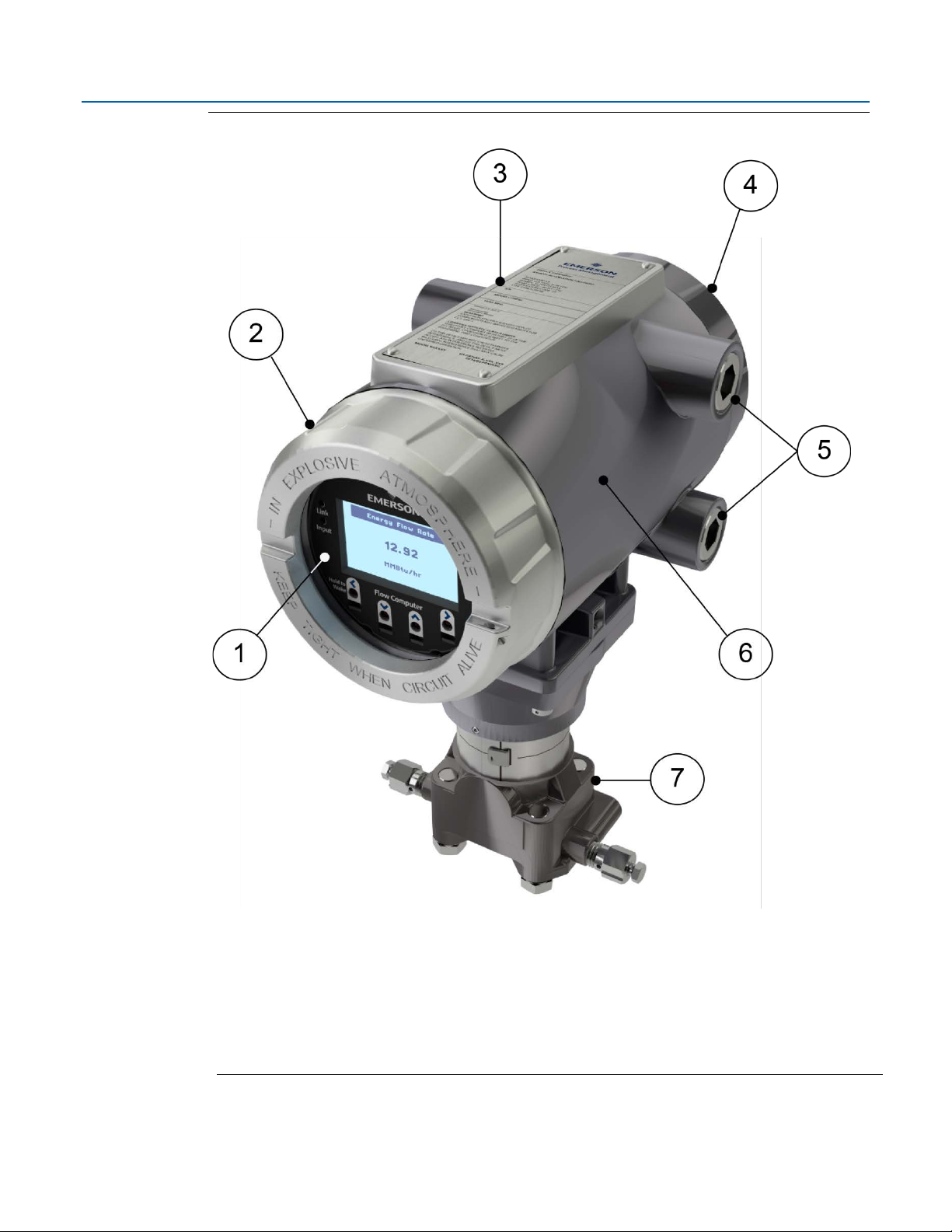
1
HMI module
2
Front end cap (cover)
3
Data plate
4
Rear end cap (cover)
5
Conduit fittings
6
Enclosure
7
Sensor module
D301752X012
February 2021
Figure 1-1: FB1100 Flow Computer
2 Introduction
Safety Labels
DANGER
WARNING
CAUTION
SAFETY FIRST
This product may display safety label(s) to identify potential hazards. The same types of notices
appear within the documentation. Whenever you see an exclamation point (!) enclosed within a
triangle (shown to the left), consult the documentation for additional safety information about the
hazard and how to avoid it. The labels used are:
Emerson FB1100 Flow Computer Instruction Manual
D301752X012
February 2021
MAY CAUSE DEATH
Observe all precautionary signs posted on the equipment.
Failure to do so may result in death or serious injury to personnel.
DANGER TO PERSONNEL AND EQUIPMENT
Observe all precautionary signs posted on the equipment.
Failure to do so may result in injury to personnel or cause damage to the equipment.
MAY CAUSE INJURY TO PERSONNEL OR DAMAGE EQUIPMENT.
Observe all precautionary signs posted on the equipment.
Failure to do so may result in injury to personnel or cause damage to the equipment.
Features
Introduction 3
General instructions and safety reminders.
The FB1100 Flow Computer includes the following key features:
Enclosure suitable for use in Class I Division 1 explosion proof and Ex db Zone 1 flame-proof
environments
Enclosure suitable for use in Class I Division 2 non-incendive and Ex nA Zone 2 non-sparking
environments
Integral multi-variable sensor for measurement of Pressure (P) and Differential Pressure (DP)
Connections for customer-supplied resistance temperature detector (RTD) for measurement
of temperature (T)
Single digital output

Emerson FB1100 Flow Computer Instruction Manual
Memory
Usage
8 MB SRAM
Holds in-use configuration, current state of all variables
Holds firmware image, historical logs, configuration backup (if saved to flash),
D301752X012
February 2021
Power from a DC power supply, a lithium battery, or an optional lead acid battery/solar panel
combination
Serial communication options for RS-232, RS-485 (2-wire), RS-485/422 (4-wire).
HMI module with optional display and back light for local operator interaction
Optional Wi-Fi
from a laptop without physical cable connection
Application software supports AGA3, AGA8, ISO 5167, ISO 6976, and API 21.1 calculations in
U.S., metric, or other natural gas standard units
Support for one-year autonomous measurement without external power (lithium battery
option)
®
transceiver (802.11 b/g) for field technician to access the flow computer
Central Processing Unit (CPU)
The flow computer’s CPU is a NXP® Kinetis® K61 series CPU with an ARM® Cortex® M4 processor
that operates at 4 to 60 MHz depending on the power mode. The CPU runs the Micrium operating
system.
1.3.1 Memory
The flow computer includes both static and flash memory.
Table 1-1: Memory
128 MB Flash
and the executing program
Explosion-proof Enclosure
The FB1100 Flow Computer includes an explosion-proof enclosure made of either aluminum or
stainless steel. The enclosure consists of the main housing, two threaded covers, and four conduit
entry points.
The four conduit entry points are ¾ in NPT pipe threaded holes that permit entry of field conduit
for I/O and communication wiring. ATEX installations use a ¾ in NPT to M20 thread reducer.
Unused apertures shall be closed with suitable blanking elements.
The FB1100 Flow Computer can operate in an unprotected outdoor environment. Wiring for I/O,
communications, and power enters the enclosure through the four conduit fittings with
appropriate protective seals and connects to the terminal plate.
The front end cap (cover) provides a viewing window for the HMI module. You can access the
terminal plate by removing the rear end cap (cover).
4 Introduction
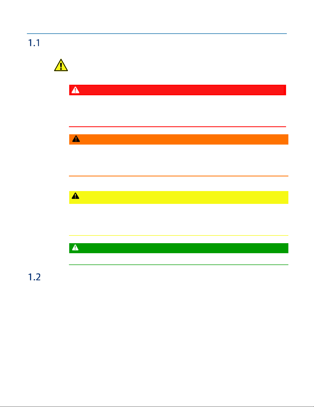
The FB1100 Flow Computer has North American certification for Class I Division 1 Groups C and D
1
Retaining clamp (For ATEX & IEC approved products only)
2
Tie holes in end caps
3
Tie holes in coupling screws
(explosion proof) and Class I Division 2 Groups A, B, C and D (non-incendive) hazardous locations or
non-hazardous locations. See Appendix A and Appendix B for more information.
The FB1100 Flow Computer has European certification for EExd Zone 1 (flame-proof) and EExd
Zone 2 (non-sparking) hazardous locations or non-hazardous locations. See Appendix C and
Appendix D for more information.
Details on certification information are included on the data plate screwed to the top of the
enclosure.
1.4.1 Physical Security
The flow computer end caps include retaining clamps for ATEX/IEC applications. In addition, if local
regulations require it, you can wire a tamper-resistant seal using the tie holes located in the front
and rear end caps, and in the coupling screws.
Figure 1-2: Retaining Clamps and Tie Holes for Tamper-resistant Seals
Emerson FB1100 Flow Computer Instruction Manual
D301752X012
February 2021
Introduction 5

Emerson FB1100 Flow Computer Instruction Manual
Option
Usage
External DC Power
Lead Acid Battery Pack
6.0 Vdc
Lithium Battery Pack
10 Vdc
D301752X012
February 2021
I/O
The flow computer comes with base I/O from both the CPU and the built-in multi-variable (MV)
sensor. Base I/O consists of:
Pressure (P) input from the MV sensor
Differential pressure (DP) input from the MV sensor
Connections for temperature (T) input from a customer-supplied RTD
Single general purpose digital output (DO) - for use with an odorizer or other device
Power Options
You can power the flow computer using an external DC input, an internal battery, or an internal
rechargeable battery connected to a solar panel.
Important
Use only batteries supplied with the flow computer or sold by Emerson Remote Automation
Solutions as spare parts for this flow computer. If you substitute a battery you obtain elsewhere
will void your certification unless it is the identical part from the same manufacturer as that
supplied with the flow computer from Emerson.
you
Table 1-2: Power Options
Supply
5.7 Vdc to 30 Vdc external supply (Max power at 10 watts)
4.5Ah
Not suitable with ATEX or IECEx applications
Can be optionally charged by a 6-watt solar panel
41 Ah (approximate)
Not suitable with ATEX or IECEx applications
Required when using autonomous measurement mode
In autonomous measurement mode allows operation for one year
6 Introduction

Communications
Port
Type
Use
COM1 Serial communications
RS-232, RS-485 (2-wire), RS-485/422 (4-wire)
COM2 Serial communications
RS-232 or RS-485 (2-wire) communication to
COM3 Serial communications
RS-232 or RS-485 (2-wire) communication to
The flow computer includes three serial communication ports. The serial ports allow
communication using DNP3, Modbus, BSAP, and ROC protocols.
Table 1-3: Serial Ports
Software-selectable for RS-232, RS485 (2-wire), RS-485/422 (4-wire)
operation
4-wire
Software-selectable for RS-232, or
RS-485 (2-wire) operation
2-wire
Emerson FB1100 Flow Computer Instruction Manual
D301752X012
February 2021
communication to host or other devices. 4wire used with external radio.
host or other devices.
Software-selectable for RS-232, or
RS-485 (2-wire) operation
2-wire
host or other devices.
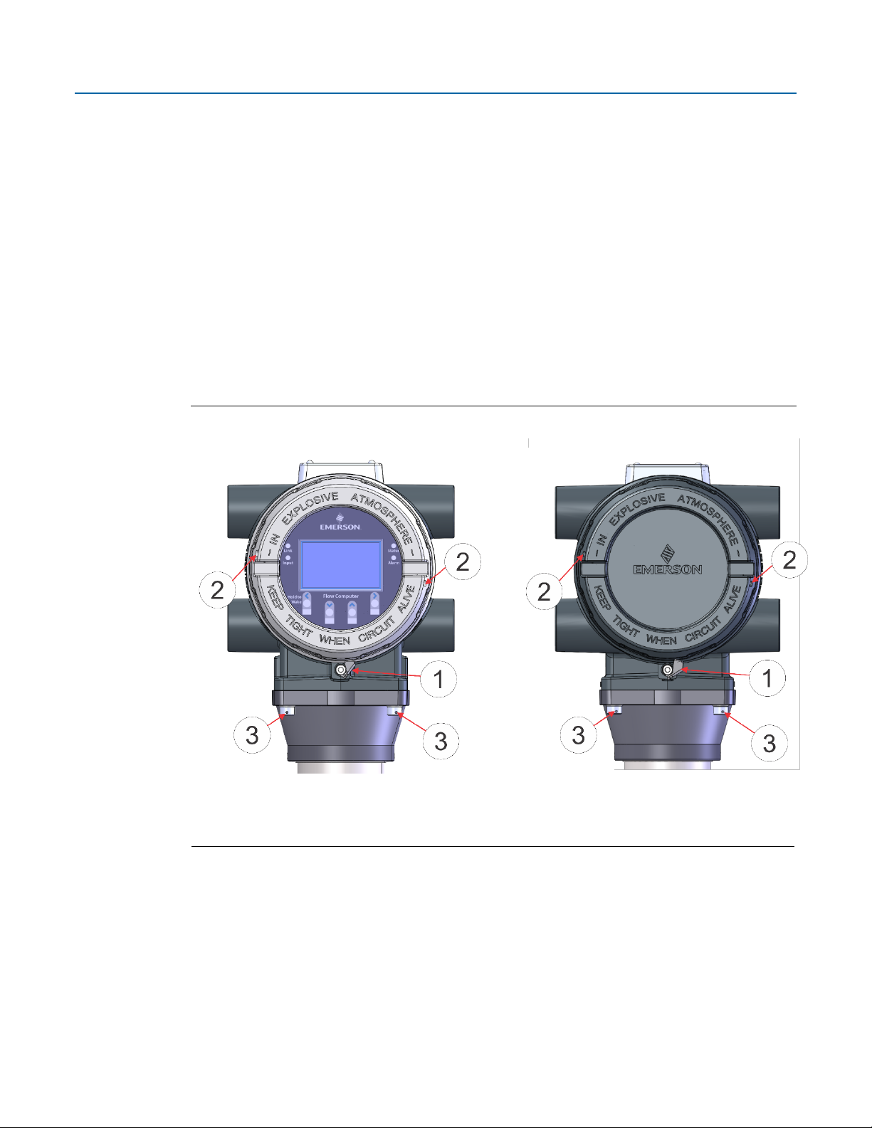
Human-Machine Interface (HMI) Module
The flow computer includes an HMI module with an optional liquid crystal display (LCD) for local
operator access to the device. The LCD, if present, shows a series of menus that sequentially display
the current values of particular process variables. A configuration parameter in FBxConnect
determines whether you must log in first to view the menus. If required, you log in by selecting
alphanumeric characters by scrolling through a list until you select the correct character.
The HMI module includes four LEDs to provide status information. Units with the display include
four infrared (IR) buttons for operator interaction.
To conserve power, the HMI module enters sleep mode after a period of inactivity. Sleep mode
disables FBxWifi communication. In FBxConnect, you can configure the number of minutes of
inactivity triggering sleep mode through the LCD Sleep Time parameter. Setting this parameter to
0 disables sleep mode which keeps the HMI module on but uses significantly more power.
Introduction 7
Emerson FB1100 Flow Computer Instruction Manual
D301752X012
February 2021
Figure 1-3: HMI Module with LCD
Figure 1-4: HMI Module without LCD
Note
If your flow computer does not include the LCD option, you still have the status LEDs and a single IR
button for waking up the device (shown in Figure 1-4).
FBxWifi™ Communications
The flow computer has an optional Wi-Fi® transceiver (FBxWifi) that enables you to connect via a
laptop or tablet from some small distance away.
This capability allows an operator to potentially remain outside the hazardous location and still
communicate with the flow computer. The operator's laptop must have Wi-Fi capability, line-ofsight access to the HMI module, and must be loaded with FBxConnect configuration software.
Once connected, the operator can view process values, edit configuration parameters, and collect
logs.
Note
The FBxWifi electronics reside inside the HMI module. The HMI module must be awake to use
FBxWifi communications You can wake it up manually by holding a finger against the front cover
glass over the Hold to Wake button (the left-most button) for typically from five to ten seconds.
8 Introduction

Emerson FB1100 Flow Computer Instruction Manual
Software Tools
FBxConnect provides a series of wizards that allow you to perform configuration activities for the
flow computer. You connect a PC running FBxConnect to the flow computer using one of the
communication ports or through a wireless connection. You can then:
Set parameters within your application
Configure I/O channels
Specify the serial communication method for a port (RS-232 to RS-485) as needed
View or collect audit trail information such as alarm, event, or historical logs
Update system firmware
Autonomous Measurement Mode
You can configure the FB1100 Flow Computer to operate as a low power measurement device that
operates independently for one year. In this autonomous measurement mode, the flow computer
operates similarly to earlier generation chart recorders, collecting data from non-critical, low-flow
applications and storing it for later retrieval.
D301752X012
February 2021
Autonomous measurement mode supports collection of data from the multi-variable sensor and
RTD only. This mode requires the lithium battery pack; no external power supply is required.
You can interact with the device through the HMI module's infrared buttons or through a laptop
running FBxConnect. To maintain low power consumption for the battery, using this mode limits
you to 30 minutes of interaction per month.
See Appendix E for more information.
RoHS2 Compliance
Device with Integral MVS:
RoHS (2) EU Directive 2011/65/EU: This product may be considered out-of-scope when used for
the intended design purpose in a Large Scale Fixed Installation (LSFI).
Consult https://www.emerson.com/compliance for up-to-date product information.
Introduction 9

Emerson FB1100 Flow Computer Instruction Manual
D301752X012
February 2021
10 Introduction

Section 2: Installation
This section covers the following topics:
Hazardous Locations
Environmental Specifications
Required Tools
Site Considerations
General Wiring Guidelines
Front or Rear End Caps
Mounting the Enclosure
Grounding the Device
Terminal Plate
Power Modes
Emerson FB1100 Flow Computer Instruction Manual
D301752X012
February 2021
Connecting Power
Installing the Optional Solar Panel
Connecting Communication Ports
Connecting the RTD
Wiring the Digital Output
The flow computer ships from the factory fully assembled, except for the optional solar panel
assembly.
2.1 Hazardous Locations
The housing for the FB1100 Flow Computer is an explosion-proof case designed to operate in
hazardous locations.
For North America the FB1100 Flow Computer has certifications for Class I, Division 1 (Groups C &
D) explosion-proof, Class I Division 2 (Groups A, B, C & D) non-incendive, and non-hazardous
locations only. Appendix A contains special information for Class I Division 2 installations; Appendix B
contains special information for Class I Division 1 installations.
For Europe the FB1100 Flow Computer has certifications for Ex db Zone 1 flame-proof and for Ex nA
Zone 2 non-sparking installations and non-hazardous locations only. Appendix C contains special
information for Ex nA Zone 2 installations; Appendix D contains special information for Ex db Zone 1
installations.
All certifications are listed on the data plate located on the top of the device.
Installation 11

Emerson FB1100 Flow Computer Instruction Manual
Specification
Range
-40°C to +80 °C (-40 °F to +176 °F) - no battery, C1D1/C1D2
Maximum Process Connection
Humidity
5% to 95% non-condensing
Vibration
2g over 10 to 150 Hz; 1g over 150 to 200 Hz
Tool
Use
Torque wrench
For bolting/mounting the flow computer
3 mm hexagonal wrench
For screw for M4 x 0.7 end cap retaining clamp
9/16 in hexagonal wrench
For installing/removing ¾ in NPT conduit plugs
1 1/16 in combination wrench
For installing/removing ¾ in NPT to M20 thread
#1 Phillips-head screwdriver
For screws on HMI module
#2 Phillips-head screwdriver
For screws on other modules and boards
1/8 inch flat-head screwdriver
For 5.08 mm pitch terminal block connections
Laptop PC running Field Tools with FBxConnect
2.2 Environmental Specifications
This section summarizes the environmental specifications for the device. For full details, refer to
the product data sheet FB1100 Flow Computer (D301781X012).
Table 2-1: Environmental Specifications
-40°C to +80 °C (-40°F to +176 °F) - lead acid battery, C1D1/C1D2
Ambient Temperature
-40°C to +80 °C (-40 °F to +176 °F) - lithium battery, C1D1/C1D2
-40°C to +80 °C (-40 °F to +176 °F) - no battery, ATEX/IEC Ex db
-40°C to +80 °C (-40 °F to +176 °F) - no battery, ATEX/IEC Ex nA
D301752X012
February 2021
Temperature
2.3 Required Tools
Certain tools and equipment are required for installing and servicing the flow computer.
Table 2-2: Required Tools
2.5 mm hexagonal wrench For manipulating rotation set screw
120 °C (248 °F)
(ATEX required)
configuration software
12 Installation
reducer (ATEX required)
For software configuration

Emerson FB1100 Flow Computer Instruction Manual
2.4 Site Considerations
The flow computer must reside in an accessible location for configuration and service. Refer to the
dimensional drawings for information on the space required.
Ensure the installation location provides easy access to the HMI module.
If your unit includes the optional solar panel, ensure the installation location provides
sufficient space to mount the solar panel and adequate sunlight to charge the battery.
If your unit includes the optional FBxWifi ensure the installation location provides line-ofsight access to the transceiver.
Figure 2-1: FB1100 Flow Computer Dimensions – Multivariable Sensor
D301752X012
February 2021
Installation 13

2.5 General Wiring Guidelines
1
End Cap
2
Screw
3
Retaining Clamp
The flow computer’s pluggable terminal blocks use compression-type terminals that
accommodate wire between 28 and 12 AWG.
When making a connection, insert the bare end of the wire (approx. 1/4" max) into the clamp
adjacent to the screw and secure the screw.
To prevent shorts, ensure that no bare wire is exposed.
Allow some slack in the wire while making terminal connections. Slack makes the wires more
manageable and helps minimize mechanical strain on the terminal blocks.
Use twisted pair, shielded and insulated cable for communication and I/O wiring to minimize
signal errors caused by electromagnetic interference (EMI), radio frequency interference
(RFI), and transients. When using shielded cable, ground all shields at only one point in the
appropriate system. This prevents circulating ground current loops that can cause signal
errors.
2.6 Front or Rear End Caps
Emerson FB1100 Flow Computer Instruction Manual
D301752X012
February 2021
The flow computer includes two threaded covers (end caps). The front end cap includes a window
for viewing the HMI module; the rear end cap provides access to the terminal plate for power and
I/O wiring.
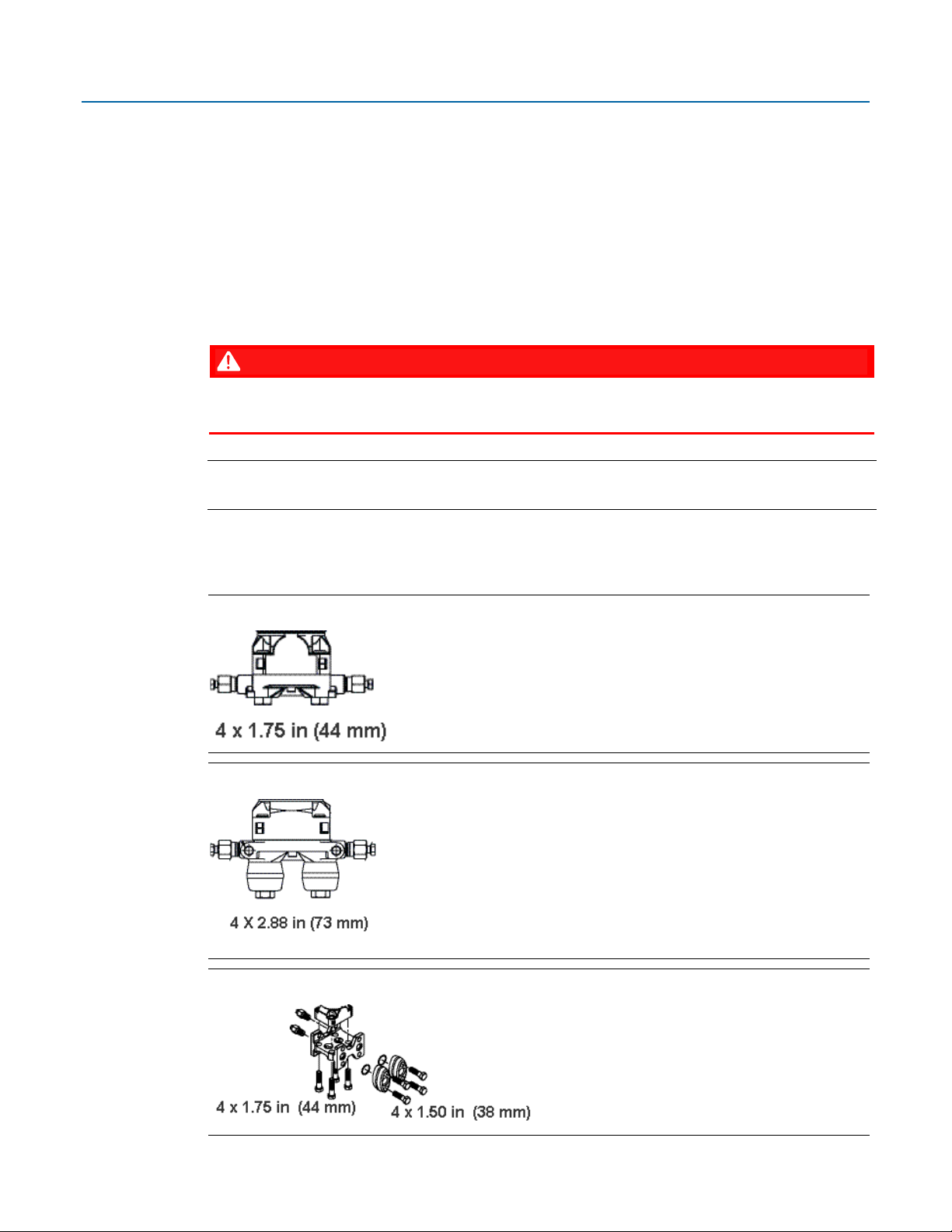
2.6.1 Removing/Replacing Retaining Clamp on End Caps
For flameproof ATEX/IEC applications, each end cap includes a retaining clamp which screws down
to prevent the end cap from being unscrewed.
Figure 2-2: Front End Cap with Retaining Clamp Fitted
14 Installation

Emerson FB1100 Flow Computer Instruction Manual
DANGER
D301752X012
February 2021
Figure 2-3. Retaining Clamp in Place
To loosen or tighten the screw, use a 3mm hexagonal wrench. When tightening, torque to 12 in-lbs
(1.4 N m).
Figure 2-4. Retaining Clamp and Screw
2.6.2 Removing the Front or Rear End Caps
EXPLOSION HAZARD: Never remove end cap(s) in a hazardous location. Removing end cap(s) in a
hazardous location could result in an explosion.
Note
If you need more leverage place a long screwdriver or other appropriate tool across the two
notches in the end cap to act as a pry bar (see Figure 2-5).
Figure 2-5: Removing or Tightening the End Cap with Long Screwdriver
Installation 15
Remove the retaining clamp (if present). (See Section 2.6.1.)
1.
Grasp the end cap (front or rear).
2.
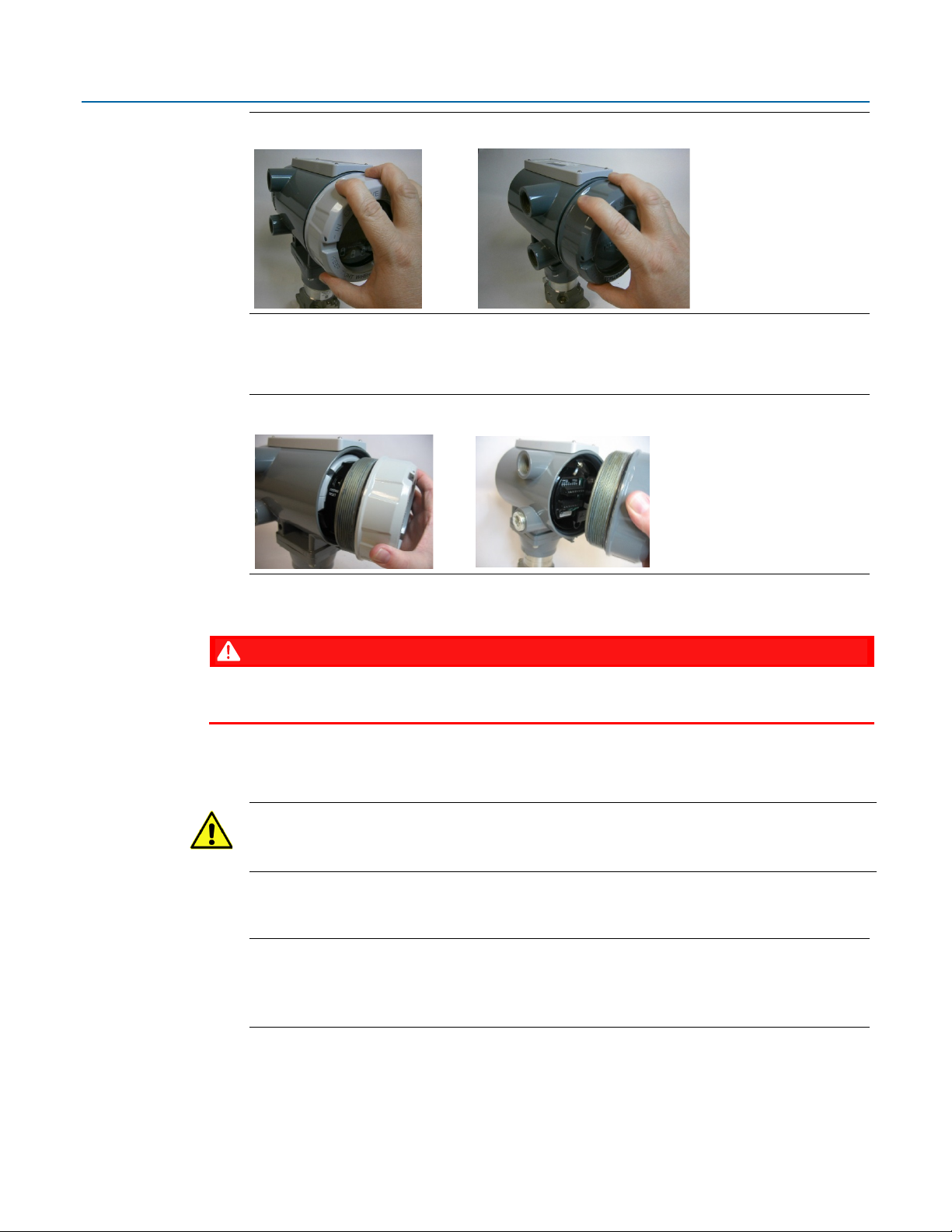
Emerson FB1100 Flow Computer Instruction Manual
DANGER
D301752X012
February 2021
Figure 2-6: Front (left) and Rear (right) End caps
Unscrew the end cap turning it counter-clockwise until it comes off. Set it aside in a safe
3.
location.
Figure 2-7: Front (left) and Rear (right) End Caps Removal
2.6.3 Replacing the Front or Rear End Caps
EXPLOSION HAZARD: Ensure the area in which you perform this operation is non-hazardous.
Performing this operation in a hazardous area could result in an explosion.
Grasp the end cap (front or rear).
1.
2.
Carefully align the end cap threads with the threads of the enclosure.
Important
When replacing the rear end cap, ensure wires connecting to the terminal plate do not get
crimped or caught between the end cap threads and the enclosure.
3.
Screw the end cap clockwise (eight full turns) until it is tightly sealed to the enclosure.
Replace the retaining clamp (if required). (See Section 2.6.1.)
4.
Note
If you need more leverage place a long screwdriver or other appropriate tool across the two
notches in the end cap to act as a pry bar (see Figure 2-5).
2.7 Mounting the Enclosure
You can mount the flow computer either directly to a manifold on the pipeline or indirectly on a
two-inch pipe or pole.
16 Installation
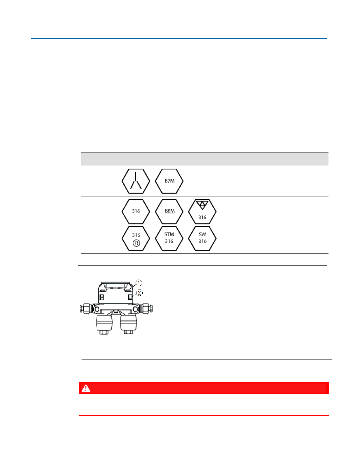
Installations use either a traditional mounting kit or a coplanar mounting kit.
DANGER
2.7.1 Bolting Considerations
If the flow computer installation requires assembly of a process flange, a manifold, or flange
adapters, follow these assembly guidelines to ensure a tight seal for optimal performance
characteristics of the flow computer.
Only use bolts supplied with the flow computer or sold by Emerson Remote Automation Solutions
as spare parts. Refer to the figure for common flow computer assemblies with the bolt length
required for proper flow computer installation.
Emerson FB1100 Flow Computer Instruction Manual
D301752X012
February 2021
EXPLOSION HAZARD: Ensure the area in which you perform this operation is non-hazardous.
Performing this operation in a hazardous area could result in an explosion.
Note
For all other manifolds, contact your local Emerson Sales office or Emerson Impact Partner.
Bolts are typically carbon steel or stainless steel. Confirm the material by viewing the markings on
the head of the bolt and referencing the figure. If bolt material is not shown in the figure, contact
your local Emerson Remote Automation Solutions representative for more information.
Figure 2-8: Transmitter with Coplanar Flange
Figure 2-9: Transmitter with Coplanar Flange and Optional Flange Adapters
Installation 17
Figure 2-10: Transmitter with Traditional Flange and Optional Flange Adapters
Emerson FB1100 Flow Computer Instruction Manual
Bolt Material
Head markings
Initial Torque
Final Torque
1
Bolt
2
Sensor module
DANGER
Use the following bolt installation procedure:
Carbon steel bolts do not require lubrication. Stainless steel bolts are factory-coated with a
1.
lubricant to ease installation. Do not apply any additional lubricant when installing either
type of bolt.
Finger-tighten the bolts.
2.
Torque the bolts to the initial torque value using a crossing pattern. See Table 2-3 for initial
3.
torque value.
Torque the bolts to the final torque value using the same crossing pattern. See Table 2-3 for
4.
final torque value.
Verify that the flange bolts protrude through the sensor module before applying pressure.
5.
Table 2-3: Torque Values for the Flange and Flange Adapter Bolts
D301752X012
February 2021
Carbon
Steel (CS)
Stainless Steel
(SST)
Figure 2-11: Proper Bolt Installation
300 in. -lbs.
(33.9 N m)
150 in. -lbs.
(16.9 N m)
650 in. -lbs.
(73.4 N m)
300 in. -lbs.
(33.9 N m)
2.7.2 O-rings with Flange Adapters
18 Installation
Failure to install proper flange adapter O-rings may cause process leaks, which can result in death
or serious injury. Only use the O-ring that is designed for its specific flange adapter.
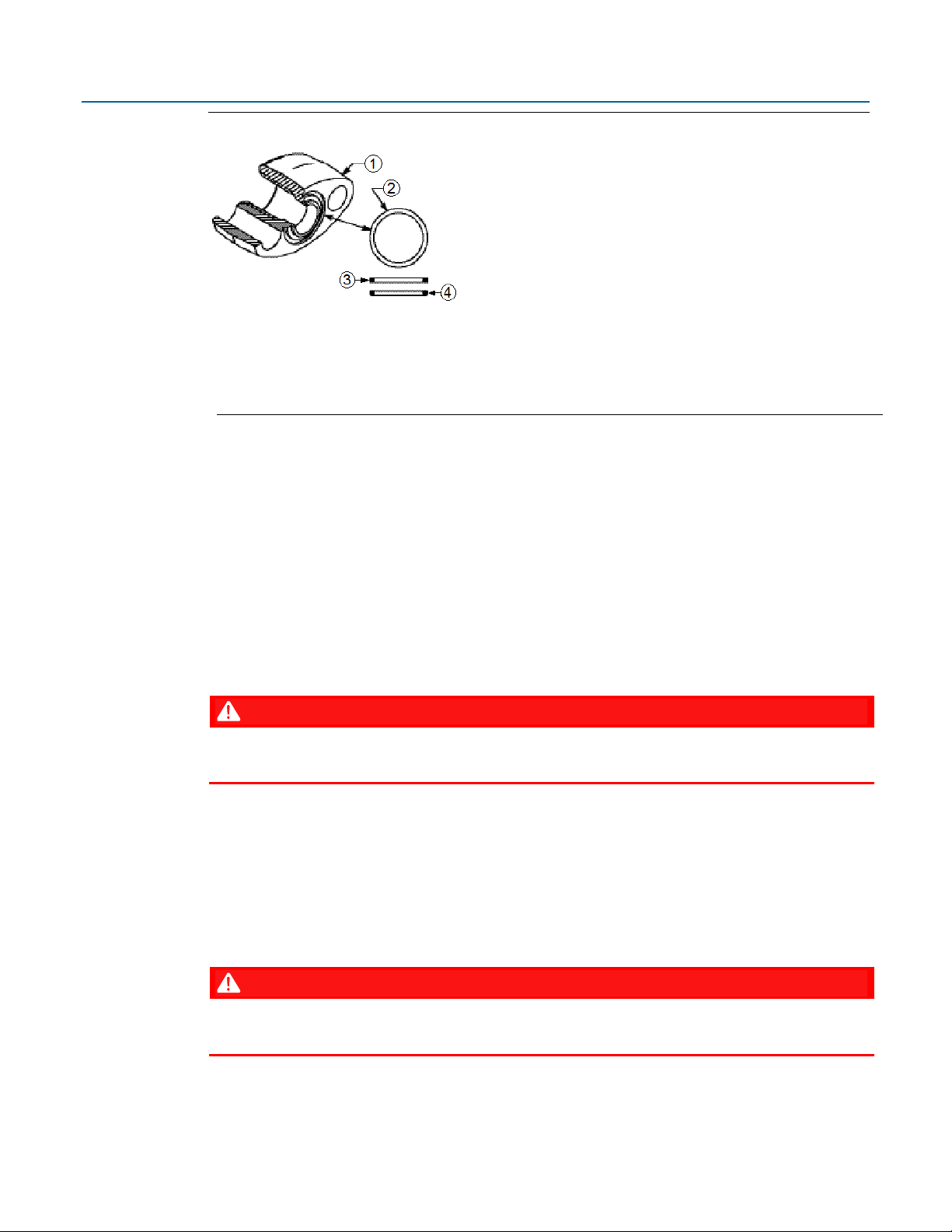
Emerson FB1100 Flow Computer Instruction Manual
1
Flange
2
O-ring
3
Square PTFE-based profile
4
Round Elastomer profile
DANGER
DANGER
Figure 2-12: O-rings with Flange Adapters
Whenever the flange or adapters are removed, visually inspect the O-rings.
1.
Replace the O-rings if there are any signs of damage, such as nicks or cuts.
2.
If the O-rings are replaced, re-torque the flange bolts and alignment screws after installation
3.
to compensate for seating of the O-rings.
D301752X012
February 2021
2.7.3 Direct Mount
Direct mount installations use either a traditional mounting kit or a coplanar mounting kit. Mount
the flow computer directly to the natural gas pipeline only if the pipeline includes a process
manifold.
EXPLOSION HAZARD: Ensure the area in which you perform this operation is non-hazardous.
Performing this operation in a hazardous area could result in an explosion.
Place taps in the top or side of the line.
1.
Mount the flow computer beside or above the taps.
2.
2.7.4 Indirect Mount
You can mount the flow computer to a two-inch pipe or pole. Indirect mount can use the coplanar,
or traditional flange mounting kits.
EXPLOSION HAZARD: Ensure the area in which you perform this operation is non-hazardous.
Performing this operation in a hazardous area could result in an explosion.
Installation 19
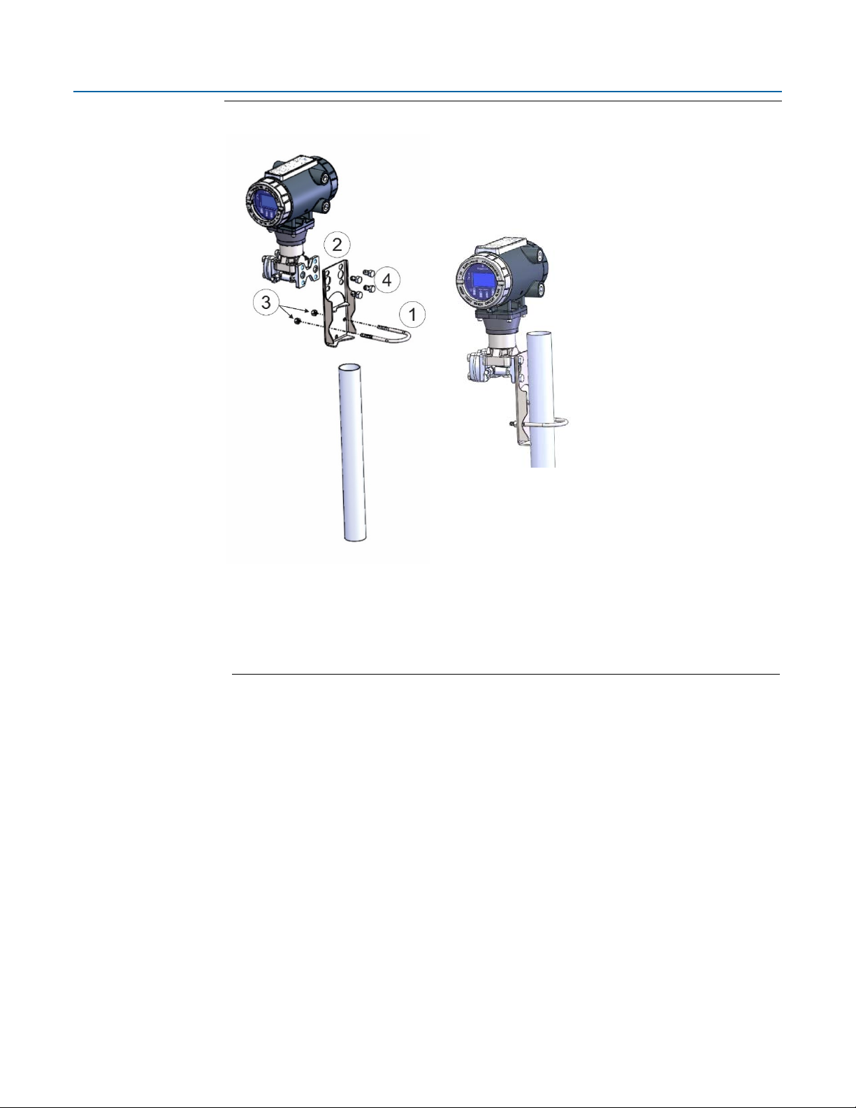
Emerson FB1100 Flow Computer Instruction Manual
1
2.0 in. pipe diam. U-bolt assembly (5/16-18 x 4.0 LG) with (2) nuts (item 3)
2
Mounting bracket
3
Apply Loctite® 222™ Low Strength Purple Threadlocker to nuts. Torque nuts to 30
4
7/16-20 x .625 cs/zinc cobalt screws (4). Torque to 30 in-lbs (3.4 N m)
Figure 2-13: Traditional Flange Mounting Kit
D301752X012
February 2021
in-lbs (3.4 N m)
20 Installation
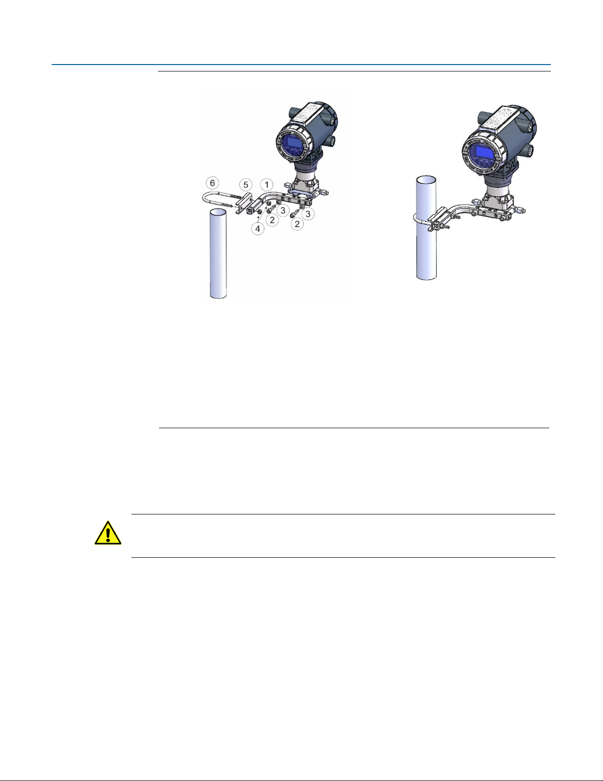
Figure 2-14: Coplanar Mounting Kit
1
Tubular L-shaped bracket
2
3/8-16 x 1 ½ in socket head wire lockable screw (2) – Apply Killark® LUBG-6 Thread
Lubricant to threads. Torque screws to 30 in
3
Split 3/8 lock washer (2)
4
5/16-18 keps nut (2). Apply Loctite 222 Low Strength Purple Threadlocker to nuts.
Torque nuts to 30 in
5
U-bolt bracket
6
2-inch diameter pipe U-bolt
Emerson FB1100 Flow Computer Instruction Manual
D301752X012
February 2021
-lbs (3.4 N m)
2.7.5 Rotating the Housing
-lbs (3.4 N m)
To improve accessibility to the HMI module or to ease wiring, you can optionally rotate the
housing.
Important
Never rotate the housing more than 180 degrees from its original (as-shipped) position. Overrotation can break electronics within the unit.
Installation 21

Emerson FB1100 Flow Computer Instruction Manual
1
Set Screw (one each side)
DANGER
Figure 2-15: Housing Rotation Set Screw (1 each side)
D301752X012
February 2021
2.8 Grounding the Device
22 Installation
EXPLOSION HAZARD: Ensure the area in which you perform this operation is non-hazardous.
Performing this operation in a hazardous area could result in an explosion.
Loosen the two housing rotation set screws.
1.
Rotate the housing
2.
Re-tighten the two housing rotation set screws. Torque to 6 in-lbs. (0.7 N m).
3.
The flow computer includes a grounding lug on the terminal plate.
no more than 180 degrees from its original (as-shipped) position.
 Loading...