

Page 1
026-1614 Rev 4 5-JAN-2013
E2 Installation and Operation Manual for RX Refrigeration,
BX HVAC, and CX Convenience Store Controllers
Applicable to E2 firmware versions 4.0 and above
Page 2

Page 3

Emerson Climate Technologies Retail Solutions
1065 Big Shanty Road NW,
Kennesaw, GA 30144, USA
Phone 770-425-2724
Fax 770-425-9319
E2 FIRMWARE VERSION
4.05F01
FCC COMPLIANCE NOTICE
This device complies with Part 15 of the FCC
lowing two conditions: (1) this device may not cause harmful interference, and (2) this
device
must accept any interference received, including interference that may cause
undesired operation.
CE COMPLIANCE NOTICE
Class A Product Information for E2 Controllers:
The Emerson Retail Solutions Einstein and E2 controllers are Class A
domestic environment this product may cause radio interference in which case the user
may be required to take adequate measures. This covers:
Rules. Operation is subject to the fol-
Suite 100
products. In a
• All E2 family product types: RX - Refrig
BX - Building/HVAC Controller (845-xxxx), CX- Convenience Store
Con
troller (845-xxxx), and all version models: (300, 400, 500).
eration Controller (845-xxxx),
Page 4

Page 5

TABLE OF CONTENTS
1 INTRODUCTION...................................................................................................................................................... 1-1
1.1 THE E2 REFRIGERATION CONTROLLER (RX)............................................................................................................ 1-1
1.2 THE E2 BUILDING CONTROLLER (BX)...................................................................................................................... 1-2
1.3 THE E2 CONVENIENCE STORE CONTROLLER (CX)................................................................................................... 1-3
1.4 NETWORKING OVERVIEW.......................................................................................................................................... 1-4
1.4.1 E2 I/O Network .................................................................................................................................................. 1-4
1.4.2 The E2 Echelon Lonworks Network................................................................................................................... 1-5
1.4.3 Interconnection With Other E2s ........................................................................................................................ 1-5
1.5 DOCUMENTATION OVERVIEW ................................................................................................................................... 1-6
1.6 ON-LINE HELP SYSTEM OVERVIEW .......................................................................................................................... 1-7
1.7 SOFTWARE LICENSING............................................................................................................................................... 1-7
2 HARDWARE OVERVIEW...................................................................................................................................... 2-1
2.1 E2 HARDWARE .......................................................................................................................................................... 2-1
2.1.1 E2 Main Processor Board (CPU)...................................................................................................................... 2-2
2.1.2 E2 Processor Interface Board (PIB).................................................................................................................. 2-2
2.1.3 E2 Keypad.......................................................................................................................................................... 2-2
2.1.4 LEDs................................................................................................................................................................... 2-2
2.2 I/O NETWORK BOARDS AND PERIPHERALS............................................................................................................... 2-3
2.2.1 The Gateway Board ....................................................................... .................................................................... 2-3
2.2.2 MultiFlex Boards ............................................................................................................................................... 2-4
2.2.2.1 MultiFlex 16 Input Board ........................................................................................................................................ 2-4
2.2.2.2 MultiFlex Combination Input/Output Boards .......................................................................................................... 2-4
2.2.2.3 MultiFlex CUB ........................................................................................................................................................ 2-6
2.2.2.4 MultiFlex RTU (BX and CX Only)......................................................................................................................... 2-6
2.2.2.5 MultiFlex Rooftop Control Board (RCB) (BX and CX Only) ................................................................................ 2-6
2.2.2.6 MultiFlex PAK Board......................... ............................. ............................. ........................................................... 2-6
2.2.3 The MultiFlex ESR Board.................................................................................................................................. 2-7
2.2.4 Hand-held Terminal (P/N 814-3110)................................................................................................................. 2-7
2.2.5 The 8RO and 8ROSMT Relay Boards................................................................................................................ 2-8
2.2.6 4AO Analog Output Board................................................................................................................................. 2-9
2.2.7 8DO Digital Output Board and PMAC II Anti-Sweat Controller ..................................................................... 2-9
2.3 ECHELON NETWORK BOARDS AND PERIPHERALS................................................................................................... 2-10
2.3.1 The 16AIe (Discontinued)................................................................................................................................ 2-10
2.3.2 The 8ROe (Discontinued)................................................................................................................................. 2-10
2.3.3 EC-2s................................................................................................................................................................ 2-11
2.3.4 CC-100 Case Controllers and CS-100 Case Circuit Controllers.................................................................... 2-11
2.3.5 TD3 Temperature Display ............................................................................................................................... 2-12
2.3.6 Facility Status Display (FSD).......................................................................................................................... 2-12
3 MOUNTING............................................................................................................................................................... 3-1
3.1 MOUNTING THE E2.............................................................................................. ...................................................... 3-1
3.1.1 Standard Mount.................................................................................................................................................. 3-1
3.1.2 Recessed Mount.................................................................................................................................................. 3-1
3.1.3 Retrofit Mounting............................................................................................................................................... 3-2
3.1.4 Blank Face ......................................................................................................................................................... 3-3
3.2 MOUNTING I/O BOARDS............................................................................................................................................ 3-3
3.2.1 Single/Double Enclosures................................................................................................................................. 3-3
3.2.2 Boards Without Enclosures (Snap Track).......................................................................................................... 3-4
E2 RX/BX/CX I&O Manual Table of Contents • v
Page 6

3.3 ECHELON DEVICES .................................................................................................................................................... 3-5
3.3.1 CC-100 Case Controller and CS-100 Case Circuit Controller......................................................................... 3-5
3.3.2 MultiFlex ESR.................................................................................................................................................... 3-5
3.3.3 TD3..................................................................................................................................................................... 3-5
3.4 COM3 INTERNAL MODEM PLUG-IN CARD
(P/N 638-3362).................................................................................................................................................................. 3-5
3.4.1 Two-Channel and Four-Channel Repeaters ...................................................................................................... 3-6
3.4.1.1 Mounting Repeaters Overview ................................................................................................................................ 3-6
3.4.1.2 Mounting the Two-Channel Repeater...................................................................................................................... 3-6
3.4.1.3 Mounting the Four-Channel Repeater ..................................................................................................................... 3-6
3.5 SENSORS AND TRANSDUCERS.................................................................................................................................... 3-7
3.5.1 Pressure Transducers......................................................................................................................................... 3-7
3.5.1.1 Mounting.................................................................................................................................................................. 3-7
3.5.2 Inside Temperature Sensor................................................................................................................................. 3-7
3.5.2.1 Location ................................................................................................................................................................... 3-7
3.5.2.2 Mounting.................................................................................................................................................................. 3-7
3.5.3 Outside Temperature Sensor.............................................................................................................................. 3-7
3.5.3.1 Location ................................................................................................................................................................... 3-7
3.5.3.2 Mounting.................................................................................................................................................................. 3-7
3.5.4 Insertion Temperature Probe............................................................................................................................. 3-8
3.5.4.1 Location ................................................................................................................................................................... 3-8
3.5.4.2 Mounting.................................................................................................................................................................. 3-8
3.5.5 Supply and Return Air Sensors........................................................................................................................... 3-8
3.5.6 Refrigeration System Temperature Probes and Sensors.................................. .................................................. 3-8
3.5.6.1 Location ................................................................................................................................................................... 3-8
3.5.6.2 Mounting Bullet and Pipe Mount Sensors............................................................................................................... 3-8
3.5.7 Product Temperature Probes....................................................... ...................................................................... 3-9
3.5.8 Humidity Sensors and Humidistats.................................................................................................................... 3-9
3.5.8.1 Indoor RH Sensor .................................................................................................................................................... 3-9
3.5.8.2 Outdoor RH Sensors ................................................................................................................................................ 3-9
3.5.8.3 Duct-mounted Insertion RH Probe ...... ............................. ............................. ........................................................ 3-10
3.5.9 Dewpoint Probe................................................................................................................................................ 3-10
3.5.9.1 Location .................................................................................................................... ............................................. 3-10
3.5.9.2 Mounting..................................................................................................................... ........................................... 3-10
3.5.10 Light Level Sensor.......................................................................................................................................... 3-10
3.5.10.1 Location ............................................................................................................................................................... 3-10
3.5.10.2 Mounting.................................................................................................................................................. ............ 3-10
3.5.11 Liquid Level Sensors...................................................................................................................................... 3-11
3.5.12 Refrigerant Leak Detectors............................................................................................................................ 3-11
4 E2 HARDWARE SETUP.......................................................................................................................................... 4-1
4.1 SETTING UP THE E2 ................................................................................................................................................... 4-1
4.1.1 Enclosure............................................................................................................................................................ 4-1
4.1.2 Main Processor Board ..................................... ............................................. ..................................................... 4-1
4.1.3 Power Interface Board (PIB)........................................................................ ..................................................... 4-2
4.2 POWERING THE E2..................................................................................................................................................... 4-2
4.2.1 RS485 Ports........................................................................................................................................................ 4-2
4.2.2 RS485 Termination Jumpers (MODBUS or I/O Net)......................................................................................... 4-2
4.2.3 Echelon Network Connect.................................................................................................................................. 4-2
4.2.4 Echelon Jumper.................................................................................................................................................. 4-2
4.3 ADD-ON E2 PERIPHERALS......................................................................................................................................... 4-2
4.3.1 Echelon Plug-In Card Kit
(P/N 638-4860) ............................................................................................................................................................. 4-2
4.3.2 COM3 RS232 Plug-In for External Modem (P/N 638-4875) ............................................................................ 4-3
4.3.3 COM3 Internal Modem Plug-In Card (P/N 638-3362) .................................................................................... 4-3
vi • Table of Contents 026-1614 Rev 4 5-JAN-2013
Page 7

4.3.4 Plug-In Digital I/O Network Card (P/N 638-4880)........................................................................................... 4-3
4.3.4.1 LEDs ........................................................................................................................................................................ 4-3
4.3.5 Plug-In Four-Channel Internal Repeater ............................................ .. ............................................................ 4-3
5 SERIAL CONFIGURATION................................................................................................................................... 5-1
5.1 OVERVIEW................................................................................................................................................................. 5-1
5.2 COM PORTS .............................................................................................................................................................. 5-1
5.3 SERIAL DEVICE AND SOFTWARE SETUP.................................................................................................................... 5-1
6 THE RS485 NETWORK AND HARDWARE SETUP.......................................................................................... 6-1
6.1 THE I/O NETWORK .................................................................................................................................................... 6-1
6.1.1 I/O Board Names and Terminology................................................................................................................... 6-1
6.1.2 MultiFlex-Plus (+) Board.................................................................................................................................. 6-2
6.1.2.1 Board Designation ................................................................................................................................................... 6-2
6.1.2.2 Board Calculations................................................................................................................................................... 6-2
6.1.3 Wiring Types...................................................................................................................................................... 6-2
6.1.4 The I/O Network Structure (Daisy Chains)........................................................................................................ 6-2
6.1.5 Network Noise Minimization.............................................................................................................................. 6-3
6.1.6 Network ID Numbers (Board Numbers) ............................................................................................................ 6-3
6.1.7 Setting the Baud Rate......................................................................................................................................... 6-3
6.1.8 Setting the Terminating and Biasing Jumpers................................................................................................... 6-4
6.1.9 Powering the I/O Boards................................................................................................................................... 6-4
6.1.9.1 Wiring Types ........................................................................................................................................................... 6-5
6.1.10 Board Installation............................................................................................................................................ 6-6
6.2 IMC/PRODIGY ROOFTOP UNIT CONTROLLERS.......................................................................................................... 6-6
6.3 MODBUS.................................................................................................................................................................. 6-6
6.3.1 Control Techniques Drive (VSD)....................................................................................................................... 6-6
6.3.2 Copeland Discus with CoreSense Diagnostics (ISD) ................................................ ........................................ 6-7
6.3.3 XR35CX, XR75CX, and XEV22 Case Controllers............................................................................................. 6-7
6.3.3.1 XR75CX-Case Display............................................................................................................................................ 6-7
6.3.4 iPro DAC............................................................................................................................................................ 6-7
6.3.5 Energy Meter...................................................................................................................................................... 6-7
6.3.5.1 Overview.................................................................................................................................................................. 6-7
6.3.5.2 Supported System Types.......................................................................................................................................... 6-8
6.3.6 Modular Refrigerant Leak Detection Sensor (MRLDS) ................................................................................... 6-8
6.3.7 Copeland Discus with CoreSense Protection ................................................................................................... 6-8
6.3.8 Copeland CoreSense Communications.............................................................................................................. 6-8
6.3.9 Light Commercial Thermostat........................................................................................................................... 6-9
6.3.9.1 Thermostat Inputs .................................................................................................................................................... 6-9
6.3.9.2 Advisory and Alarms ............................................................................................................................................... 6-9
6.3.10 Refrigerant Leak Detection System (RLDS)................................................................................................... 6-11
6.3.10.1 Diagnostic Alarms ............................................................................................................................................... 6-12
6.3.11 Copeland Scroll – K5 Refrigeration Compressor.......................................................................................... 6-12
6.3.12 XM Series of Case Controllers...................................................................................................................... 6-12
6.3.12.1 XM670................................................................................................................................................................. 6-12
6.3.12.2 XM679................................................................................................................................................................. 6-12
6.3.12.3 XM678................................................................................................................................................................. 6-12
6.4 BACNET .................................................................................................................................................................. 6-13
6.4.1 BACnet Overview............................................................................................................................................. 6-13
6.4.2 BACnet Communication................................................................................................................................... 6-13
6.4.2.1 Master Slave Token Passing........................................................... ............................. .. . ....................................... 6-13
6.4.2.2 BACnet IP (Internet Protocol)............................................................................................................................... 6-14
6.4.2.3 Discovery ........................................................................................................................................... .................... 6-14
6.4.2.4 Client-Server.......................................................................................................................................................... 6-14
6.4.3 MS/TP Network Connection to E2................................................................................................................... 6-14
E2 RX/BX/CX I&O Manual Table of Contents • vii
Page 8

6.4.3.1 Add and Connect a BACnet Device ...................................................................................................................... 6-14
7 E2 ETHERNET PEER COMMUNICATIONS...................................................................................................... 7-1
7.1 ETHERNET IP CONFIGURATIONS................................................................................................................................ 7-1
7.2 HARDWARE SPECIFICATIONS..................................................................................................................................... 7-1
7.2.1 Components........................................................................................................................................................ 7-1
7.3 SOFTWARE SPECIFICATIONS ...................................................................................................................................... 7-2
7.4 ETHERNET NETWORK LAYOUTS ................................................................................................................................ 7-2
7.4.1 Closed Network Layout...................... ................................................................................................................ 7-2
7.4.2 Open Network Layout......................................................................................................................................... 7-3
7.5 SOFTWARE SETUP...................................................................................................................................................... 7-3
7.6 TROUBLESHOOTING ................................................................................................................................................... 7-4
8 ECHELON NETWORK AND HARDWARE SETUP........................................................................................... 8-1
8.1 OVERVIEW ................................................................................................................................................................. 8-1
8.2 WIRING TYPE............................................................................................................................................................. 8-1
8.3 ECHELON NETWORK STRUCTURING (DAISY-CHAINS).............................................................................................. 8-1
8.3.1 Maximum Number of Echelon Devices.............................................................................................................. 8-2
8.4 DEVICE TERMINATION............................................................................................................................................... 8-2
8.4.1 Using a Termination Block (P/N 535-2715) to Terminate a Daisy Chain................................................. ........ 8-3
8.5 WIRE RESTRICTIONS.................................................................................................................................................. 8-3
8.6 INSTALLING ECHELON DEVICES................................................................................................................................ 8-3
8.6.1 Powering Echelon Devices................................................................................................................................. 8-3
8.7 LEDS ......................................................................................................................................................................... 8-4
8.8 OPEN ECHELON DEVICE CONNECTIVITY................................................................................................................... 8-4
8.8.1 Configuring Echelon Devices............................................................................................................................. 8-4
8.8.1.1 Troubleshooting ....................................................................................................................................................... 8-5
9 INPUT AND OUTPUT SETUP................................................................................................................................ 9-1
9.1 THE 16AI, 8IO, AND MULTIFLEX INPUTS ................................................................................................................. 9-1
9.1.1 Connecting Sensors to Input Boards.................................................................................................................. 9-1
9.1.1.1 Wiring ...................................................................................................................................................................... 9-1
9.1.1.2 Sensor Wiring Types................................................................................................................................................ 9-1
9.1.1.3 Input Type Dip Switches ......................................................................................................................................... 9-1
9.1.2 Power Connection.............................................................................................................................................. 9-2
9.1.3 Input Setup in E2................................................................................................................................................ 9-6
9.1.3.1 Configuring a Point from the Input Definitions/Status Screen................................................................................ 9-6
9.1.3.2 Using the Input Definitions/Status Screen............................................................................................................... 9-7
9.1.3.3 Setting Up Analog Inputs......................................................................................................................................... 9-7
9.1.3.4 Setting Up Digital Inputs......................................................................................................................................... 9-9
9.2 THE 8RO, 8IO, AND MULTIFLEX OUTPUTS ............................................................................................................ 9-10
9.2.1 Wiring Form C Contacts.................................................................................................................................. 9-10
9.2.2 MultiFlex Relay Outputs.................................................................................................................................. 9-10
9.2.3 Setting the Fail-Safe Dip Switch...................................................................................................................... 9-11
9.2.4 Relay Output Test Mode................................................................................................................................... 9-11
9.2.5 Wiring Outputs to Points................................................................................................................................. 9-12
9.2.6 The Output LED............................................................................................................................................... 9-12
9.2.7 Output Setup in E2 ........................................................................................................................................... 9-12
9.2.7.1 Configuring a Point from the Output Definitions/Status Screen ............ .. ................................ ............................. 9-12
9.2.7.2 Using the Output Definitions/Status Screen .......................................................................................................... 9-13
9.2.7.3 Setting Up Digital Outputs.............................................................................................................. ....................... 9-13
9.2.7.4 Setting Up Analog Outputs.................................................................................................................. .................. 9-14
9.3 CC-100 CASE CONTROLLERS.................................................................................................................................. 9-16
9.3.1 Inputs................................................................................................................................................................ 9-16
9.3.2 Power Module Wiring...................................................................................................................................... 9-17
viii • Table of Contents 026-1614 Rev 4 5-JAN-2013
Page 9

9.3.3 Valve Cable...................................................................................................................................................... 9-17
9.4
CCB CASE CONTROLLERS ...................................................................................................................................... 9-18
9.5 ESR8 AND MULTIFLEX ESR VALVE OUTPUT WIRING........................................................................................... 9-18
10 QUICK START...................................................................................................................................................... 10-1
10.1 LOGGING ON ......................................................................................................................................................... 10-1
10.2 CLEANING OUT THE CONTROLLER........................................................................................................................ 10-1
10.3 SETTING NUMBER OF NETWORK DEVICES............................................................................................................ 10-2
10.4 SETTING NUMBER OF APPLICATIONS .................................................................................................................... 10-3
10.5 THE MAIN STATUS (HOME) SCREEN..................................................................................................................... 10-3
10.5.1 Customizing the Home Screen....................................................................................................................... 10-3
10.6 COMMON SCREEN ELEMENTS ............................................................................................................................... 10-4
10.6.1 The Header..................................................................................................................................................... 10-4
10.6.1.1 Header Icons ........................................................................................................................................................ 10-4
10.6.2 The Function Keys ......................................................................................................................................... 10-4
10.6.3 The Help Line................................................................................................................................................. 10-4
10.7 SCREEN TYPES....................................................................................................................................................... 10-5
10.7.1 The Main Menu.............................................................................................................................................. 10-5
10.7.2 Status Screens ................................................................................................................................................ 10-5
10.7.3 The Actions Menu........................................................................................................................................... 10-6
10.7.4 The Setup Screens .......................................................................................................................................... 10-6
10.7.5 System Configuration Menu........................................ ................................................................................... 10-7
10.7.6 The System Information Menu ....................................................................................................................... 10-8
10.8 TIME/DATE SETUP................................................................................................................................................. 10-9
10.8.1 Setting the Time and Date.............................................................................................................................. 10-9
10.9 SET UP MODEM.............................................................................................................................................. ..... 10-10
10.10 SET UP TCP/IP.................................................................................................................................................. 10-11
10.11 SET UP NETWORK BAUD RATES......................................................... .......................................... ................... 10-12
10.11.1 COM1 Serial (RS232) Baud Rate .............................................................................................................. 10-12
10.11.2 I/O Network Baud Rate........................................................... ................................................................... 10-12
10.12 SET UP USER ACCESS ....................................................................................................................................... 10-13
10.12.1 Changing Required User Access Levels .................................................................................................... 10-14
10.12.2 Creating a New User Account ................................................................................................................... 10-14
10.12.3 Deleting a User.......................................................................................................................................... 10-14
10.13 SET UP I/O NETWORK ....................................................................................................................................... 10-15
10.13.1 Specify Number of Boards............................................................................................................... ........... 10-15
10.13.2 Checking Online Status.............................................................................................................................. 10-15
10.14 SET UP ECHELON NETWORK............................................................. .......................................... ...................... 10-16
10.14.1 Specifying Number of Devices ................................................................................................................... 10-16
10.14.2 Commissioning a Device............................................................................................................................ 10-16
10.14.2.1 The Service Button Method.................................................................................................................. ........... 10-17
10.14.2.2 The Manual ID Entry Method.......................................................................................................................... 10-18
10.15 LICENSE MANAGEMENT .................................................................................................................................... 10-19
10.15.1 Web Services.............................................................................................................................................. 10-20
10.16 SET UP ALARMING ............................................................................................................................................ 10-20
10.16.1 Specifying Alarm Reporting Types............................................................................................................. 10-21
10.16.1.1 The Display Line.......................................................................................................................... .................... 10-21
10.16.1.2 The Alarm Output...................................................................................................................... ...................... 10-21
10.16.1.3 Dial-Out ............................................................................................................................ ............................... 10-21
10.16.1.4 The Echelon Network (The Alarm Annunciator)............................................................................................ 10-21
10.16.2 Setting up an E2 to be an Alarm Annunciator ........................................................................................... 10-22
10.16.3 Alarm Dial-Out............................................................................................................... ........................... 10-22
10.16.4 Introduction: Alarm Reporting.................................................................................................................. 10-23
10.17 SET UP GLOBAL DATA...................................................................................................................................... 10-23
E2 RX/BX/CX I&O Manual Table of Contents • ix
Page 10

10.17.1 Priority Settings.......................................................................................................... ................................ 10-24
10.18
SET UP APPLICATIONS....................................................................................................................................... 10-25
10.18.1 Add/Delete an Application..................................................................................................... .................... 10-26
10.18.2 Using and Configuring a Setup Screen...................................................................................................... 10-26
10.18.2.1 The Edit Menu ...................................................................................................................... ........................... 10-27
10.18.2.2 Entering Setpoints............................................................................................................................................ 10-27
10.18.2.3 Navigating the Setup Screen............................................................................................ ............................. ... 10-27
10.18.3 Using the Help Key to get Property Help ............................................................................................ ...... 10-29
11 SOFTWARE OVERVIEW................................................................................................................................... 11-1
11.1 SUCTION GROUPS .................................................................................................................................................. 11-1
11.1.1 Introduction.................................................................................................................................................... 11-1
11.1.2 The (Standard) Suction Group Application ................................................................................................... 11-1
11.1.2.1 Overview of PID Control Strategy ...................................................................................................................... 11-1
11.1.2.2 Variable-Speed Compressors.................................................................................................. ............................ . 11-1
11.1.2.3 Floating Setpoint Control................................ ............................. .. ...................................................................... 11-1
11.1.3 The Enhanced Suction Group Application..................................................................................................... 11-1
11.1.3.1 Learning Mode.......................................................................................................... ............................. .............. 11-2
11.1.3.2 Circuit Load Analysis ........................ ............................. ............................. ........................... ............................. 11-2
11.1.3.3 The Control/Cycles Parameter............................................................................................................................. 11-2
11.1.3.4 Variable-Speed, Digital Scroll, and Digital Discus Compressor Support........................................................... 11-2
11.1.3.5 Floating Suction Control...................................................................................................................................... 11-2
11.1.4 Hardware Overview....................................................................................................................................... 11-2
11.2 CONDENSER CONTROL........................................................................................................................................... 11-3
11.2.1 Air Cooled Condensers .................................................................................................................................. 11-3
11.2.1.1 Air Cooled Strategy ............................................................................................................................................. 11-3
11.2.1.2 Temperature Differential Strategy....................................................................................................................... 11-3
11.2.2 Evaporative Condensers ................................................................................................................................ 11-4
11.2.3 Fan Control.................................................................................................................................................... 11-4
11.2.4 Condenser Split Mode.................................................................................................................................... 11-4
11.2.5 Fast Recovery................................................................................................................................................. 11-4
11.2.6 Hardware Overview....................................................................................................................................... 11-4
11.3 STANDARD CIRCUITS............................................................................................................................................. 11-5
11.3.1 Refrigeration Control..................................................................................................................................... 11-6
11.3.1.1 Temperature Monitor........................................................................................................................................... 11-6
11.3.1.2 Temperature Control............................................................................................................................................ 11-6
11.3.1.3 Line Up(ESR)/Defrost ....................................................................................................... ............................. ..... 11-6
11.3.1.4 Line Up(MFESR)/Defrost ................................................................................................................................... 11-6
11.3.2 Defrost Control .............................................................................................................................................. 11-6
11.3.2.1 Defrost States................................................................................................................... .................................... 11-6
11.3.2.2 Defrost Types....................................................................................................................................................... 11-6
11.3.2.3 Defrost Termination............................................................................................................................................. 11-7
11.3.2.4 Emergency Defrost ....................................................................................................................... ....................... 11-7
11.3.2.5 Hot Gas Defrost with ESR8 and MultiFlex ESR................................................................................................. 11-7
11.3.3 Clean and Door Switches............................................................................................................................... 11-7
11.3.3.1 Clean Switches................................................................................................................................ ..................... 11-7
11.3.3.2 Door Switches...................................................................................................................................................... 11-8
11.3.4 Fan Control.................................................................................................................................................... 11-8
11.3.5 The TD3 Temperature
Display ........................................................................................................................................................................ 11-8
11.3.6 The Control Link CD Case Display ............................................................................................................... 11-8
11.3.7 Wiring............................................................................................................................................................. 11-8
11.4 CASE CONTROL CIRCUITS ................................................................................................................................... 11-10
11.4.1 Overview.................................................................................................................... ................................... 11-10
11.4.2 Case Circuit Control Software Overview..................................................................................................... 11-10
11.4.2.1 Valve Control..................................................................................................................................................... 11-11
x • Table of Contents 026-1614 Rev 4 5-JAN-2013
Page 11

11.4.3 Refrigeration Control.............................................................................................................................. ..... 11-11
11.4.3.1 EEVs (Liquid Pulse and Liquid Stepper).................. .. ....................................................................................... 11-11
11.4.3.2 EEPRs (Suction Stepper) ............................................................................................................... .................... 11-12
11.4.4 Defrost Control.................................................................................................................. ......................... 11-12
11.4.4.1 Defrost States.................................................................................................................... ................................. 11-12
11.4.4.2 Defrost Types................................................................................................................................. .................... 11-12
11.4.4.3 Defrost Termination............................................................................................................................ ............... 11-13
11.4.4.4 Demand Defrost......................................................................................................................... ........................ 11-13
11.4.4.5 Emergency Defrost ........................................................................................................................ .................... 11-13
11.4.4.6 The WAIT State............................................................................................................................................... .. 11-13
11.4.5 Anti-Sweat Control....................................................................................................................................... 11-13
11.4.5.1 Dewpoint Input Sources................................................................................................................... .................. 11-14
11.4.6 Dual Temp Control ...................................................................................................................................... 11-14
11.4.7 Fan Control............................................................................................................................................. ..... 11-14
11.4.8 Light Control................................................................................................................................................ 11-14
11.4.9 Clean/Wash Mode........................................................................................................................................ 11-14
11.4.10 Walk-In Freezer Control ...................................................................................................... ...................... 11-15
11.4.11 Fail-Safe Mode.............................................................................................................................. ............. 11-15
11.4.11.1 Recoverable Sensor Failures............................................................................................................................ 11-15
11.4.12 Wiring.................................................................................................................................................... ..... 11-16
11.4.13 Setting Up An Individual Case Controller................................................................................................. 11-16
11.4.14 Associating Case Controllers with Case Circuit Control Applications..................................................... 11-16
11.5 LOGGING GROUPS ............................................................................................................................................... 11-16
11.5.1 Possible Data Errors .............................. ..................................................................................................... 11-17
11.5.2 Data Compression............................................................................................................... ......................... 11-17
11.5.2.1 Clipping................................................................................................................................... ........................... 11-17
11.5.2.2 Incompressible Data Types............................................................................................... ............................. .... 11-17
11.5.3 Base Log Group..................................................................................................................... ...................... 11-17
11.5.4 Setting Up Logging .............................................................................................................................. ........ 11-18
11.5.5 Logging Group Status Screen...................................................................................................................... 11-19
11.5.6 Log Reports.................................................................................................................................................. 11-19
11.5.6.1 Logging Group Report....................................................................................................................................... 11-19
11.5.6.2 Application Log Report .............................................. ................................................................................... .... 11-19
11.5.6.3 System Log Report ............................................................................................................................................ 11-20
11.6 AIR HANDLING UNITS (AHU).................................................... ........................................... .............................. 11-20
11.6.1 Overview ...................................................................................................................................................... 11-20
11.6.2 Temperature Control.................................................................................................................... ................ 11-20
11.6.3 Alternate Setpoints......................................................................................................... .............................. 11-20
11.6.4 Fan Control............................................................................................................................................. ..... 11-21
11.6.4.1 Single-Speed Fans................................................................................................................. ............................. 11-21
11.6.4.2 Two-Speed Fans................................................................................................................................................. 11-21
11.6.4.3 Variable-Speed Fans ...................................................................................................................................... .... 11-21
11.6.5 Economizer Control..................................................................................................................................... 11-22
11.6.5.1 Economization Enable............................................................................................................... ........................ 11-22
11.6.5.2 Economization Lockout Features ...................................................................................................................... 11-22
11.6.6 Digital Economizer Control......................................................................................................................... 11-22
11.6.7 Analog Economizer Control......................................................................................................................... 11-22
11.6.8 Dehumidification Control................................................................................................................. ........... 11-22
11.6.9 Curtailment .................................................................................................................................................. 11-23
11.6.10 Optimum Start/Stop (OSS) .................................................................................................................... ..... 11-23
11.6.11 Separate Setpoints...................................................................................................................................... 11-24
11.6.12 AHU Zone Control.................................................................................................... ................................. 11-24
11.6.13 Hardware Overview...................................................................................................................... ............. 11-24
11.7 ZONE CONTROL ................................................................................................................................................. .. 11-25
11.7.1 Overview ...................................................................................................................................................... 11-25
E2 RX/BX/CX I&O Manual Table of Contents • xi
Page 12

11.7.2 How Zones Work.......................................................................................................................................... 11-25
11.7.3 Applications That May Be Connected To Zones.......................................................................................... 11-26
11.7.3.1 MultiFlex RTU Board.. .. ............................. .. ............................. ........................................................................ 11-26
11.7.3.2 MultiFlex RCB Board........................................................................................................................................ 11-26
11.7.3.3 AHUs ................................................................................................................................................................. 11-27
11.7.4 Temperature Control.................................................................................................................................... 11-27
11.7.5 Zone Temperature........................................................................................................................................ 11-27
11.7.6 Economizer Control ..................................................................................................................................... 11-27
11.7.7 Economization Enable..................................................................................................................... ............ 11-27
11.7.8 The Effect of Enabling Economization......................................................................................................... 11-28
11.7.9 Dehumidification Control .................................................................................................. .......................... 11-28
11.7.10 The Zone Humidity Input............................................................................................................. ............... 11-28
11.7.11 The Effect of Enabling Dehumidification................................................................................. .................. 11-28
11.7.11.1 MultiFlex RTUs and RCBs.............................................................................................................................. 11-28
11.7.11.2 AHUs ........................................................................................................................... ............................. ....... 11-28
11.7.12 Optimum Start/Stop (OSS) ......................................................................................................................... 11-28
11.7.13 Losing Contact With Zone Applications..................................................................................................... 11-30
11.7.14 Stand-Alone MultiFlex RTUs..................................................................................................................... 11-30
11.7.15 MultiFlex RTU/ARTC and AHU Zone Association.................................................................................... 11-30
11.8 MULTIFLEX CUB BOARD.................................................................................................................................... 11-30
11.9 MULTIFLEX PAK BOARD.................................................................................................................................... 11-31
11.10 LIGHTING SCHEDULES ....................................................................................................................................... 11-31
11.10.1 Overview..................................................................................................................................................... 11-31
11.10.2 Functions of the Lighting Schedule Application ....................................................................................... . 11-32
11.10.3 Control Method Select................................................................................................................................ 11-32
11.10.4 Standard Control........................................................................................................................................ 11-32
11.10.4.1 The Light Level Interface Cell (LLEV INTERFACE).................................................. .................................. 11-32
11.10.4.2 The Schedule Interface Cell (SCHEDIF) . .................................................................................. ..................... 11-33
11.10.5 Alternate Control........................................................................................................... ............................. 11-33
11.10.5.1 Multi-Logic Combiner..................................................................................................................................... 11-33
11.10.5.2 Offset Solar Control......................................................................................................................... ................ 11-34
11.10.6 The Basic Schedule Cell..................................................................................................... ....................... 11-34
11.10.6.1 Slave Scheduling................................................................................................................ .............................. 11-34
11.10.7 The Min ON/OFF Cell............................................................................................................................... 11-34
11.10.8 The Proof Cell............................................................................................................................................ 11-34
11.10.9 Output Light Dimming .............................................................................................................................. 11-35
11.11 DEMAND CONTROL............................................................................................................................................ 11-35
11.11.1 Introduction to Demand Limit Control ...................................................................................................... 11-35
11.11.2 Demand Monitoring................................................................................................................................... 11-35
11.11.3 Load Shedding............................................................................................................................................ 11-36
11.11.3.1 Definition............................................................................................................................................. ............ 11-36
11.11.4 Shedding Levels.......................................................................................................................................... 11-36
11.11.5 Priority Levels........................................................................................................................................... 11-36
11.11.6 How Demand Control Uses Load Shedding ............................................................................................. 11-38
11.11.6.1 Power Monitoring Input..................................................................................................................... .. ............ 11-39
11.12 SENSOR CONTROL.............................................................................................................................................. 11-39
11.12.1 Overview..................................................................................................................................................... 11-39
11.12.2 Analog Sensor Control..................................................... .......................................... ................................ 11-39
11.12.3 Cut In/Cut Out Setpoint Control ................................................................................................................ 11-39
11.12.4 Digital Sensor Control.............................. ................................................................................................. 11-40
11.12.5 Logical Combination.................................................................................................................................. 11-40
11.13 LOOP/SEQUENCE CONTROL ............................................................................................................................... 11-40
11.13.1 Layout of the Loop/Sequence Control Application ................................................................................... . 11-40
11.13.1.1 Control Cells............................................................................................................................................... ..... 11-40
11.13.1.2 Output Cells .......................................................................................................... ............................. .............. 11-41
xii • Table of Contents 026-1614 Rev 4 5-JAN-2013
Page 13

11.13.1.3 Diagram.......................................................................................................................................................... .. 11-41
11.13.2 Loop/Sequence Control Cell Descriptions................................................................................................. 11-41
11.13.2.1 The Select Cell................................................................................................................................................. 11-41
11.13.2.2 The Setpoint Float Cell ......................................................................................................... ........................... 11-42
11.13.2.3 The PID Control Cell....................................................................................................................................... 11-42
11.13.2.4 The Filter Cell.................................................................................................................................................. 11-42
11.13.2.5 The Override Cell .......................................................................................................................................... .. 11-42
11.13.3 Output Cell Descriptions ........................................................................................................................... 11-42
11.13.3.1 The Sequencer Cell.......................................................................................................................................... 11-42
11.13.3.2 The PWM Cell................................................................................................................ ............................. .... 11-43
11.14 TIME SCHEDULING AND HOLIDAYS.............................................................. .......................................... ........... 11-43
11.14.1 How Schedules Work ................................................................................................................................. 11-43
11.14.1.1 Events............................................................................................................................................. .................. 11-43
11.14.1.2 Absolute and Relative Events .......................................................................................................................... 11-43
11.14.1.3 Temporary Schedule Events ........................ ............................. ....................................................................... 11-44
11.14.1.4 Overlapping...................................................................................................................................................... 11-44
11.14.1.5 Ranges........................................................................................................................................ ...................... 11-44
11.14.2 Holiday Schedules...................................................................................................................................... 11-44
11.15 POWER MONITORING......................................................................................................................................... 11-44
11.15.1 Overview ........................................................................................................................... ......................... 11-44
11.15.2 Logging ........................................................................................................................... ........................... 11-45
11.15.2.1 Power Monitoring Input.................................................................................................................... ............... 11-45
11.16 ANTI-SWEAT SETUP .......................................................................................................................................... 11-46
11.16.1 How Anti-Sweat Works ......................................................................................................................... ..... 11-46
11.17 HEAT/COOL CONTROL....................................................................................................................................... 11-46
11.17.1 Temperature Control....................................................................................................... ........................... 11-46
11.17.2 Unoccupied Hysteresis.............................................................................................................................. 11-47
11.17.3 Optimum Start/Stop (OSS)..................................... .................................................................................... 11-47
11.17.4 Setpoint Reset............................................................................................................... .............................. 11-47
11.17.5 Lead/Lag .................................................................................................................................................... 11-48
11.18 ANALOG AND DIGITAL COMBINERS..................................................... .......................................... ................... 11-48
11.19 TD CONTROL..................................................................................................................................................... 11-49
11.19.1 Overview ........................................................................................................................... ......................... 11-49
11.19.2 Temperature Differential (TD) Strategy ......................................................................................... ........... 11-49
11.19.3 TD Control Fail-Safes................................................................................................................................ 11-49
11.19.4 Configuration.................................................................................................................................. ........... 11-49
11.19.5 Setpoints..................................................................................................................................................... 11-49
11.19.6 Inputs.......................................................................................................................................................... 11-50
11.19.7 Alarms................................................................................................................................................ ........ 11-50
11.20 PULSE ACCUMULATION..................................................................................................................................... 11-50
11.20.1 Overview ........................................................................................................................... ......................... 11-50
11.20.2 Configuration.................................................................................................................................. ........... 11-50
11.20.3 Outputs....................................................................................................................................................... 11-50
11.20.4 Accumulator Reset Types........................................................................................................................... 11-51
11.20.5 Logging ........................................................................................................................... ........................... 11-51
11.20.6 High Trip.................................................................................................................................................... 11-51
11.21 IRRIGATION CONTROL ....................................................................................................................................... 11-51
11.21.1 Overview ........................................................................................................................... ......................... 11-51
11.21.2 Zones and Cycles ....................................................................................................................................... 11-51
11.21.2.1 Cycle Control Types ............................................................................................................................... ......... 11-52
11.21.2.2 Timed................................................................................................................... ............................................ 11-52
11.21.2.3 Volume.............................................................................................................................................. ............... 11-52
11.21.3 Cycle Scheduling....................................................................................................................................... 11-52
11.21.4 Zone Inhibit............................................................................................................................. ................... 11-52
11.21.4.1 Timed................................................................................................................... ............................................ 11-52
E2 RX/BX/CX I&O Manual Table of Contents • xiii
Page 14

11.21.4.2 Volume................................................................................................................................................. ............ 11-52
11.21.4.3 Rain Delay ........................................................................................................................................... ............ 11-52
11.21.4.4 Freeze Lockout...................................................................................................... ........................................... 11-52
11.21.4.5 Alarm ............................................................................................................................. ............................. ..... 11-52
11.21.5 Zone Bypass Inputs..................................................................................................... ................................ 11-52
11.21.5.1 Bypass Failsafe ......................................................................................................................... ....................... 11-53
11.21.6 Flow Sensor-Related Tests......................................................................................................................... 11-53
11.21.6.1 Leak Test.......................................................................................................................................... ................ 11-53
11.21.6.2 Obstructed Zone Test.................. ............................. ... ............................. ..................................................... ... 11-53
11.21.7 Service Modes ................................................................................................................................... ......... 11-53
11.21.8 Heat Cut In/Cut Out Setpoints For Each Stage ......................................................................................... 11-53
11.21.9 Cool Cut In/Cut Out Setpoints For Each Stage ......................................................................................... 11-53
11.21.10 Dehumidification Control ................................................................................................ ....................... 11-53
11.21.11 Two Speed Fan Control........................................................................................................................... 11-53
11.21.12 Configuration.......................................................................................................... ................................ 11-54
11.22 FLEXIBLE COMBINER..................................................................................................................................... .... 11-54
11.23 MODULAR CHILLER CONTROL (MCC).............................................................................................................. 11-54
11.23.1 Overview..................................................................................................................................................... 11-54
11.23.2 Learning Mode........................................................................................................................................... 11-55
11.23.3 The Control/Cycles Parameter.......................................................................................................... ......... 11-55
11.23.4 Compressor Control ................................................................................................................................... 11-55
11.23.4.1 Digital Scroll Compressor................................................................................................................................ 11-56
11.23.4.2 Variable Frequency Drive Compressor ............................................................................................. .............. 11-56
11.23.4.3 Unequal Capacity Compressors............................................... ........................................................ ................ 11-56
11.23.5 Bypass Valve Control................................................................................................................................. 11-56
11.24 BOILER............................................................................................................................................................... 11-56
11.24.1 Overview..................................................................................................................................................... 11-56
11.24.2 Alarms ........................................................................................................................................................ 11-56
11.25 REFRIGERANT MONITORING SYSTEM (RMS).................................................................................................... 11-57
11.25.1 RMS Asset......................................................................................................................... .......................... 11-57
11.25.2 RMS Scale ...................................................................................................................................... ............ 11-57
11.25.2.1 Device Constraints........................................................................................................................................... 11-57
11.26 DETAILED SETPOINT CHANGE LOGGING....................................................................................................... .... 11-57
11.26.1 Log Information....................................................................................................... ................................... 11-57
11.26.2 Logged Changes..................................................................................................................... .................... 11-58
11.26.3 Unlogged Changes..................................................................................................................................... 11-58
12 OPERATOR’S GUIDE TO USING THE E2...................................................................................................... 12-1
12.1 THE E2 HOME SCREEN.......................................................................................................................................... 12-1
12.1.1 RX Home Screen............................................................................................................................................. 12-1
12.1.2 BX Home Screen............................................................................................................................................. 12-1
12.1.3 CX Home Screen ............................................................................................................................................ 12-2
12.2 LOGGING ON AND ACCESS LEVELS....................................................................................................................... 12-2
12.3 TOGGLING FULL OPTIONS ..................................................................................................................................... 12-3
12.4 NAVIGATION .......................................................................................................................................................... 12-3
12.4.1 Menus............................................................................................................................................................. 12-3
12.4.2 Screen Types................................................................................................................................................... 12-5
12.4.3 The E2 Keypad............................................................................................................................................... 12-7
12.5 CUSTOMIZING THE HOME SCREEN ........................................................................................................................ 12-9
12.6 MANUAL DEFROST AND CLEAN MODE ................................................................................................................. 12-9
12.7 OVERRIDES .......................................................................................................................................................... 12-10
12.8 CHECKING BOARDS ONLINE................................................................................................................................ 12-11
12.9 CHECKING STATUS SCREENS............................................................................................................................... 12-11
12.10 ALARMS.............................................................................................................................................. ............... 12-12
12.10.1 Accessing the Alarm Advisory Log...................................... ............................................. .......................... 12-12
xiv • Table of Contents 026-1614 Rev 4 5-JAN-2013
Page 15

12.10.2 Viewing the Controller Advisory Log ........................................................................................... ............. 12-12
12.10.3 Date and Time ............................................................................................................................................ 12-12
12.10.4 State.............................................................................................................................. .............................. 12-12
12.10.5 Ack/Reset State..................................................................................................................... ...................... 12-13
12.10.6 Area Ctrl: Application: Property............................................................................................................... 12-13
12.10.7 Advisory Message ...................................................................................................................................... 12-13
12.10.8 Acknowledging, Resetting, and Clearing Log Entries ............................................................................. .. 12-13
12.10.8.1 Acknowledging................................................................................................................................................ 12-13
12.10.8.2 Resetting .................................................................................................................................... ...................... 12-14
12.10.8.3 Clearing...................................................................................................................................... ...................... 12-14
12.10.9 Facility Status Display (FSD) Alarms ....................................................................................................... 12-15
12.11 VIEWING LOGS AND GRAPHS ..................................... ........................................... ............................................ 12-15
12.11.1 Locating Logged Inputs/Outputs................................................................................................................ 12-15
12.11.1.1 Home/Status Screens ....................................................................................................................................... 12-15
12.11.1.2 Setup Screens................................................................................................................................................... 12-16
12.11.1.3 Setting Up Input and Output Pointers.............................................................................................................. 12-16
12.11.2 Log View .................................................................................................................................................... 12-16
12.11.3 The Graph View......................................................................................................................................... 12-17
12.11.4 Zooming In and Out..................................................................................................... .............................. 12-17
12.12 NAMING CONVENTIONS FOR E2 CONTROLLERS, APPLICATIONS, AND POINTS................................ ................ 12-17
12.13 MULTIPLE LANGUAGE FEATURE ........................ .......................................... ..................................................... 12-18
APPENDIX A: CASE TYPE DEFAULTS................................. .. ........................................... .................................. A-1
APPENDIX B: PRESSURE/VOLTAGE AND TEMPERATURE/RESISTANCE CHARTS FOR ECLIPSE
TRANSDUCERS & EMERSON RETAIL SOLUTIONS TEMP SENSORS........................................................... B-1
APPENDIX C: ALARM ADVISORY MESSAGES................................................................................................. C-1
COPELAND CORESENSE E2 ALARMS.............................................................................................................. C-15
APPENDIX D: PID CONTROL................................................................................................................................. D-1
APPENDIX E: COMPRESSED POINT LOG SAMPLE LIMITS AND PRECISION TABLE......................... E-1
APPENDIX F: TROUBLESHOOTING.................................................................................................................... F-1
APPENDIX G: REVISION LOG.............................................................................................................................. G-1
INDEX............................................................................................................................................................................ I-1
E2 RX/BX/CX I&O Manual Table of Contents • xv
Page 16

Page 17

1Introduction
The E2 controller is a microprocessor-based control
system designed to provide complete control of compressor groups, condensers, refrigerated cas
ponents related to refrigeration and building control. The
E2 is the controlling
uration (RS485 I/O, Echelo n
Ethernet) that includes input and output communication
boards, remote communication software, and a variety of
sensors, probes, and transducers.
The E2 efficiently operates all systems that support
eration (including compressor racks and condensers)
refrig
and other components not directly related to refrigeration
control, such as HVAC systems, anti-sweat heaters, and
sensor control modules.
component of a three-network config-
®
Lonworks™ Networks, and
es, and other com-
fewer capabilities and a monochrome display.
The E2 RX is primarily designed to control temperature and defrost in refrigerated cases
control (connected to the E2 via I/O boards or ESR8
lineup control boards) or by using CC-100 case control
boards (connected via the LonWorks Network).
Table 1-1 shows the differences between capabilities
for the RX-300 and RX-400.
Capabilities
using either direct
RX-
100
RX-
300
RX-
400
Analog Combiner 0 128 128
Analog Import Point 0 64 64
Analog Sensor Control 24 64 72
Anti-Sweat 8 16 64
Case Control Circuit 0 48 64
CC100 Case Suction 0 99 99
Figure 1-1
- E2 Controller
1.1 The E2 Refrigeration Controller (RX)
The E2 RX is available in three models: the RX-300,
RX-400, and RX-100. The E2 RX-300 is capable of controlling a single refrigeration system (including one condenser and up to four suction groups). The E2 RX-400 is
e of controlling two separate refrigeration systems
capabl
(including two condensers and up to four suction groups).
The RX-100 is a low-cost alternative to the RX-300 with
CC100 Liquid Control 0 99 99
CCB 0 99 99
Condenser 1 1 2
Control Link ACC 16 63 63
Control Link Case Disp 0 99 99
Control Link RSC 0 99 99
CS100 Ckt Suction 0 99 99
CT Drive 0 16 16
Digital Combiner 0 128 128
Digital Sensor Control 24 64 72
Discus 0 63 63
E2 Alarm Panel 7 7 7
Energy Meter 30 30 30
Enhanced Suction Group 4 4 4
Table 1-1 - RX-100, RX-300, and RX-400 Comparison
The E2 Refrigeration Controller (RX) Introduction • 1-1
Page 18

Capabilities
RX-
100
RX-
300
RX-
400
ESR8 ESR Control 0 99 99
Flexible Combiner 64 128 128
Heat/Cool Control 0 16 16
Holiday Schedule 4 64 64
Impulse 0 48 64
Infrared Leak Detection 1 16 16
K5 Ref Scroll 0 31 31
Logging Group 8 32 32
Loop/Sequence Control 4 16 24
Modular Chiller Control 0 1 2
(AHUs), rooftop units (RTUs), and other systems related
to environment control. In addition, the BX provides
extensive sensor control, logging, and graphing features
that allow the user to view accurate real-time information
about system conditions. The BX is equipped with many
power monitoring and demand control features that give
you the information you need to keep your site’s energy
consumption low.
The E2 BX is available in two models: the BX-300 and
BX-400. The only significant difference between the E2
BX-300 and the E2 BX-400 is the total number of building
control devices that may be operated by a single controller.
Table 1-2 shows the differences between capabilities for
the BX-300 and BX-400.
Capabilities BX-300 BX-400
Advanced Rooftop
32 32
Control
AHU 6 8
MultiFlex ESR 0 31 31
MRLDS 24 24 24
Performance Alert 0 63 63
Power Monitoring 1 16 16
Pulse Accumulator 0 16 16
RMS Asset 99 99 99
Standard Circuit 48 48 64
Suction Group 4 4 4
TD Condenser Fan Con-
4 64 64
trol
TD3 Controller 0 99 99
Time Schedule 4 64 64
Table 1-1 - RX-100, RX-300, and RX-400 Comparison
1.2 The E2 Building Controller (BX)
The counterpart to the E2 RX is the E2 BX, which controls HVAC systems for low-rise retail, industrial, and
commercial buildings. The BX’s primary function is to
provide energy-efficient control of air handling units
Analog Combiner 128 128
Analog Import Point 64 64
Analog Sensor Control 64 72
Anti-Sweat 16 48
Control Link ACC 16 48
Control Link Case Disp 99 99
Control Link RSC 99 99
Copeland CoreSense
31 31
Communications
CT Drive 16 16
Demand Control 2 2
Digital Combiner 128 128
Digital Sensor Control 64 72
E2 Alarm Panel 7 7
Energy Meter 30 30
Flexible Combiner 128 128
Heat/Cool Control 16 32
Table 1-2 - BX-300 vs. BX-400 Comparison
1-2 • E2 RX/BX/CX I&O Manual 026-1614 Rev 4 5-JAN-2013
Page 19

Capabilities BX-300 BX-400
Holiday Schedule 64 64
HVAC Zone 32 40
the CX-300 and CX-400.
Capabilities
CX-
100
CX-
300
CX-
400
Infrared Leak Detec-
16 16
tion
Lighting Control 24 48
Logging Group 32 32
Loop/Sequence Control 16 28
MRLDS 24 24
Power Monitoring 32 64
Pulse Accumulator 32 64
RCB/RCB-P Controller 64 64
RMS Asset 99 99
TD Condenser Fan
16 28
Control
Time Schedule 64 64
Table 1-2 - BX-300 vs. BX-400 Comparison
1.3 The E2 Convenience Store Controller (CX)
Advanced Rooftop
0 32 32
Control
AHU 4 6 8
Analog Combiner 64 128 128
Analog Sensor Control 12 24 48
Anti-Sweat 4 8 16
Case Control Circuit 0 12 24
CC100 Case Suction 0 99 99
CC100 Liquid Control 0 99 99
CCB 0 99 99
Condenser 0 0 1
Control Link ACC 8 16 16
Control Link Case Disp 6 99 99
Control Link RSC 10 99 99
Copeland CoreSense
0 31 31
Communication
The E2 CX controls HVAC, lighting, and refrigeration
systems for convenience store and small-box retail facili
ties. The CX’s primary function is to provide energy-efficient control of rooftop units as well as refrigeration and
defrost control of display cases and walk-in boxes. In
addition, the CX provides extensive sensor control, log
ging, and graphing features that allow the user to view
accurate real-time information about system conditions.
The CX is equipped with many power monitoring and
demand control features that give you the information you
need to keep your site’s energy consumption low.
The E2 CX is available in three models: the CX-300,
CX-400, and CX-100. The only significant difference
between the E2 CX-300 and the E2 CX-400 is the amount
of C-Store equipment that may be operated by a single
controller. The CX-100 is a low-cost alternative to the CX300 with fewer capabilities and a monochrome display.
Table 1-3 shows the differences between capabilities for
The E2 Convenience Store Controller (CX) Introduction • 1-3
-
-
CS100 Ckt Suction 0 99 99
CT Drive 0 16 16
Demand Control 1 1 1
Digital Combiner 64 128 128
Digital Sensor Control 12 24 48
Discus 0 0 63
E2 Alarm Panel 7 7 7
Energy Meter 30 30 30
Enhanced Suction
0 0 4
Group
Table 1-3 - CX-100, CX-300, and CX-400 Comparison
Page 20
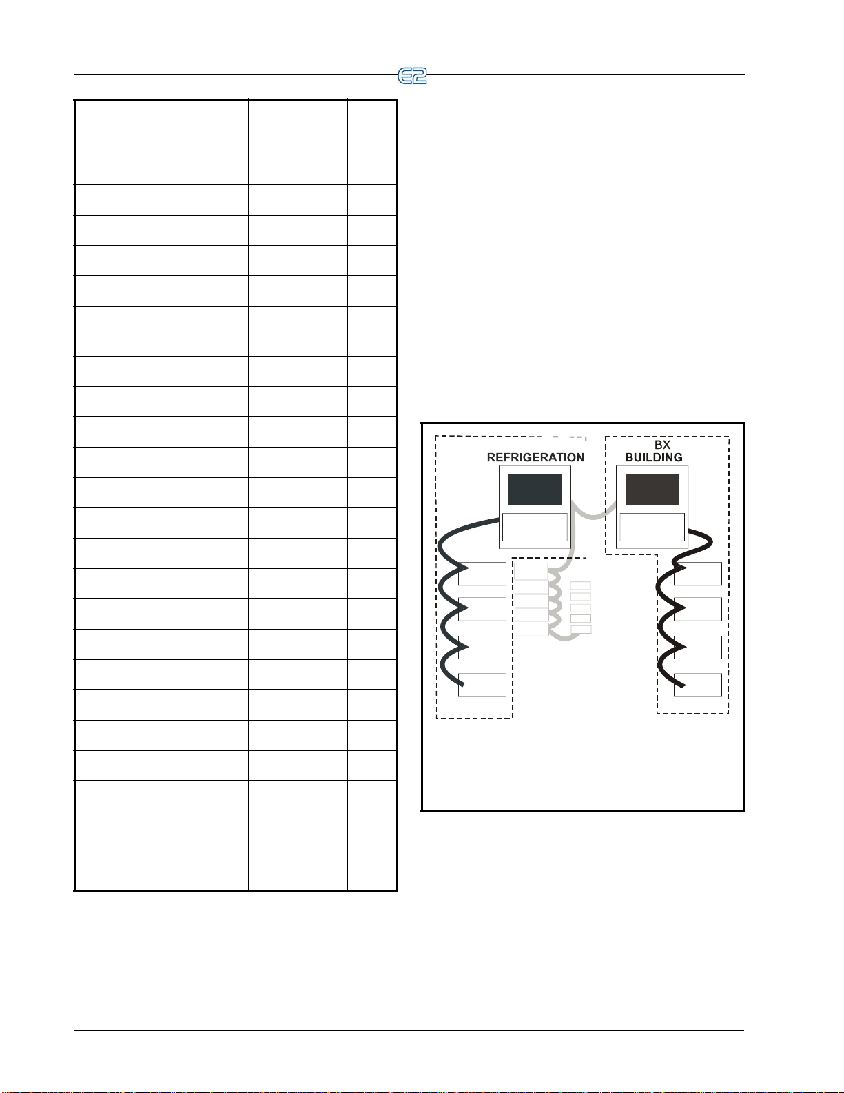
RXE2
E2
E2 RX & BX
RS485 I/O NETWORKS
MultiFlex
I/O
MultiFlex
I/O
MultiFlex
I/O
MultiFlex
I/O
CS-100
CS-100
CC-100
CC-100
CC-100
MultiFlex
I/O
MultiFlex
I/O
MultiFlex
I/O
MultiFlex
I/O
Capabilities
CX-
100
CX-
300
CX-
400
1.4 Networking Overview
1.4.1 E2 I/O Network
ESR8 ESR Control 0 99 99
Flexible Combiner 64 128 128
Heat/Cool Control 4 6 8
Holiday Schedule 8 16 32
HVAC Zone 4 6 12
Infrared Leak Detec-
1 16 16
tion
Irrigation 2 2 2
Lighting Control 6 24 48
K5 Ref Scroll 0 0 31
Logging Group 8 32 32
Loop/Sequence Control 8 16 28
MultiFlex ESR 0 31 31
MRLDS 24 24 24
Most of the general purpose input and output commu-
nications devices required by the E2 to control refrigeration systems are connected to the E2 via the I/O
The I/O Network is a simple RS485 three-wire connection
that allows data interchange between input boards (which
read sensor values and digital closures), output boards
(which carry out commands from E2’s control applications), and the E2 itself.
The I/O Network is the same thing as the COM A and
COM D Net
previous generation of controllers, REFLECS. This allows
current owners of Emerson Retail Solutions’ Refrigeration
Monitor and Control (RMC) or Refrigeration Monitor and
Case Control (RMCC) controllers to easily retrofit with an
E2 RX without need for re-wiring.
works found on Emerson Retail Solutions’
Network.
Performance Alert 0 0 63
Power Monitoring 2 8 16
Pulse Accumulator 4 8 16
RCB/RCB-P Controller 0 32 32
RMS Asset 99 99 99
Standard Circuit 6 12 32
Suction Group 0 0 4
TD Condenser Fan
8 16 28
Control
TD3 Controller 0 99 99
Time Schedule 8 16 32
Table 1-3 - CX-100, CX-300, and CX-400 Comparison
Figure 1-2
Network:
- E2 RX/BX I/O Network Diagram
Figure 1-2 shows the peripherals that make up the I/O
iFlex - The MultiFlex line of control system
• Mult
boards provide a wide variety of input, output, and
smart control solutions, all of which are based on a
single universal hardware platform.
OSMT - Relay output board - activates and deac-
• 8R
tivates up to eight devices.
1-4 • E2 RX/BX/CX I&O Manual 026-1614 Rev 4 5-JAN-2013
Page 21
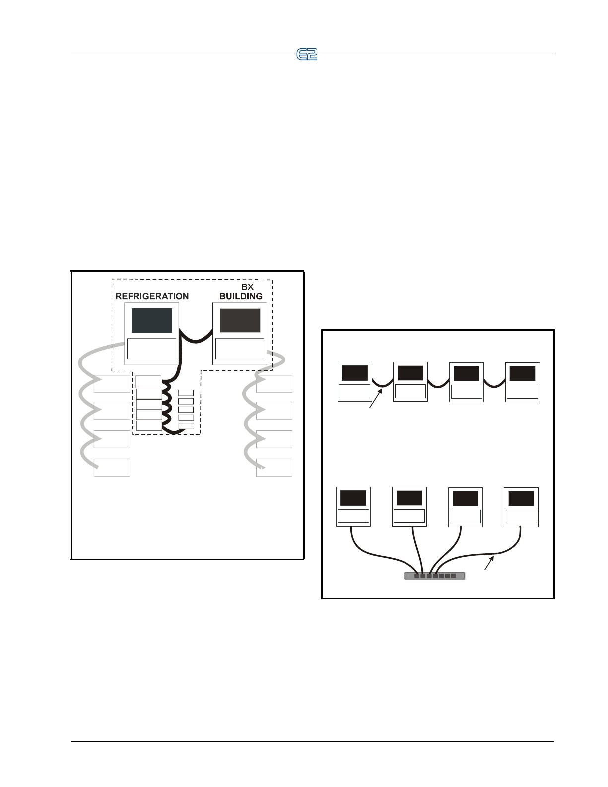
1.4.2 The E2 Echelon Lonworks
RXE2
E2
E2 RX & BX
ECHELON NETWORKS
MultiFlex
I/O
MultiFlex
I/O
MultiFlex
I/O
MultiFlex
I/O
CS-100
CS-100
CC-100
MultiFlex
I/O
MultiFlex
I/O
MultiFlex
I/O
MultiFlex
I/O
CC-100
CC-100
Echelon Box-To-Box
Ethernet Box-To-Box
Switch
CAT5 CABLE
ECHELON CABLE (daisy chain)
Network
The E2 is also compatible with a network platform
called Lonworks. This is most commonly referred to as
“the Echelon Network,” after the company who invented
the platform, the Echelon Corporation.
In general, peripherals with control functions — such
as case
E2 RX and BX units — are interconnected on the Echelon
Network. These controllers do most of their own computation and system control, but they
E2s to provide logging, alarm control, and other functions.
In addition to these, Emerson Retail Solutions also offers
Echelon-compatible input and output boards similar to
those available for the RS485 Network.
controllers, rooftop HVAC controllers, and other
communicate with other
side mounted electronic evaporator pressure regulators (EEPRs).
• TD3 - T
emperature display - has three inputs that
monitor case temperature, product temperature and
defrost status.
d Party Echelon Devices - Echelon® LON-
• Thir
®
MARK
devices communicate with E2 through its
“Open Echelon” networking feature, and require a
license key and a description file that is loaded into
the E2 that enables communication.
1.4.3 Interconnection With Other E2s
In large installations where more than one refrigeration
system is present, or where E2s are controlling both refrigeration and building HVAC sys
E2s share information with each other across either the
Echelon Network or via Ethernet.
tems in the same site, the
Figure 1-3
nicate across the Echelon Network:
Networking Overview Introduction • 1-5
- E2 RX Echelon Network Diagram
Figure 1-3 shows the E2 RX peripherals that commu-
• CC-100 - Case
fans, defrost, and refrigeration for a single case. The
CC-100 controls pulse or stepper valves to provide
precise evaporator control, resulting in better temperature maintenance and energy efficiency.
• ESR8 -
outputs on this board allow the E2 to control circuit
temperature in up to eight circuits using suction-
control board - controls all lights,
Evaporator stepper regulator - the analog
Figure 1-4 - E2 RX/BX Network
Page 22

1.5 Documentation Overview
The E2 RX and BX controllers are among the most
versatile and customizable control system products avail
able on the market. Because of the enhanced capabilities
of the E2s, programming, installation, and operation of E2
and its accompanying peripherals are supported by several
different Emerson Retail Solutions publications. All of the
publications listed below can be ordered by contacting
Emerson Retail Solutions:
• E2 Installation and Operation Manual for RX
Refrigeration, BX HVAC, and CX Convenience
Store Controllers (026-1610) - The manual you are
currently reading. The Installation and Operation
Manual covers hardware installation, network
setup, and important operator functions such as
viewing status screens or logs, and performing
manual defrosts.
The Quick Start section (Section 10) is designed to
guide you quickly through setup of the most simple
and vital refrigeration control applications (such as
suction groups and condensers). More detailed
information is included in the online help.
• Router and Repeater Installation Guide (P/N 026-
1605) - If you have a large site with 64 or more
devices on the Echelon Network, you might require
the use of a router or repeater to properly set up
your Echelon Network. The Router and Repeater
Installation Guide will help you determine when a
router or repeater should be used, how and where to
set it up, and how to configure the E2(s) on the net
work to interact with the router or repeater.
• Emerson Retail Solutions Product Technical
Sheet Binder (P/N 026-1904) - The product sheet
binder gives important installation information
about sensors, transducers, thermostats, and other
essential items that are a part of every Emerson
Retail Solutions control network. The product sheet
binder is not necessary for field installation instruc
tions; however, it may be a useful reference for contractors and OEMs who require more information
about a specific peripheral.
• MultiFlex ESR Installation and Operation Manual (P/N 026-1720) - From general information to
details on mounting, wiring, and heat dissipation,
the MultiFlex ESR manual provides the informa
tion you need to install and operate the MultiFlex
ESR board, in addition to valuable information on
software setup and valve control.
-
• MultiFlex I/O Board Installation and Operation
Manual (P/N 026-1704) - Installation and opera
tion manual for the MultiFlex 16 and all versions of
the MultiFlex combination input/output board,
excluding unit controllers such as the CUB and
-
-
-
RTU.
• MultiFlex CUB/CUB II Condensing Unit Board
Installation and Operation Manual (P/N 026-
1705) - Installation and operation manual for the
MultiFlex CUB (old style) and the MultiFlex CUBII family , which inclu des the CUB-II and CUB-TD.
• MultiFlex RTU Rooftop Controller Installation
and Operation Manual (P/N 026-1706) - Installa
tion and operation guide for the MultiFlex RTU
(replacement for ARTC).
• MultiFlex RCB Rooftop Controller Installation
and Operation Manual (P/N 026-1707) - An
improved version of the MultiFlex RTU, the RCB
has 16 fully configurable analog and digital input
points. The RCB also has four analog outputs for
use in controlling variable speed fans, economizers,
or modulating heating and/or cooling valves. The
RCB also features a more sophisticated HHT inter
face and updated algorithms for controlling heating,
cooling, dehumidification, and air quality. Refer to
this manual for more information on the MultiFlex
RCB Rooftop Controller.
• E2 User’s Manual Supplement for Flexible Combiner Programming (P/N 026-1620) - The Flexible
Combiner application is an advanced I/O control
program used to combine multiple analog and digi
tal input values using programmed equations similar to those used in spreadsheets, and is a new
feature of E2 versions 2.20 and above. Refer to this
manual for more information on the Flexible Com
biner application.
• Facility Status Display (FSD) Installation and
Operation Manual (P/N 026-1400) - The FSD
reports alarm information and more, (such as tem
peratures, occupancy, case status, and setpoints)
and provides a centralized device for store person
nel to review information by communicating with
the E2 via Ethernet connectivity (minimum E2
firmware rev. 2.68F01). Refer to this manual for
more information on the Status Display application.
• Square D Smart Breaker Control Manual (P/N
026-1711) - The Smart Breaker products are
designed to allow the Emerson Retail Solutions
family of site controllers to command control pan
els (minimum E2 firmware rev. 2.71F01). A
breaker panel generally consists of a series of cir
-
-
-
-
-
-
-
-
-
1-6 • E2 RX/BX/CX I&O Manual 026-1614 Rev 4 5-JAN-2013
Page 23

cuit breakers that are flipped from OFF to ON and
from ON to OFF by commands sent from E2
through MODBUS or a Square D Smart Breaker
Gateway board. Refer to this manual for more
information on the Square D Breaker Panel applica
tion.
• Eaton Breaker Control Manual (P/N 026-1709) -
E2 can communicate directly with Eaton's Breaker
Control Bus (BCB) modules. Communication with
the E2 (minimum E2 firmware rev. 2.82) will
enable users to access features such as Time Sched
ules, Enhanced Lighting, and Logging, with the
added capabilities of dial-out on failure and offsite
remote connection, specifically with UltraSite32
and Site Manager to the breaker panel. The Eaton
Breaker Panel controller is a licensed application
available in the E2 300 and 400 model controllers.
Refer to this manual for more information on the
Square D Breaker Panel application.
• Energy Meter Manual (P/N 026-1726) - The
Energy Meter provides a solution for measuring
energy data with a single device. Inputs include
Control Power, CT, and 3-phase voltage. The
Energy Meter supports multiple output options,
including solid state relay contacts, Modbus (with
or without data logging), and pulse. The LCD
screen on the faceplate allows instant output view
ing.
• iPro DAC (P/N 026-1727) - The iPro DAC is a
packaged HVAC control board for use either as a
stand-alone controller or in zone control applica
tions using a Emerson Retail Solutions E2 BX
building control system. The iPro DAC is capable
of controlling heat and cool stages, fans, humidifi
cation and dehumidification devices and economizers using on-board I/O and control algorithms, as
well as monitor and interact with other building
control systems and peripherals (such as smoke
alarms and CO2 sensors).
-
1.6 On-Line Help System
Overview
-
-
The E2 On-Line Help is the primary source frontpanel/interface users will have to consult when seeking
instruction on properties, screens, menus, and trouble
shooting of hardware/software problems. The on-line help
topics are designed to minimize the time the user would
otherwise have to spend searching through the manual to
find information. Press
General Help menu.
To use on-line help from any screen in the E2 front
panel interface, simply press the E2’s permanent Help
+ keys to open the
key. This opens a pop-up window containing either
information about the screen or menu you are currently on,
or information about the input, output, or setpoint you
have highlighted with the cursor (if available). After the
key has been pressed, will open the Gen-
Help
eral Help menu containing Troubleshooting options.
1.7 Software Licensing
Some applications in the E2 are available only when
activated with a unique license key that is obtained
through Emerson Retail Solutions. Software licensing (see
-
Section 10.15, License Management) allows the user to
activate certain features in the E2, such as Web Services
and third-party controllers. Call your Emerson Retail
Solutions sales representative at 770-425-2724 for more
information about software licensing.
-
-
• MRLDS (P/N 026-1307) - Modular Refrigerant
Leak Detection Sensor (MRLDS) continuously
monitors for low levels of refrigerants most com
monly used in commercial refrigeration systems.
The MRLDS communicates with the E2 controller
via MODBUS. The E2 provides an interface while
the MRLDS will provide the leak monitoring func
tionality.
On-Line Help System Overview Introduction • 1-7
-
-
Page 24

Page 25
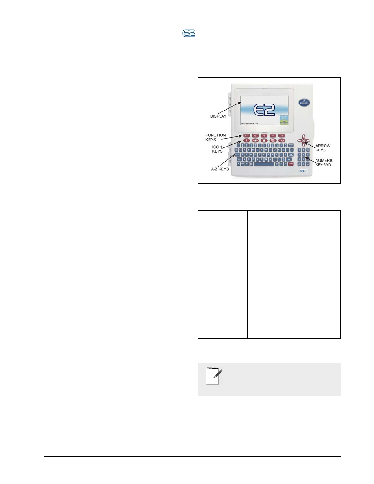
2 Hardware Overview
This section gives an overview of the E2, the hardware, and how it communicates across the I/O and Echelon Networks to control an entire system.
2.1 E2 Hardware
The E2 controller is programmed to monitor and command all aspects of a refrigerati
mental control system. The E2
Network and a LonWorks Network to gather data from
input devices, communicate with other E2s, and activate
or deactivate loads.
In general, an E2 control network will consist of the
llowing components:
fo
1. E2 - The
performs all necessary computations and sends
commands to the output devices that control the
system.
2. In
3. O
utput Boards - Banks of relays, digital pulse
outputs, or analog outputs, which the E2 may use
to control loads.
4. Sma
(for refrigeration) or rooftop controllers (for
building control) that perform control functions
for an individual case or rooftop unit, and send
the data to the E2 for logging and alarm purposes.
5. Modem
if necessary .
6. Networ
other E2s, and all the input, output, and smart
boards.
7. Sensors and
the control network. Sensors “see” what needs to
be controlled on the network, and Loads are what
can be controlled, or more specifically, be turned
on and off, such as compressors, condensers,
lights, and fans.
“brain” of the control network, which
put Boards - Transfer readings to the E2.
rt Boards - Boards such as case controllers
- For remote communication via phone,
k Wiring - Wiring that connects the E2 to
Loads - The “eyes” and “hands” of
on or building environ-
uses both an RS485 I/O
Figure 2-1
Ta ble 2-1 - E2 Specifications
- E2 Front Panel
Dimensions Standard Mount:
9.06” W x 12.06” H x 3.75” D
Recessed Mount:
9.06” W x 10.56” H x 2.0” D
Base:
10.56” W x 10.56” H x 3.75” D
Operating
Temp
Storage Temp -40°F to 158°F (-40°C to 70°C)
Operating
Humidity
Storage
Humidity
Power 24 VAC ±20%, 50/60 Hz, Class 2
VA Load 50
NOTE: Contact Emerson Emerson Retail
Solutions Customer Service at 770-425-2724
r E2 controller part numbers and model de-
fo
scriptions.
-40°F to 149°F (-40°C to 65°C)
5% - 95% RH non-condensing at
90
°F
5% - 100% RH
E2 Hardware Hardware Overview • 2-1
Page 26
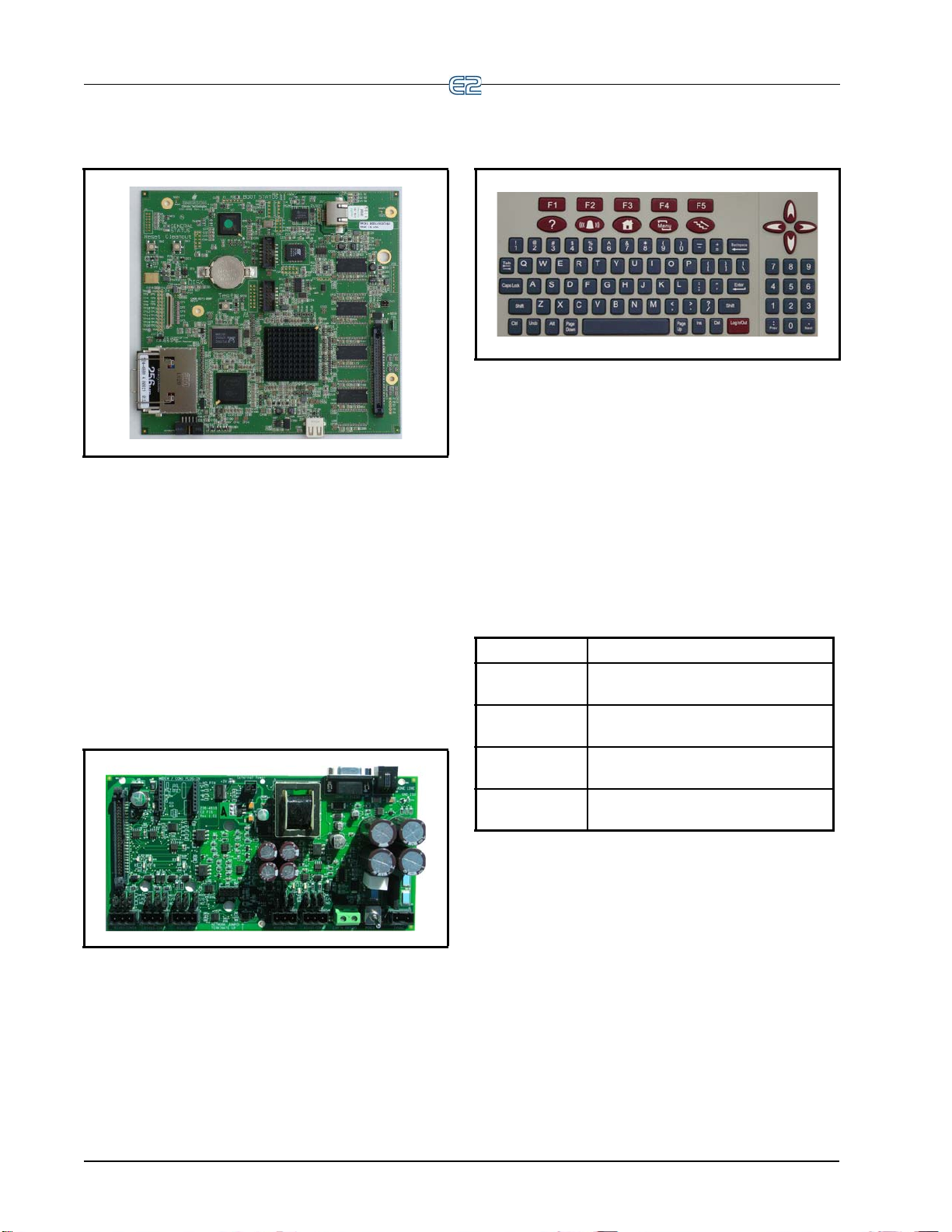
2.1.1 E2 Main Processor Board (CPU)
Figure 2-2 - E2 CPU
The E2 CPU or main processor board (Figure 2-2)
contains the CPU, Ethernet port, and memory used for logging. The coin battery for the E2
and protects log and alarm data during power loss. The
main processor board connects to the PIB via a ribbon
cable. The RX- and CX-100 versions support monochrome display only. For optimum viewing, backlight and
contrast
chrome display depending on the user’s needs.
adjusts are available for customizing the mono-
is located on this board
2.1.2 E2 Processor Interface Board (PIB)
2.1.3 E2 Keypad
Figure 2-4 - E2 Keyboard
The E2 has a QWERTY style keyboard layout with
two rows of function keys. The first row (-) is
comprised of screen-specific function keys, and the second row has designated icon keys. The five icon keys are
Help , Alarms , Ho
Back .
me , Menu , and
2.1.4 LEDs
The PIB, main processor board, and keyboard (located
behind the main board) LEDs can be used to determine the
status of normal operating parameters for the unit.
PIB LEDs Status
Green (14) ON: Power is being applied to the
PI
B
Yellow (RX1) ON: Communication is being re-
ceived on RS485 Port 1A
Yellow (RX2) ON: Communication is being re-
ceived on RS485 Port 1B
Red (TX) ON: Communication is being sent on
RS485
Port 1A and 1B
Ta ble 2-2 -
Figure 2-3 - E2 PIB
The E2 Processor Interface Board (PIB) interfaces the
power and most all communications with the main processor board, and contains all field wiring connections. The
PIB allows you to connect an external
cards, and an external computer. All RS485 connectors are
located on the PIB.
2-2 • E2 RX/BX/CX I&O Manual 026-1614 Rev 4 5-JAN-2013
keyboard, accessory
PIB LED’s Status
Page 27
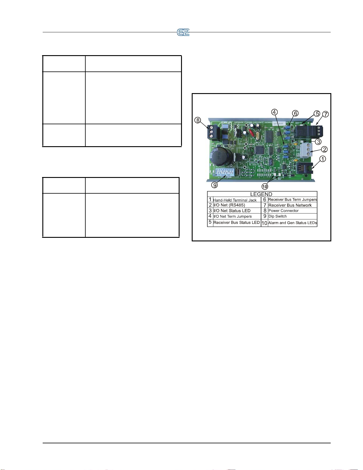
2.2 I/O Network Boards
Main Board
U) LEDs
(CP
Green
(D1 General
St
atus LED for
E2 and Blank
Face E2)
Green
(D18 Boot Status LED)
Ta ble 2-3 - Main Board (CPU) LED’s Status
Keyboard
LED
Green (D5
General St
LED)
1 blink every two seconds (1 second
ON, 1 seco
operating normally.
Solid ON: E2 is booting up.
Faster blinks per second: Indicates an
error con
firmware.
ON: E2 is booting up.
1 blink every two seconds (1 second
ON, 1 seco
atus
mal.
4 blinks per second: A flash and/or
cr
ystal problem has been detected.
Board should be replaced.
Status
nd OFF): Main board is
dition with the hardware or
Status
nd OFF): Status is nor-
and Peripherals
2.2.1 The Gateway Board
Ta ble 2-4
- Keyboard LED’s Status
Figure 2-5 - Gateway Board
The Gateway board is an RS485 to RS485 converter.
One side of the Gateway is always connected to the Emerson Retail Solutions I/O Network. The other side of the
way is the receiver bus (RS485). The receiver bus is
Gate
connected to one or more RS485 devices depending on
which type of Gateway is being used. The Gateway interfaces devices to the Einstein/E2 a
Retail Solutions controller (REFLECS) by simulating
16AI and 8RO boards using Emerson Retail Solutions
standard I/O board protocol. The Gateway can also convert third-party controller protocols to Emerson Retail
ions protocol for custom cells created in the Einstein/
Solut
E2 to interface with third-party controllers (Danfoss,
Woodley, etc.).
The Gateway performs one of two basic functions:
1. It allows control of and/or status of a device using
O board simulation
I/
2. Converts a third-party protocol to Emerson Retail
Solutions
I/O Net protocol and interfaces to a
nd legacy Emerson
I/O Network Boards and Peripherals Hardware Overview • 2-3
Page 28
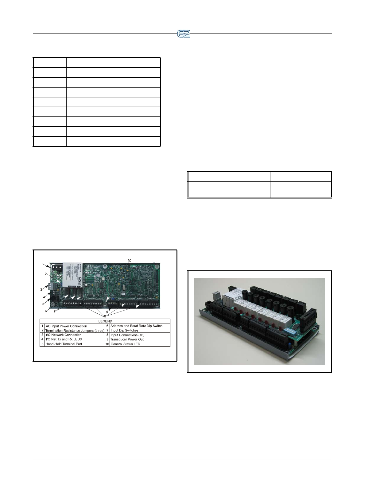
custom cell in Einstein/E2
P/N Gateway Model
810-3500 RF Gate way
810-3700 IRLDS II Gateway
810-3760 RLDS Gateway
810-3710 Danfoss MicroCool Gateway
810-3711 Woodley Case Controller Gateway
810-3712 Woodley Pack Controller Gateway
810-3720 Cutler Hammer Breaker Gateway
810-3721 Square D Breaker Gateway
Ta ble 2-5 - Gateway Board Models
2.2.2 MultiFlex Boards
The MultiFlex line of control system boards provides a
wide variety of input, output, and smart control solutions,
all of which are based on a single universal hardware platform. The board design uses flash-uploadable firmware
ug-in expansion boards to configure the base plat-
and pl
form board and apply it for use
output board, analog output board, or a combination I/O
board.
2.2.2.1 MultiFlex 16 Input Board
as an input board, relay
The MultiFlex 16 is designed to be 100% compatible
th the previous generation of Emerson Retail Solutions
wi
input boards (the 16AI),
troller via an RS485 connection to a REFLECS COM
A&
D Network or an E2 I/O Network. Dip switches on the
board set the network ID (board number) and baud rate.
The board also provides both +5VDC and +12VDC
tput voltage points for use in powering transducers or
ou
other input devices that require power.
The MultiFlex 16 has a Hand-held T
Section 2.2.4, H
may be used by technicians to view the input voltage and
engineering unit values
of a voltmeter or front panel controller display.
Ta ble 2-6 sh ows the part number of the MultiFlex 16.
P/N Model Name Description
810-3013 MultiFlex 16 16 analog/digital in-
Ta ble 2-6
The MultiFlex 16 is designed with several features
th
at make it easy to install, wire, and configure. These
main user interface features are shown in Figure 2-6.
and-held Terminal (P/N 814-3110) that
- MultiFlex 16 Input Board Model
communicates with the site con-
erminal interface
for each input point without need
puts, no outputs
2.2.2.2 MultiFlex Combination Input/ Output Boards
Figure 2-6 - MultiFlex 16 Input Board
The MultiFlex 16 input board offers sixteen combina-
tion analog/digital input points for use by Emerson Retail
lutions E2, Einstein, and REFLECS control systems.
So
The MultiFlex 16 may be used in retrofits with no additional hardware or software setup or upgrades.
2-4 • E2 RX/BX/CX I&O Manual 026-1614 Rev 4 5-JAN-2013
Figure 2-7 - MultiFlex Combination Input/Output Board (Side
View)
Page 29
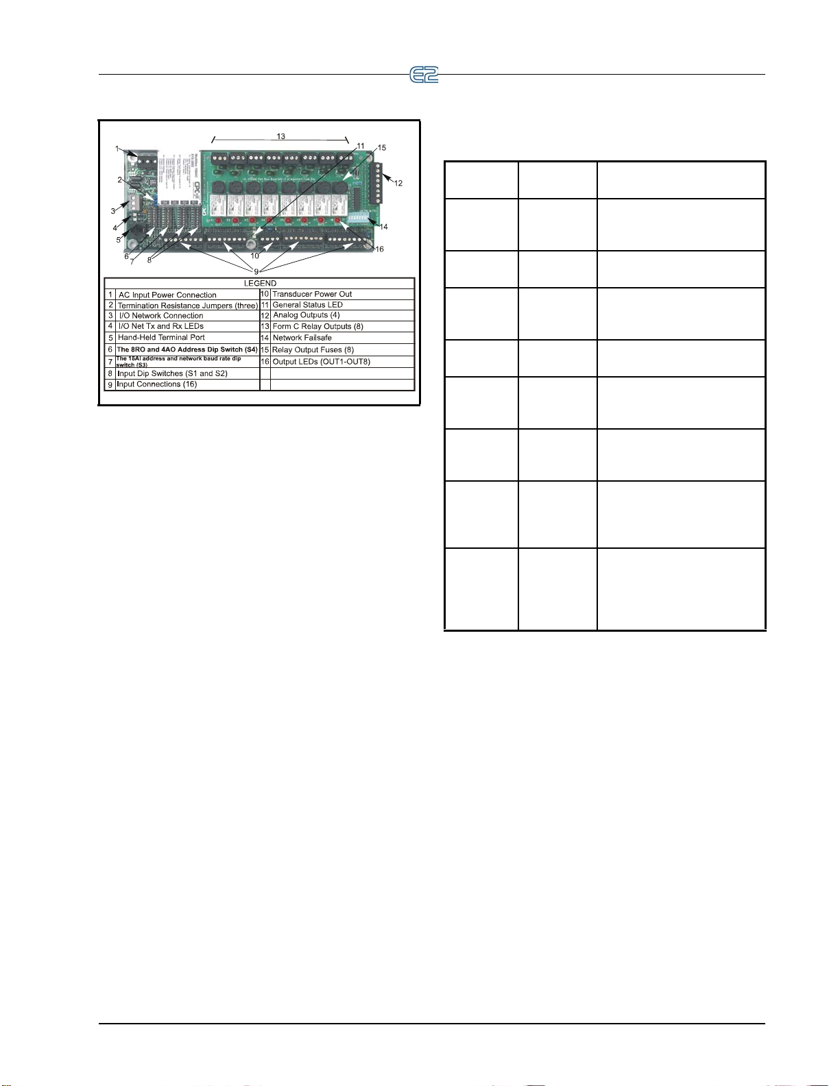
Ta ble 2-7 shows the available models of MultiFlex
combination input/output boards with description and part
mbers.
nu
Figure 2-8 - MultiFlex Combination Input/Output Board (Top
View)
There are several models of the MultiFlex board that
combine the functionalities of input boards, relay output
boards, digital output boards, and analog output boards.
The MultiFlex combination input/output boards are
designed to be replacements for the 8IO Combination
Input/Output Board, but the MultiFlex board provides sev
eral new hardware options and software features.
The MultiFlex combination I/O boards consist of up
combination digital/analog inputs, and a combina-
to 16
tion of relay outputs, digital outputs, and analog outputs.
All boards feature both +5VDC and +12VDC output
tage points for use in powering transducers or other
vol
input devices that require power.
On the RS485 Network, the MultiFlex combination
ut/output boards present themselves to Einstein, E2, or
inp
REFLECS site controllers as 16AI Analog Input Boards,
8RO Relay Output Boards, 8DO Digital Output Boards,
and/or 4AO Analog Output Boards, depending on what
type of inputs or outputs are equipped. Dip switches are
used to assign network ID numbers to each board type.
P/N
Model
Name
810-3063 MultiFlex
AO
88
8 analog/digital inputs, 8 relay outputs, 4 analog out-
Description
puts
810-3064 MultiFlex 888 analog/digital inputs, 8 re-
lay outputs
810-3065 MultiFlex
16
8AO
16 analog/digital inputs, 8
relay outputs, 4 analog outputs
810-3066 MultiFlex
16
8
810-3067 MultiFlex
16
8DO
16 analog/digital inputs, 8
relay outputs.
16 analog/digital inputs, 8
relay outputs, 4 digital outputs
810-3072 MultiFlex
16
16L
16 analog/digital inputs, 16
low-voltage (24VAC rated)
relay outputs
810-3073 MultiFlex
16
16LAO
16 analog/digital inputs, 16
low-voltage (24VAC rated)
relay outputs, and 4 analog
810-3077 MultiFlex
16
16LDO
outputs.
16 analog/digital inputs, 16
low-voltage (24VAC rated)
relay outputs, and 4 pulsewidth modulating digital
outputs
Ta ble 2-7
- MultiFlex Combination Input/Output Board Models
The MultiFlex combination input/output boards also
rt a Hand-held Terminal interface, Section 2.2.4,
suppo
Hand-held Terminal (P/N 814-3110) which allows technicians to view input values, check
relay and analog output
states, and override output points with fixed digital or analog values. For more information on MultiFlex I/O boards,
er to the MultiFlex I/O Board Installation and Opera-
ref
tion Manual (P/N 026-1704).
I/O Network Boards and Peripherals Hardware Overview • 2-5
Page 30
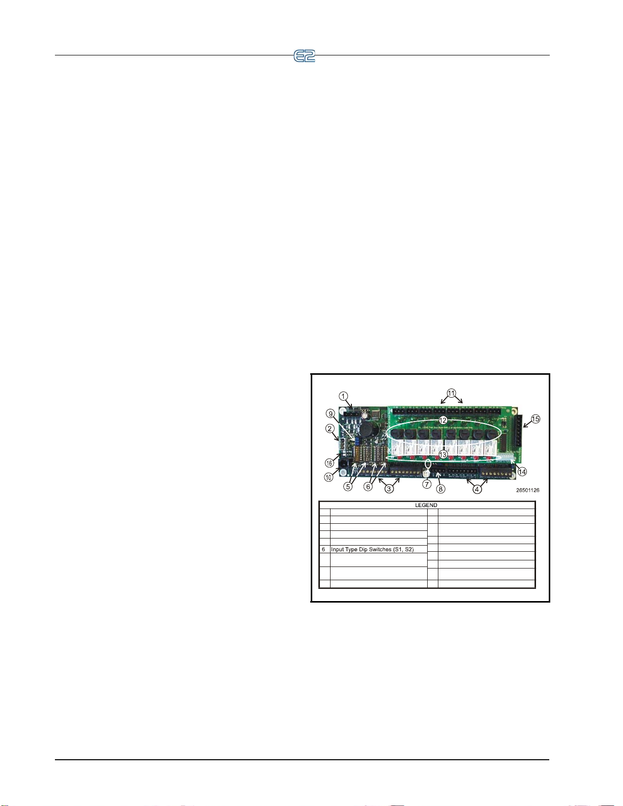
2.2.2.3 MultiFlex CUB
1 Input Power (24VAC)
2 RS485 I/O Network
3 RCB Inputs 1-8
4 RCB Inputs 9-16
5 Network ID Dip Switches (S3, S4)
7 Board Status LEDs
(Code A, Code B, General Status)
12 Relay Output Fuses
(2A Rated, 250V Slow-blow
13 Relay Status LEDs
14 Output Fail-Safe Switches
15 Analog Outputs
8 DC Power Outputs
(3 at +5VDC, 1 at +12VDC)
9 RS485 Termination Jumpers
11 Relay Output Connector
10 Hand-Held Terminal Jack
16 Network Status LEDs
The MultiFlex Condensing Unit Board (CUB) is a
“smart” input/output board designed to control single condensing units. A single condensing unit is a self-contained
pressor and condenser bearing unit which controls
com
refrigeration in a single case line-up or walk-in cooler.
The MultiFlex CUB uses the same general hardware
ration as a MultiFlex 168AO. It is equipped with a
configu
processor and extra memory to allow it to control compressors, condensers, refrigeration, and
defrost for a single
condensing unit using on-board I/O and control algorithms.
The MultiFlex CUB has its own installation and opera-
tion manual, (P/N 026
-1705).
2.2.2.4 MultiFlex RTU (BX and CX Only)
Similar in design to the MultiFlex combination input /
output boards, the MultiFlex RTU board is designed specifically for operating package rooftop
of an E2 BX or REFLECS BCU building control system.
The MultiFlex RTU is designed to be a replacement for the
previous generation ARTC, and is 100% compatible with
all legacy E2 BX and BCU systems.
HVAC units as part
control s
ystem. The MultiFlex RCB is capable of controlling heat and cool stages, fans, humidification and
deh
umidification devices, economizers using on-board I/O
and control algorithms, as well as monitor and interact
with other building control systems and peripherals (such
as smoke alarms and CO
The RCB is an improved version
sensors).
2
of the MultiFlex
RTU. The RCB has sixteen fully configurable analog and
digital input points, whereas the RTU has only eight
inputs, two of which are configurable. The RCB has four
analog outputs for use in controlling variable speed fans,
economizers or modulating heating and/or cooling valves,
whereas the RTU has only two analog outputs for use only
with VS fans and economizers. The RCB also features a
more sophisticated HHT interface and updated algorithms
for controlling heating, cooling, dehumidification, and air
quality.
The MultiFlex RCB-P (pulse control board P/N 81
0-
3076) uses an alternate control strategy that incorporates
logic for controlling heating and cooling functions.
The MultiFlex RCB has its own installation and opera-
tion manual, (P/N 026
-1707).
The MultiFlex RTU board h
relay outputs and 4 analog outputs. Most of these I/O
points are reserved for sensors and input devices required
to read environmental data (such as space and supply air
temperature) and control all output devices that control the
environment (such as heat/cool stages and dampers). Both
auxiliary inputs can be configured for a variety of sensor
types including any type of linear sensor. For linear sensors, the auxiliary inputs can be configured as
By doing this, the minimum and maximum voltage and
minimum and maximum Engineering Unit parameters are
user configurable for these inputs. The RTU relay outputs
are rated for line voltage (240VAC).
The RTU board controls the rooftop unit directly with
lt-in heating, cooling, and humidity control algo-
its bui
rithms. It may operate in stand-alone mode, or it may
interface
ronment in zones and pass along logging and alarm information.
The MultiFlex RTU has its own installation and opera-
tion manual, (P/N 026
2.2.2.5 MultiFlex Rooftop Control Board (RCB) (BX and CX Only)
The MultiFlex Rooftop Control Board (RCB)
(P/N 81
either as a stand-alone controller or in zone control applications using a Emerson Retail Solutions E2 BX building
2-6 • E2 RX/BX/CX I&O Manual 026-1614 Rev 4 5-JAN-2013
0-3062) is a rooftop HVAC control board for use
as 16 analog inputs, 8
Satellites.
with an E2 BX or BCU to control the store envi-
-1706).
Figure 2-9
- MultiFlex RCB
2.2.2.6 MultiFlex PAK Board
The PAK is a distributed pack (rack) controller that
controls compressors and condenser fans. The PAK can
control up to 8 compressor groups containing up to 16
compressors. The compressor control strategy is Fixed
Steps with setpoint/deadband using ON and OFF delays.
Up to 20 Fixed Steps can be configured.
Page 31

The PAK can control up to 4 condenser fan groups
1 Input Power (24VAC)
2 RS485 I/O Network
3 PAK Inputs 1-8
4 PAK Inputs 9-16
5 Network ID Dip Switches (S3)
6 Network Type Dip Switches (S1, S2)
7 Board Status LEDs
(Code A, Code B, General Status)
9 RS485 Termination Jumpers
10 Hand-Held Terminal Jack
11 Relay Output Connectors
12 Relay Output Fuses
(2A Rated, 250V Slow-blow)
13 Relay Status LED
14 Relay Fail-safe Switches
8 DC Power Outputs
(3 at +5VDC, 1 at +12VDC)
15 PAK Analog Outputs 1-4
16 Network Status LED
8
3
7
24VAC CT 75 VAC Power Input
Valve Connectors (8)
I/O Network Input
Termination Jumpers
Network Address Switches
General Status LED
1
5
2
3
4
6
7
8
HHT Jack
TX and RX LEDs
9
10
Open LED (8)
Close LED (8)
9
10
containing up to 8 total condenser fans. The PAK con
denser control strategy is sequential TD control with setpoint/deadband using ON and OFF delays.
The PAK has a compressor/condenser interlock fea-
ture that will override TD control and force the condenser
s to stage off using the TD control OFF delay when all
fan
compressors are off. This feature can be disabled with an
Enable/Disable setpoint or when the discharge pressure is
above a configurable setpoint.
The MultiFlex PAK boards consist of two circuit
boards: a bot
tom layer with 16 combination digital/analog
inputs, and a plug-in top layer which contains a combination of 8 relay outputs and 4 digital DC voltage outputs.
The analog outputs on the Multiflex PAK drive solid
state relays to control the fan stages. The relays control the
pressor groups.
com
The communication interface is RS485 I/O using
the
Standard Extended Address Form for Emerson Retail
Solutions Distributed Controllers. Currently, the PAK is
designed to interface with the Emerson Retail Solutions
E2 controller.
control temperature.
Figure 2-11 - MultiFlex ESR Board Layout
The MultiFlex ESR uses suction side variable-position
evaporator regulators (ESRs) to vary evaporator pressure
for an entire circuit and is an alternative to mechanical
EPR control.
The MultiFlex ESR receives input
data from a Emerson Retail Solutions E2 controller (via the I/O Network)
and then regulates
the stepper valves according to the data
from the E2.
Each MultiFlex ESR board requires a Class 2, 80VA
VAC center-tapped transformer for power. Emerson
24
Retail Solutions transformer (P/N 640-0080) is a multitapped primary transformer that may be used with the
MultiFlex ESR board.
Figure 2-10
2.2.3 The MultiFlex ESR Board
The MultiFlex ESR Valve Regulator board (P/N 810-
3199), shown in Figure 2-11, is an
electronic stepper valve regulator cap
eight stepper motor valves, which are typically used to
I/O Network Boards and Peripherals Hardware Overview • 2-7
- MultiFlex PAK
RS485 I/O Network
able of driving up to
2.2.4 Hand-held Terminal (P/N 814-3110)
The Hand-held Terminal (HHT) is used by manufac-
turers and service technicians to diagnose and test several
Emerson Retail Solutions' existing and legacy products.
of
The HHT can be used on any Emerson Retail Solutions
product with an RJ-11 connector. The most common applications include:
• All MultiFlex I/O boards and the 8ROSMT
• All Gateway boards
• Stand-alone MultiFlex boards (RTU, RCB, PAK,
CUB)
• CCB and CC-100 case controllers
The HHT does not require a separate power source.
The uni
peripheral equipment. The HHT includes a standard male
t is powered from the RJ-11 connector on the
Page 32

RJ-11 to male RJ-11 cable.
LEGEND
Up Arrow - moves to previous screen,
editable field, or top of screen
1
3
4
11
7
8
9
10
2
The power switch determines if the HHT is
in self-powered mode (BATT), ext power (EXT),
or if powered from a target device (HOST)
1
4
3
2
RS-485 Connector
Enter - save into memory
5
6
7
8
10
9
11
12
13
14
LCD - four lines of 16 characters
Numeric keypad
F1 - Home Screen
External Power Connector (9-12 VDC)
Scrolls list selections and scrolls through
ASCII characters if in a text field
5
613
F2- Main Menu
Right Arrow - selects last editable field
starting from bottom of screen; selects
last editable field from bottom to top
Down Arrow - moves to next screen,
editable field, end of screen, or advances
Cancel - clears/erases text in editable field;
cancels overrides
12
14
Left Arrow - selects first editable field from
top of screen, and next editable field from
top to bottom
NOTE: The 9V battery and 9-12V DC adapter
connection are not used on this HHT model
814-3110).
(P/N
troller from the input boards is
checked against current
stored setpoints. If differences in the received input data
and the setpoint information are detected, a signal is either
sent to the proper 8RO relay, or an existing signal is discontinued. Through the use of this relay signal, control
nctions that can be properly maintained by a simple con-
fu
tact closure sequence are effectively
operated by the E2.
The 8RO board is easily installed and operated within
th
e Emerson Retail Solutions Network environment
because of its straightforward design. Several of these features are shown in Figure 2-13.
Figure 2-12
2.2.5 The 8RO and 8ROSMT Relay
- Hand-held Terminal (814-3110)
Boards
The 8RO (P/N 810-3005) board is a general-purpose
board used to connect an E2 to any of eight standard control relay outputs, but is now obsolete and has been
replaced by the 8ROSMT (P/N
T o function, the 8RO bo ard must be connected thr ough
er the Echelon Network or the RS485 I/O Network to
eith
the E2. When properly installed, the 8RO receives an electrical impulse from the E2, which eith
any of eight contact relays. Output definitions within the
E2 allow the user to configure the 8RO board to interact
with any refrigeration system or environmental control
component.
The 8RO board is the direct link between the E2 and
ponent operation. Information gathered by the con-
com
2-8 • E2 RX/BX/CX I&O Manual 026-1614 Rev 4 5-JAN-2013
810-3006) board.
Figure 2-13 - 8RO Relay Output Board
Figure 2-14 - 8ROSMT Relay Output Board
er opens or closes
Page 33

2.2.6 4AO Analog Output Board
4
5
7
8
9
Transmitting (TX ) and Receiving (RX) LEDs
Hand-held Terminal (HHT) Jack
8
9
Alarm and Status Indicator LEDs
4-20mA Channels (2)
Analog Outputs (4)
The 4AO Analog Output Board (P/N 815-3030) (Fig-
ure 2-15) is configured with four analog output connec-
tions that provide a variable voltage signal to any of four
analog devices
4-20mA outputs are provided for channels 1 and 2. The
4-20mA outputs provide a variable current for applications
that are either extern
from the 4AO board.
that may be controlled by a single E2. T wo
ally powered or that require power
Figure 2-16 - 8 DO Digital Output Board
Figure 2-15
- 4AO Analog Output Board (P/N 815-3030)
2.2.7 8DO Digital Output Board and PMAC II Anti-Sweat Controller
For control of anti-sweat heaters, Emerson Retail Solu-
tions supplies the 8DO Digital Output board (P/N 81
0-
3050). The 8DO has eight outputs which may pulse up to
150mA at 12VDC.
Since the 8DO is primarily designed to control anti-
sweat heaters, the 8DO
is the heart of Emerson Retail
Solutions’ Pulse Modulated Anti-Sweat Control (PMAC
II) panel. The PMAC II (P/N 851-1000) provides 16 channels of anti-sweat control circuitry. The PMAC II panel
combines
the 8DO with high-capacity relays in a single
enclosure, providing 256 total amps of anti-sweat heater
operation.
The 8DO is shown in Figure 2-16. The PMAC II is
shown in Figure 2-17.
Figure 2-17 - PMAC II Anti-Sweat Control Panel
I/O Network Boards and Peripherals Hardware Overview • 2-9
Page 34

2.3 Echelon Network Boards and Peripherals
2.3.1 The 16AIe (Discontinued)
Figure 2-18 - 16AIe
The 16AIe (P/N 810-4000) is an Echelon-based input
board similar in function to its I/O Network counterpart,
the MultiFlex 16 (see Section 2.2.2). The 16AIe receives
input signals through any of 16 two-wire connections. The
board receives
wired to any of the 16 input connections located on the
board.
This board has been discontinued and is no longer
available for s
either digital or analog data from sensors
ale.
2.3.2 The 8ROe (Discontinued)
Figure 2-19 - 8ROe
The 8ROe (P/N 810-4010) is an Echelon-based input
board similar in function to its I/O Network counterpart,
the 8RO. The 8ROe board is the direct link between the E2
and component operation. Information gathered by the
controller from the input boards is checked against current
stored setpoints. If differences in the received input data
and the setpoint information are detected, a signal is either
sent to the proper 8ROe relay, or an existing signal is discontinued. Through the use of this relay signal, control
nctions that can be properly maintained by a simple con-
fu
tact closure sequence are effectively
The 8ROe features Form C con
as either normally open or normally closed. Fail-safe dip
switches on the 8ROe allow the installation technician to
specify the desired state of each relay in case of communications loss.
This board has been discontinued and is no longer
available for sale.
operated by the E2.
tacts for wiring outputs
2-10 • E2 RX/BX/CX I&O Manual 026-1614 Rev 4 5-JAN-2013
Page 35

2.3.3 EC-2s
Figure 2-20 - EC-2
The EC-2 is an advanced refrigerated case controller
that doubles as a temperature and case status indicator.
During refrigeration and defrost, the EC-2 controls most
typical case functions, including fans, defrost, and a pulse
valve on the liquid side of the evaporator to regulate superheat.
The EC-2 29x version controls the refrigeration
noid valve to allow the passage of
valve. The EC-2 39x version controls a pulse valve on the
liquid side of the evaporator to regulate Superheat control.
The EC-2 relies on a parent E2 to handle logging,
control, defrost scheduling, and other case control
alarm
functions.
The EC-2 is designed to be mounted on the front of a
refrigerated case. The
temperature with one-tenths of a degree's accuracy. The
display can also show alarm codes to immediately notify
floor managers of alarms and notices. Other lights on the
display show the ON/OFF status of refrigeration, defrost,
and fans.
The EC-2 can be easily programmed using either the
ur front-panel buttons or an optional infrared remote
fo
control. For security, the buttons can be disabled to prevent tampering.
LED display shows the current case
refrigerant to the TXV
sole-
2.3.4 CC-100 Case Controllers and CS-100 Case Circuit Controllers
A CC-100 case control board is a “smart” board capable of controlling all functions for
lights, fans, defrost, anti-sweat, and suction side or liquid
side valve control. CC-100s perform these functions independently from the E2 RX controllers, b
parent E2 for logging, alarming, providing supplemental I/
O values, and coordinating defrost times among circuits.
There are four different models of the CC-100, each of
ich controls a different type of valve.
wh
1. CC
2. CC
3. CS-1
4. CC
The CC-100/CS-100 board is shown in Figure 2-21.
-100P (P/N 810-3160)— Case controller for
liquid-side pulse valves (also called electronic
expansion valves, or EEVs). This model is capable of controlling up to two pulse valves simultaneously (for use in dual-evaporator applications
such as
liquid-side stepper valves (EEVs).
for suction-side stepper valves (also called electronic evaporator pressure regulat
the CC-100 that is used by a particular manufacturer. This board controls temperature in
using suction-side stepper valves that regulate
pressure in the evaporator.
walk-in boxes).
-100LS (P/N 810-3170) — Case controller for
00 (P/N 810-3177) — Case circuit controller
-100H (P/N 810-3171)— A special version of
a single case, including
ut it does rely on a
ors, or EEPRs).
a case
NOTE: There are several variations of the
EC-2. Contact Emerson Ret
800-829-2724 for more information.
Echelon Network Boards and Peripherals Hardware Overview • 2-11
ail Solutions at 1-
Figure 2-21 - Case Controller (CC-100P shown)
Page 36

2.3.5 TD3 Temperature Display
The TD3 is a digital display unit designed to show both
case temperature and product temperature for a refrigerated store case or walk-in freezer. The TD3 mounts on the
front of a case and connects to up
case temperature sensor, a product temperature probe, and
either a defrost termination probe or thermostat). The realtime input values of these probes can be viewed on the
TD3’ s di gital display by pressing the function button on
the front panel to cycle through the temperatures.
The TD3 is connected to a central E2 RX controller via
the Echelo
the TD3 for use in case circuit control.
Figure 2-22
n Network. Input values are sent to the E2 from
A diagram of the TD3 layout is shown in Figure 2-22.
- TD3 Temperature Display Layout
to three input devices (a
2.3.6 Facility Status Display (FSD)
Figure 2-23 - Facility Status Display
The FSD reports alarm information and more, (such as
temperatures, occupancy, case status, and setpoints) and
provides a centralized device for store personnel to review
information by communicating with the E2 via Ethernet
connectivity (minimum E2 firmware rev. 2.68F01).
The FSD has a touch screen color display for quick
igation and can be mounted in a separate, remote loca-
nav
tion from the E2 controller, which
other relevant store information to be viewed from where
it is most convenient for the user.
The FSD can be configured to filter out notices and/or
urn-to-normal alarms, and provides a quick review of
ret
all advisories and detailed advisory information. The FSD
also receives alerts and provides annunciated alarms and
alarm information directly to store and department managers. This compact unit can be installed virtually anywhere
th a standard Ethernet connection and 120V power
wi
source.
If more than one E2 controller is at a site, one E2 must
set up as the alarm annunciator for that site. The FSD
be
will receive alarms from that alarm-annunciator E2 for the
entire site. The FSD will point only to a single E2 at a site
(it will not poll multiple controllers for alarms).
For more information, refer to the FSD Manual
N 026-1400).
(P/
enables alarms and
2-12 • E2 RX/BX/CX I&O Manual 026-1614 Rev 4 5-JAN-2013
Page 37

3 Mounting
9.0"
10.5"
12.0"
3.75"
1.75"
10.5"
This section gives mounting instructions and dimen-
sions for all controllers and peripherals
3.1 Mounting the E2
The E2’s box body style is designed to be mounted
against or inside a wall or panel. If mounted against a surface, the controller will be 3.75” of
If mounted inside a surface, the door and front section of
the back panel will rest 2.0” off the mounting surface. See
Figure 3-1, and Figure 3-2.
3.1.1 Standard Mount
The standard mount is meant for the controller to be
mounted against a wall using the four mounting holes at
the rear of the enclosure shown in Figure 3-3. These holes
are accessible without any removal of
enclosure.
3.1.2 Recessed Mount
in the E2 system.
f the mounting surface.
boards inside the
The recessed mount is meant for the controller to be
bolted against a surface using the eight mounting holes.
The unit may be mounted with the recessed back portion
of the unit inside the wall, and the front portion of the unit
visible through the hole in the wall (Figure 3-1 and Fig-
ure 3-4).
For a recessed mount,
you will need to cut a rectangular hole into the mounting surface 9.0” wide by
(22.86 cm wide by 26.67 cm high). Once this hole is cut,
mount the unit as desired using the eight outer mounting
holes shown in Figure 3-1 and Figure 3-4.
10.5” high
Figure 3-1
- E2 Front and Top Dimensions
Mounting the E2 Mounting • 3-1
Figure 3-2 - E2 Side Dimensions
Page 38

to the cut out (four screws and four nuts are included), but
the plate is equipped with a total of 14 holes for the best
possible fit.
Figure 3-3 - Standard Mount (Inside Rea r of Enclosure)
Figure 3-4 - E2 Recess Mount Hole Locations
3.1.3 Retrofit Mounting
The retrofit mounting plate and bracket allow the E2 to
be mounted where previous generation controllers (Einstein or REFLECS) were. These two options allow conversion of the flush-mounted Einstein and the side-
unted REFLECS.
mo
Figure 3-5 shows the low-profile conversion mount
plate that allows a flush-mounted Einstein to be converted
to a low
the E2 and is attached using the four holes pictured closest
-profile mount. The plate slides over the back of
Figure 3-5 - Conversion Plate for Flush Mount
Figure 3-6 - Conversion Bracket for REFLECS Side Mount
Figure 3-6 shows the conversion bracket that allows a
side-mounted REFLECS to be converted to a side-
ounted E2. The conversion bracket is attached to the
m
back of the E2 using the two holes at the top and bottom of
the bracket, and aligning the oval openings with the oval
cut-outs in the back of the E2 case. Once the E2 is attached
to the conversion bracket, use the two holes in either side
of the conversion bracket (depending on which side is
needed) to mount the E2 to the wall and replace the
REFLECS controller.
3-2 • E2 RX/BX/CX I&O Manual 026-1614 Rev 4 5-JAN-2013
Page 39

3.1.4 Blank Face
Blank face control is designed to be used in a system
with more than one E2. It has no screen or keyboard and is
logged into remotely from another E2 on the Echelon network. The green General Status LED transmits status
information
more information on main board (CPU) status LEDs.
Blank face mounting
dard and recessed mount boxes. See Figure 3-3 and Fig-
ure 3-4.
to the user. See Table 2-3 on page 2-3 for
dimensions are identical to the stan-
3.2 Mounting I/O Boards
The 16AI, 8RO, 8DO, 4AO, 8IO, and MultiFlex
boards are usually installed by the refrigeration or building
equipment manufacturer. Therefore, the installe r need only
make the necessary connections between the E2 and the
cases, condenser boards, and/or HVAC units.
In some instances, an installer may be required to
an I/O board. There are no restrictions on the loca-
mount
tion of these boards; however, for ease of network configuration, it is recommended that the boards be located
adjacent to the E2.
enclosure, but they should be mounted in a location that is
not easily accessible to avoid tampering or damage.
I/O boards may be mounted without an
for the MultiFlex, 16AI, 8RO, and the 8DO.
Figure 3-7
- Single Enclosure Mounting Dimensions
3.2.1 Single/Double Enclosures
The Single enclosure and Double enclosure are supplied with four mounting holes in the rear panel of the
ure. The mounting holes can be accessed without
enclos
removing any of the boards inside the enclosure. Figure 3-
7 shows the dimensions and weight for the Single enclosure. Figure 3-8 shows mounting dimensions for the Double enclosure. When mounting
enclosure, refer to Figure 3-9 for mounting dimensions
boards inside the
Figure 3-8 - Double Enclosure Mounting Dimensions
Mounting I/O Boards Mounting • 3-3
Page 40

3.2.2 Boards Without Enclosures
26501009
3.50"
4.00"
6.00"
4.75"
O 0.218"
TYP 4 PL
4AO BOARD
WEIGHT: 0. 50 LB.
(Snap Track)
16AI, 8RO, 8DO, and Gateway boards not supplied
with an enclosure are supplied with a snap-track for easy
installation. The insulation sheet and I/O board must be
removed from the track before the track is mounted. The
snap-track is mounted using the 0.1875” mounting slots.
Figure 3-10 shows this installation procedure.
Figure 3-9 provides mounting dimensions for the Mul-
tiFlex, 16AI, 8RO, and the 8DO boards. Figure 3-1 1 provides mounting dimensions for the 4AO.
Figure 3-11 - 4AO Mounting Dimensions
The Gateway is typically mounted in the same area as
the site controller, near the controller’s 16AI, 8RO, and
other RS485 Network peripherals. The Gateway is
designed to fit into a standard 3" snap track (supplied with
the board) or may be mounted in a panel or on stand-offs.
Follow the dimensions in Figure 3-12 for panel mounting.
Figure 3-9
Figure 3-10 - 4AO, 8RO, or MultiFlex Snap-Track Installation
- 16AI/8RO/8DO Mounting Dimensions
Figure 3-12
- Gateway Board Mounting Dimensions
The Gateway should be mounted in an environment
with ambient temperature between -40°F and 150°F, with
a non-condensing relative humidity between 5% and 95%.
3-4 • E2 RX/BX/CX I&O Manual 026-1614 Rev 4 5-JAN-2013
Page 41
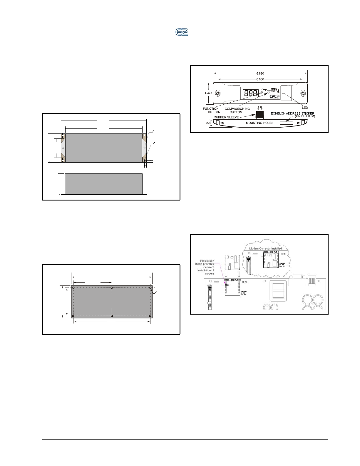
3.3 Echelon Devices
3.00"
2.00"
0.50"
0.50"
8.05"
8.95"
O 0.18“
TYP 2 PLAC ES
26502032
CONTROLLER
(TOP VIEW)
CONTROLLER
(SIDE VIEW)
2.25"
O 0.25"
TYP 2 PLAC ES
0.25"
0.25"
26501055
3.50"
4.00"
10.00"
4.75"
TYP 2 PL
O 0.220"
TYP 6 PL
MULTIFLEX ESR BOARD
9.50"
WEIGHT 9.4 OZ.
3.3.1 CC-100 Case Controller and CS-100 Case Circuit Controller
Generally, the case controller will be mounted within
the raceway or on top of the case. If a controller must be
replaced or installed in the field, it should be located based
on the specific design of the case.
Figure 3-13
3.3.2 MultiFlex ESR
The MultiFlex ESR is supplied with a snap-track. If
the ESR8 is supplied without an enclosure, it is supplied
with 0.500” long metal stand-off dowels that are pressed
into the mounting holes in the board.
- CCB Mounting Dimensions
into the case and connect to the network, the power source,
and the case-mounted probes. Figure 3-15 shows the
mounting dimensions of the TD3.
Figure 3-15 - TD3 Mounting Dimensions
3.4 COM3 Internal
Modem Plug-In Card
(P/N 638-3362)
The E2’s COM3 Plug-In card mounts on the PIB
(Figure 3-16). For more information on the modem/communication expansion card, see Section 4.3.3, COM
Internal Modem Plug-In Card (P/N 638-3362).
3
- COM3 Internal Modem in E2
Figure 3-14
Figure 3-16
- Mounting Dimensions for the MultiFlex ESR
3.3.3 TD3
The TD3 temperature display is almost always
mounted by the OEM as part of the construction of the
refrigerated cases. As such, field installations of TD3s are
rare.
TD3s are typically flush mounted on the front of a
refrigerated
the sales floor. A hole one inch in diameter must be drilled
into the case to allow the TD3’s wiring harness to extend
Echelon Devices Mounting • 3-5
case in such a way as to be fully visible from
Page 42

3.4.1 Two-Channel and FourChannel Repeaters
3.4.1.1 Mounting Repeaters Overview
Repeaters are used to extend the maximum length of a
segment of Echelon cable, or to act as a bridge between
two devices that are farther apart than the cable’s maximum node-to-node distance. Emerson Retail Solutions
fers two versions of repeaters for the E2 controller: an
of
external two-way repeater that comes in an enclosure (P/N
832-1010), and a four-channel repeater mounted in the E2
(P/N 638-4830).
For more information about installing repeaters and
, please refer to the Repeater and Router Installa -
routers
tion and Networking Guide (P/N 02
3.4.1.2 Mounting the Two-Channel Repeater
The external repeater (P/N 832-1010) is externally
mounted within its own enclosure.
6-1605).
3.4.1.3 Mounting the Four-Channel Repeater
The four-channel repeater (P/N 638-4830) serves the
same basic function as the two-channel repeater: boosting
signal strength. However, the four-channel repeater is also
useful as a means of connecting the E2 to its associated
devices using more than one daisy chain.
With a four-channel repeater mounted in the E2, you
can run
field, each of which can be as long as the prescribed Echelon maximum wire length. The fourth channel of the
repeater can be used to connect other E2s
daisy-chain, eliminating the need to run cable from the
field back to the next E2.
th
screws and standoffs to secure the four-channel repeater in
place, and connect the repeater to the PIB with the two-pin
power connector located next to the battery.
as many as three daisy chain segments out into the
in a separate
The standoffs and mounting holes are located above
e PIB in the back of the enclosure box. Use the mounting
NOTE: Because the modem/communication
expansion card and four-channel repeater card
sha
re the same mounting platform, they must
be used separately.
Figure 3-17
For external repeaters, the mounting bracket at the bottom of the enclosure has two 0.156” bolt holes on either
side. U
field as necessary (see Figure 3-17).
When mounting external repeaters, kee
they require a 24VAC Class 2 power source in order to
operate. This will likely require a transformer such as P/N
640-0041 (110V) or P/N 640-0042 (220V) to be mounted
near the external repeater enclosure. Make sure there will
be enough space next to the repeater to mount the transformer.
3-6 • E2 RX/BX/CX I&O Manual 026-1614 Rev 4 5-JAN-2013
- External Repeater Mounting
se the bolt holes to mount these repeaters in the
p in mind that
Figure 3-18
- E2 Repeater Mounting
Page 43

3.5 Sensors and Transducers
3.5.1 Pressure Transducers
Emerson Retail Solutions transducers convert pressure
readings to proportional electrical signals between 0.5 and
4.5 volts. The transducer is designed with a 1/8-inch male
FPT fitting for connection to a standard access fitting. If
the fitting is configured with a Schrader valve, this fitting
will have to be removed and replaced with a 1/8-inch
female fitting. Each pressure transducer is supplied with
20 feet of cable for connection to a 16AI input board.
3.5.1.1 Mounting
The pressure transducers should be mounted in a verti-
cal position (pressure port down) above crank case oil
to prevent drainage of oil into transducer port.
level
3.5.2 Inside Temperature Sensor
3.5.2.1 Location
Inside temperature sensors are supplied within a wallmounted enclosure for attachment to a standard switch
plate.
The temperature sensor should be located in a
location—within the zone to be measured—away from
doors, windows, vents, heaters, and outside walls that
could affect temperature readings. In addition, the sensor
should not be mounted above other sensors that generate
heat during operation (such as relative humidity sensors).
The indoor temperature sensor should be between four
and six feet
from the floor.
3.5.2.2 Mounting
Mount the sensor using the screws provided as shown
in Figure 3-19.
central
Figure 3-19
- Inside Temperature Sensor Mounting
3.5.3 Outside Temperature Sensor
3.5.3.1 Location
The outside or ambient temperature sensor should be
located on the north side of the building, preferably under
an eave to prevent sun-heated air from affecting the temperature of the sensor.
3.5.3.2 Mounting
The temperature sensor may be mounted using any
standard tubing clamp. Emerson Retail Solutions also
offers an aluminum cover and clamp (P/N 303-11 11)
which may be mounted as shown in Figure 3-20 (fasteners
are not provided).
Figure 3-20
Clamp
Sensors and Transducers Mounting • 3-7
- Outside Temperature Sensor with Cover and
Page 44
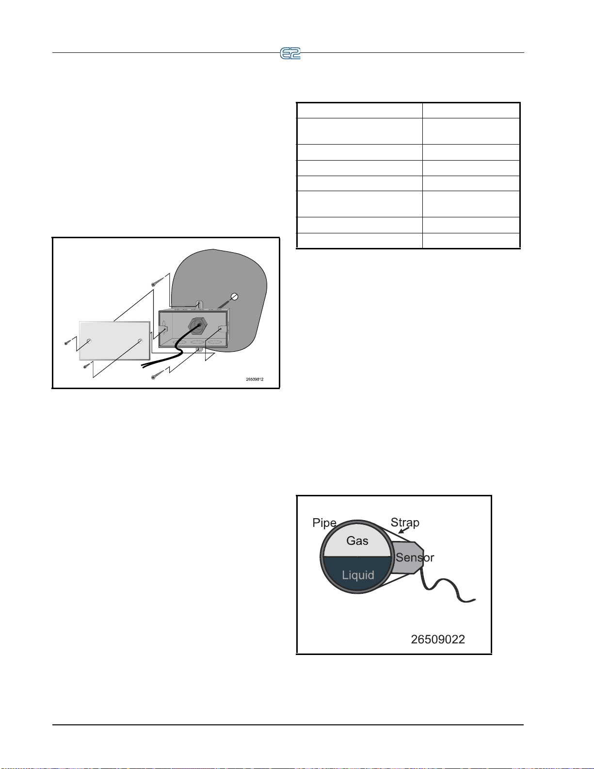
3.5.4 Insertion Temperature Probe
3.5.4.1 Location
The 12-inch insertion temperature probe may be used
to monitor temperature in either the supply or return air
ducts of the AHU or RTU.
3.5.4.2 Mounting
The insertion probe may be mounted in any orientation
within the duct as long as the probe is in the air flow of the
duct. The probe housing should be secured using self-tapping screws. A 0.250” diameter hole is required for the
probe. Figure 3-21 shows the installation of the insertion
probe (self-tapping screws are not provided).
typical sensor applications and the sensor or probe most
suited for
Condenser Outlet (Drop Leg) High Temperature
Liquid (Manifold) Pipe Mount
Suction Temperature Pipe Mount
Discharge Air Bullet
Ambient Temperature (Out-
side)
Condenser Sump Inserti on Probe
Defrost Termination Bullet
that purpose.
Application Sensor Type
Bullet
Bullet
Figure 3-21
- 12-Inch Insertion Probe Mounting
3.5.5 Supply and Return Air Sensors
In addition to the 12-inch insertion temperature probe,
Emerson Retail Solutions uses the same temperature sensor used for outside and inside temperature to monitor
ply and return air temperature.
application, the sensors are supplied without enclosure
covers. The sensors should be mounted directly in the air
stream of the supply or return air duct. The sensors a re no t
supplied with any mounting hardware for this application.
When used in this
sup-
Ta ble 3-1
- Sensor Application and Type
3.5.6.2 Mounting Bullet and Pipe Mount Sensors
Bullet or pipe mount sensors mounted on refrigerant
lines should be secured with a Panduit low temperature
cable tie, number PLT2S-M120, or equivalent. For pipe
mount sensors, the curved surface should be placed
against the pipe and the tie should be positioned in the
groove on the top surface of the sensor. A second tie
should be used to secure the lead to the pipe for additional
support.
Sensors located on refrigerant lines should be insulated
eliminate the influence of the surrounding air. A self-
to
adhering insulation that will not absorb moisture is recommended to prevent ice logging at the sensor location.
The sensor should be positioned on the side of the line
wn in Figure 3-22.
as sho
3.5.6 Refrigeration System Temperature Probes and Sensors
3.5.6.1 Location
Emerson Retail Solutions supplies several temperature
monitoring devices including bullet sensors, pipe mount
sensors, immersion probes, insertion probes, and sensors
for high temperature applications. Each of these sensors is
generally installed on the system by the equipment manufacturer. If a device must be adde
the information supplied with the device and consult the
refrigeration equipment manufacturer. Table 3-1 lists some
3-8 • E2 RX/BX/CX I&O Manual 026-1614 Rev 4 5-JAN-2013
d to the system, refer to
Figure 3-22
- Sensor Orientation
Page 45

3.5.7 Product Temperature Probes
The product temperature probe is designed to be used
alongside food products in a refrigeration case or freezer.
The product probe uses a thermistor type temperature sensor in a sealed, cylindrical contai
oz.). A magnet is contained at the bottom the probe’s
enclosure to allow easy attachment to a side or bottom of a
refrigeration case.
ner (approximately 16
3.5.8 Humidity Sensors and Humidistats
3.5.8.1 Indoor RH Sensor
The indoor relative humidity sensor should be
mounted in a central location within the zone to be measured, away from doors, windows, vents, heaters, and outside walls that could affect te
sensor should be between four and six feet from the floor.
Note that this sensor generates a small amount of heat;
therefore, do not mount temperature sensors directly
above RH sensors.
Mount RH sensor (P/
1. With a flat-head screwdriver, push down the
middle
pop the lid off to expose the circuit board.
2. Insert the flat-head screwdrive
slots on either side of the top of the sensor
case and twist to separate the back plate from
the case.
3. Remove the knock-outs from the back plate
before m
through.
4. Mount the back plate to the wall using the
two
tom of the plate.
5. Replace the cover on top of the back plate by
lin
place.
tab on the top of the sensor case and
open mounting holes on the top and bot-
ing up the tabs, and snap the lid back into
mperature readings. The
N 203-5751) as follows:
r into the two
ounting so wires may be threaded
Figure 3-23
- Indoor RH Mounting Dimensions
3.5.8.2 Outdoor RH Sensors
The outdoor RH sensor (P/N 203-5761)
The outdoor RH sensor (P/N 203-5761) should always
be mounted on the north side of the building if in the
Northern Hemisphere, or on the south side if in the Southern Hemisphere. The sensor should be mounted under an
erhang or otherwise out of direct sunlight (if possible).
ov
Mount the RH sensor (P/N 203
1. Secure the rear side of
side wall using the two mounting brackets, as
n in Figure 3-24. The tub
show
sor element should point straight down.
2. If you will be running the sensor cable through
th
e wall behind the sensor, cut or drill a hole in
the wall through the hole in the enclosure.
-5761) as follows:
the enclosure to the out-
e holding the sen-
Sensors and Transducers Mounting • 3-9
Page 46

Figure 3-24 - Outdoor RH Sensor - Exploded View
3.5.8.3 Duct-mounted Insertion RH Probe
Emerson Retail Solutions specs a duct-mounted relative humidity (RH) sensor (P/
output for use in building control and anti-sweat control
applications using Emerson Retail Solutions input boards.
N 203-5771) with a 0-5VDC
3.5.9 Dewpoint Probe
3.5.9.1 Location
The Dewpoint Probe (P/N 203-1902) should be located
4 to 6 feet from the floor with the probe pointing up. It is
recommended that the Dewpoint Probe be mounted in an
area where it will be exposed only to minimal amounts of
dust.
3.5.9.2 Mounting
Mount the probe using the standard switch cover sup-
plied with the unit as shown in Figure 3-26.
1. Cut a small circular hole in the duct large enough
fo
r the sensor tube to fit through.
2. Bolt the sensor enclosure against the outs
the duct wall so that the sensor element fits
through the hole and into the duct. The enclosure
may be mounted horizontally, as shown in Fig-
ure 3-25 or vertically. The screws should be tight
enough for the foam gasket around the bottom of
the sensor
hole in the duct wall and the outside air.
Figure 3-25
- Duct-mounted RH Sensor - Exploded View
to form an airtight seal between the
ide of
Figure 3-26 - Dewpoint Probe Mounting
.
3.5.10 Light Level Sensor
3.5.10.1 Location
The Light Level Sensor (P/N 206-0002) should be
located facing away from direct sunlight, preferably facing
north in the Northern Hemisphere or south in the Southern
Hemisphere.
3.5.10.2 Mounting
The light level sensor is not supplied with mounting
hardware. The sensor should be mounted horizontally
through the knockout of a standard weather-resistant junction box. Figure 3-27 shows a typical mounting configuration.
3-10 • E2 RX/BX/CX I&O Manual 026-1614 Rev 4 5-JAN-2013
Page 47

Figure 3-27 - Light Level Sensor Typical Mounting
3.5.11 Liquid Level Sensors
Emerson Retail Solutions probe type liquid level sen-
N 207-1000 – discontinued) is usually installed by
sor (P/
the refrigeration and equipment manufacturer. If a replacement sensor must be installed in the field, refer to the
structions supplied with the device, or consult the equip-
in
ment manufacturer.
3.5.12 Refrigerant Leak Detectors
Emerson Retail Solutions supplies the Refrigerant
Leak Detector System as a stand-alone unit that monitors
refrigeration leaks in up to sixteen zones. Consult the
Refrigerant Leak Detector Installation and Operation
Manual (P/N 026-1309) for mounting and installation
instructions.
Sensors and Transducers Mounting • 3-11
Page 48

Page 49

4 E2 Hardware Setup
4.1 Setting up the E2
4.1.1 Enclosure
Figure 4-1 - E2 Inside Enclosure
Open the door and expose the main processor board.
The main processor board and power interface board (PIB)
are mounted side by side, one on each side of the box
enclosure.
Note that the door of the E2 controller
ble with the previous E2 version. The e
not interchangeable.
is not compati-
nclosure doors are
4.1.2 Main Processor Board
Figure 4-2 - E2 Main Board
The main processor board is mounted on the hinged
door part of the enclosure, directly behind the keyboard.
NOTE: E2 enclosure doors are not backwards compatible between E2 units version 3.xx and below and
units that are versi
door with its correct case.
Setting up the E2 E2 Hardware Setup • 4-1
on 4.0 and above. Keep each unit’s
Page 50
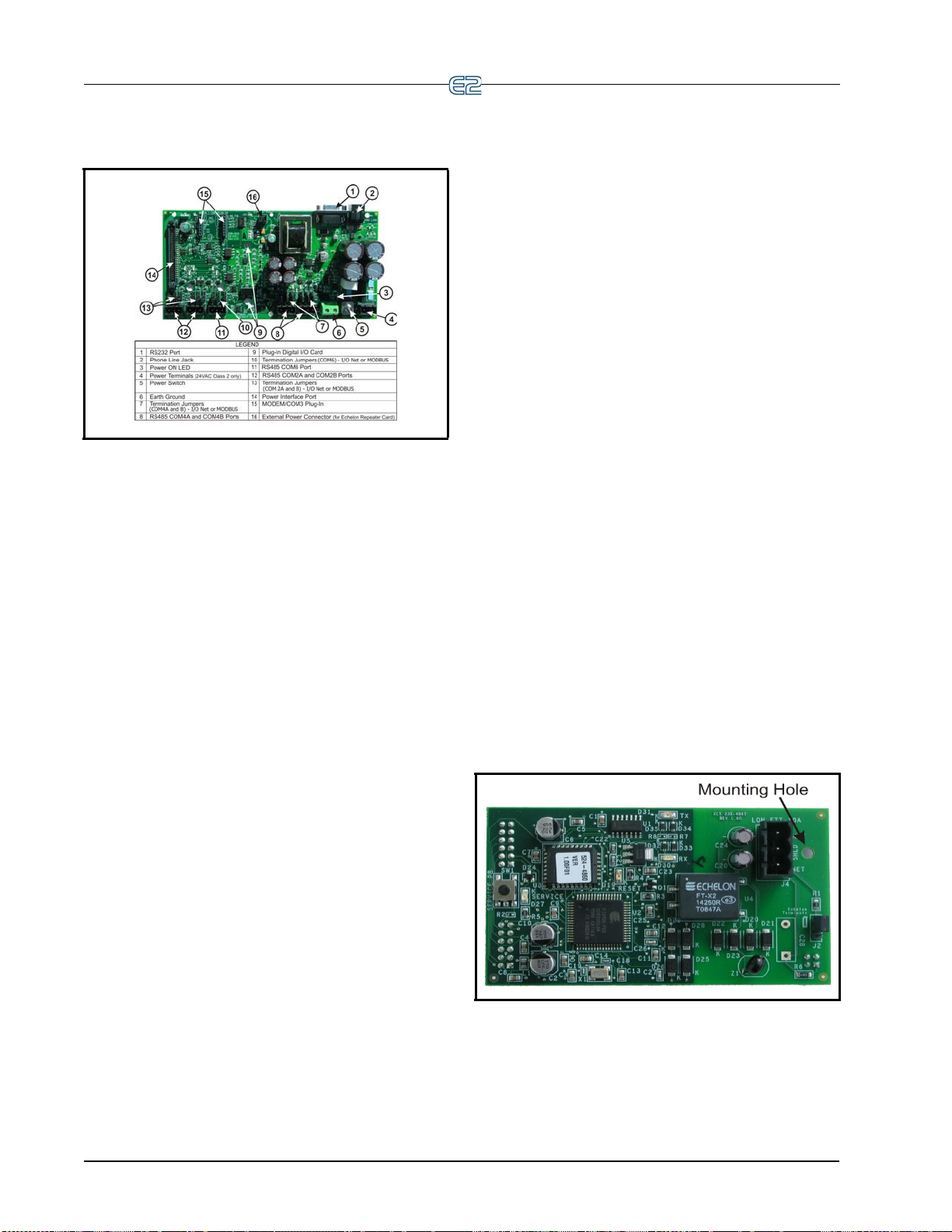
4.1.3 Power Interface Board (PIB)
Figure 4-3 - Power Interface Board
The PIB interfaces the power and most all communications with the main board, and contains all
connections.
field wiring
ld be set to the UP position. For MODBUS, the jump-
shou
ers should all be in the top-most position (MO
Net, the jumpers should be in the middle position (I/O).
For no termination, set the jumpers to the down position
(NO).
D). For I/O
4.2.3 Echelon Network Connect
The next connector is the Echelon Network plug. The
one connector handles both input and output connections.
The input and output cables are connected directly to the
Echelon plug. This plug is the connection to the Case Controller (CC-100), the Evaporator S
(ESR8), TD3s, and other E2s.
tepper Regulator board
4.2.4 Echelon Jumper
There is one Echelon jumper (J2) located on the Echelon board that plugs into the main processo r bo ard.
Additional information about Echelon Networking and
nating the network can be found in Section 8.3, Ech-
termi
elon Network Structuring (Daisy-Chains).
4.2 Powering the E2
Starting at the lower right side of the PIB, the first plug
is the 24VAC input. This must terminate into th e power
supply transformer.
E2 requires 24VAC Class 2 power, which is supplied
by a non-center
Emerson Retail Solutions sup
that may be used to power E2s: one for use with 110VAC
(P/N 640-0041), and one for use with 220VAC (P/N 640-
0042). Both transformers are rated at 50VA, and each will
power one E2 unit.
4.2.1 RS485 Ports
On the lower left side of the PIB are two RS485 Network connector ports. This is where
the case controllers, TD3, ESR8, and Echelon I/O boards)
are connected.
4.2.2 RS485 Termination Jumpers (MODBUS or I/O Net)
There is one set of RS485 jumpers for each RS485 port
(COM2A-2B; COM6; and COM4A-B). Jumpers J8-J10
are located directly above the COM2A connector port, and
jumpers J11-J13 are located directly above the COM2B
port. The RS485 termination jumpers (J8-J22) are used to
terminate the devices at the beginning and end of an
RS485 Network. If the E2 is the beginning of all RS485
I/O or MODBUS Networks, all three of these jumpers
-tapped Class 2 transformer.
plies two transformers
all I/O boards (except
4.3 Add-On E2 Peripherals
The E2 has many plug-in card options to choose from:
• Plug-in Echelon card with mounting screw
• RS485 Modem/communication expansion card
• Plug-in digital I/O Network card
• Plug-in Four-Channel Internal Repeater
4.3.1 Echelon Plug-In Card Kit
(P/N 638-4860)
Figure 4-4 - Echelon Card
Echelon is a two-conductor network that interconnects
E2s and other associated devices. All Echelon devices are
wired together using the daisy-chain method of network
structuring. For the E2 to communicate on the Echelon
4-2 • E2 RX/BX/CX I&O Manual 026-1614 Rev 4 5-JAN-2013
Page 51

Network, the plug-in card must be connected. No Echelon
OUTPUT #1
OUTPUT #2
INPUT #1
INPUT #2
E2 E Power Interface Board (PIB)
COM 1 COM 2
E2 Plug-In
Digital I/O
Network Card
Input and Output Wiring
NORMALLY
OPEN
NORMALLY
CLOSED
Network communication can occur without the card. The
plug-in Echelon card connects to the main processor
board.
4.3.2 COM3 RS232 Plug-In for External Modem (P/N 638-4875)
Figure 4-5 - COM3 External Modem
Modem/com expansion card with an RS232 plug-in
(COM3) that can interface with an external modem, and
an RS485 serial communication port plug-in.
4.3.3 COM3 Internal Modem PlugIn Card (P/N 638-3362)
The plug-in Digital I/O Network card connects to the
interface board to the right of the two fixed RS485
power
I/O Network connectors.
Figure 4-7 - E2 Digital I/O Network Card Install and Wiring
4.3.4.1 LEDs
The plug-in Digital I/O Network card LEDs can be
used to determine the status of normal operating parameters for the card.
Plug-In Digital I/O
Card LEDs
Red D1 (Out 1) ON: Relay Output 1 is On
Red D4 (Out 2) ON: Relay Output 2 is On
Status
Figure 4-6 - COM3 Internal Modem
E2’s Serial Configuration is the centralized location
where all communication ports (COM ports) may be set up
in the E2 controller. To support the increasing number of
third-party devices that E2 can communicate with, E2 has
the expanded flexibility of dynamic COM ports that will
support different types of communication protocols to
meet the specific needs of the user.
4.3.4 Plug-In Digital I/O Network Card (P/N 638-4880)
This card adds two user-programmable digital outputs
and two digital inputs to enable connection of switches
and relays (relay contacts are rated at 3A up to 24 VAC).
Ta ble 4-1
- LED Status for Plug-In Digital I/O Card
4.3.5 Plug-In Four-Channel Internal Repeater
The four-channel repeater (P/N 638-4830) boosts signal strength on Echelon Networks. However, the fourchannel repeater is
the E2 to its associated devices using more than one daisy
chain.
With a four-channel repeater mounted in the E2, you
can run
as many as three daisy chain segments out into the
field, each of which can be as long as the prescribed Echelon maximum wire length. The fourth channel of the
repeater can be used to connect other E2s
daisy-chain, eliminating the need to run cable from the
field back to the next E2.
The plug-in Four Channel Internal R
nects above the power interface board on the case mounts
g standoffs and screws.
usin
See Section 3.4.1.3,
Repeater for more information.
also useful as a means of connecting
in a separate
epeater card con-
Mounting the Four-Channel
Add-On E2 Peripherals E2 Hardware Setup • 4-3
Page 52
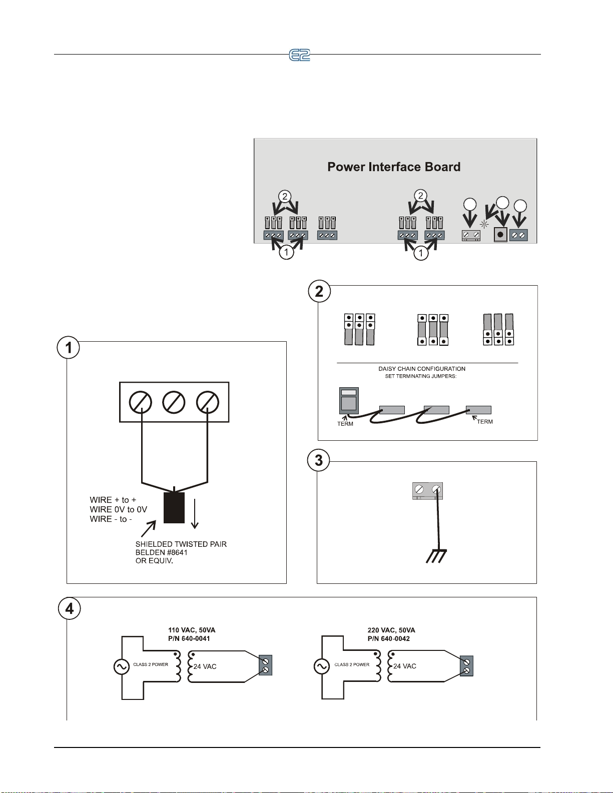
1.Connect the I/O or MODBUS Network to
one or all of the E2 RS485 I/O
or MODBUS Network ports. (A maximum of
31 devices can be wired to each I/O or
MODBUS Network port.)
2. If the E2 is the beginning of all RS-485 I/O
or MODBUS Networks, set all three jumpers
to the UP position. For MODBUS, set the
jumpers in the top-most position (MOD). For
I/O Net, set the jumpers in the middle position
(I/O). For no termination, set the jumpers to
the DOWN position (NO).
3. Connect earth ground to one of the two
ground terminals provided. Use 12 AWG
(preferred) or 14 AWG wire and keep as
short as possible (less than 12 inches
preferred).
4. Connect 24VAC to the power terminals.
5. Flip the power switch to the ON position.
When 24VAC has been applied to the board,
the green LED will illuminate.
E2 INSTALLATION GUIDE
4
3
5
BLACK
SHIELD
WHITE
TO OTHER
RS485
DEVICES
_
0V
+
I/O or MODBUS Network
OBSERVE WIRE
COLOR POLARITY
NOT TERMINATED TERMINATED
FOR I/O NET
RS485 I/O or MODBUS Net
Earth
Ground
Connector
12 or 14 AWG
AC1
AC2
AC1
AC2
24VAC
24VAC
MOD
I/O
NO
MOD
I/O
NO
Can be any COM port on the board
TERMINATED
FOR MODBUS NET
MOD
I/O
NO
[
[
[
[
[
[
[
[
[
4-4 • E2 RX/BX/CX I&O Manual 026-1614 Rev 4 5-JAN-2013
Page 53

5Serial
E2 PIB COM PORT ASSOCIATIONS
COM1
Serial Device
RS232 Port
POWER INTERFACE BOARD
(PIB)
E2 Enclosure (Right Side)
COM2 COM6
COM4
Serial Device
RS485 COM Ports
Plug-In
Modem
Card
COM3
Configuration
5.1 Overview
E2’s Serial Configuration is the centralized location
where all communication ports (COM ports) may be set up
in the E2 controller. To support the increasing number of
third-party devices that E2 can communicate with, E2 has
the expanded flexibility of dynamic COM ports that will
support different types of communication protocols to
meet the specific needs of the user.
Previously, all COM ports were pre-defined to support
specific type of serial device. E2 now has five configu-
a
rable COM ports that can communicate with different
ces on the network.
devi
5.2 COM Ports
The Serial Connection Manager is located in General
Setup under the Serial tab. To access Serial connections to
set up the COM ports, press Alt + M, or from the E2 Main
Menu:
5.3 Serial Device and Software Setup
After the COM card has been connected to the E2, set
up the associated COM port in the Serial Connection Manager:
Figure 5-1 - Serial Configuration Screen
- System Configuration
1.
2.
- System Information
3.
- General Controller Info
4. C3: Serial tab
T o begin, first select the COM port you wish to set up,
se the protocol, and set the baud rate.
choo
The user associates the various hard
the COM ports listed under the Serial tab. Five COM ports
have user-configurable values such as baud rate and connection type settings.
Pre-Sets
COM1 is pre-set for serial connection. COM3 is preset with a modem-only connection type. The COM5 connection is a non-configurable E2 keyboard port.
NOTE: If a COM card is not connected to the
E2, its associated COM port will not be visible
in
the Serial Configuration screen.
ware devices with
Figure 5-2 - Associated Device Connections and COM Ports
Overview Serial Configuration • 5-1
Page 54

COM1
Serial Device
RS232 Port
COM2
Serial Device
RS485 COM Port
(2 Connectors)
Plug-In
Modem
Card(s)
COM3
COM4
COM6
E2COM# ASSOCIATIONS CONNECTOR
COM1 COM1 is a pre-set serial connection type (for a
PC or laptop) and is located on the
RS232 port on the PIB. The baud rate is configurable.
COM2 COM2 may be configured to the type of serial devices you are connecting:
I/O Net 1-3 (default), ISD 1.0, IMC/Prodigy
, or MODBUS 1-3. These devices are
connected via the RS485 connectors (for wiring convenience, two connectors are
available) on the PIB. The connection type and baud rate are configurable.
COM3 COM3 is a pre-set connection type for modems only (optional). The E2 modem/
expansion communication card (P/N 638-3362) has a plug-in modem that uses the
phone line jack (RJ-11). The 638-4875 version has a plug-in for an external modem.
Configure the baud rate and modem type for either the internal modem or the external
modem.
COM4 COM4 ports are located on the PIB board. Configure COM4 to the type of device you
are connecting: I/O Net 1-3, ISD 1.0 (RX unit default), IMC/Prodigy (BX/CX unit
default), or MODBUS 1-3. The connection type is configurable.
COM6 The COM6 port is located on the PIB board. Configure COM6 to the type of device
you are connecting: I/O Net 1-3, ISD 1.0 (RX unit default), IMC/Prodigy (BX/CX
unit default), or MODBUS 1-3. Both connectors cannot be used at the same time.
Configure the connection type, baud rate, and parity.
Ta ble 5-1 - COM Ports with Associated PIB and Card Connections - Refer to Figure 5-2
NOTE: MODBUS and I/O Net can be configured on multiple ports. Duplicate board
numbers cannot be set up on di
fferent I/O Net
connections.
5-2 • E2 RX/BX/CX I&O Manual 026-1614 Rev 4 5-JAN-2013
Page 55

Page 56

Page 57

6 The RS485 Network and Hardware Setup
Previous versions of E2 hardware and firmware before
version 2.30F01 only supported one I/O network port,
with an optional expansion card that could be used for
connection to Copeland ISD compressors or IMC/Prodigy
S-Bus rooftop unit controllers. Beginning with E2 version
2.30F01, E2s now have up to three RS485 network ports,
each of which may be configured as an I/O network, IMC/
Prodigy, ISD, or ECT MODBUS port.
Section 5, Serial Configuration of this manual covers
how to assign COM ports COM2, COM4, and COM6 to
different RS485 network types.
Section 6 (this section)
explains the network types, the hardware that may be connected to each type, and how to configure the devices.
6.1 The I/O Network
All boards and controllers manufactured by Emerson
Retail Solutions for communication with E2 via RS485 are
generally referred to as I/O boards, and the network they
are connected to is referred to as the I/O network
(or I/O Net).
A COM port configured as I/O Net may connect with
up to 127 I/O boards. This network is used by the E2 to
read data from the input boards and to send commands to
the analog and digital output boards. Some unit control
lers, such as CCB case controllers and MultiFlex RCBs,
also communicate with the E2 via the I/O Network.
6.1.1 I/O Board Names and Terminology
There are many input, relay output, analog output, and
combination I/O boards available from Emerson Retail
Solutions for use with the E2. However, separate from the
various MultiFlex unit controller models, E2 only recog
nizes four different types of I/O boards: 16AI, 8RO, 4AO,
and 8DO. All E2-compatible I/O boards communicate
with E2 as if they are one or more of these types of boards.
In this manual and in the E2 interface, when you
encounter these board names, bear in mind that they are
terms that represent many types of boards.
describes all the actual boards or board components for
each E2 “board type.”
Table 6-1
-
-
Board
Max # Translation
Type
16AI 16 Any I/O board that
has digital and analog inputs. The
inputs of a combination I/O board
(8IO or MultiFlex
combo board) are
by themselves
treated as one
16AI.
8RO 31 Any I/O board with
relay outputs. The
relay outputs of a
combination I/O
board (8IO or Mul
tiFlex combo
board) are by
themselves treated
as one 8RO.
4AO 16 Any I/O board with
analog outputs.
The analog outputs of a combination I/O board (8IO
or MultiFlex
combo board) are
by themselves
treated as one
8RO.
8DO 16 Any I/O board with
+12VDC digital
pulse outputs.
ARTC/
RTU
32 Rooftop HVAC
controller board
Boards That Match
Board Type
•16AI (discontinued)
•8IO (discontinued)
•MultiFlex 16
•The inputs on all MultiFlex combo boards
(88, 88AO, 168,
168AO, and 1616)
•All versions of the
Gateway board (some
versions behave like as
multiple 16AIs)
•8RO
•8ROSMT
•The relay outputs on
all MultiFlex combo
boards (88, 88AO,
168, 168AO, and 1616
(which behaves as two
8RO boards)
•8IO (discontinued)
•4AO
•8IO (discontinued)
•The analog outputs on
the MultiFlex 88AO
and 168AO
•8DO (including all
versions of the
PMAC and PMAC
II anti-sweat control
ler)
•Digital outputs on the
MultiFlex 168DO
MultiFlex RTU and
ARTC (discontinued)
-
Ta ble 6-1 - Board Types and Boards Included in Each Type
The I/O Network The RS485 Network and Hardware Setup • 6-1
Page 58

Board
Ty
Max # Translation
pe
RCB 32 MultiFlex RCB
advanced
unit controller
RCB-P 32 MultiFlex RCB-P
(Pulse) advanced
roof
troller
PAK 32 MultiFlex PAK
ra
CCB 99 CCB case control-
lers
ESR 31 MultiFlex ESR
valve controller
CUB-II32 Single condensing
unit controller (one
compressor
to 4 condenser
fans)
rooftop
top unit con-
ck controller
and up
Boards That Match
Board Type
MultiFlex RCB
MultiFlex RCB-P
MultiFlex PAK
CCBs
MultiFlex ESR
MultiFlex CUB II
Ta ble 6-1 - Board Types and Boards Included in Each Type
6.1.2 MultiFlex-Plus (+) Board
6.1.2.2 Board Calculations
With X as the number of plus boards and Y as the number of non-plus boards, use the following equation to
ensure th
at the number of devices on your network has not
exceeded the maximum load limitation of the network. For
example, if the total number of devices is less than 256,
the maximum load limitation has not been exceeded.
X + (Y • 8) < 256
6.1.3 Wiring Types
Emerson Retail Solutions specifies all RS485 I/O and
MODBUS wiring used by the E2 must be Belden 8641
(24A WG, 300V, Emerson Retail Solutions P/N 135-8641);
Belden 8761 (22 AWG, 300V not stoc ked by Emerson
Retail Solutions); or a 600V-shielded 22AWG equivalent
stocked by Emerson Retail Solutions (P/N 135-0600).
These are two-connector shielded twisted pair cables that
support a maximum daisy chain cable distance of 4000
feet (1219 m) between the E2 and the end device on the
network.
The MultiFlex-plus board contains a replacement
RS485 transceiver chip that presents less of a load on the
network than a non-plus board. This increases the maximum number of devices that can be
placed on the network,
but not the number of board types an Einstein controller
can communicate with.
The MultiFlex-plus board now
accounts for only 1/8
the load of a non-plus board with 32 total devices on the
network (one Einstein controller + 31 boards). This new
conversion allows for the placement of 256 devices on the
network (one Einstein controller + 255 boards). The number of boards an Einstein controller can support is
increased
from 31 up to 255 using MultiFlex-plus boards
only. In other words, the number of I/O net devices are no
longer restricted by the I/O net 31-node limitation.
NOTE: The MultiFlex-plus board replaces the
old-style MultiFlex boards and is currently
being shi
pped.
6.1.2.1 Board Designation
Plus boards are always identified with a plus (+) sign
that appears on the plastic insulating cover on the top of
the board, after the board name.
6.1.4 The I/O Network Structure (Daisy Chains)
The RS485 Input/Output (I/O) Network connects all
input and output communication boards together in a single open communications loop
chain,” connects the E2 to multiple input and output communication boards, and terminates
put board on the network. A diagram of this network
arrangem
Figure 6-1
ent is shown in Figure 6-1.
- I/O Network Configurations
. This loop, or “daisy
at the last input or out-
6-2 • E2 RX/BX/CX I&O Manual 026-1614 Rev 4 5-JAN-2013
Page 59

6.1.5 Network Noise Minimization
Site environments will frequentl y hav e nu merous
sources of high EMI, or “noise,” that must be accounted
for when routing RS485 network cable. Although the
cable is shielded against noise,
best practices for minimizing network noise.
In general, installers should follow these guidelines
when installing RS485 networks:
• Avoid running cable next to noise-generating
devices, such as motor starters, contactors, invert
ers, fluorescent light ballasts, arc welders, etc. If
possible, keep cable less than 1 foot away from
noise-generating devices (ideally, at least 5 feet).
• Do not run RS485 cable in the same conduit as
high-voltage wiring, such as 120VAC or 240VAC
power wiring. Keep RS485 cable a minimum of 3
inches away from high-voltage wiring (ideally, at
least 12 inches). If RS485 must cross paths with
high-voltage wiring, cross them perpendicular —
running RS485 and high-voltage wire in parallel
increases the amount of noise induced on the net
work.
• Ensure you are grounding each input device’s 0V
power terminal to a separate earth ground, and set
ting the termination and biasing jumpers as
instructed in
and Biasing Jumpers.
For more instructions on best practices for minimizing
noise, refer to publication 026-1903, E2 Controller Wir
ing Practices, available in the Product Manuals section of
the Emerson Climate Technologies Web site:
www.emersonclimate.com
Section 6.1.8, Setting the Terminating
the installer must follow
-
-
-
6.1.6 Network ID Numbers (Board Numbers)
Each device on an RS485 segment has either a network
dip switch or rotary dials that must be used to assign the
board a unique network ID number.
The network ID number makes a board unique from
other boards on the network of the same ty pe. This allows
E2 to find it and communicate with it easily.
Boards of the same type should be numbered in
sequence, starting with one and continuing with two,
three, and so forth. For example, if a segment contains
four 16AI boards and five 8RO boards, you should num
ber the 16AIs one, two, three, and four; and the 8ROs one,
two, three, four, and five. The same should be done with
multiple 4AO and 8DO boards, and IRLDS leak detection
units.
-
For all boards, except 8IO and 8DO boards, the network dip switch labeled S1 (or S3 for the 16AI board) is
used to set the unique board number of the unit and the
baud rate. The 8IO and 8DO uses rotary dials to set the
board number of the unit.
Numbering the MultiFlex Combination I/O Boards
When it comes to network numbering, the MultiFlex
Combination Input/Output boards (88, 88AO, 168,
168AO, and 168DO) are special cases. They are actually a
combination of three types
boards: the inputs are configured like a 16AI, the relay
outputs are configured like an 8RO, and the analog outputs
are configured like a 4AO.
When a MultiFlex combo board is present on the network, it must be addressed like all three board types.
Therefore, when numbering these boards, you must set a
unique number for both the 16AI, 8RO, and 4AO compo
nents of the board.
Addressing the MultiFlex Boards
For MultiFlex boards, set positions 1 to 5 on S3 for the
16AI component and positions 1 to 5 on S4 for the 8RO
component. Set positions 6 to 8 on S4 for the 4AO or 4DO
segment. For MultiFlex board controllers, use positions 1
to 5 on S3 to set the address.
Addressing the MultiFlex ESR Boards
The MultiFlex ESR uses standard Emerson Retail
Solutions I/O Network addressing. Set positions 1 to 5 on
S1 to set the network ID (address) of the MultiFlex ESR
from 1 to 31.
of Emerson Retail Solutions
6.1.7 Setting the Baud Rate
All I/O boards have dip switches that determine the
baud rate at which they communicate. Currently, the baud
rate dip switch in network components may be set at either
4800, 9600, 19200, and 38400. Setting of the baud rate is
accomplished using dip switches (refer to the board’s
installation sheets at the end of this section for specific dip
switch settings).
Baud Rate for the E2
The baud rate default for E2 is 9600.
Baud Rate for the Gateway
The Gateway can be set to either 9600 baud or 19.2K
baud by dip switch #6. “ON” places the rate at 9600 baud
while “OFF” sets it at 19.2K baud.
Dip switches 6 and 7 control the baud rate at which
the Gateway communicates with the site controller on the
RS485RS485 Network. These switches must be set to the
same baud rate setting as the E2 or REFLECS (usually
9600 baud).
-
The I/O Network The RS485 Network and Hardware Setup • 6-3
Page 60

Dip switch 8 controls the baud rate at which the Gate-
THE TERMINA T I NG JU MP ER S MUST
BE IN THE UP OR I/O POSITION IF AT THE
BEGINNING OR END OF THE NETWORK.
THE TERMINATING JUMPERS MUST
BE IN THE DOWN OR NO POSITION IF NOT AT
THE BEGINNING OR END OF THE NETWORK.
I/O BOARD AND E2 TERMINATING JUMPERS
I/O
NO
I/O
NO
way communicates with the other devices
on the Receiver
Bus Network. This baud rate may only be set to either
9600 baud (switch DOWN) or 19200 baud (switch UP).
All Gateways and receivers on the Receiver Bus Network
must have the same baud rate dip switch setting. It is recommended you use 9600 baud as the Receiver Bus Network baud rate.
Baud Rate for the 8IO, 8DO, and ARTC
There are three I/O devices that do not have baud rates
determined by dip switches. They are as follows:
1. The 8IO -
this board automatically detects the
baud rate being used by the I/O devices on the
network, and adjusts to match their baud rate.
2. Th
e 8DO - this board automatically detects the
baud rate being used by the I/O devices on the
network, and adjusts to match their baud rate.
3. T
he ARTC - this board is fixed at 9600 baud.
Baud Rate for MultiFlex Boards
On all MultiFlex boards, switches 6 and 7 on S3 are
used to set the baud rate. To communicate at 9600 baud,
set switch #6 to the UP position and #7 to DOWN. For
19200 baud, set switch #6 to the DOWN position and #7
to UP.
Baud Rate for the MultiFlex ESR
Set the baud rate on the MultiFlex ESR board by set-
ting switches 6 and 7 on the network address terminal
(labeled S1).
T o communicate at 9600 baud, set switch #6 to the UP
ion, and switch #7 to DOWN. For 19200 baud, set
posit
switch #6 to the DOWN position and switch #7 to UP.
(Currently, 9600 baud is recommended).
Recommended Baud Rate
The baud rate should be set to 9600 baud in all cases.
three jumpers set to the DOWN or NO position.
Figure 6-2 shows the proper terminating jumper settings
for the E2 and for all I/O boards.
Figure 6-2
- I/O Network Te rmination Jumper Settings
6.1.9 Powering the I/O Boards
All models of E2-compatible I/O boards require
24VAC Class 2 input power. Some boards such as the
16AI, 8RO, 4AO, 8DO, MultiFlex ESR, and MultiFlex 16
use a center-tapped power source. All other models, such
as the 8IO and MultiFlex Combination I/O boards, may
use non-center tapped power sources.
6.1.8 Setting the Terminating and Biasing Jumpers
The I/O Network connector, for all I/O boards and the
E2, has a set of three terminating jumpers. They are the
jumpers positioned closest to the I/O Network connector.
The E2 has jumpers next to each of the COM ports that
can be configured as an I/O network (COM2, COM4, and
COM6).
The purpose of the jumpers is to provide network termination resistance and network biasing to the two ends,
termination points, of the daisy chain. One device at the
or
beginning and one device on the end must be terminated
and biased by placing all three jumpers in the UP or I/O
position. All other devices on the daisy chain must have all
6-4 • E2 RX/BX/CX I&O Manual 026-1614 Rev 4 5-JAN-2013
Page 61

Emerson Retail Solutions supplies a wide variety of
2 15VA 1 18VA+ 48VA=
24VAC transformers with varying sizes and either with or
without center taps.
and whether they are center-tapp
Table 6-2 shows the transformer sizes
ed or non-center-tapped.
Table 6-3 lists each board, the board’
or not the board must use center-tapped power.
s rating, and whether
Xformer P/N VA Rating Input Voltage Center Tap?
640-0041 50 VA 110 VAC No
640-0042 50 VA 220 VAC No
640-0056 56 VA Multi-tap (120/208/240 VAC) Yes
640-0050 75 VA 110 VAC No
640-0045 75 VA 220 VAC No
640-0080 80 VA Multi-tap (120/208/240 VAC) Yes
Ta ble 6-2
- Transformers Compatible with I/O Network Boards
Unit Amps VA VAC Center-
tapped?
16AI 0.25 5.0 24 Yes
8RO/SMT 0.75 15.0 24 Yes
4AO 0.5 10.0 24 Yes
8DO 1.5 18 24 Yes
8IO/ARTC 0.75 18 24 No
IRLDS N/A N/A 120/240 N/A
RLDS N/A N/A 120/240 N/A
MultiFlex
ESR
3.3 80 24 Yes
MultiFlex 160.25 6 24 Yes
MultiFlex
8
8, 88AO,
0.75 15 24 No
168, and
168AO
MultiFlex
L,
1616
1.0 20 24 No
1616LAO,
1616LDO
Ta ble 6-3
- Device Power Requirements
To select a power transformer for
a board or a series of
boards:
1. Determine what the total VA is for the boards
that
will be powered by the transformer
(see Table 6-3).
Example: Two MultiFlex 168AOs (15 VA
each), a
nd one 8DO (18 VA) boards are to
be powered by one transformer. The total
VA is:
2. Use a transformer that has a power rating
higher than the total calculated VA
(see Table 6-2).
Example: For boards totalling 48VA, a 56VA trans-
former is sufficient, since 56VA is greater than
48VA.
I/O Board Transformers should be located within 10
feet
of the board it is powering, preferably within the
board enclosure.
6.1.9.1 Wiring Types
For powering I/O boards, use only the listed wire types
from Table 6-4. Three-conductor non-shielded cables are
the recommended wire for connecting between
tapped transformer and the I/O boards. The third conductor should be connected to earth ground. If boards use a
-tapped transformer, also connect the center tap to
center
the earth grounded third conductor.
Power Wiring Types
14 AWG Belden 9495
18 AWG Belden 9493
Ta ble 6-4
- Power Wiring Types
The wire length from the transformer and the number
of boards connected to the same wire determines the type
wire gauge used. In most cases, the distance between the I/
O boards and the transformer that supplies power to them
is not enough to be concerned with. But it is very important not exceed this maximum wire
length or the boards
will malfunction.
the center
The I/O Network The RS485 Network and Hardware Setup • 6-5
Page 62

Use these formulas to determine if the wire gauge you are
using fits within specification:
14 AWG:
Feet = 1920/VA
18 AWG:
Feet = 739/VA
(VA is the total VA rating of the I/O boards)
For example, if you had an 80 VA load:
14 AWG: 24 ft
18 AWG: 9 ft (rounded down)
6.3 MODBUS
E2 controllers version 2.30F01 or greater may select
MODBUS as a network type. The E2 supports connection
to certain MODBUS devices including but not limited to
Control Link CD, Control Link RSC, Control Link ACC,
XR, XM and XEV series controllers.
NOTE: The E2 always acts as the MODBUS
Master. No other MODBUS Master devices
y be on the same network as the E2.
ma
Figure 6-3 - Power Wire Lengths
Sensors requiring 24VAC can be powered from the
same transformer powering
resulting total load of both the input board(s) and the sensor(s) connected to the transformer does not
transformer’s VA rating. Consult Section 6.1.9, Powering
the I/O Boards, and Section 8.6.1, Po
Devices for more information.
the input board as long as the
exceed the
wering Echelon
6.1.10 Board Installation
The following pages give step-by-step graphical
instructions on all steps necessary to install each I/O Network device so that it is powered up and able to communicate with E2. If these devices have not
refer to Section 3.2, M
instructions for these devices.
ounting I/O Boards for mounting
yet been mounted,
6.2 IMC/Prodigy Rooftop Unit Controllers
All E2 Building Controller (BX) versions 2.21F01 and
above may communicate with IMC/Prodigy rooftop units
equipped with IMC/Prodigy control boards version M4-1
or higher. E2 controllers version 2.30F01 and above may
use any of the RS485 I/O ports (COM2, COM4, or
COM6) as a IMC/Prodigy communication port. Version
2.21F01 E2 units may only connect IMC/Prodigys to an
RS485 Expansion Card. Connectivity to IMC/Prodigy is a
licensed feature and must be purchased from Emerson
Retail Solutions.
The IMC/Prodigy interface has
tin explaining installation, network setup, and E2 configuration. Refer to T
echnical Bulletin 026-4117.
its own technical bulle-
6.3.1 Control Techniques Drive (VSD)
Using the MODBUS network type, E2 controllers can
communicate with the Control Techniques variable-speed
drive (VSD). There are three different VSD models the E2
communicates with: Commander SE, Commander SK,
and Unidrive SP drive types.
Note that all CT drives are 2 stop bits, with no parity.
Since ECT MOD
configure the General Services setting for stop bits and
always communicate with the drives using 2 stop bits. The
E2 calculates the difference and adjusts for the additional
stop bit.
Configure the COM port the CT drive will
by pressing Alt + M to open the serial configuration manager. Set the COM port to MODBUS and the bau
(match the baud rate on the CT drive). For more information on setting up serial ports, go to Section 5, Serial
figuration.
The Control Techniques VSD has its own technical
lletin that explains interfacing with E2 (P/N 026-4122).
bu
The installation and operation manual explaining the VSD
is maintained by Control Techniques. Contact your Control Techniques representative for a
BUS specifies 1 stop bit, CT drives will
copy of this manual.
connect to
d rate
Con-
6-6 • E2 RX/BX/CX I&O Manual 026-1614 Rev 4 5-JAN-2013
Page 63
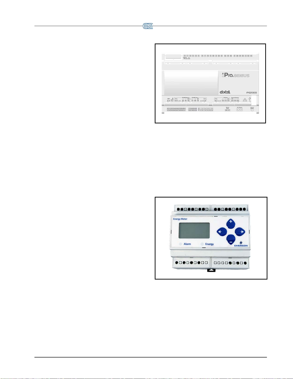
6.3.2 Copeland Discus with CoreSense Diagnostics (ISD)
E2 controllers version 2.21F01 and above may communicate with Copeland ISD compressors using the ECT
MODB
above may use any of the RS485 I/O ports (COM2,
COM4, or COM6) as a Copeland ISD communication
port. Version 2.21F01 E2 units may only con nect Cope land ISD compressors to an RS485 Expansion Card.
Copeland ISD interface
tact your Copeland representative for a copy of this manual.
US network. E2 controllers version 2.30F01 and
The installation and operation manual explaining the
is maintained by Copeland. Con-
6.3.3 XR35CX, XR75CX, and XEV22 Case Controllers
E2 controllers version 2.84 or greater communicate
with the XR and XEV controller. The XR and XEV control compressor regulation, defrost, light, and evaporator
s in refrigeration systems on normal, low, or medium
fan
temperatures, control a wide variety of stepper electronic
expansion valves and anti-sweat heaters (if present), and
measure and regulate the superheat of the refrigerant in the
system.
If the case controller is configured
Clock (RTC), it can be programmed with up to 6 daily
defrosts and an energy saving function. Without the RTC,
the E2 can coordinate defrost cycles and the energy-saving
function.
Several parameters of the Emerson controllers (such as
uts, outputs, setpoints, and alarms) can be configured
inp
directly in E2 and sent to the appropriate Emerson controller, depending on the controller model.
with a Real Time
6.3.4 iPro DAC
Figure 6-4 - iPro DAC
The iPro DAC is a packaged HVAC control board for
use either as a stand-alone controller or in zone control
applications using a Emerson Retail Solutions E2 BX
building control system. The iPro DAC is capable of controlling heat and cool stages, fans, humidification and
umidification devices and economizers using on-board
deh
I/O and control algorithms, as well as monitor and interact
with other building control systems and peripherals (such
as smoke alarms and CO2 sensors).
6.3.5 Energy Meter
6.3.3.1 XR75CX-Case Display
E2 controllers version 4.02 or greater communicate
with the XR75CX-Case Display controller. The XR75CXCase Display is a microprocessor-based controller, suitable for applications on medium or low temperature ventilated refrigeration units. It has up to four (4) analog inputs:
ge air temperature, product temperature, defrost
dischar
temperature and coil out temperature, four (4) relay outputs, and up to two (2) digital inputs. For more information on the XR75CX-Case Display, refer to the XR75CXCase Display manual P/N 02
MODBUS The RS485 Network and Hardware Setup • 6-7
6-1217.
Figure 6-5 - Energy Meter
6.3.5.1 Overview
The Energy Meter provides a solution for measuring
energy data with a single device. Inputs include Control
Power, CT, and 3-phase voltage. The Energy Meter supports multiple output options, including solid state relay
tacts, Modbus (with or without data logging), and
con
pulse. The LCD screen on the faceplate allows instant output viewing.
Page 64

The meter is housed in a plastic enclosure suitable for
installation on T35 DIN rail according to EN50022. The
Energy Meter can be mounted with any orientation over
the entire ambient temperature range, either on a DIN rail
or in a panel. The meter is not sensitive to CT orientation
to reduce installation errors.
6.3.5.2 Supported System Types
The Energy Meter Series has a number of different
possible system wiring configurations. To configure the
meter, set the System Type via the User Interface or Modbus register 130 (if so equipped). The System Type tells
eter which of its current and voltage inputs are valid,
the m
which are to be ignored, and if neutral is connected. Setting the correct System Type prevents unwanted
accumulation on unused inputs, selects the formula to calculate the Theoretical Maximum Sy
mines which phase loss algorithm is
loss algorithm is configured as a percent of the Line-toLine System Voltage (except when in System Type 10)
and also calculates the expected Line to Neutral voltages
for system types that have Neutral (12 & 40).
For more information about this application, see the
gy Meter manual (P/N 026-1726).
Ener
stem Power, and deter-
to be used. The phase
energy
6.3.6 Modular Refrigerant Leak Detection Sensor (MRLDS)
6.3.7 Copeland Discus with CoreSense Protection
Figure 6-7 - Copeland Discus Compressor
The Discus application can monitor semi-hermetic
compressors using the MODBUS network on E2 versions
3.01 and above. The E2 monitors and records semi-hermetic compressor information. The Discus application has
ensive logging capabilities that record a compressor’s
ext
Run History, Fault History, and Alarm Status.
The Copeland Discus is supported on E2 RX-300, CX-
0 and above.
40
Figure 6-6 - MRLDS
The Modular Refrigerant Leak Detection Sensor
(MRLDS) continuously monitors for low levels of refrigerants most commonly used in commercial refrigeratio
systems.
The MRLDS communicates with the E2 controller via
US. The E2 will provides an interface while the
MODB
MRLDS will provide the leak monitoring functionality.
n
6.3.8 Copeland CoreSense Communications
Figure 6-8 - Copeland CoreSense Communications
CoreSense Communications is used on A/C scroll
compressors in the E2. The CoreSense Communications
application provides the user interface requirements for
configuration setup, status display, and alarm handling.
CoreSense monitors information on the compressor's
operation and sends it to the controller, and can also monitor conditions inside the compressor to prevent compres-
6-8 • E2 RX/BX/CX I&O Manual 026-1614 Rev 4 5-JAN-2013
Page 65

sor failures.
Device configuration of the CoreSense Communications can be set at either 9600 or 19200 baud, with either
No parity
, or Even parity.
The Copeland CoreSense Communications is supported on the E2 CX-300, 400, and BX-300, 400.
6.3.9 Light Commercial
•Minimum Damper Position
•Outside Air Temperature
•Inside Humidity
If these inputs are connected
to valid values, they are
sent to the thermostat to be used in place of any locally
connected sensors of the same type. If local sensors are
present and meant to be used, the associated inputs on the
E2 application should be left disconnected.
Thermostat
The thermostat communicates with the E2 using the
MODBUS network. The Light Commercial Communicating Thermostat will enable the
E2 to read status informa-
tion from the device as well as send operational setpoints
the device. The thermostat is available on E2 versions
to
3.02 and above.
6.3.9.1 Thermostat Inputs
The E2 application will provide support for external
real time inputs to the thermostat. These inputs are:
•Zone Temperature
Diagnostic Alarm Descriptions E2 Advisory
6.3.9.2 Advisory and Alarms
The Light Commercial Thermostat also supports diag-
nostic functions. When a diagnostic code is sent to the E2
the thermostat, the E2 application will identify the
from
code and generate the corresponding advisories in the
advisory log.
Diagnostic Alarms
Each of these configurable diagn
can be set to Disabled, Failure, Alarm, or Notice with an
accompanying priority setting.
The diagnostic alarms supported are:
ostic alarms in the E2
Heating Two Hours Thermostat did not see a rise in supply temperature when heating was
called for.
Heat Continuous In heat or backup heat mode, thermostat opens latching relay contacts if
temperature is over 10°F above setpoint.
Te mperature Sensor Fail If heating or cooling is engaged, and either the indoor temperature sensor
reading or the supply air temperature sensor reading starts moving the
opposite way faster than it was before the heating or cooling was engaged,
the thermostat reports a diagnostic message, and shuts down the operation.
Stuck Key A stuck key (closed) has been detected on the thermostat. Stuck Key Detected
Unexpected Temperature
Rise
Cool Eight Hours If cool runs for over 8 hours continuously , the thermostat sets anticipator to
Fan Not Detected If the fan is activated and if the Fan Detect input is enabled, the thermostat
Frost Protection Activated The thermostat allows a frost protection menu option. When enabled, frost
Ta ble 6-5
-Diagnostic Alarm Outputs
Comfort Alert Codes
The thermostat supports the Emerson Climate Technologies Comfort Alert system. On any
Comfort Alert terminal, the thermostat keeps the information on the fault available over the network so that the E2
Thermostat has detected a failure of the internal space temperature se nsor,
or the O/B wiring is incorrect.
zero until call for cool is satisfied.
checks its status 15 seconds after the fan is energized, and if the fan is not
on, it disables any active heat or cool calls, and reports an alarm.
protection is enabled in all system modes including OFF , when temperature
drops below 42°F (5.5°C). All other heat / cool calls are disabled, and
indoor heat is activated until the temperature rises above the frost protection threshold.
can access
this information. On some specific alerts, it will
discontinue compressor operation if active protection is
alert present on
enabled.
The Comfort Alert codes are sent separately from the diagnostic codes. Just like the diagnostic codes, the Comfort
Alert codes are entered as
Heating Problem Detected
Heat Shutdown – Temp too high
Incorrect Sensor Wiring
Failed Sensor or Bad Wiring
Cooling Problem Detected
Proof Fail
Frost Protection
advisories in the E2 advisory
MODBUS The RS485 Network and Hardware Setup • 6-9
Page 66

log.
Comfort Alert Descriptions Cause E2 Advisory
Long Run Time Compressor is running
extremely long run cycles (typi
cally more than 18 hours).
System Pressure
Trip
Short Cycling Compressor is running only
Locked Rotor Locked rotor. Run capacitor has failed.
Open Circuit Compressor open circuit. Outdoor unit power disconnect is open.
Open Start Circuit Compressor current only in run
Open Run Circuit Compressor current only in star t
Discharge or pressure out of
limits or compressor overloaded.
briefly.
circuit.
circuit.
Low refrigerant charge.
-
Evaporator blower is not running.
Evaporator coil is frozen.
Faulty metering device
Condenser coil is dirty
Thermostat is malfunctioning
Compressor Second Stage Cooling Wiring
High head pressure.
Condenser coil poor air circulation (dirty, block ed,
damaged)
Condenser fan is not running
Return air duct has substantial leakage.
Thermostat demand signal is intermittent.
Time delay relay or control board is defective.
If high pressure switch present, check if there is a
System Pressure Trip problem.
Low line voltage (contact utility if voltage at dis-
connect is low).
Excessive liquid refrigerant in compressor.
Compressor bearings have seized.
Compressor circuit breaker or fuse(s) is open.
Compressor contactor has failed open.
High pressure switch is open and requires manual
reset.
Open circuit in compressor supply wiring or con-
nections.
Unusually long compressor protector reset time
due to extreme ambient temperature.
Compressor windings are damaged.
Run capacitor has failed
Open circuit in compressor start wiring or connec-
tions.
Compressor start winding is damaged.
Open circuit in compressor run wiring or connec-
tions.
Compressor run winding is damaged.
Compressor run time is long
System pressure trip
Compressor short cycling
Locked Rotor Trip
Compressor open circuit
Compressor open start circuit
Compressor open run circuit
Ta ble 6-6 -Comfort Alert Outputs
6-10 • E2 RX/BX/CX I&O Manual 026-1614 Rev 4 5-JAN-2013
Page 67

Comfort Alert Descriptions Cause E2 Advisory
Welded Contactor Compressor always runs. • Compressor contactor has failed closed
• Thermostat demand signal is not connected
to module.
Low Voltage Control circuit < 17VAC. • Control circuit transformer is
• Low line voltage (contac
at disconnect is low)
Protector
Ta ble 6-6
Trip Thermostat demand signal Y is
present, but the compressor is
not running.
-Comfort Alert Outputs
The Comfort Alert diagnostic alarms are configurable
• Compressor protector is open.
• Outdoor unit power disconnect is open.
• Compressor circuit breaker or fuse(s) is
open.
• Broken wire or connector is not making
contact.
• High pressure switch open if present in
system.
• Compressor contactor has failed open.
previous readings that can be accessed for analysis.
overloaded
t utility if voltage
in the E2 as Disabled, Failure, Alarm, or Notice with an
accompanying priority setting. All Comfort Alert codes
will share the same advisory type and priority parameters.
High/Low Occ/Unocc Space Temperature Alarms
The thermostat does not provide alarming information
on either high or
low temperatures for the Space tempera-
ture sensor. Therefore, the E2 application will provide this
nctionality.
fu
Supply Sensor Fail Alarm
The thermostat does not provide alarm information on
a failure of the
supply temperature probe (if installed). The
E2 application will provide this functionality. Advisory
type, priority, and delay is provided for the supply sensor
fail advisory.
Conditions for Return to Normal (RTN) on Diag-
nostic Codes
The E2 application will issue an RTN on an active
sory when the corresponding bit of the diagnostic
advi
code goes to zero. If multiple diagnostic advisories are
active simultaneously, they will all return to normal when
the code reads zero.
6.3.10 Refrigerant Leak Detection System (RLDS)
The RLDS provides for the continuous monitoring of
refrigerant gas levels in up to 16 separate test zones or
channels. The instrument is programmed to monitor a
variety of gases and independent leak (small), spill
(medium), and evacuation (large) levels may be designated for each zone. The instrume
nt also retains a log of
Figure 6-9
that are synchronized. These will be read first from the
device. The E2 will be master of all other parameters. An
audible alarm and front panel indicators are provided to
signal alarm and fault conditions, and relay contacts are
provided that can be used to trigger external alarm devices
in the event of a system fault, or if a leak (small), spill
(medium), or evacuation (large) level of gas is detected.
The system also may be fitted with an optional two-channel 4-20mA current loop board for connection to remote
onitoring equipment.
m
- RLDS
The RLDS has alarm level configuration parameters
Welded Contactor
Compressor Low Volt Trip
Protector Trip
MODBUS The RS485 Network and Hardware Setup • 6-11
Page 68

The RLDS features full two-way communications via
an RS485 interface. MODBUS RTU is the communication
protocol standard and can be connected directly to an E2
controller version 3.02 and above. The RLDS is dynami
cally licensed for 15 devices for RX/BX/CX 300-500 and
1 for RX10
0 and CX100 (Same as IRLDS).
-
6.3.10.1 Diagnostic Alarms
Diagnostic Alarm Descriptions
Box Temp Fault Chassis temperature is out of range
Bench Temp Fault Sensor temperature is out of range
Manifold Pressure Fault Pressure readings out of range
RS-485 Fault Communication Error
Loop Fault Current loop is open
Config. Fault No zones are enabled
Zero Filter Fault Charcoal filter needs repl.
Gain Set Fault Gain setting is out of range
A2D Fault A/D converter is not working
Zone Flow Fault No flow during sample cycle
Purge Flow Fault No flow during purge cycle
Over Range Fault Conc. above measurable range
Zero Range Fault Sensor voltage outside limits
Clipping Fault Sensor output voltage too high
Ta ble 6-7 -Diagnostic Alarm Outputs
6.3.11 Copeland Scroll — K5
Refrigeration Compressor
The Copeland Scroll — K5 Refrigeration Compressor
(Lrg Ref Scroll) application can monitor large type compressors using the MODBUS networ k on E2 versi ons 3.02
and abo
Compressor is supported on E2 CX-400, CX-100 and
above. The E2 monitors and records compressor information, configuration setup, status display, and alarm handling. The Copeland Scroll — K5 Refrigeration
Com
the Compressor Association screen. The scroll can be
associated by pressing - Controller Associa-
tions th
ve. The Copeland Scroll — K5 Refrigeration
pressor will be associated with the suction group from
en - Compressor.
Figure 6-10
- Compressor Association screen
6.3.12 XM Series of Case Controllers
The XM series is a set of digitalcase controllers for low
to medium units. The XM series control refrigeration solenoids and defrost (electric or hot gas), evaporator fans,
ghts and have an auxiliary output. These devices are
li
available on E2 version 3.02 and above.
6.3.12.1 XM670
The XM670 is high level microprocessor based controllers for multiplexed cabinets suitable for applications
medium or low temperature. It can be inserted in a
on
LAN of up to 8 different sections which can operate,
depending on the programming, as stand alone controllers
or following the commands coming from the other sections. The XM670 is provided with 6 relay outputs to control the solenoid valve, defrost (which can be either
electrical or hot gas)
auxiliary output and an alarm output. The devices are also
provided with four probe inputs, one for temperature control, one to control the defrost end temperature of the
evaporator
used for application with virtual probe or for inlet/outlet
air temperature measurement. Finally, the XM670 is
equipped with the three digital inputs (free contact) and
are fully configurable.
, the third for the display, and the fourth can be
6.3.12.2 XM679
The XM679 is similar to the XM670, but with one
relay output to drive pulsed electronic expansion valves.
The XM679 also contains two probes that are dedicated
for superheat measurement and regulation.
the evaporator fans, the lights, an
6.3.12.3 XM678
The XM678 is similar to the XM670, but with one
stepper valve output to drive an electronic expansion
valve. The XM678 also contains two probes that are dedicated for superheat measurement and regulation.
6-12 • E2 RX/BX/CX I&O Manual 026-1614 Rev 4 5-JAN-2013
Page 69

6.4 BACnet
BACnet is a communications protocol for building
automation and control networks available for E2 versions
4.02 and above. Any of the three serial ports (COM2,
COM4, and COM6) can be used to communicate with
devices over BACnet. E2 supports BACnet devices that
communicate using MS/TP and IP.
6.4.1 BACnet Overview
BACnet is defined by three basic concepts:
• Object
tors, and other functional elements that make up a
BACnet device. The
specified by BACnet protocol. Analog Input object
and Analog Output object are two of the most commonly used objects. BACnet devices are defined on
the network as
• Obje
ties required by BACnet p
monly used property is Present Value. Other
common properties include
flags. Optional properties for objects such as analog
input include minimum and maximum range, high
and low limits, etc.
• Services –
BACnet protocol defines “services”. These include
object access services, alarm and event services,
file access services, and a few more. Object access
services are the most commonly used since these
provide the fundamental “read/write” access to
object properties.
Data inside a BACnet device is organized as a series of
objects. Each objec
There is always at least one object in a device – it is used
to represent the device itself. This is called the Device
Object. The other objects represent the device’s data.
- The general reference to sensors, actua-
objects fall into categories
a collection of “objects”.
ct Property – Each object has several proper-
rotocol. The most com-
reliability and status
Along with the definition of objects,
t has a type and a set of properties.
Figure 6-11
- BACnet Objects
6.4.2 BACnet Communication
BACnet supports MS/TP or IP based communication.
6.4.2.1 Master Slave Token Passing
Master Slave Token Passing or MS/TP is the protocol
used over RS-485 for BACnet. Each device on the link is
considered the “master” when it has the token. If it does
not have immediate need to use the token, it is required to
pass the token along to the next device. All devices on the
link that do not currently have the token are regarded as
slaves, and are expected to listen to any messages the current master may have for it. Because some devices take
rns being master, the link is effectively peer to peer (not
tu
all MS/TP devices can be master).
It is possible for a device to be a constant slave, though
is uncommon, because in this case a device cannot send
it
such request as I-Am, notifications, etc.
MS/TP devices differentiate themselves with a MAC
address. MAC addresses
device and must be unique on the MS/TP line.
It should be noted that MS/TP BACnet devices do not
use their unique identifier for access
second identifier called a Device ID is used. This is
because BACnet traffic can be routed across IP or MS/TP
(i.e., the physical layer is different). The Device ID has a
much larger addressable range.
MS/TP requires only the baud rate
consistent. All other line disciplines are specified by the
standard and are therefore not configurable. MS/TP also
requires that the E2 to have a MAC address. This is configurable per MS/TP route (serial port).
are unique identifiers set per
ing them. Instead, a
to be specified and
BACnet The RS485 Network and Hardware Setup • 6-13
Page 70

6.4.2.2 BACnet IP (Internet Protocol)
The E2 also supports connecting to devices through IP
(Internet Protocol). The device ID is used to identify the
devices.
6.4.2.3 Discovery
BACnet supports discovery of the devices on a network and interrogation of the devices so they report what
data objects they contain and what properties ea
supports.
ch object
6.4.2.4 Client-Server
To describe which role the device plays during communication we will use the term: client-s
is the side that actively initiates the request. The server is
the side that passively responds to the client reply. BACnet
devices can act both as client and server.
Most simple MS/TP and IP devices are passive servers. They wait passively for a system
and only then do the devices respond. The E2 will mostly
be an active client (although it does have to support some
server aspects).
erver. The client
to poll them for data
6.4.3 MS/TP Network Connection to E2
Before setting up a BACnet, the port on the E2 that has
the MODBUS cable connected must be set up as a MODBUS port.
1. Log in to the E2
2. Press
3. Press
4. This screen will have a “Connection” field for all
5. Input the MAC address in the MSTP M
6. Under the BACne
followed by - General
Controller Info.
+ to open the Serial tab of the Gen-
eral Controller Info setup screens.
COM po
and choose which route it represents such as
“BACnet MSTP-1”.
that the E2 will use for the COM port connection.
changed on the device object.
rts on the E2. Highlight the COM port
with Level 4 access.
AC field
t tab, several parameters can be
Figure 6-12
- BACnet Tab
•Object ID - This is the ID used by the E2 when
participating on a BACnet network. The E2 supports only the Device Object.
ax Master - This is the highest number of
•M
MS/TP MAC addresses that will be searched for
on an MS/TP network. This number must be
higher than the controller with the highest MS/TP
MAC address. Lowering this number will
improve throughput of data from the E2.
DPU timeout - This is the length of time that
•A
the E2 will wait for a response from a controller.
PU retries - This is the number of times the
•AD
E2 will attempt to communicate to a controller
before attempting another message.
6.4.3.1 Add and Connect a BACnet Device
To enable communications between E2 and the BAC-
net, the devices must be added and addressed in E2.
1. Log in to the E2 with Level 4
2. Press
3. On the Th
To commission the device:
- Connected I/O Boards
and Controllers.
ird Party tab, enter the number of
BACnet devices in the BACnet number field.
access.
4. Press
6-14 • E2 RX/BX/CX I&O Manual 026-1614 Rev 4 5-JAN-2013
to return to the Network Setup
menu, then select
- Network Summary.
Page 71

5. Locate the device you added to the network list
and to scroll through the list) and
(press
highlight with the cursor. Press
missioning.
for Com-
Figure 6-13
If there is more than one route, select which route the
device is on. The route may be MS/TP or IP.
6. If this is the first commission after a reboot of the
7. The E2 will present a list of
8. The same list will appear for subsequent commis-
A rescan is needed if a new BACnet device is con-
nected on the route. Initiate the scan by pressing
Rescan.
- Commissioning Screen
E2 (or
a new BACnet route is created), the E2
will display a “search dialog” showing the E2 is
searching for BACnet devices on that route.
device IDs for a set
of devices found during the scan when the search
is complete. Choose which device (and subsequent device ID) to associate with
net application.
sioning to associate new devices quickly.
that E2 BAC-
-
BACnet The RS485 Network and Hardware Setup • 6-15
Page 72

6-16 • E2 RX/BX/CX I&O Manual 026-1614 Rev 4 5-JAN-2013
Page 73
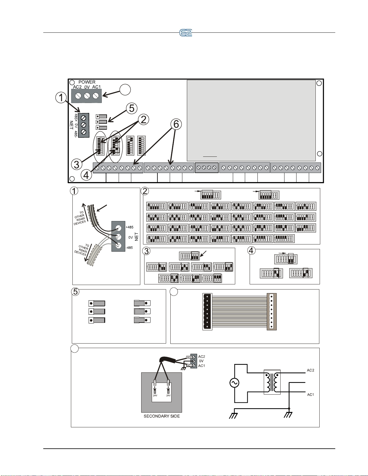
0v SIG
INPUT 1
0v SIG
INPUT 11
0v SIG
INPUT 10
0v SIG
INPUT 12
0v SIG
INPUT 13
0v SIG
INPUT 2
0v SIG
INPUT 15
0v SIG
INPUT 16
0v SIG
INPUT 14
0v SIG
INPUT 3
0v SIG
INPUT 4
0v SIG
INPUT 7
0v SIG
INPUT 5
0v SIG
INPUT 6
0v SIG
INPUT 9
0v SIG
INPUT 8
S2
2345678
1
ON
S1
2345678
1
ON
S4
2345678
1
ON
S3
2345678
1
ON
+
1
2
V
+
5
V
+
5
V
+
5
V
MULTIFLEX BOARD
MULTIFLEX COMBINATION I/O BOARD
INSTALLATION GUIDE
7
1.
2. Set the network address on the first five rockers of dip switch
S3 for the 16AI, and S4 for the 8RO sections of the MultiFlex.
3. Set the network address on rockers 6-8 on S4 for the
4AO or 8DO sections of the MultiFlex if applicable (88AO
and 168AO have a 4AO section). The 168DO has an
8DO section.
4. Set the network baud rate using rockers 6 and 7 of dip
switch S3. For 9600 baud, set #6 UP and #7 DOWN.
For 19200 baud, set #6 DOWN and #7 UP.
5. Set RS485 termination jumpers OUT (term) if at either end
of a daisy chain. Otherwise, set jumpers IN (no term).
6.
Connect board to the RS485 I/O Network.
If replacing an old 8IO or 16AI, use MultiFlex input
adapters (P/N 335-2301) to plug input connectors from old board
into the MultiFlex input sockets. One for inputs 1-4,
and one for inputs 5-8. Otherwise, polarity-sensitive inputs
will have to be rewired. (No adapter is needed for inputs 9-16.)
7. Connect board to power transformer.
If a center tap is
present, use the center tap! Instead, con nect 0V
terminal to a separate Earth ground.
DO NOT
NO TERMINATION
TERMINATION
OUT
IN
J
P2
J
P4
J
P3
J
P2
J
P4
JP3
PLUG INPUT
CONNECTOR
FROM 16AI
INTO THIS
END
#1
#2
#3
#4
#4
#3
#2
#1
PLUG CABLE
CONNECTOR
INTO
MULTIFLEX 16
INPUT SOCKET
MULTIFLEX INPUT ADAPTER
P/N 335-2301
6
YELLOW
YELLOW
0V
24 VAC
24 VAC
120/208/240 VAC
•
P/N 640-0041, 120VAC Primary,
50VA
•
P/N 640-0050, 120VAC Primary,
75VA
•
P/N 640-0042, 220VAC Primary,
50VA
•
P/N 640-0056, Multi-tap
120/208/240VAC Primary, 56VA
•
P/N 640-0080, Multi-tap
120/208/240VAC Primary, 80VA
Note: Please refer to transformer
for primary side wiring.
Acceptable CPC Transformers:
2345678
1ON2345678
1ON2345678
1ON2345678
1
ON
2345678
1
ON
2345678
1
ON
2345678
1
ON
2345678
1
ON
2345678
1ON2345678
1ON2345678
1ON2345678
1
ON
2345678
1
ON
2345678
1
ON
2345678
1
ON
2345678
1
ON
BOARD 1
BOARD 2
BOARD 3
BOARD 4
BOARD 5
BOARD 6
BOARD 7
BOARD 8
BOARD 9
BOARD 10
BOARD 11
BOARD 12
BOARD 13
BOARD 14
BOARD 15
BOARD 16
2345678
1
ON
2345678
1
ON
2345678
1
ON
2345678
1
ON
BOARD 17 BOARD 18
BOARD 19
BOARD 20
23456
7
8
1
S3: INPUT (16AI)
ADDRESS
2345678
1
S4: RELAY (8RO)
ADDRESS
2345678
1ON2345678
1ON2345678
1
ON
BOARD 21
BOARD 22
BOARD 23
2345678
1
ON
2345678
1
ON
2345678
1
ON
2345678
1
ON
2345678
1
ON
2345678
1
ON
BOARD 24
BOARD 25 BOARD 26
BOARD 27
BOARD 28
BOARD 29
2345678
1ON2345678
1
ON
BOARD 30
BOARD 31
2345678
1
S3: BAUD RATE
234567812345678
1
19200 BAUD
9600 BAUD
2345678
1
2345678
1
ON
2345678
1
ON
2345678
1
ON
BOARD 1 BOARD 2 BOARD 3
2345678
1
ON
2345678
1
ON
2345678
1
ON
BOARD 4
BOARD 5 BOARD 6
2345
678
1
ON
BOARD 7
S4: ANALOG (4AO) ADDRESS
(or 8DO ADDRESS OF THE
168DO BOARD)
SHIELDED TWISTED PAIR
BELDEN #8761. FOR PLENUM,
USE BELDEN #82761 OR #88761
OR EQUIV.
WIRE + to + (same color)
WIRE 0V to 0V
WIRE - to - (same color)
7
BACnet The RS485 Network and Hardware Setup • 6-17
Page 74
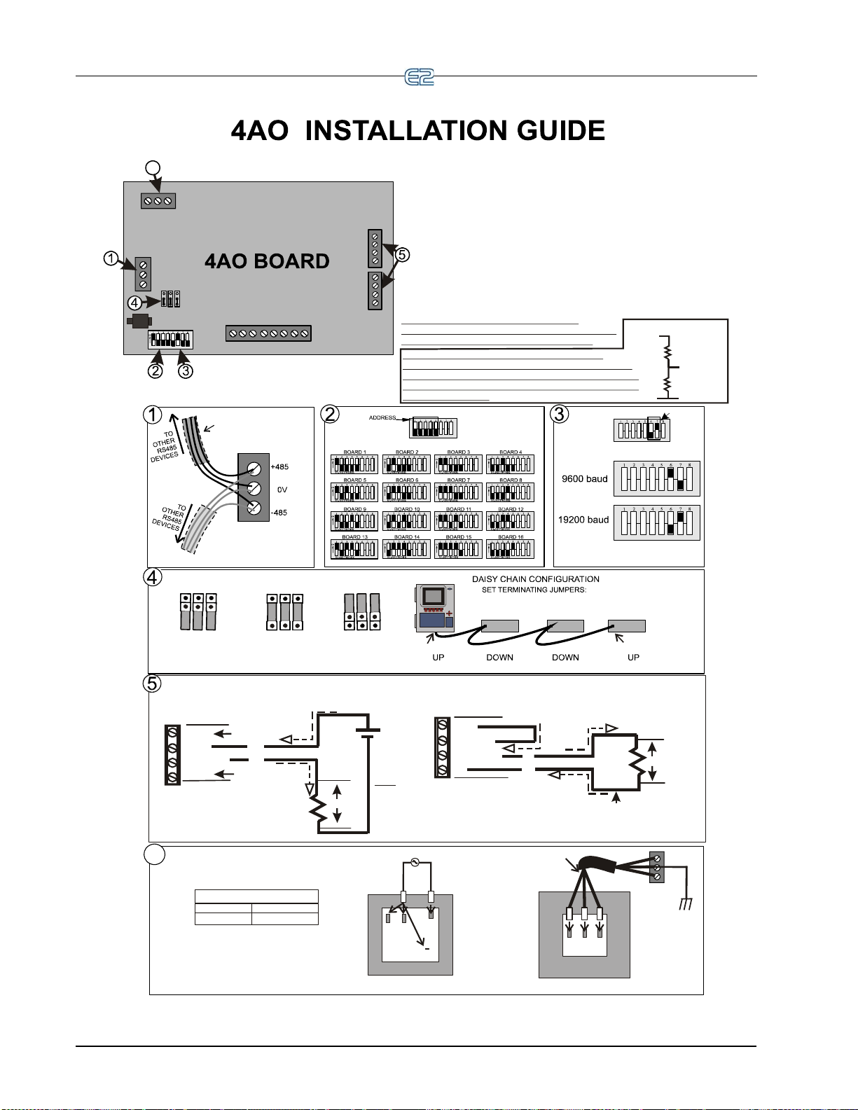
CAUTION: If you change any dip switch
settings while the board is powered, disconnect
the power and re-power the board to reset.
WIRING FOR 640-0056, 56VA Transformer,
and 640-0080, 80VA Transformer
24VAC Center-Tapped Transformer
PRIMARY SIDE
240 208
C
120
(
N
E
U
T
R
A
L
)
(
H
O
T
)
120/208/240 VAC
L2
L1
Three-conductor non-shielded cables
are the recommended wire
for connecting between the
center-tapped transformer
and I/O boards.
Power Wiring Types:
14 AWG Belden 9495
18 AWG Belden 9493
SECONDARY SIDE
24V CT 24V
AC10VAC2
AC1
AC2
0V
SHIELDED TWISTED PAIR
BELDEN #8761. FOR PLENUM,
USE BELDEN #82761 OR #8 87 61
OR EQUIV.
WIRE + to + (same color)
WIRE 0V to 0V
WIRE - to - (same color)
BAUD RATE
1. Connect the 4AO board to the RS485 I/O Network.
2. Set the network address on the first five
rockers of dip switch S1.
3. Set the network baud rate using rockers 6
and 7 of dip switch S1.
4. If the E2 is the beginning of all RS-485 I/O or MODBUS
Networks, set all three jumpersto the UP position. For MODBUS,
set thejumpers in the top-most position (MOD). ForI/O Net, set the
jumpers in the middle position(I/O). For no termination, set the
jumpers tothe DOWN position (NO).
5. Optionally, connect the 4-20mA outputs in either a 2-wire
or 4-wire hookup as illustrated in Step 5, or if a 4-20mA is
not used, it may be left unconnected.
6. Connect board to the 24VAC secondary
of the power transformer.
center-tapped
(Term)
(Term)
I
/
O
N
E
T
Note
:
Either the “2-wire” or “4-wire”
Hookup may be used at either
4-20mA output. The Hookups may
be the same or different. If a 4-20mA
is not used, it may be left unconnected.
“2-wire” 4-20mA
(Externally Powered)
Hookup example.
(Isolated)
+12V
+4-20
4-20 OUT
0V
+
+
_
_
24V
1-5V
Not Used
Not Used
4-20mA
Analog
Output
4-20mA
Analog
Output
“4-wire” 4-20mA
(Internally Powered)
Hookup example.
(Not Isolated)
+12V
+4-20
4-20 OUT
0V
_
+
250 ohms
Jumper
Grounded
1-5V
6
6
250 ohms
+
V
OUT
15-K
15-K
+
--V
IN
NOTE: The voltage divide function capability
on the previous model (P/N 810-3030) 4AO board is
no longer supported. This can now be accomplished
by using two external 15-K resistors. If used with E2,
scale output range.
NOT TERMINATED TERMINATED
FOR I/O NET
MOD
I/O
NO
MOD
I/O
NO
TERMINATED
FOR MODBUS NET
MOD
I/O
NO
[
[
[
[
[
[
[
[
[
6-18 • E2 RX/BX/CX I&O Manual 026-1614 Rev 4 5-JAN-2013
Page 75

BACnet The RS485 Network and Hardware Setup • 6-19
Page 76

WIRE + to + (same color)
WIRE 0V to 0V
WIRE - to - (same color)
SHIELDED TWISTED PAIR
BELDEN #8761. FOR PLENUM,
USE BELDEN #82761 OR #88761
OR EQUIV.
YELLOW
YELLOW
0V
24 VAC
24 VAC
120/208/240 VAC
•
P/N 640-0041, 120VAC Primary,
50VA
•
P/N 640-0050, 120VAC Primary,
75VA
•
P/N 640-0042, 220VAC Primary,
50VA
• P/N 640-0056, Multi-tap
120/208/240VAC Primary, 56VA
• P/N 640-0080, Multi-tap
120/208/240VAC Primary, 80VA
Note: Please refer to transformer
for primary side wiring.
Acceptable Retail Solutions Transformers:
NOT TERMINATED TERMINATED
FOR I/O NET
MOD
I/O
NO
MOD
I/O
NO
TERMINATED
FOR MODBUS NET
MOD
I/O
NO
[
[
[
[
[
[
[
[
[
5. If the E2 is the beginning of all RS-485 I/Oor MODBUS
Networks, set all three jumpersto the UP position. For MODBUS,
set thejumpers in the top-most position (MOD). ForI/O Net, set
the jumpers in the middle position(I/O). For no termination, set
the jumpers tothe DOWN position (NO).
6-20 • E2 RX/BX/CX I&O Manual 026-1614 Rev 4 5-JAN-2013
Page 77

32
2
5
34
1
1.
2. Connect 16A1 to the RS485 I/O Network.
3. Set the network address on the first five
rockers of dip switch S3.
4. Set the network baud rate using rockers 6
and 7 of dip switch S3.
5. If the E2 is the beginning of all RS-485 I/O or
MODBUS Networks, set all three jumpers to the
UP position. For MODBUS, set the jumpers in
the top-most position (MOD). For I/O Net, set the
jumpers in the middle position(I/O). For no termination,
set the jumpers tothe DOWN position (NO).
6. If you change any dip switch settings
while the board is powered, disconnect the
power and re-power the board to reset.
Connect board to power transformer.
2
SHIELDED TWISTED PAIR
BELDEN #8761
OR EQUIV.
T
O
O
T
H
E
R
R
S
48
5
D
E
V
I
C
E
S
T
O
O
T
H
E
R
R
S
4
8
5
D
E
V
I
C
E
S
WIRE + to +
WIRE 0V to 0V
WIRE - to -
3
2345678
1
ON
2345678
1
ON
2345678
1
ON
2345678
1
ON
2345678
1
ON
2345678
1
ON
2345678
1
ON
2345678
1
ON
2345678
1
ON
2345678
1
ON
2345678
1
ON
2345678
1
ON
2345678
1
ON
2345678
1
ON
2345678
1
ON
2233445566778
8
1
1
ON
BOARD 1 BOARD 2 BOARD 3
BOARD 4
BOARD 5 BOARD 6 BOARD 7
BOARD 8
BOARD 9
BOARD 10
BOARD 11
BOARD 12
BOARD 13
BOARD 14
BOARD 15
BOARD 16
ADDRESS
4
2
2
2
3
3
3
4
4
4
5
5
5
6
6
6
7
7
7
8
8
8
1
1
1
BAUD RATE
9600 baud
19200 baud
16AI INSTALLATION GUIDE
DAISY CHAIN CONFIGURATION
SET TERMINATING JUMPERS:
UP DOWN DOWN UP
5
1
WIRING FOR 640-0056, Three Board Xformer,
and 640-0080, Five Board Xformer
WIRING FOR 640-0048, Ten Board Xformer
208/230 VAC
652112
11
8
7
AC10VAC2
24 VAC OUTPUT
CENTER TAP
FOR 208/230 VAC POWER SOURCE
120 VAC
652112
11
8
7
AC10VAC2
24 VAC OUTPUT
CENTER TAP
FOR 120 VAC POWER SOURCE
PINOUT
625112811
7
PRIMARY SIDE SECONDARY SIDE
240 208
C
120
B
L
U
E
(
N
E
U
T
R
A
L
)
B
R
O
W
N
(
H
O
T
)
120/208/240 VAC
24V CT 24V
AC10VAC2
NOT TERMINATED
TERMINATED
FOR I/O NET
MOD
I/O
NO
MOD
I/O
NO
TERMINATED
FOR MODBUS NET
MOD
I/O
NO
[
[
[
[
[
[
[
[
[
BACnet The RS485 Network and Hardware Setup • 6-21
Page 78
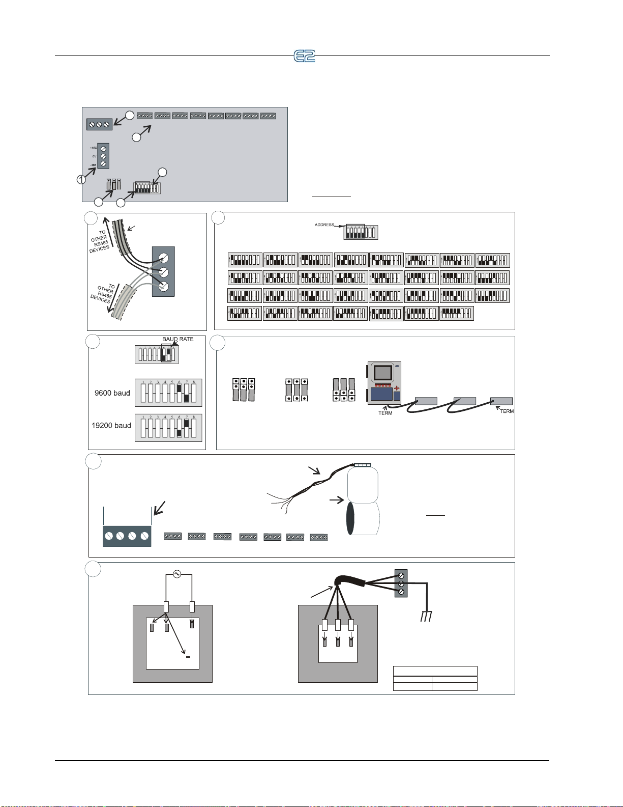
MultiFlex ESR INSTALLATION GUIDE
1. Connect the MultiFlex ESR to the I/O Network.
RS485 I/O NET
S1
Set the network address
using the first 5 rockers
of dip switch S1.
Valid address range 1-31.
2345678
1
ON
2345678
1
ON
2345
678
1
ON
2345678
1
ON
BOARD 1 BOARD 2 BOARD 3 BOARD 4
2345678
1
ON
2345678
1
ON
2345678
1
ON
2345678
1
ON
BOARD 5
BOARD 6
BOARD 7
BOARD 8
2345678
1
ON
2345678
1
ON
2345
678
1
ON
2345678
1
ON
BOARD 9 BOARD 10 BOARD 11 BOARD 12
2345678
1ON2345678
1ON2345678
1ON2345678
1
ON
BOARD 13 BOARD 14
BOARD 15
BOARD 16
2345678
1
ON
2345678
1
ON
2345
678
1
ON
2345678
1
ON
BOARD 17 BOARD 18 BOARD 19 BOARD 20
2345678
1ON2345678
1ON2345678
1
ON
BOARD 21
BOARD 22
BOARD 23
2345678
1
ON
BOARD 24
2345678
1
ON
2345678
1
ON
23456
7
8
1
ON
2345678
1
ON
BOARD 25 BOARD 26 BOARD 27 BOARD 28
2345678
1
ON
BOARD 29
2345678
1
ON
2345678
1
ON
BOARD 30
BOARD 31
WIRE + to + (same color)
WIRE SHIELD TO CENTER PIN
WIRE - to - (same color)
0V
SHIELDED TWISTED P AI R
BELDEN #8761. FOR PLENUM,
USE BELDEN #82761, 88761,
OR EQUIV.
I/O N
ET
+485
-485
1
2
3
4
POWER
AC2
AC1
GND
I/
ONE
T
S1
JP2 JP3
JP4
NETWORK
2
3
4
5
ECT Flow
ESR 12 or
ESR 20 Valve
Stepper valve harness
Valve connectors on the
MultiFlex ESR board (1-8)
For Sporlan valves match
all wire colors the
green wire. Instead, connect
the green wire to the silk screen
blue wire legend.
except
Use the cable harnesses
that are supplied with the valves.
(A valve cable harness may not
be longer than 150 feet)
6
5
WIRING FOR 640-0080, 80VA,
24VAC Center-Tapped Transformer
Power Wiring Types:
14 AWG Belden 9495
18 AWG Belden 9493
PRIMARY SIDE
240 208
C
120
(
N
E
U
T
R
A
L
)
(
H
O
T
)
120/208/240 VAC
L2
L1
SECONDARY SIDE
Three-conductor non-shielded cables
are the recommended wire
for connecting between the
center-tapped transformer
and MultiFlex ESR boards.
24V CT 24V
AC1
GND
AC2
AC1
AC2
24VAC Center-Tapped
Earth ground the
GND (center-tapped)
terminal of each board
GND
6
4. If the E2 is the beginning of all RS-485 I/O or MODBUS Networks,
set all three jumpers to the UP position. For MODBUS, set the jumpers
in the top-most position (MOD). ForI/O Net, set the jumpers in the
middle position(I/O). For no termination, set the jumpers tothe DOWN position (NO).
2. Set the network address on the first fi ve roc kers of th e
dip switch (labeled S1) on the MultiFlex ESR board.
3. Set the network baud rate using rockers 6 and 7.
6. Connect the MultiFlex ESR to a Class 2, 80VA
24VAC power transformer. (One MultiFlex ESR board
per transformer.) For more information on transformer wiring,
refer to the MultiFlex ESR manual ( ).
center-tapped
P/N 026-1720
5. Wire each stepper valve by connecting the stepper valve
harness to one of the eight connectors along the top
of the board.
VALVE 1 VALVE 2
VALVE 3 VALVE 7
VALVE 4
VALVE 5
VALVE 6
VALVE 8
VALVE 4
VALVE 5 VALVE 6
VALVE 7 VALVE 8
VALVE 3
VALVE 2
Valve 1 connector
enlarged to show
harness wire color
orientation:
BLU
R BLK
W
Wire color legend silk screened
on each valve connector (8)
(Match wire colors to
silk screen legend
on valve connectors)
NOT TERMINATED TERMINATED
FOR I/O NET
MOD
I/O
NO
MOD
I/O
NO
TERMINATED
FOR MODBUS NET
MOD
I/O
NO
[
[
[
[
[
[
[
[
[
6-22 • E2 RX/BX/CX I&O Manual 026-1614 Rev 4 5-JAN-2013
Page 79

BACnet The RS485 Network and Hardware Setup • 6-23
Page 80

6-24 • E2 RX/BX/CX I&O Manual 026-1614 Rev 4 5-JAN-2013
Page 81

Page 82

Page 83

7 E2 Ethernet Peer Communications
Communication between E2 controller version 2.10 or
greater may now be implemented through an Ethernet network using TCP/IP protocol. To utilize peer connections
hernet, the following tasks must be performed:
over Et
• Upgrade the E2 controller firmware to version 2.10
or greater
• Install an industry-standard Ethernet switch(es) or
hub(s)
• Install Ethernet straight-through cabling at the site
from
RJ-45 connectors may be necessary to achieve this
goal. The recommended cabling is CAT 5.
.
in an area or areas nearby the E2 controllers.
each E2 to the switch or hub. Installation of
7.1 Ethernet IP Configurations
If using an open network configuration (see Section
Open Network Layout), contact your IT Network
7.4.2,
Administrator for all IP configuration information (IP
ress, Subnet Mask, Primary and Default Gateway set-
Add
tings).
7.2.1 Components
Equipment Type Specifications
Ethernet Five- or
Ni
ne-port Switch
(may require an
additional power
supply)
Ethernet Surge
d Lightning
an
Protector (recommended)
* Industrial grade
* Operating/storage temp range:
-40°F to 185°F
* Vibration: IEC68-2-6
* RH: 5 to 95%
* UL 508A, CE approved
* Supports 10Base-T crossover
cable
* Supports all IEEE 802.3 proto-
col
* Supports Auto Crossover
MDI/MDI-X
* Screw-terminal power connec-
tors
* Industrial grade
* Surge capacity: 1 kA / line
*Operating temp range: -40°F to
5°F
18
*Max frequency: 155 MHz
*Clamp and rated: 10V and 5V
7.2 Hardware Specifications
Standard industry-accepted practices for wiring of
Ethernet networks are expected. E2 controllers use a star
topology, identical to PC deployment. This includes a
unique “point-to-point” run from a switch or hub to the
controller (see Table 7-1 for hub part numbers for order-
ing). This is done with Category5 (or better) cable. Maximum distance for a run of 10BaseT is 328 feet (100
ers) (11.5 dB loss max).
met
• The maximum number of controllers allowed on an
bnet is 20. All E2 controllers that must com-
IP su
municate with each other must be on the same subnet.
• Recommended Ethernet cabling is CAT 5 (straight-
h cable).
throug
• 328 feet (100 meters) is the maximum distance
wed between devices before a switch or hub
allo
must be added.
10-Base-T/100Base-TX Hu
10-Base-T/100Base-TX Hu
Ta ble 7-1 - Equipment for E2 Ethernet Peer Communications
b
b
NOTE: An external power supply may be
needed.
Room Temperature (0 to 50 C)
P/N 570-0100
Extended Temperature
(-40 to 65 C) P/N 570
-0200
Ethernet IP Configurations E2 Ethernet Peer Communications • 7-1
Page 84

7.3 Software Specifications
TCP/IP
E2 controller versions 2.10 and later communicate
between controllers using the TCP/IP protocol. TCP Port
7238 is the default for connections established between the
controllers. All peer communications occur over this port.
7.4 Ethernet Network
Layouts
The two types of network options for E2 controllers
using Ethernet communications are:
1. “Closed Network” - E2 devices are not connected
to a st
ore’s LAN. (The only devices on the net-
work are the E2 controllers themselves.) This
ork type is used if there is no need to inte-
netw
grate the network into the company’
2. “Open Network” - E2 devices ar
the store’s LAN. (Devices on the network include
E2s and other Ethernet-TCP/IP devices.) This
network type is used if the network will be connected to the store’s LAN.
s intranet.
e connected to
NOTE: The gateway E2 is the E2 controller at
a remote site to which UltraSite directly con-
nects. It is through this E2 that UltraSite communicates with the other controllers
“non-gateway” E2s and external entities such as UltraSite, InSite, Site Manager etc.).
(defined as the
7.4.1 Closed Network Layout
NOTE: Contact your IT Network Administrator for setup parameters for both closed and
open netwo
The E2 peer Ethernet network fac
tions between E2 controllers. Thes
following:
• Routing of messages between external entities
such as
non-gateway E2 controllers.
• Distribution of global data and other network
variables such as
tification, etc.
• Communication between E2 controller applications such as Remote Login and Remote File
Services.
rks.
ilitates communica-
e include at least the
UltraSite, InSite, Site Manager, and
system time, controller iden-
Figure 7-1 - Closed Network Layout
7-2 • E2 RX/BX/CX I&O Manual 026-1614 Rev 4 5-JAN-2013
Page 85

7.4.2 Open Network Layout
Figure 7-2 - Open Network Layout
Figure 7-3 - TCP/IP Setup Screen
3. Tab over to the Peer Netwrk tab:
7.5 Software Setup
1. Log on to the E2 controller
2. Navigate to the TCP/IP
NOTE: DHCP does not have to be enabled if
you have the IP Address, Subnet Mask, and
Primary Gateway se
Network Administrator for all IP configuration information.) If you do not have the IP configuration settings, and there is a DHCP server on the network, set
HCP Enabled to Yes and it will retrieve the informa-
D
tion from the server and populate those fields. E2 controllers must all have the same Ether
order to communicate box-to-box.
setup screen (Alt + T)
ttings. (Contact your IT
net Subnet in
Figure 7-4
- Peer Network Tab - Set Network Type
4. Change Network Type to: Ethernet (ETH) and
press Enter. The Group Name field is now visi-
ble.
NOTE: If unsure of any tab settings, it is recommended that the default settings be used.
5. Once the Ethernet network
a unique site name in the Group Name field.
NOTE: The site name is the unique identifier
for the site that will allow the controllers
hin the same group to share data.
wit
type is enabled, enter
Software Setup E2 Ethernet Peer Communications • 7-3
Page 86

Figure 7-5 - Peer Network Tab - Set Group Name
All controllers that you would like to appear in this group
must all have the same group name and must be using the
same network type.
7.6 Troubleshooting
Network troubleshooting is outside the scope of this
section (Section 7, E2
Consult your IT Network Administrator for any additional
information needed.
Ethernet Peer Communications).
7-4 • E2 RX/BX/CX I&O Manual 026-1614 Rev 4 5-JAN-2013
Page 87

8 Echelon Network and Hardware Setup
8.1 Overview
Echelon is an optional, two-conductor network that interconnects E2s and other associated devices, such as CC-100
case controllers, TD3 temperature displays, and ESR8 evaporator stepper regulator boards. All Echelon devices are wired
together using the daisy-chain method of network structuring. If an Echelon network-enabled E2 is required, it must be
specifically ordered from Emerson Retail Solutions as an Echelon-enabled E2, and equipped with an Echelon plug-in
card. See Section 4.3.1, Echel
8.2 Wiring Type
Emerson Retail Solutions specifies one type of cable for Echelon Network wiring. This cable type’s properties are
listed in Table 8-1.
on Plug-In Card Kit (P/N 638-4860).
Cable Type Lev e l 4, twisted pair, stranded, shielded
Wire Diam./AWG 0.65mm/22AWG
Loop Resistance 106(ohms/km)
Capacitance 49(nF/km)
Ta ble 8-1 -
Echelon Network Cable Specifications
Cable Type
1 pair, non-plenum 135-2300
1 pair, plenum 135-2301
Ta ble 8-2
- Recommended Wiring
8.3 Echelon Network Structuring (Daisy-Chains)
Echelon devices are networked together into configurations called segments.
Echelon devices that are connected together on an unbroken series of wires.
The recommended way of constructing an Echelon
work is called daisy-chaining. In the daisy-chain net-
Net
work configuration, devices are arranged by subnets,
ch consist of one E2 and all Echelon devices associ-
whi
ated with the E2.
First, all devices in a subnet are connected in an unbroken chain without branches or “star configurations” (see
Figure 8-1). Then, if more than one E2 is present on-site,
A segment is a group of up to 64
Emerson Retail Solutions Part
Number
all chains are connected so that the entire network forms a
ge unbroken chain, called a daisy chain
lar
(see Figure 8-2). This allows for all devices in the Echelon Network to be hard wired together for trouble free
communication.
Overview Echelon Network and Hardware Setup • 8-1
Page 88

Figure 8-1 - Echelon Wiring - Subnets
E2
E2
E226513125rev
RECOMMENDED
UNBROKEN
CHAIN
E2s
J2
J2
E2
Termination
multiple routers can be used to extend the network indefinitely.
More information about routers and how they are used
a daisy-chain Echelon Network can be found in the
in
Router and Repeater Installation Guide (P/N 026-1605).
8.4 Device Termination
In a daisy-chain configuration, both ends of the net-
work segment must be terminated. T
setting jumper J2 to the UP position, as shown in Figure
8-3. Other devices on the Echelon Network are terminated
either by jumpers on the control board or by connecting a
2-ohm “terminator block” at the end of the network seg-
10
ment (see Section 8.4.1, Usin
535-2715) to Terminate a Daisy Chain). Refer to the
installation guide references at the end of this section for
specific devi
ce termination instructions.
All other E2s and Echelon device
end of a daisy-chained network segment must be unterminated.
If a router or repeater is being
nation becomes more complicated, becaus
repeaters join multiple daisy-chain segments together.
Refer to the Router and Repeater Installation Guide (P/N
026-1605), for specific termination instructions.
erminate the E2 by
g a Te rmination Block (P/N
s that aren’t at the
used in a network, termi-
e routers and
Figure 8-2 - Echelon Wiring, pt. 2
8.3.1 Maximum Number of Echelon Devices
A daisy-chained segment may contain no more than 63
total Echelon devices (also called "nodes"). If there are 64
or more Echelon devices at your site, an Echelon-compatible router (P/N 572
-4200) will be required. A router
placed on the Echelon Network allows you to add another
63-node daisy-chain network. For larger installations,
8-2 • E2 RX/BX/CX I&O Manual 026-1614 Rev 4 5-JAN-2013
Figure 8-3 - E2 T e rmination - Daisy Chain
Page 89

8.4.1 Using a Termination Block (P/N 535-2715) to Terminate a Daisy Chain
Some Echelon Network devices, notably TD3s, have
no on-board means of terminating. For some other
devices, it is inconvenient to use the jumpers supplied for
termination (the CC-100/CS-100 case controllers, for
example, require the enclosure to be removed to set the
jumper).
To remedy these problems, Emerson Retail Solutions
ies termination blocks that can be wired to the end of
suppl
an Echelon cable segment. This termination block uses the
same three-pin connector as all other Echelon devices.
Wire the two signal wires to the outside terminals, and
connect the shield to the middle terminal (see Figure 8-4).
a maximum of 63 more nodes.
Repeaters bo
instances where a segment of 63 nodes or less uses more
than 4592 feet of Echelon cable.
Refer to the Rout
(P/N 026-1605), for information about router and repeater
placement.
ost signal strength and are only used in
er and Repeater Installation Guide
8.6 Installing Echelon Devices
The E2 control system has several types of peripheral
control boards that communicate using the Echelon Network: the 16AIe analog
put board, the CC-100/CS-100 series of case control and
circuit control boards, and the ESR8 board.
case
input board, the 8ROe relay out-
NOTE: The recommended termination procedure for all Echelon devices is the termination
ck.
blo
Figure 8-4
- Placement and Wiring of the Termination Block
8.5 Wire Restrictions
8.6.1 Powering Echelon Devices
CAUTION: Do not power Echelon devices
with the same 56VA and 80VA transformers
to power the I/O Network. Echelon
used
devices require Class 2 power to operate, which is not
supplied by the I/O board transformers.
All Echelon devices require 24VAC Class 2 power.
Emerson
ers to accommodate the full range of Emerson Retail Solutions’ Echelon-compatible products. Table 8-3 lists each
transformer’s part number and rating.
Retail Solutions specs several sizes of transform-
Xformer P/N VA Rating Input Voltage
640-0039 10 VA 110 VAC
640-0041 50 VA 110 VAC
640-0042 50 VA 220 VAC
640-0050 75 VA 110 VAC
640-0045 75 VA 220 VAC
Maximum Total Segment Length
The total amount of wire used to connect all E2s and
associated controllers in a single segment (not including
devices on the other side of routers) cannot be longer than
4592 feet (1400 meters). If the total length of cable used is
longer than 4592 feet, a repeater or router will be required.
Routers act as
the amount of network traffic. They are used when networks exceed their 63-node limit. Adding
you to add another daisy-chain segment of 4592 feet with
Wire Restrictions Echelon Network and Hardware Setup • 8-3
communication gateways that reduce
a router allows
Ta ble 8-3
devices:
- Class 2 Transformers for Echelon Devices
To select a power transformer for one or more Echelon
1. Determine what the total VA is for the boards
and
controllers that will be powered by the
transformer (see Table 8-4).
Example: Two TD3 boards (4 VA each), and
one E2 (40
one transformer. The total VA is:
VA) board are to be powered by
Page 90

2 4VA 1 40VA+ 48VA=
2. Use a transformer that has a power rating
equal to or higher than the total calculated
VA (see
Example: Boards totaling 48VA can be connected to
either a
Table 8-4
fo
lon Network.
50VA or 75VA transformer.
Unit amps VA VA C Center
E2 1.66 40 24 No
ESR8 2.4 75 24 No
TD3 0.11 4 24 No
CC-100/
CS-100
- Device Power Requirements
Refer to the installation guides on the next few pages
r instructions on how to install these boards on the Eche-
Ta ble 8-3).
tapped?
Power supplied by Power Module
8.7 LEDs
Echelon Board Status
Red (D1) (Reset) ON: The Echelon port is being
hel
d in reset or if momentary it
means the board has gone
through reset
Red (Service) During normal operation this
LED shou
Pin is pressed, this LED will
come on.
If the LED is blinking, the node
do
address set. (E2 should set this
during the first power -up sequence where the user will be
asked in whi
controller (E2 will always be
Node = 1 on the network).
If the LED is blinking, then try
reset
correct the problem, replace the
Echelon board.
ld be off. If the Service
es not have its Subnet/Node
ch Subnet to put the
ting the E2. If this does not
The Echelon Board LEDs can be used to determine the
status of normal operating parameters for the board.
Ta ble 8-5 -
ON (no blinking): Replace the
Echelon board. The Neuron processor has lost its application
program.
Echelon LED Status
8.8 Open Echelon Device Connectivity
Open-Echelon E2s must be ordered pre-configured
from Emerson Retail Solutions. Open-Echelon licenses
must be purchased and enabled on units, and are not transferrable to other units without assistance from Emerson
ail Solutions. Call 770-425-2724 for technical assis-
Ret
tance or your sales representative. Your sales representative will know which devices your unit will connect to.
8.8.1 Configuring Echelon Devices
Login to the controller and enter the desired number of
Echelon devices to be added in the Connected I/O screen.
From the Main Menu:
1. Select
(System Configuration)
8-4 • E2 RX/BX/CX I&O Manual 026-1614 Rev 4 5-JAN-2013
2. Select
3. Select
(Network Setup)
(Connected I/O Boards and Control-
Page 91

lers)
Enter the number of Echelon devices you wish to add
on the Connected I/O screen:
Highlight the LonMark device on the screen you wish
to commission and follow the steps in Section 10.14.2,
Commissioning a Device to commission the device.
8.8.1.1 Troubleshooting
After commissioning has been completed, check to
make sure the device has been added successfully. From
the Main Menu, select
open the Configured Applications list. If the device you
have commissioned does not appear in this list, the
Description File has failed to upload correctly onto the E2.
An alarm of No Description File will be generated and
can be found in the Alarm Advisory Log. Call Emerson
Retail Solutions at 770-425-2724 to contact your sales representative or technical assis
tion File.
(Configured Applications) to
tance to obtain the Descrip-
Figure 8-5
Party Tab section of the Connected I/O setup screen and
enter the number of Echelon devices to be added.
is done at th
nected I/O screen, hit the back butt
Network setup menu and select
from the Main Menu:
screen:
- Connected/IO Setup Screen (RX Unit Shown)
Navigate to the Open Echelon field under the Third
Next, commission the Echelon device. Commissioning
e Controller Setup screen. If still on the Con-
on to go back to the
(Controller Setup). Or ,
1. Select
2. Select
3. Select
Commission the device on the Network Summary
(System Configuration)
(Network Setup)
(Network Summary)
Figure 8-6
Open Echelon Device Connectivity Echelon Network and Hardware Setup • 8-5
- Network Summary Screen (RX Unit Shown)
Page 92

8-6 • E2 RX/BX/CX I&O Manual 026-1614 Rev 4 5-JAN-2013
Page 93
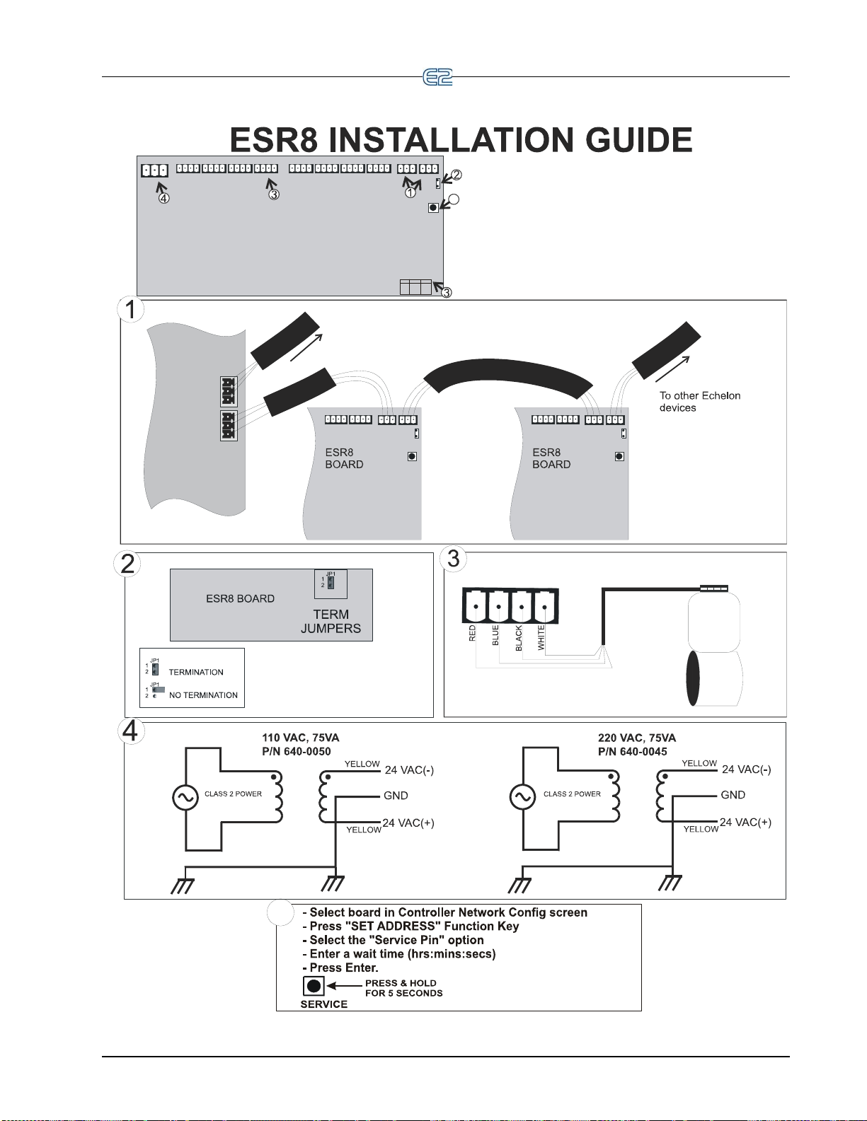
3. Wire each Emerson Flow Controls ESR12 or ESR20
valve to one of the four-pin connectors on the ESR8. (Refer to
the Emerson Flow Controls Valve Field Wiring Guide.) Use
Belden #9418 18AWG or equivalent.
4. Connect the ESR8 to a Class 2, 75 VA 24VAC transformer.
1. Connect the ESR8 to the Echelon Network.
2. Set the termination jumper on the ESR8. For daisy chain
configurations, the device will need to be terminated
only if at either end of a daisy chain.
5. Use the Service Button to commission the ESR8. Refer to
section 8.14.4 in this manual for more information on
commissioning a device. Note that dip switches (S2 & S3) are not
implemented.
To other Einsteins/E2s,
or Echelon devices
Level IV, 22 AWG, Shielded
Max Daisy Chain Length:
Feet: 4592 Meters: 1400
P/N 135-2300 Non-Plenum
P/N 135-2301 Plenum
(1 Pair, 1000 Feet)
(1 Pair, 1000 Feet)
ECHELON CABLE TYPE
Pin#
Color
Phase
1
2
3
4
Red
Blue
Black
White
A1
A2
B1
B2
Emerson Flow Controls
Valve Field Wiring
Guide
5
NOTE: Leave jumper hanging on
one pin when unterminating an
ESR8 so the jumper will be
available for future use. For an
alternative termination method,
refer to section 8.4.1. of this manual.
Emerson Flow Controls
ESR12 or ESR20
Valve #4
Pin 1
(Refer to the Emerson
Flow Controls Valve
Field Wiring Guide)
5
NOTE:
For Sporlan CDS
and SEI valves,
use GREEN wire
where BLUE wire
is connected in
the diagram.
Use cable harness supplied with valve OR
use 18AWG wire (no longer than 75 ft.) OR
14AWG wire (no longer than 200 ft.)
Open Echelon Device Connectivity Echelon Network and Hardware Setup • 8-7
Page 94

8-8 • E2 RX/BX/CX I&O Manual 026-1614 Rev 4 5-JAN-2013
Page 95
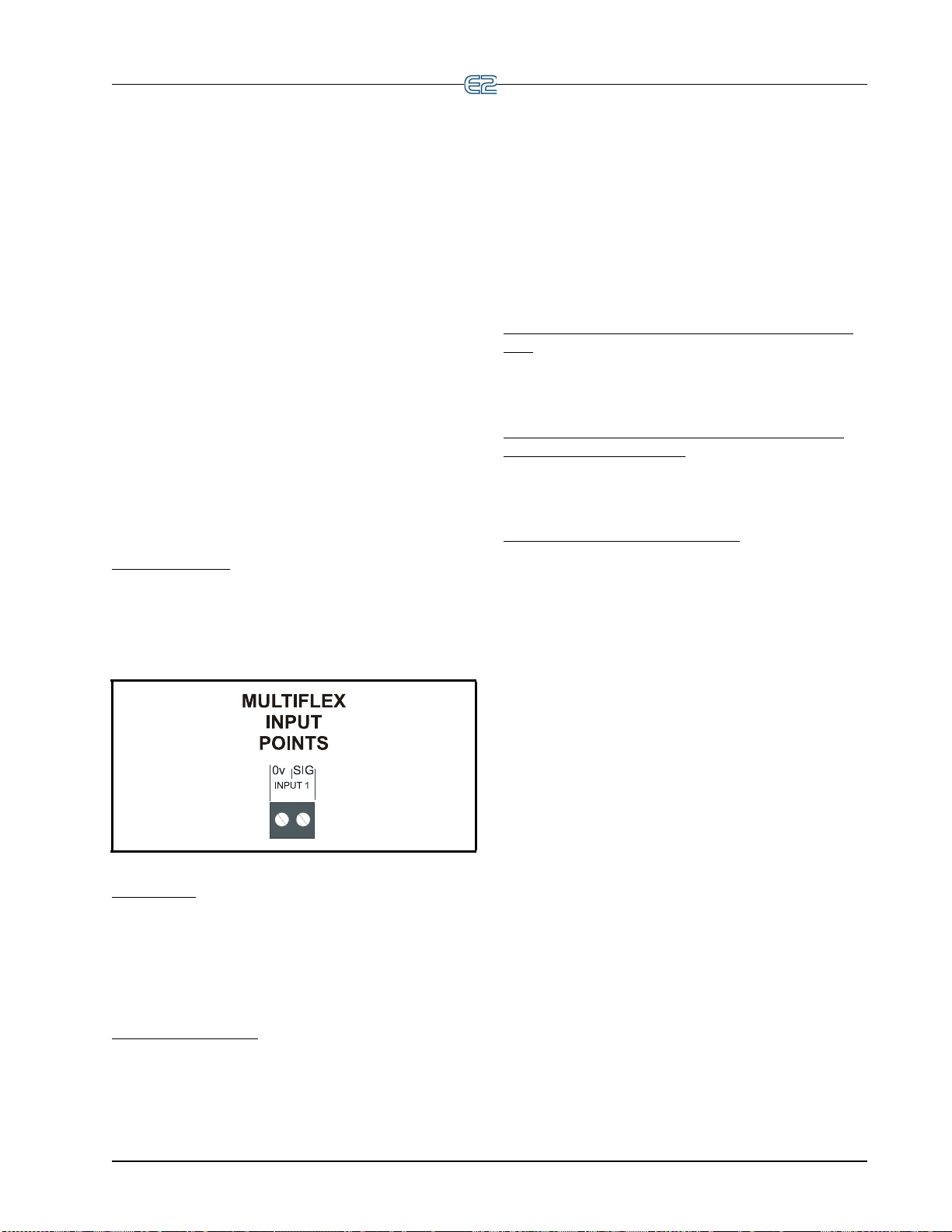
9 Input and Output Setup
9.1 The 16AI, 8IO, and MultiFlex Inputs
9.1.1 Connecting Sensors to Input Boards
There are five I/O Network boards that may accept
inputs: the MultiFlex, the 16AI, the ARTC, and the 8IO
Combination Input/Output Board. Wiring an input to these
boards requires three steps:
1. Connect the sensor’s signal wires to the two terminals of an input point.
2. Set the input type dip switch that corresponds to
the point
3. If necessary, connect t
to one of the 5V or 12V power terminals.
9.1.1.1 Wiring
MultiFlex Boards
An input point connector on a MultiFlex, 16AI, and
16AIe board consists of two terminals, as shown in Figure
9-1. One of these terminals, labeled
nal from the sensor, while the other, labeled “0v” is where
’s ground and/or cable shield wire is connected.
sensor
Figure 9-1
16AI Boards
On a 16AI, terminals are numbered 1-32, starting with
the first terminal of point 1 and ending with the last terminal of point 16. The even-numbered terminals of a 16AI
are always
sensor grounds and cable shields are connected to the oddnumbered terminals.
8IO and ARTC Boards
labeled “-” or “+”. The ground wire is always connected to
the “-” terminal, and the signal wire is connected to the
where the signal voltages are connected. The
On an 8IO board, the two terminals of every point are
being connected.
he power lead of the sensor
“SIG”, reads the sig-
- Input Board Points
“+” terminal.
On the ARTC board, the input and output points are
predefined and are
labeled accordingly.
9.1.1.2 Sensor Wiring Types
Specific wiring types are required for each type of sen-
sor used with E2.
All Analog Temperature Sensors and Air Flow Sensors
Temperature and air flow sensors are to be wired with
shielded, 2 conductor, at least 22 GA wire (Belden # 8761
or equivalent).
All Pressure Transducers, Humidity Sensors, and
Refrigeration Transducers
Pressure and refrigeration transducers and humidity
sensors are to be wired with shielded, 3 conductor, at least
22 GA wire (Belden #8771 or equivalent).
Dewpoint and Light Level Sensors
These sensors are to be wired with shielded, 4 conductor at least 22 GA wire (Belden # 8729 or equivalent).
9.1.1.3 Input Type Dip Switches
An input type dip switch must be set for each input
point. Input type dip switches are located in the switch
banks labeled S1 and S2 on the MultiFlex, 16AI, and
switch bank S4 on the 8IO.
The input type dip switch tells the input board whether
the sensor connected to the point requires a DC sup-
or not
ply voltage in order to operate. If the sensor requires DC
ltage, the dip switch should be set to the DOWN posi-
vo
tion. If the sensor does not require power, or if it uses AC
wer, the dip switch should be set to the UP position. Dip
po
switches for unused points should be set to the UP position.
The dip switch positions for each specific s
is shown in Figure 9-2.
ensor type
The 16AI, 8IO, and MultiFlex Inputs Input and Output Setup • 9-1
Page 96

Figure 9-2 - Input Typ e Dip Switches for MultiFlex 16 and 16AI
26501070
2233445566778
8
1
1
ON
ON
S1
S2
INPUTS 9-16
INPUTS 1-8
Set DOWN for
sensors requiring
voltage
Set UP for
sensors not requiring
voltage
Boards
9.1.2 Power Connection
If power is needed to operate the sensor, several terminals exist on the 16AI, Multiflex boards, 8IO, that may be
used to
MultiFlex power connections).
supply DC power (see Figure 9-3 for 16AI and
Figure 9-3 - Input Board Power Sources
to one of the DC power sources, simply connect the sensor’s power wire to one of the terminals.
+12V
rent that can be drawn from all three +5VDC terminals
COMBINED is 50 mi
given in Table 9-1 on page 9-3.
9-2 • E2 RX/BX/CX I&O Manual 026-1614 Rev 4 5-JAN-2013
Input boards may supply 12VDC or 5VDC. To connect
The maximum current that may be drawn from the
DC terminal is 100 milliamps. The maximum cur-
lliamps.
NOTE: For 24VAC sensors, a separate transformer must be used unles
s specified other-
wise in Table 9-1 on page 9-3.
Specific wiring instructions
for each type of sensor are
Page 97

P/N Sensor
various Temp Sensors
and Probes
various Digital Sensors
(Klixons, Sail
Switches, etc.)
800-2100
800-2200
800-2500
Pressure Transducers (Emerson Retail
Solutions) 100,
200, 500
lb. rat-
ings
(0.5-4.5VDC
output, 5VDC
input voltage)
Input Type
Dip Switch
Up
Up
Up
Wiring
1. Connect one lead to the odd
numbered terminal and the
ot
her lead to the even num-
bered terminal (polarity
nsensitive).
i
1. Connect one lead to the odd numbered
terminal and the other lead to the even
n
umbered terminal (polarity insensitive).
1. Connect RED power
wire to +5VDC supply on input board.
2. Connect WHITE signal wire to even numbered terminal.
3. Connect BLACK
round wire to odd
g
numbered terminal.
4. Connect the bare
wire to odd
SHIELD
numbered terminal.
203-5750 Relative Humid-
ity Sensor
Ta ble 9-1 - Sensor Wiring
Down
1. Wire the “P”
sensor terminal
to 12VDC supply on board.
2. Wire the
3. Wire the
4. Jumper sensor
ensor
“GND” s
terminal to odd
numbered terminal.
ensor
“OUT” s
terminal to even
numbered terminal.
erminal “N” to
t
sensor terminal
“GND”.
The 16AI, 8IO, and MultiFlex Inputs Input and Output Setup • 9-3
Page 98

B
LA
C
K
W
HI
T
E
S
H
I
E
L
D
B
L
A
C
K
W
H
I
T
E
WALL-MOUNT
DEWPOINT SENSOR
BACK PLATE
(FRONT VIEW)
B
E
L
D
E
N
#
8
7
6
1
O
R
E
Q
U
I
V
A
L
E
N
T
S
H
I
E
L
D
(
C
L
I
P
)
MULTIFLEX INPUT BOARD
(BOTTOM LEFT CORNER SHOWN)
8
7
6
54321
12
120 VAC
24 VAC
(P/N 640-0039)
Signal
Ground
0-5V
Output
Separate
Transformer
P/N Sensor
Input Type
Dip Switch
Wiring
203-5751
Wall-mounted
relative
humidity (RH)
sensor
210-2002 Wall-mounted
dewpoint sensor
Down
Down
1. Use Belden #8771 shielded three-conductor cable or equivalent.
2. Connect the RED, BLACK, and WHITE wires to
nector as shown in Figu
3. Connect the SHIELD and BLACK wires to the 0
the WHITE wire to the SIG terminal of the input board.
re 2. Clip the SHIELD wire.
the screw terminals the sensor’s con-
V terminal of the input board. Connect
4. Connect the RED wire to the +12V power terminal on the input board.
5. Locate the input dip switch for the sensor point, and set to the OFF position (LEFT for
ultiFlex, DOWN for 16AI). Refer to the input board’s user manual for locations of the
M
input dip switches.
1. For wiring the sensor to a Emerson Retail Solutions input board, use Belden #8761
shielded two-conductor cable or equivalent.
2. Connect the BLACK and WHITE wires to the s
as shown in
(connect BLACK to Signal Ground and WHITE to 0-5V Output). Clip the
Figure 3
crew terminals on the sensor’s connector
SHIELD wire.
3. Connect the SHIELD and BLACK wires to the 0
the WHITE wire to the SIG terminal of the input board.
4. Connect 24VAC (a separate 120VAC/24
to the power terminal on the dewpoint sensor back plate using the BLACK and WHITE
wires. (This 24VAC transformer must only be used to power this dewpoint sensor. Do
V terminal of the input board. Connect
VAC transformer must be used P/N 640-0039)
not use this transformer to power additional devices.)
5. Locate the input dip switch for the sensor point, and set to the OFF position (LEFT for
ultiFlex, DOWN for 16AI). Refer to the input board’s user manual for locations of the
M
input dip switches.
206-0002 Light Level
Down
1. Wire GREEN ground wire
to odd numbered terminal.
2. Wire YELLOW and RED
ignal wires to even num-
s
bered terminal.
3. Wire the POWER wire to a
VDC source on input
+12
board.
Ta ble 9-1
9-4 • E2 RX/BX/CX I&O Manual 026-1614 Rev 4 5-JAN-2013
- Sensor Wiring
Page 99

P/N Sensor
Input Type
Dip Switch
Wiring
207-0100 Analog Liquid
Level
207-1000 Refrigerant
Level Transducer (Hansen
Probe)
Down
Down
1. Connect RED
power wire to
+12VDC source
on input board.
2. Connect BLACK
round wire to
g
odd numbered terminal.
3. Connect GREEN
ignal wire to
s
even numbered
terminal.
1. Wire BLACK ground
wire from “GND”
sensor terminal to odd
numbered board terminal.
2. Wire GREEN signal
from “SIGNAL”
wire
sensor terminal to
even numbered board
terminal.
3. Wire RED power wire
from “P
OWER” sen-
sor terminal to
12VDC terminal on
+
board.
203-1902 Dewpoint Probe
Ta ble 9-1
- Sensor Wiring
Up
1. Connect the WHITE
and GREEN wires to
AC1 and AC2 power
terminals.
2. Connect BLACK
round wire to odd
g
numbered board terminal.
3. Connect RED signal
to even numbered
wire
board terminal.
The 16AI, 8IO, and MultiFlex Inputs Input and Output Setup • 9-5
Page 100

P/N Sensor
Input Type
Dip Switch
Wiring
550-2500
550-2550
Ta ble 9-1
KW Transducer
- Sensor Wiring
Down for 420mA, Up for
Pulse
4-20 mA output to input board
1. Wire positive transducer terminal
to positive 24VDC supply.
2. Wire negative transducer terminal to odd numbered input terminal.
3. Wire negative 24VDC supply to
umbered input terminal.
even n
4. Place 250 r
and even numbered input terminals.
esistor across odd
Pulse Accumulator output to input board
1. If the input board is an 8IO or a 16AI version
E.02 or greater, connect the two KWh terminals
t
o the input point (polarity insensitive)
2. If the input board is a 16AI version less than
.02, connect the KWh terminals to board point
E
1. Set input switch #1 DOWN, and set input
switch #8 UP.
3. If the input board is a 16AIe, connect the two
terminals to input # 1, 2, 3, or 4 ONLY.
KWh
9.1.3 Input Setup in E2
At this point in the setup process, you should have all
sensors, transducers, and other input devices wired to
points on MultiFlexes, 16AIs, and all output devices connected to 8ROs, 8DOs, or 4AOs outputs. Once the physical wiring is complete, you will need to tell E2 the types of
sensors
This is achieved in the Input and Output Definitions
screens.
9.1.3.1 Configuring a Point from the Input Definitions/Status Screen
screen by pressing Alt + I or:
or devices that are connected to each I/O point.
T o configure a point, go to the Input Definitions/Status
1. Press
2. Press
3. Press
to open the Main Menu
(System Configuration)
(Input Definitions)
The Input Status screen opens:
Figure 9-4 - Input Status Screen
Use the up and down arrow keys to move the cursor to
the point you wish to set up, and press (SETUP).
A pop-up menu such as the one shown in Figure 9-5
will prompt you to specify the point as analog or digital.
if the input is analog, press if the input is dig-
Press
9-6 • E2 RX/BX/CX I&O Manual 026-1614 Rev 4 5-JAN-2013
 Loading...