


 Loading...
026-1614 Rev 4 5-JAN-2013
E2 Installation and Operation Manual for RX Refrigeration, BX HVAC, and CX Convenience Store Controllers
Applicable to E2 firmware versions 4.0 and above

Emerson Climate Technologies Retail Solutions
1065 Big Shanty Road NW, Suite 100
Kennesaw, GA 30144, USA
Phone 770-425-2724
Fax 770-425-9319
E2 FIRMWARE VERSION
4.05F01
FCC COMPLIANCE NOTICE
This device complies with Part 15 of the FCC Rules. Operation is subject to the following two conditions: (1) this device may not cause harmful interference, and (2) this device must accept any interference received, including interference that may cause undesired operation.
CE COMPLIANCE NOTICE
Class A Product Information for E2 Controllers:
The Emerson Retail Solutions Einstein and E2 controllers are Class A products. In a domestic environment this product may cause radio interference in which case the user may be required to take adequate measures. This covers:
•All E2 family product types: RX - Refrigeration Controller (845-xxxx), BX - Building/HVAC Controller (845-xxxx), CXConvenience Store Controller (845-xxxx), and all version models: (300, 400, 500).

TABLE OF CONTENTS
1 |
INTRODUCTION............................................................................................................... |
....................................... 1-1 |
|
1.1 |
THE E2 REFRIGERATION CONTROLLER (RX)............................................................................................................ |
1-1 |
|
1.2 |
THE E2 BUILDING CONTROLLER (BX)...................................................................................................................... |
1-2 |
|
1.3 |
THE E2 CONVENIENCE STORE CONTROLLER (CX)................................................................................................... |
1-3 |
|
1.4 |
NETWORKING OVERVIEW.......................................................................................................................................... |
1-4 |
|
1.4.1 |
E2 I/O Network .................................................................................................................................................. |
1-4 |
|
1.4.2 The E2 Echelon Lonworks Network................................................................................................................... |
1-5 |
||
1.4.3 Interconnection With Other E2s ........................................................................................................................ |
1-5 |
||
1.5 |
DOCUMENTATION OVERVIEW ................................................................................................................................... |
1-6 |
|
1.6 |
ON-LINE HELP SYSTEM OVERVIEW .......................................................................................................................... |
1-7 |
|
1.7 |
SOFTWARE LICENSING............................................................................................................................................... |
1-7 |
|
2 |
HARDWARE OVERVIEW...................................................................................................................................... |
2-1 |
|
2.1 |
E2 HARDWARE .......................................................................................................................................................... |
2-1 |
|
2.1.1 E2 Main Processor Board (CPU)...................................................................................................................... |
2-2 |
||
2.1.2 E2 Processor Interface Board (PIB).................................................................................................................. |
2-2 |
||
2.1.3 |
E2 Keypad .......................................................................................................................................................... |
2-2 |
|
2.1.4 |
LEDs................................................................................................................................................................... |
2-2 |
|
2.2 |
I/O NETWORK BOARDS AND PERIPHERALS............................................................................................................... |
2-3 |
|
2.2.1 |
The Gateway Board ........................................................................................................................................... |
2-3 |
|
2.2.2 |
MultiFlex Boards ............................................................................................................................................... |
2-4 |
|
|
|
2.2.2.1 MultiFlex 16 Input Board ........................................................................................................................................ |
2-4 |
|
|
2.2.2.2 MultiFlex Combination Input/Output Boards.......................................................................................................... |
2-4 |
|
|
2.2.2.3 MultiFlex CUB ........................................................................................................................................................ |
2-6 |
|
|
2.2.2.4 MultiFlex RTU (BX and CX Only)......................................................................................................................... |
2-6 |
|
|
2.2.2.5 MultiFlex Rooftop Control Board (RCB) (BX and CX Only) ................................................................................ |
2-6 |
|
|
2.2.2.6 MultiFlex PAK Board.............................................................................................................................................. |
2-6 |
2.2.3 The MultiFlex ESR Board .................................................................................................................................. |
2-7 |
||
2.2.4 Hand-held Terminal (P/N 814-3110)................................................................................................................. |
2-7 |
||
2.2.5 The 8RO and 8ROSMT Relay Boards................................................................................................................ |
2-8 |
||
2.2.6 4AO Analog Output Board................................................................................................................................. |
2-9 |
||
2.2.7 8DO Digital Output Board and PMAC II Anti-Sweat Controller ..................................................................... |
2-9 |
||
2.3 |
ECHELON NETWORK BOARDS AND PERIPHERALS................................................................................................... |
2-10 |
|
2.3.1 |
The 16AIe (Discontinued) ................................................................................................................................ |
2-10 |
|
2.3.2 |
The 8ROe (Discontinued)................................................................................................................................. |
2-10 |
|
2.3.3 |
EC-2s................................................................................................................................................................ |
2-11 |
|
2.3.4 CC-100 Case Controllers and CS-100 Case Circuit Controllers.................................................................... |
2-11 |
||
2.3.5 |
TD3 Temperature Display ............................................................................................................................... |
2-12 |
|
2.3.6 Facility Status Display (FSD) .......................................................................................................................... |
2-12 |
||
3 |
MOUNTING............................................................................................................................................................... |
3-1 |
|
3.1 |
MOUNTING THE E2.................................................................................................................................................... |
3-1 |
|
3.1.1 |
Standard Mount.................................................................................................................................................. |
3-1 |
|
3.1.2 |
Recessed Mount.................................................................................................................................................. |
3-1 |
|
3.1.3 |
Retrofit Mounting............................................................................................................................................... |
3-2 |
|
3.1.4 |
Blank Face ......................................................................................................................................................... |
3-3 |
|
3.2 |
MOUNTING I/O BOARDS............................................................................................................................................ |
3-3 |
|
3.2.1 |
Single/Double Enclosures ................................................................................................................................. |
3-3 |
|
3.2.2 Boards Without Enclosures (Snap Track).......................................................................................................... |
3-4 |
||
E2 RX/BX/CX I&O Manual |
Table of Contents • v |

3.3 ECHELON DEVICES ............................................................................................................................... |
..................... 3-5 |
||
3.3.1 CC-100 Case Controller and CS-100 Case Circuit Controller ......................................................................... |
3-5 |
||
3.3.2 |
MultiFlex ESR .................................................................................................................................................... |
3-5 |
|
3.3.3 |
TD3.................................................................................................................... |
................................................. |
3-5 |
3.4 COM3 INTERNAL MODEM PLUG-IN CARD |
|
||
(P/N 638-3362)................................................................................................................. |
................................................. |
3-5 |
|
3.4.1 Two-Channel and Four-Channel Repeaters ...................................................................................................... |
3-6 |
||
|
3.4.1.1 |
Mounting Repeaters Overview ................................................................................................................................ |
3-6 |
|
3.4.1.2 Mounting the Two-Channel Repeater...................................................................................................................... |
3-6 |
|
|
3.4.1.3 Mounting the Four-Channel Repeater ..................................................................................................................... |
3-6 |
|
3.5 SENSORS AND TRANSDUCERS.................................................................................................................................... |
3-7 |
||
3.5.1 |
Pressure Transducers......................................................................................................................................... |
3-7 |
|
|
3.5.1.1 |
Mounting.................................................................................................................................................................. |
3-7 |
3.5.2 |
Inside Temperature Sensor................................................................................................................................. |
3-7 |
|
|
3.5.2.1 |
Location ................................................................................................................................................................... |
3-7 |
|
3.5.2.2 |
Mounting.................................................................................................................................................................. |
3-7 |
3.5.3 |
Outside Temperature Sensor.............................................................................................................................. |
3-7 |
|
|
3.5.3.1 |
Location ................................................................................................................................................................... |
3-7 |
|
3.5.3.2 |
Mounting.................................................................................................................................................................. |
3-7 |
3.5.4 |
Insertion Temperature Probe ............................................................................................................................. |
3-8 |
|
|
3.5.4.1 |
Location ................................................................................................................................................................... |
3-8 |
|
3.5.4.2 |
Mounting.................................................................................................................................................................. |
3-8 |
3.5.5 Supply and Return Air Sensors........................................................................................................................... |
3-8 |
||
3.5.6 Refrigeration System Temperature Probes and Sensors.................................................................................... |
3-8 |
||
|
3.5.6.1 |
Location ................................................................................................................................................................... |
3-8 |
|
3.5.6.2 Mounting Bullet and Pipe Mount Sensors............................................................................................................... |
3-8 |
|
3.5.7 |
Product Temperature Probes ............................................................................................................................. |
3-9 |
|
3.5.8 Humidity Sensors and Humidistats .................................................................................................................... |
3-9 |
||
|
3.5.8.1 |
Indoor RH Sensor .................................................................................................................................................... |
3-9 |
|
3.5.8.2 |
Outdoor RH Sensors ................................................................................................................................................ |
3-9 |
|
3.5.8.3 Duct-mounted Insertion RH Probe ........................................................................................................................ |
3-10 |
|
3.5.9 |
Dewpoint Probe................................................................................................................................................ |
3-10 |
|
|
3.5.9.1 |
Location ................................................................................................................................................................. |
3-10 |
|
3.5.9.2 |
Mounting................................................................................................................................................................ |
3-10 |
3.5.10 |
Light Level Sensor.......................................................................................................................................... |
3-10 |
|
|
3.5.10.1 |
Location ............................................................................................................................................................... |
3-10 |
|
3.5.10.2 |
Mounting.............................................................................................................................................................. |
3-10 |
3.5.11 |
Liquid Level Sensors ...................................................................................................................................... |
3-11 |
|
3.5.12 |
Refrigerant Leak Detectors ............................................................................................................................ |
3-11 |
|
4 E2 HARDWARE SETUP .......................................................................................................................................... |
4-1 |
||
4.1 SETTING UP THE E2 ................................................................................................................................................... |
4-1 |
||
4.1.1 |
Enclosure............................................................................................................................................................ |
4-1 |
|
4.1.2 |
Main Processor Board ....................................................................................................................................... |
4-1 |
|
4.1.3 Power Interface Board (PIB) ............................................................................................................................. |
4-2 |
||
4.2 POWERING THE E2..................................................................................................................................................... |
4-2 |
||
4.2.1 |
RS485 Ports........................................................................................................................................................ |
4-2 |
|
4.2.2 RS485 Termination Jumpers (MODBUS or I/O Net)......................................................................................... |
4-2 |
||
4.2.3 |
Echelon Network Connect.................................................................................................................................. |
4-2 |
|
4.2.4 |
Echelon Jumper.................................................................................................................................................. |
4-2 |
|
4.3 ADD-ON E2 PERIPHERALS......................................................................................................................................... |
4-2 |
||
4.3.1 Echelon Plug-In Card Kit |
|
||
(P/N 638-4860) ............................................................................................................................................................. |
4-2 |
||
4.3.2 COM3 RS232 Plug-In for External Modem (P/N 638-4875) ............................................................................ |
4-3 |
||
4.3.3 COM3 Internal Modem Plug-In Card (P/N 638-3362) .................................................................................... |
4-3 |
||
vi • Table of Contents |
026-1614 Rev 4 5-JAN-2013 |

4.3.4 Plug-In Digital I/O Network Card (P/N 638-4880)........................................................................ |
................... 4-3 |
|||
|
|
4.3.4.1 |
LEDs ........................................................................................................................................................................ |
4-3 |
4.3.5 Plug-In Four-Channel Internal Repeater .......................................................................................................... |
4-3 |
|||
5 |
SERIAL CONFIGURATION................................................................................................................................... |
5-1 |
||
5.1 |
OVERVIEW ............................................................................................................................... |
.................................. |
5-1 |
|
5.2 |
COM PORTS |
.............................................................................................................................................................. |
5-1 |
|
5.3 SERIAL DEVICE AND SOFTWARE SETUP .................................................................................................................... |
5-1 |
|||
6 THE RS485 NETWORK AND HARDWARE SETUP .......................................................................................... |
6-1 |
|||
6.1 |
THE I/O NETWORK .................................................................................................................................................... |
6-1 |
||
6.1.1 I/O Board Names and Terminology ................................................................................................................... |
6-1 |
|||
6.1.2 |
MultiFlex-Plus (+) Board .................................................................................................................................. |
6-2 |
||
|
|
6.1.2.1 |
Board Designation ................................................................................................................................................... |
6-2 |
|
|
6.1.2.2 |
Board Calculations................................................................................................................................................... |
6-2 |
6.1.3 |
Wiring Types ...................................................................................................................................................... |
6-2 |
||
6.1.4 The I/O Network Structure (Daisy Chains)........................................................................................................ |
6-2 |
|||
6.1.5 |
Network Noise Minimization.............................................................................................................................. |
6-3 |
||
6.1.6 Network ID Numbers (Board Numbers) ............................................................................................................ |
6-3 |
|||
6.1.7 Setting the Baud Rate......................................................................................................................................... |
6-3 |
|||
6.1.8 Setting the Terminating and Biasing Jumpers ................................................................................................... |
6-4 |
|||
6.1.9 Powering the I/O Boards ................................................................................................................................... |
6-4 |
|||
|
|
6.1.9.1 |
Wiring Types ........................................................................................................................................................... |
6-5 |
6.1.10 |
Board Installation ............................................................................................................................................ |
6-6 |
||
6.2 IMC/PRODIGY ROOFTOP UNIT CONTROLLERS.......................................................................................................... |
6-6 |
|||
6.3 |
MODBUS................................................................................................................... |
............................................... |
6-6 |
|
6.3.1 Control Techniques Drive (VSD)....................................................................................................................... |
6-6 |
|||
6.3.2 Copeland Discus with CoreSense Diagnostics (ISD) ........................................................................................ |
6-7 |
|||
6.3.3 XR35CX, XR75CX, and XEV22 Case Controllers............................................................................................. |
6-7 |
|||
|
|
6.3.3.1 |
XR75CX-Case Display............................................................................................................................................ |
6-7 |
6.3.4 |
iPro DAC............................................................................................................................................................ |
6-7 |
||
6.3.5 |
Energy Meter...................................................................................................................................................... |
6-7 |
||
|
|
6.3.5.1 |
Overview.................................................................................................................................................................. |
6-7 |
|
|
6.3.5.2 |
Supported System Types.......................................................................................................................................... |
6-8 |
6.3.6 Modular Refrigerant Leak Detection Sensor (MRLDS) ................................................................................... |
6-8 |
|||
6.3.7 Copeland Discus with CoreSense Protection ................................................................................................... |
6-8 |
|||
6.3.8 |
Copeland CoreSense Communications.............................................................................................................. |
6-8 |
||
6.3.9 |
Light Commercial Thermostat ........................................................................................................................... |
6-9 |
||
|
|
6.3.9.1 |
Thermostat Inputs .................................................................................................................................................... |
6-9 |
|
|
6.3.9.2 |
Advisory and Alarms ............................................................................................................................................... |
6-9 |
6.3.10 Refrigerant Leak Detection System (RLDS)................................................................................................... |
6-11 |
|||
|
|
6.3.10.1 |
Diagnostic Alarms ............................................................................................................................................... |
6-12 |
6.3.11 Copeland Scroll – K5 Refrigeration Compressor.......................................................................................... |
6-12 |
|||
6.3.12 XM Series of Case Controllers...................................................................................................................... |
6-12 |
|||
|
|
6.3.12.1 |
XM670 ................................................................................................................................................................. |
6-12 |
|
|
6.3.12.2 |
XM679 ................................................................................................................................................................. |
6-12 |
|
|
6.3.12.3 |
XM678 ................................................................................................................................................................. |
6-12 |
6.4 |
BACNET ............................................................................................................................... |
................................... |
6-13 |
|
6.4.1 |
BACnet Overview............................................................................................................................................. |
6-13 |
||
6.4.2 |
BACnet Communication................................................................................................................................... |
6-13 |
||
|
|
6.4.2.1 Master Slave Token Passing .................................................................................................................................. |
6-13 |
|
|
|
6.4.2.2 BACnet IP (Internet Protocol) ............................................................................................................................... |
6-14 |
|
|
|
6.4.2.3 |
Discovery ............................................................................................................................................................... |
6-14 |
|
|
6.4.2.4 |
Client-Server.......................................................................................................................................................... |
6-14 |
6.4.3 MS/TP Network Connection to E2 ................................................................................................................... |
6-14 |
|||
E2 RX/BX/CX I&O Manual |
Table of Contents • vii |

|
|
6.4.3.1 Add and Connect a BACnet Device ...................................................................................................................... |
6-14 |
|
7 E2 ETHERNET PEER COMMUNICATIONS ...................................................................................................... |
7-1 |
|||
7.1 |
ETHERNET IP CONFIGURATIONS................................................................................................................................ |
7-1 |
||
7.2 |
HARDWARE SPECIFICATIONS ..................................................................................................................................... |
7-1 |
||
7.2.1 |
Components........................................................................................................................................................ |
7-1 |
||
7.3 |
SOFTWARE SPECIFICATIONS ...................................................................................................................................... |
7-2 |
||
7.4 |
ETHERNET NETWORK LAYOUTS ................................................................................................................................ |
7-2 |
||
7.4.1 |
Closed Network Layout ...................................................................................................................................... |
7-2 |
||
7.4.2 |
Open Network Layout......................................................................................................................................... |
7-3 |
||
7.5 |
SOFTWARE SETUP ...................................................................................................................................................... |
7-3 |
||
7.6 |
TROUBLESHOOTING ................................................................................................................................................... |
7-4 |
||
8 ECHELON NETWORK AND HARDWARE SETUP........................................................................................... |
8-1 |
|||
8.1 |
OVERVIEW |
............................................................................................................................... .................................. |
8-1 |
|
8.2 |
WIRING TYPE............................................................................................................................................................. |
8-1 |
||
8.3 |
ECHELON NETWORK STRUCTURING (DAISY-CHAINS) .............................................................................................. |
8-1 |
||
8.3.1 Maximum ..............................................................................................................Number of Echelon Devices |
8-2 |
|||
8.4 |
DEVICE TERMINATION............................................................................................................................................... |
8-2 |
||
8.4.1 Using a .........................................................Termination Block (P/N 535-2715) to Terminate a Daisy Chain |
8-3 |
|||
8.5 |
WIRE RESTRICTIONS.................................................................................................................................................. |
8-3 |
||
8.6 |
INSTALLING ................................................................................................................................ECHELON DEVICES |
8-3 |
||
8.6.1 |
Powering .................................................................................................................................Echelon Devices |
8-3 |
||
8.7 |
LEDS ......................................................................................................................................................................... |
|
8-4 |
|
8.8 |
OPEN ECHELON ...................................................................................................................DEVICE CONNECTIVITY |
8-4 |
||
8.8.1 |
Configuring .............................................................................................................................Echelon Devices |
8-4 |
||
|
|
8.8.1.1 ....................................................................................................................................................... |
Troubleshooting |
8-5 |
9 INPUT AND ................................................................................................................................OUTPUT SETUP |
9-1 |
|||
9.1 |
THE 16AI, 8IO, .................................................................................................................AND MULTIFLEX INPUTS |
9-1 |
||
9.1.1 Connecting ..................................................................................................................Sensors to Input Boards |
9-1 |
|||
|
|
9.1.1.1 ...................................................................................................................................................................... |
Wiring |
9-1 |
|
|
9.1.1.2 ................................................................................................................................................ |
Sensor Wiring Types |
9-1 |
|
|
9.1.1.3 .........................................................................................................................................Input Type Dip Switches |
9-1 |
|
9.1.2 |
Power ..............................................................................................................................................Connection |
9-2 |
||
9.1.3 Input Setup ................................................................................................................................................in E2 |
9-6 |
|||
|
|
9.1.3.1 ................................................................................Configuring a Point from the Input Definitions/Status Screen |
9-6 |
|
|
|
9.1.3.2 ...............................................................................................................Using the Input Definitions/Status Screen |
9-7 |
|
|
|
9.1.3.3 .........................................................................................................................................Setting Up Analog Inputs |
9-7 |
|
|
|
9.1.3.4 .........................................................................................................................................Setting Up Digital Inputs |
9-9 |
|
9.2 |
THE 8RO, 8IO, ............................................................................................................AND MULTIFLEX OUTPUTS |
9-10 |
||
9.2.1 Wiring ..................................................................................................................................Form C Contacts |
9-10 |
|||
9.2.2 |
MultiFlex ..................................................................................................................................Relay Outputs |
9-10 |
||
9.2.3 Setting ......................................................................................................................the Fail-Safe Dip Switch |
9-11 |
|||
9.2.4 Relay Output ...................................................................................................................................Test Mode |
9-11 |
|||
9.2.5 Wiring .................................................................................................................................Outputs to Points |
9-12 |
|||
9.2.6 |
The Output ...............................................................................................................................................LED |
9-12 |
||
9.2.7 Output ...........................................................................................................................................Setup in E2 |
9-12 |
|||
|
|
9.2.7.1 ...........................................................................Configuring a Point from the Output Definitions/Status Screen |
9-12 |
|
|
|
9.2.7.2 ..........................................................................................................Using the Output Definitions/Status Screen |
9-13 |
|
|
|
9.2.7.3 .....................................................................................................................................Setting Up Digital Outputs |
9-13 |
|
|
|
9.2.7.4 ....................................................................................................................................Setting Up Analog Outputs |
9-14 |
|
9.3 |
CC-100 CASE ..................................................................................................................................CONTROLLERS |
9-16 |
||
9.3.1 |
Inputs................................................................................................................................................................ |
|
9-16 |
|
9.3.2 |
Power ......................................................................................................................................Module Wiring |
9-17 |
||
viii • Table of Contents |
026-1614 Rev 4 5-JAN-2013 |

9.3.3 Valve Cable ...................................................................................................................................................... |
9-17 |
|||
9.4 CCB CASE CONTROLLERS ...................................................................................................................................... |
9-18 |
|||
9.5 ESR8 AND MULTIFLEX ESR VALVE OUTPUT WIRING........................................................................................... |
9-18 |
|||
10 QUICK START...................................................................................................................................................... |
10-1 |
|||
10.1 |
LOGGING ON ......................................................................................................................................................... |
10-1 |
||
10.2 CLEANING OUT THE CONTROLLER........................................................................................................................ |
10-1 |
|||
10.3 SETTING NUMBER OF NETWORK DEVICES ............................................................................................................ |
10-2 |
|||
10.4 SETTING NUMBER OF APPLICATIONS .................................................................................................................... |
10-3 |
|||
10.5 THE MAIN STATUS (HOME) SCREEN..................................................................................................................... |
10-3 |
|||
10.5.1 Customizing the Home Screen ....................................................................................................................... |
10-3 |
|||
10.6 |
COMMON SCREEN ELEMENTS ............................................................................................................................... |
10-4 |
||
10.6.1 |
The Header..................................................................................................................................................... |
10-4 |
||
|
|
10.6.1.1 |
Header Icons ........................................................................................................................................................ |
10-4 |
10.6.2 |
The Function Keys ......................................................................................................................................... |
10-4 |
||
10.6.3 |
The Help Line................................................................................................................................................. |
10-4 |
||
10.7 |
SCREEN TYPES....................................................................................................................................................... |
10-5 |
||
10.7.1 |
The Main Menu .............................................................................................................................................. |
10-5 |
||
10.7.2 |
Status Screens ................................................................................................................................................ |
10-5 |
||
10.7.3 |
The Actions Menu........................................................................................................................................... |
10-6 |
||
10.7.4 |
The Setup Screens .......................................................................................................................................... |
10-6 |
||
10.7.5 |
System Configuration Menu........................................................................................................................... |
10-7 |
||
10.7.6 The System Information Menu ....................................................................................................................... |
10-8 |
|||
10.8 |
TIME/DATE SETUP ................................................................................................................................................. |
10-9 |
||
10.8.1 Setting the Time and Date.............................................................................................................................. |
10-9 |
|||
10.9 |
SET UP MODEM ................................................................................................................................................... |
10-10 |
||
10.10 |
SET UP TCP/IP.................................................................................................................................................. |
10-11 |
||
10.11 SET UP NETWORK BAUD RATES ...................................................................................................................... |
10-12 |
|||
10.11.1 COM1 Serial (RS232) Baud Rate .............................................................................................................. |
10-12 |
|||
10.11.2 I/O Network Baud Rate .............................................................................................................................. |
10-12 |
|||
10.12 SET UP USER ACCESS ....................................................................................................................................... |
10-13 |
|||
10.12.1 Changing Required User Access Levels .................................................................................................... |
10-14 |
|||
10.12.2 Creating a New User Account ................................................................................................................... |
10-14 |
|||
10.12.3 |
Deleting a User .......................................................................................................................................... |
10-14 |
||
10.13 SET UP I/O NETWORK ....................................................................................................................................... |
10-15 |
|||
10.13.1 Specify Number of Boards.......................................................................................................................... |
10-15 |
|||
10.13.2 |
Checking Online Status.............................................................................................................................. |
10-15 |
||
10.14 SET UP ECHELON NETWORK ............................................................................................................................. |
10-16 |
|||
10.14.1 Specifying Number of Devices ................................................................................................................... |
10-16 |
|||
10.14.2 |
Commissioning a Device............................................................................................................................ |
10-16 |
||
|
|
10.14.2.1 The Service Button Method ............................................................................................................................. |
10-17 |
|
|
|
10.14.2.2 The Manual ID Entry Method.......................................................................................................................... |
10-18 |
|
10.15 |
LICENSE MANAGEMENT .................................................................................................................................... |
10-19 |
||
10.15.1 |
Web Services .............................................................................................................................................. |
10-20 |
||
10.16 |
SET UP ALARMING ............................................................................................................................................ |
10-20 |
||
10.16.1 Specifying Alarm Reporting Types............................................................................................................. |
10-21 |
|||
|
|
10.16.1.1 |
The Display Line.............................................................................................................................................. |
10-21 |
|
|
10.16.1.2 |
The Alarm Output............................................................................................................................................ |
10-21 |
|
|
10.16.1.3 |
Dial-Out ........................................................................................................................................................... |
10-21 |
|
|
10.16.1.4 The Echelon Network (The Alarm Annunciator) ............................................................................................ |
10-21 |
|
10.16.2 Setting up an E2 to be an Alarm Annunciator ........................................................................................... |
10-22 |
|||
10.16.3 |
Alarm Dial-Out .......................................................................................................................................... |
10-22 |
||
10.16.4 |
Introduction: Alarm Reporting .................................................................................................................. |
10-23 |
||
10.17 SET UP GLOBAL DATA...................................................................................................................................... |
10-23 |
|||
E2 RX/BX/CX I&O Manual |
Table of Contents • ix |

10.17.1 |
Priority Settings.......................................................................................................................................... |
10-24 |
||
10.18 SET UP APPLICATIONS....................................................................................................................................... |
10-25 |
|||
10.18.1 |
Add/Delete an Application ......................................................................................................................... |
10-26 |
||
10.18.2 Using and Configuring a Setup Screen...................................................................................................... |
10-26 |
|||
|
|
10.18.2.1 |
The Edit Menu ................................................................................................................................................. |
10-27 |
|
|
10.18.2.2 |
Entering Setpoints............................................................................................................................................ |
10-27 |
|
|
10.18.2.3 Navigating the Setup Screen............................................................................................................................ |
10-27 |
|
10.18.3 Using the Help Key to get Property Help .................................................................................................. |
10-29 |
|||
11 |
SOFTWARE OVERVIEW ................................................................................................................................... |
11-1 |
||
11.1 |
SUCTION GROUPS .................................................................................................................................................. |
11-1 |
||
11.1.1 |
Introduction.................................................................................................................................................... |
11-1 |
||
11.1.2 The (Standard) Suction Group Application ................................................................................................... |
11-1 |
|||
|
|
11.1.2.1 Overview of PID Control Strategy ...................................................................................................................... |
11-1 |
|
|
|
11.1.2.2 |
Variable-Speed Compressors............................................................................................................................... |
11-1 |
|
|
11.1.2.3 |
Floating Setpoint Control..................................................................................................................................... |
11-1 |
11.1.3 The Enhanced Suction Group Application..................................................................................................... |
11-1 |
|||
|
|
11.1.3.1 |
Learning Mode..................................................................................................................................................... |
11-2 |
|
|
11.1.3.2 |
Circuit Load Analysis .......................................................................................................................................... |
11-2 |
|
|
11.1.3.3 |
The Control/Cycles Parameter............................................................................................................................. |
11-2 |
|
|
11.1.3.4 Variable-Speed, Digital Scroll, and Digital Discus Compressor Support ........................................................... |
11-2 |
|
|
|
11.1.3.5 |
Floating Suction Control...................................................................................................................................... |
11-2 |
11.1.4 |
Hardware Overview ....................................................................................................................................... |
11-2 |
||
11.2 |
CONDENSER CONTROL........................................................................................................................................... |
11-3 |
||
11.2.1 |
Air Cooled Condensers .................................................................................................................................. |
11-3 |
||
|
|
11.2.1.1 |
Air Cooled Strategy ............................................................................................................................................. |
11-3 |
|
|
11.2.1.2 |
Temperature Differential Strategy ....................................................................................................................... |
11-3 |
11.2.2 |
Evaporative Condensers ................................................................................................................................ |
11-4 |
||
11.2.3 |
Fan Control .................................................................................................................................................... |
11-4 |
||
11.2.4 |
Condenser Split Mode .................................................................................................................................... |
11-4 |
||
11.2.5 |
Fast Recovery................................................................................................................................................. |
11-4 |
||
11.2.6 |
Hardware Overview ....................................................................................................................................... |
11-4 |
||
11.3 |
STANDARD CIRCUITS ............................................................................................................................................. |
11-5 |
||
11.3.1 |
Refrigeration Control..................................................................................................................................... |
11-6 |
||
|
|
11.3.1.1 |
Temperature Monitor ........................................................................................................................................... |
11-6 |
|
|
11.3.1.2 |
Temperature Control............................................................................................................................................ |
11-6 |
|
|
11.3.1.3 |
Line Up(ESR)/Defrost ......................................................................................................................................... |
11-6 |
|
|
11.3.1.4 |
Line Up(MFESR)/Defrost ................................................................................................................................... |
11-6 |
11.3.2 |
Defrost Control .............................................................................................................................................. |
11-6 |
||
|
|
11.3.2.1 |
Defrost States....................................................................................................................................................... |
11-6 |
|
|
11.3.2.2 |
Defrost Types....................................................................................................................................................... |
11-6 |
|
|
11.3.2.3 |
Defrost Termination............................................................................................................................................. |
11-7 |
|
|
11.3.2.4 |
Emergency Defrost .............................................................................................................................................. |
11-7 |
|
|
11.3.2.5 Hot Gas Defrost with ESR8 and MultiFlex ESR................................................................................................. |
11-7 |
|
11.3.3 Clean and Door Switches............................................................................................................................... |
11-7 |
|||
|
|
11.3.3.1 |
Clean Switches..................................................................................................................................................... |
11-7 |
|
|
11.3.3.2 |
Door Switches...................................................................................................................................................... |
11-8 |
11.3.4 |
Fan Control .................................................................................................................................................... |
11-8 |
||
11.3.5 The TD3 Temperature |
|
|||
Display ........................................................................................................................ |
................................................ |
11-8 |
||
11.3.6 The Control Link CD Case Display ............................................................................................................... |
11-8 |
|||
11.3.7 |
Wiring................................................................................................................ |
............................................. |
11-8 |
|
11.4 |
CASE CONTROL CIRCUITS ................................................................................................................................... |
11-10 |
||
11.4.1 |
Overview....................................................................................................................................................... |
11-10 |
||
11.4.2 Case Circuit Control Software Overview..................................................................................................... |
11-10 |
|||
|
|
11.4.2.1 |
Valve Control..................................................................................................................................................... |
11-11 |
x • Table of Contents |
026-1614 Rev 4 5-JAN-2013 |
11.4.3 |
Refrigeration Control................................................................................................................................... |
11-11 |
||
|
|
11.4.3.1 EEVs (Liquid Pulse and Liquid Stepper)........................................................................................................... |
11-11 |
|
|
|
11.4.3.2 |
EEPRs (Suction Stepper) ................................................................................................................................... |
11-12 |
11.4.4 |
Defrost Control ........................................................................................................................................... |
11-12 |
||
|
|
11.4.4.1 |
Defrost States ..................................................................................................................................................... |
11-12 |
|
|
11.4.4.2 |
Defrost Types ..................................................................................................................................................... |
11-12 |
|
|
11.4.4.3 |
Defrost Termination ........................................................................................................................................... |
11-13 |
|
|
11.4.4.4 |
Demand Defrost ................................................................................................................................................. |
11-13 |
|
|
11.4.4.5 |
Emergency Defrost ............................................................................................................................................ |
11-13 |
|
|
11.4.4.6 |
The WAIT State ................................................................................................................................................. |
11-13 |
11.4.5 |
Anti-Sweat Control....................................................................................................................................... |
11-13 |
||
|
|
11.4.5.1 |
Dewpoint Input Sources ..................................................................................................................................... |
11-14 |
11.4.6 |
Dual Temp Control ...................................................................................................................................... |
11-14 |
||
11.4.7 |
Fan Control.................................................................................................................................................. |
11-14 |
||
11.4.8 |
Light Control................................................................................................................................................ |
11-14 |
||
11.4.9 |
Clean/Wash Mode ........................................................................................................................................ |
11-14 |
||
11.4.10 |
Walk-In Freezer Control............................................................................................................................ |
11-15 |
||
11.4.11 |
Fail-Safe Mode........................................................................................................................................... |
11-15 |
||
|
|
11.4.11.1 |
Recoverable Sensor Failures ............................................................................................................................ |
11-15 |
11.4.12 |
Wiring |
............................................................................................................... .......................................... |
11-16 |
|
11.4.13 Setting .................................................................................................Up An Individual Case Controller |
11-16 |
|||
11.4.14 Associating .....................................................Case Controllers with Case Circuit Control Applications |
11-16 |
|||
11.5 |
LOGGING GROUPS ............................................................................................................................................... |
11-16 |
||
11.5.1 |
Possible ...................................................................................................................................Data Errors |
11-17 |
||
11.5.2 |
Data Compression........................................................................................................................................ |
11-17 |
||
|
|
11.5.2.1 .............................................................................................................................................................. |
Clipping |
11-17 |
|
|
11.5.2.2 ................................................................................................................................ |
Incompressible Data Types |
11-17 |
11.5.3 |
Base Log ...........................................................................................................................................Group |
11-17 |
||
11.5.4 |
Setting Up ......................................................................................................................................Logging |
11-18 |
||
11.5.5 |
Logging ......................................................................................................................Group Status Screen |
11-19 |
||
11.5.6 |
Log Reports .................................................................................................................................................. |
11-19 |
||
|
|
11.5.6.1 ....................................................................................................................................... |
Logging Group Report |
11-19 |
|
|
11.5.6.2 ..................................................................................................................................... |
Application Log Report |
11-19 |
|
|
11.5.6.3 ............................................................................................................................................ |
System Log Report |
11-20 |
11.6 AIR HANDLING .............................................................................................................................UNITS (AHU) |
11-20 |
|||
11.6.1 |
Overview ...................................................................................................................................................... |
11-20 |
||
11.6.2 |
Temperature ....................................................................................................................................Control |
11-20 |
||
11.6.3 |
Alternate .......................................................................................................................................Setpoints |
11-20 |
||
11.6.4 |
Fan Control.................................................................................................................................................. |
11-21 |
||
|
|
11.6.4.1 .............................................................................................................................................. |
Single - Speed Fans |
11-21 |
|
|
11.6.4.2 ................................................................................................................................................. |
Two - Speed Fans |
11-21 |
|
|
11.6.4.3 .......................................................................................................................................... |
Variable - Speed Fans |
11-21 |
11.6.5 |
Economizer .....................................................................................................................................Control |
11-22 |
||
|
|
11.6.5.1 ....................................................................................................................................... |
Economization Enable |
11-22 |
|
|
11.6.5.2 ...................................................................................................................... |
Economization Lockout Features |
11-22 |
11.6.6 |
Digital Economizer .........................................................................................................................Control |
11-22 |
||
11.6.7 |
Analog Economizer .........................................................................................................................Control |
11-22 |
||
11.6.8 |
Dehumidification ............................................................................................................................Control |
11-22 |
||
11.6.9 |
Curtailment .................................................................................................................................................. |
11-23 |
||
11.6.10 |
Optimum .........................................................................................................................Start/Stop (OSS) |
11-23 |
||
11.6.11 |
Separate ......................................................................................................................................Setpoints |
11-24 |
||
11.6.12 |
AHU Zone .....................................................................................................................................Control |
11-24 |
||
11.6.13 |
Hardware ...................................................................................................................................Overview |
11-24 |
||
11.7 |
ZONE CONTROL ................................................................................................................................................... |
11-25 |
||
11.7.1 |
Overview ...................................................................................................................................................... |
11-25 |
||
E2 RX/BX/CX I&O Manual |
Table of Contents • xi |

11.7.2 |
How Zones Work .......................................................................................................................................... |
11-25 |
||
11.7.3 Applications That May Be Connected To Zones .......................................................................................... |
11-26 |
|||
|
|
11.7.3.1 |
MultiFlex RTU Board........................................................................................................................................ |
11-26 |
|
|
11.7.3.2 |
MultiFlex RCB Board........................................................................................................................................ |
11-26 |
|
|
11.7.3.3 |
AHUs ................................................................................................................................................................. |
11-27 |
11.7.4 |
Temperature Control.................................................................................................................................... |
11-27 |
||
11.7.5 |
Zone Temperature ........................................................................................................................................ |
11-27 |
||
11.7.6 |
Economizer Control ..................................................................................................................................... |
11-27 |
||
11.7.7 |
Economization Enable................................................................................................................................. |
11-27 |
||
11.7.8 The Effect of Enabling Economization......................................................................................................... |
11-28 |
|||
11.7.9 |
Dehumidification Control ............................................................................................................................ |
11-28 |
||
11.7.10 The Zone Humidity Input............................................................................................................................ |
11-28 |
|||
11.7.11 The Effect of Enabling Dehumidification................................................................................................... |
11-28 |
|||
|
|
11.7.11.1 MultiFlex RTUs and RCBs.............................................................................................................................. |
11-28 |
|
|
|
11.7.11.2 |
AHUs ............................................................................................................................................................... |
11-28 |
11.7.12 |
Optimum Start/Stop (OSS) ......................................................................................................................... |
11-28 |
||
11.7.13 Losing Contact With Zone Applications..................................................................................................... |
11-30 |
|||
11.7.14 |
Stand-Alone MultiFlex RTUs ..................................................................................................................... |
11-30 |
||
11.7.15 MultiFlex RTU/ARTC and AHU Zone Association.................................................................................... |
11-30 |
|||
11.8 |
MULTIFLEX CUB BOARD.................................................................................................................................... |
11-30 |
||
11.9 |
MULTIFLEX PAK BOARD .................................................................................................................................... |
11-31 |
||
11.10 |
LIGHTING SCHEDULES ....................................................................................................................................... |
11-31 |
||
11.10.1 |
Overview..................................................................................................................................................... |
11-31 |
||
11.10.2 Functions of the Lighting Schedule Application ........................................................................................ |
11-32 |
|||
11.10.3 |
Control Method Select................................................................................................................................ |
11-32 |
||
11.10.4 |
Standard Control........................................................................................................................................ |
11-32 |
||
|
|
11.10.4.1 The Light Level Interface Cell (LLEV INTERFACE).................................................................................... |
11-32 |
|
|
|
11.10.4.2 The Schedule Interface Cell (SCHEDIF) ........................................................................................................ |
11-33 |
|
11.10.5 |
Alternate Control........................................................................................................................................ |
11-33 |
||
|
|
11.10.5.1 |
Multi-Logic Combiner..................................................................................................................................... |
11-33 |
|
|
11.10.5.2 |
Offset Solar Control......................................................................................................................................... |
11-34 |
11.10.6 The Basic Schedule Cell............................................................................................................................ |
11-34 |
|||
|
|
11.10.6.1 |
Slave Scheduling.............................................................................................................................................. |
11-34 |
11.10.7 The Min ON/OFF Cell ............................................................................................................................... |
11-34 |
|||
11.10.8 |
The Proof Cell ............................................................................................................................................ |
11-34 |
||
11.10.9 |
Output Light Dimming .............................................................................................................................. |
11-35 |
||
11.11 |
DEMAND CONTROL............................................................................................................................................ |
11-35 |
||
11.11.1 Introduction to Demand Limit Control ...................................................................................................... |
11-35 |
|||
11.11.2 |
Demand Monitoring ................................................................................................................................... |
11-35 |
||
11.11.3 |
Load Shedding............................................................................................................................................ |
11-36 |
||
|
|
11.11.3.1 |
Definition ......................................................................................................................................................... |
11-36 |
11.11.4 |
Shedding Levels.......................................................................................................................................... |
11-36 |
||
11.11.5 |
Priority Levels........................................................................................................................................... |
11-36 |
||
11.11.6 How Demand Control Uses Load Shedding ............................................................................................. |
11-38 |
|||
|
|
11.11.6.1 |
Power Monitoring Input................................................................................................................................... |
11-39 |
11.12 |
SENSOR CONTROL.............................................................................................................................................. |
11-39 |
||
11.12.1 |
Overview..................................................................................................................................................... |
11-39 |
||
11.12.2 |
Analog Sensor Control............................................................................................................................... |
11-39 |
||
11.12.3 Cut In/Cut Out Setpoint Control ................................................................................................................ |
11-39 |
|||
11.12.4 |
Digital Sensor Control ............................................................................................................................... |
11-40 |
||
11.12.5 |
Logical Combination.................................................................................................................................. |
11-40 |
||
11.13 |
LOOP/SEQUENCE CONTROL ............................................................................................................................... |
11-40 |
||
11.13.1 Layout of the Loop/Sequence Control Application .................................................................................... |
11-40 |
|||
|
|
11.13.1.1 |
Control Cells .................................................................................................................................................... |
11-40 |
|
|
11.13.1.2 |
Output Cells ..................................................................................................................................................... |
11-41 |
xii • Table of Contents |
026-1614 Rev 4 5-JAN-2013 |

|
|
11.13.1.3 |
Diagram............................................................................................................................................................ |
11-41 |
11.13.2 Loop/Sequence Control Cell Descriptions................................................................................................. |
11-41 |
|||
|
|
11.13.2.1 |
The Select Cell................................................................................................................................................. |
11-41 |
|
|
11.13.2.2 The Setpoint Float Cell .................................................................................................................................... |
11-42 |
|
|
|
11.13.2.3 The PID Control Cell....................................................................................................................................... |
11-42 |
|
|
|
11.13.2.4 |
The Filter Cell.................................................................................................................................................. |
11-42 |
|
|
11.13.2.5 |
The Override Cell ............................................................................................................................................ |
11-42 |
11.13.3 |
Output Cell Descriptions ........................................................................................................................... |
11-42 |
||
|
|
11.13.3.1 |
The Sequencer Cell.......................................................................................................................................... |
11-42 |
|
|
11.13.3.2 |
The PWM Cell ................................................................................................................................................. |
11-43 |
11.14 TIME SCHEDULING AND HOLIDAYS................................................................................................................... |
11-43 |
|||
11.14.1 |
How Schedules Work ................................................................................................................................. |
11-43 |
||
|
|
11.14.1.1 |
Events............................................................................................................................................................... |
11-43 |
|
|
11.14.1.2 Absolute and Relative Events .......................................................................................................................... |
11-43 |
|
|
|
11.14.1.3 |
Temporary Schedule Events ............................................................................................................................ |
11-44 |
|
|
11.14.1.4 |
Overlapping...................................................................................................................................................... |
11-44 |
|
|
11.14.1.5 |
Ranges.............................................................................................................................................................. |
11-44 |
11.14.2 |
Holiday Schedules...................................................................................................................................... |
11-44 |
||
11.15 |
POWER MONITORING......................................................................................................................................... |
11-44 |
||
11.15.1 |
Overview .................................................................................................................................................... |
11-44 |
||
11.15.2 |
Logging ...................................................................................................................................................... |
11-45 |
||
|
|
11.15.2.1 |
Power Monitoring Input................................................................................................................................... |
11-45 |
11.16 |
ANTI-SWEAT SETUP .......................................................................................................................................... |
11-46 |
||
11.16.1 |
How Anti-Sweat Works .............................................................................................................................. |
11-46 |
||
11.17 |
HEAT/COOL CONTROL....................................................................................................................................... |
11-46 |
||
11.17.1 |
Temperature Control.................................................................................................................................. |
11-46 |
||
11.17.2 |
Unoccupied Hysteresis.............................................................................................................................. |
11-47 |
||
11.17.3 |
Optimum Start/Stop (OSS) ......................................................................................................................... |
11-47 |
||
11.17.4 |
Setpoint Reset............................................................................................................................................. |
11-47 |
||
11.17.5 |
Lead/Lag .................................................................................................................................................... |
11-48 |
||
11.18 ANALOG AND DIGITAL COMBINERS .................................................................................................................. |
11-48 |
|||
11.19 |
TD CONTROL..................................................................................................................................................... |
11-49 |
||
11.19.1 |
Overview .................................................................................................................................................... |
11-49 |
||
11.19.2 Temperature Differential (TD) Strategy .................................................................................................... |
11-49 |
|||
11.19.3 |
TD Control Fail-Safes................................................................................................................................ |
11-49 |
||
11.19.4 |
Configuration ............................................................................................................................................. |
11-49 |
||
11.19.5 |
Setpoints..................................................................................................................................................... |
11-49 |
||
11.19.6 |
Inputs............................................................................................................... |
........................................... |
11-50 |
|
11.19.7 |
Alarms ............................................................................................................... |
......................................... |
11-50 |
|
11.20 |
PULSE ACCUMULATION ..................................................................................................................................... |
11-50 |
||
11.20.1 |
Overview .................................................................................................................................................... |
11-50 |
||
11.20.2 |
Configuration ............................................................................................................................................. |
11-50 |
||
11.20.3 |
Outputs .............................................................................................................. |
......................................... |
11-50 |
|
11.20.4 |
Accumulator Reset Types ........................................................................................................................... |
11-51 |
||
11.20.5 |
Logging ...................................................................................................................................................... |
11-51 |
||
11.20.6 |
High Trip.................................................................................................................................................... |
11-51 |
||
11.21 |
IRRIGATION CONTROL ....................................................................................................................................... |
11-51 |
||
11.21.1 |
Overview .................................................................................................................................................... |
11-51 |
||
11.21.2 |
Zones and Cycles ....................................................................................................................................... |
11-51 |
||
|
|
11.21.2.1 |
Cycle Control Types ........................................................................................................................................ |
11-52 |
|
|
11.21.2.2 |
Timed ............................................................................................................................................................... |
11-52 |
|
|
11.21.2.3 |
Volume............................................................................................................................................................. |
11-52 |
11.21.3 |
Cycle Scheduling....................................................................................................................................... |
11-52 |
||
11.21.4 |
Zone Inhibit ................................................................................................................................................ |
11-52 |
||
|
|
11.21.4.1 |
Timed ............................................................................................................................................................... |
11-52 |
E2 RX/BX/CX I&O Manual |
Table of Contents • xiii |

|
|
11.21.4.2 |
Volume............................................................................................................................................................. |
11-52 |
|
|
|
11.21.4.3 |
Rain Delay ....................................................................................................................................................... |
11-52 |
|
|
|
11.21.4.4 |
Freeze Lockout................................................................................................................................................. |
11-52 |
|
|
|
11.21.4.5 |
Alarm ............................................................................................................................................................... |
11-52 |
|
11.21.5 |
|
Zone Bypass Inputs..................................................................................................................................... |
11-52 |
||
|
|
11.21.5.1 |
Bypass Failsafe ................................................................................................................................................ |
11-53 |
|
11.21.6 |
|
Flow Sensor-Related Tests......................................................................................................................... |
11-53 |
||
|
|
11.21.6.1 |
Leak Test.......................................................................................................................................................... |
11-53 |
|
|
|
11.21.6.2 |
Obstructed Zone Test....................................................................................................................................... |
11-53 |
|
11.21.7 |
|
Service Modes ............................................................................................................................................ |
11-53 |
||
11.21.8 Heat Cut In/Cut Out Setpoints For Each Stage ......................................................................................... |
11-53 |
||||
11.21.9 Cool Cut In/Cut Out Setpoints For Each Stage ......................................................................................... |
11-53 |
||||
11.21.10 |
Dehumidification Control ....................................................................................................................... |
11-53 |
|||
11.21.11 Two Speed Fan Control........................................................................................................................... |
11-53 |
||||
11.21.12 |
Configuration .......................................................................................................................................... |
11-54 |
|||
11.22 |
FLEXIBLE COMBINER ......................................................................................................................................... |
11-54 |
|||
11.23 MODULAR CHILLER CONTROL (MCC).............................................................................................................. |
11-54 |
||||
11.23.1 |
|
Overview..................................................................................................................................................... |
11-54 |
||
11.23.2 |
|
Learning Mode ........................................................................................................................................... |
11-55 |
||
11.23.3 |
|
The Control/Cycles Parameter................................................................................................................... |
11-55 |
||
11.23.4 |
|
Compressor Control................................................................................................................................... |
11-55 |
||
|
|
11.23.4.1 |
Digital Scroll Compressor................................................................................................................................ |
11-56 |
|
|
|
11.23.4.2 Variable Frequency Drive Compressor ........................................................................................................... |
11-56 |
||
|
|
11.23.4.3 |
Unequal Capacity Compressors....................................................................................................................... |
11-56 |
|
11.23.5 |
|
Bypass Valve Control................................................................................................................................. |
11-56 |
||
11.24 |
BOILER............................................................................................................................... |
................................ |
11-56 |
||
11.24.1 |
|
Overview..................................................................................................................................................... |
11-56 |
||
11.24.2 |
|
Alarms ............................................................................................................... |
......................................... |
11-56 |
|
11.25 REFRIGERANT MONITORING SYSTEM (RMS).................................................................................................... |
11-57 |
||||
11.25.1 |
|
RMS Asset................................................................................................................................................... |
11-57 |
||
11.25.2 |
|
RMS Scale .................................................................................................................................................. |
11-57 |
||
|
|
11.25.2.1 |
Device Constraints........................................................................................................................................... |
11-57 |
|
11.26 DETAILED SETPOINT CHANGE LOGGING ........................................................................................................... |
11-57 |
||||
11.26.1 |
|
Log Information.......................................................................................................................................... |
11-57 |
||
11.26.2 |
|
Logged Changes......................................................................................................................................... |
11-58 |
||
11.26.3 |
|
Unlogged Changes ..................................................................................................................................... |
11-58 |
||
12 OPERATOR’S GUIDE TO USING THE E2 ...................................................................................................... |
12-1 |
||||
12.1 THE E2 HOME SCREEN .......................................................................................................................................... |
12-1 |
||||
12.1.1 |
RX Home Screen............................................................................................................................................. |
12-1 |
|||
12.1.2 |
BX Home Screen............................................................................................................................................. |
12-1 |
|||
12.1.3 |
CX Home Screen ............................................................................................................................................ |
12-2 |
|||
12.2 LOGGING ON AND ACCESS LEVELS....................................................................................................................... |
12-2 |
||||
12.3 |
TOGGLING FULL OPTIONS ..................................................................................................................................... |
12-3 |
|||
12.4 |
NAVIGATION ............................................................................................................................... |
........................... |
12-3 |
||
12.4.1 |
Menus ................................................................................................................. |
............................................ |
12-3 |
||
12.4.2 |
Screen Types................................................................................................................................................... |
12-5 |
|||
12.4.3 |
The E2 Keypad ............................................................................................................................................... |
12-7 |
|||
12.5 CUSTOMIZING THE HOME SCREEN ........................................................................................................................ |
12-9 |
||||
12.6 MANUAL DEFROST AND CLEAN MODE ................................................................................................................. |
12-9 |
||||
12.7 |
OVERRIDES ............................................................................................................................... |
........................... |
12-10 |
||
12.8 |
CHECKING BOARDS ONLINE................................................................................................................................ |
12-11 |
|||
12.9 |
CHECKING STATUS SCREENS............................................................................................................................... |
12-11 |
|||
12.10 |
ALARMS ............................................................................................................................... |
.............................. |
12-12 |
||
12.10.1 Accessing the Alarm Advisory Log............................................................................................................. |
12-12 |
||||
xiv • Table of Contents |
026-1614 Rev 4 5-JAN-2013 |

12.10.2 |
Viewing the Controller Advisory Log ........................................................................................................ |
12-12 |
|
12.10.3 |
Date and Time............................................................................................................................................ |
12-12 |
|
12.10.4 |
State................................................................................................................ |
............................................ |
12-12 |
12.10.5 |
Ack/Reset State........................................................................................................................................... |
12-13 |
|
12.10.6 |
Area Ctrl: Application: Property............................................................................................................... |
12-13 |
|
12.10.7 |
Advisory Message ...................................................................................................................................... |
12-13 |
|
12.10.8 |
Acknowledging, Resetting, and Clearing Log Entries ............................................................................... |
12-13 |
|
|
12.10.8.1 |
Acknowledging................................................................................................................................................ |
12-13 |
|
12.10.8.2 |
Resetting .......................................................................................................................................................... |
12-14 |
|
12.10.8.3 |
Clearing............................................................................................................................................................ |
12-14 |
12.10.9 |
Facility Status Display (FSD) Alarms ....................................................................................................... |
12-15 |
|
12.11 VIEWING LOGS AND GRAPHS ............................................................................................................................ |
12-15 |
||
12.11.1 |
Locating Logged Inputs/Outputs................................................................................................................ |
12-15 |
|
|
12.11.1.1 |
Home/Status Screens ....................................................................................................................................... |
12-15 |
|
12.11.1.2 |
Setup Screens................................................................................................................................................... |
12-16 |
|
12.11.1.3 Setting Up Input and Output Pointers.............................................................................................................. |
12-16 |
|
12.11.2 |
Log View .................................................................................................................................................... |
12-16 |
|
12.11.3 |
The Graph View ......................................................................................................................................... |
12-17 |
|
12.11.4 Zooming In and Out ................................................................................................................................... |
12-17 |
||
12.12 NAMING CONVENTIONS FOR E2 CONTROLLERS, APPLICATIONS, AND POINTS................................................ |
12-17 |
||
12.13 MULTIPLE LANGUAGE FEATURE ....................................................................................................................... |
12-18 |
||
APPENDIX A: CASE TYPE DEFAULTS ................................................................................................................ |
A-1 |
||
APPENDIX B: PRESSURE/VOLTAGE AND TEMPERATURE/RESISTANCE CHARTS FOR ECLIPSE |
|||
TRANSDUCERS & EMERSON RETAIL SOLUTIONS TEMP SENSORS........................................................... |
B-1 |
||
APPENDIX C: ALARM ADVISORY MESSAGES................................................................................................. |
C-1 |
||
COPELAND CORESENSE E2 ALARMS .............................................................................................................. |
C-15 |
||
APPENDIX D: PID CONTROL................................................................................................................................. |
D-1 |
||
APPENDIX E: COMPRESSED POINT LOG SAMPLE LIMITS AND PRECISION TABLE ......................... |
E-1 |
||
APPENDIX F: TROUBLESHOOTING.................................................................................................................... |
F-1 |
||
APPENDIX G: REVISION LOG.............................................................................................................................. |
G-1 |
||
INDEX |
............................................................................................................................................................................ |
|
I-1 |
E2 RX/BX/CX I&O Manual |
Table of Contents • xv |
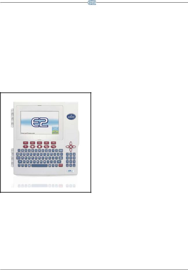
1 Introduction
The E2 controller is a microprocessor-based control system designed to provide complete control of compressor groups, condensers, refrigerated cases, and other components related to refrigeration and building control. The E2 is the controlling component of a three-network config-
uration (RS485 I/O, Echelon® Lonworks™ Networks, and Ethernet) that includes input and output communication boards, remote communication software, and a variety of sensors, probes, and transducers.
The E2 efficiently operates all systems that support refrigeration (including compressor racks and condensers) and other components not directly related to refrigeration control, such as HVAC systems, anti-sweat heaters, and sensor control modules.
Figure 1-1 - E2 Controller
1.1 The E2 Refrigeration
Controller (RX)
The E2 RX is available in three models: the RX-300, RX-400, and RX-100. The E2 RX-300 is capable of controlling a single refrigeration system (including one condenser and up to four suction groups). The E2 RX-400 is capable of controlling two separate refrigeration systems (including two condensers and up to four suction groups). The RX-100 is a low-cost alternative to the RX-300 with
fewer capabilities and a monochrome display.
The E2 RX is primarily designed to control temperature and defrost in refrigerated cases using either direct control (connected to the E2 via I/O boards or ESR8 lineup control boards) or by using CC-100 case control boards (connected via the LonWorks Network).
Table 1-1 shows the differences between capabilities for the RX-300 and RX-400.
Capabilities |
RX- |
RX- |
RX- |
|
100 |
300 |
400 |
||
|
||||
|
|
|
|
|
Analog Combiner |
0 |
128 |
128 |
|
|
|
|
|
|
Analog Import Point |
0 |
64 |
64 |
|
|
|
|
|
|
Analog Sensor Control |
24 |
64 |
72 |
|
|
|
|
|
|
Anti-Sweat |
8 |
16 |
64 |
|
|
|
|
|
|
Case Control Circuit |
0 |
48 |
64 |
|
|
|
|
|
|
CC100 Case Suction |
0 |
99 |
99 |
|
|
|
|
|
|
CC100 Liquid Control |
0 |
99 |
99 |
|
|
|
|
|
|
CCB |
0 |
99 |
99 |
|
|
|
|
|
|
Condenser |
1 |
1 |
2 |
|
|
|
|
|
|
Control Link ACC |
16 |
63 |
63 |
|
|
|
|
|
|
Control Link Case Disp |
0 |
99 |
99 |
|
|
|
|
|
|
Control Link RSC |
0 |
99 |
99 |
|
|
|
|
|
|
CS100 Ckt Suction |
0 |
99 |
99 |
|
|
|
|
|
|
CT Drive |
0 |
16 |
16 |
|
|
|
|
|
|
Digital Combiner |
0 |
128 |
128 |
|
|
|
|
|
|
Digital Sensor Control |
24 |
64 |
72 |
|
|
|
|
|
|
Discus |
0 |
63 |
63 |
|
|
|
|
|
|
E2 Alarm Panel |
7 |
7 |
7 |
|
|
|
|
|
|
Energy Meter |
30 |
30 |
30 |
|
|
|
|
|
|
Enhanced Suction Group |
4 |
4 |
4 |
|
|
|
|
|
Table 1-1 - RX-100, RX-300, and RX-400 Comparison
The E2 Refrigeration Controller (RX) |
Introduction • 1-1 |

Capabilities |
RX- |
RX- |
RX- |
|
100 |
300 |
400 |
||
|
||||
|
|
|
|
|
ESR8 ESR Control |
0 |
99 |
99 |
|
|
|
|
|
|
Flexible Combiner |
64 |
128 |
128 |
|
|
|
|
|
|
Heat/Cool Control |
0 |
16 |
16 |
|
|
|
|
|
|
Holiday Schedule |
4 |
64 |
64 |
|
|
|
|
|
|
Impulse |
0 |
48 |
64 |
|
|
|
|
|
|
Infrared Leak Detection |
1 |
16 |
16 |
|
|
|
|
|
|
K5 Ref Scroll |
0 |
31 |
31 |
|
|
|
|
|
|
Logging Group |
8 |
32 |
32 |
|
|
|
|
|
|
Loop/Sequence Control |
4 |
16 |
24 |
|
|
|
|
|
|
Modular Chiller Control |
0 |
1 |
2 |
|
|
|
|
|
|
MultiFlex ESR |
0 |
31 |
31 |
|
|
|
|
|
|
MRLDS |
24 |
24 |
24 |
|
|
|
|
|
|
Performance Alert |
0 |
63 |
63 |
|
|
|
|
|
|
Power Monitoring |
1 |
16 |
16 |
|
|
|
|
|
|
Pulse Accumulator |
0 |
16 |
16 |
|
|
|
|
|
|
RMS Asset |
99 |
99 |
99 |
|
|
|
|
|
|
Standard Circuit |
48 |
48 |
64 |
|
|
|
|
|
|
Suction Group |
4 |
4 |
4 |
|
|
|
|
|
|
TD Condenser Fan Con- |
4 |
64 |
64 |
|
trol |
|
|
|
|
|
|
|
|
|
TD3 Controller |
0 |
99 |
99 |
|
|
|
|
|
|
Time Schedule |
4 |
64 |
64 |
|
|
|
|
|
Table 1-1 - RX-100, RX-300, and RX-400 Comparison
1.2 The E2 Building
Controller (BX)
The counterpart to the E2 RX is the E2 BX, which controls HVAC systems for low-rise retail, industrial, and commercial buildings. The BX’s primary function is to provide energy-efficient control of air handling units
(AHUs), rooftop units (RTUs), and other systems related to environment control. In addition, the BX provides extensive sensor control, logging, and graphing features that allow the user to view accurate real-time information about system conditions. The BX is equipped with many power monitoring and demand control features that give you the information you need to keep your site’s energy consumption low.
The E2 BX is available in two models: the BX-300 and BX-400. The only significant difference between the E2 BX-300 and the E2 BX-400 is the total number of building control devices that may be operated by a single controller. Table 1-2 shows the differences between capabilities for the BX-300 and BX-400.
Capabilities |
BX-300 |
BX-400 |
|
|
|
Advanced Rooftop |
32 |
32 |
Control |
|
|
|
|
|
AHU |
6 |
8 |
|
|
|
Analog Combiner |
128 |
128 |
|
|
|
Analog Import Point |
64 |
64 |
|
|
|
Analog Sensor Control |
64 |
72 |
|
|
|
Anti-Sweat |
16 |
48 |
|
|
|
Control Link ACC |
16 |
48 |
|
|
|
Control Link Case Disp |
99 |
99 |
|
|
|
Control Link RSC |
99 |
99 |
|
|
|
Copeland CoreSense |
31 |
31 |
Communications |
|
|
|
|
|
CT Drive |
16 |
16 |
|
|
|
Demand Control |
2 |
2 |
|
|
|
Digital Combiner |
128 |
128 |
|
|
|
Digital Sensor Control |
64 |
72 |
|
|
|
E2 Alarm Panel |
7 |
7 |
|
|
|
Energy Meter |
30 |
30 |
|
|
|
Flexible Combiner |
128 |
128 |
|
|
|
Heat/Cool Control |
16 |
32 |
|
|
|
Table 1-2 - BX-300 vs. BX-400 Comparison
1-2 • E2 RX/BX/CX I&O Manual |
026-1614 Rev 4 5-JAN-2013 |

|
|
|
|
|
|
|
|
|
|
|
|
|
|
|
Capabilities |
BX-300 |
BX-400 |
|
|
|
|
|
|
|
Holiday Schedule |
64 |
64 |
|
|
|
|
|
|
|
HVAC Zone |
32 |
40 |
|
|
|
|
|
|
|
Infrared Leak Detec- |
16 |
16 |
|
|
tion |
|
|
|
|
|
|
|
|
|
Lighting Control |
24 |
48 |
|
|
|
|
|
|
|
Logging Group |
32 |
32 |
|
|
|
|
|
|
|
Loop/Sequence Control |
16 |
28 |
|
|
|
|
|
|
|
MRLDS |
24 |
24 |
|
|
|
|
|
|
|
Power Monitoring |
32 |
64 |
|
|
|
|
|
|
|
Pulse Accumulator |
32 |
64 |
|
|
|
|
|
|
|
RCB/RCB-P Controller |
64 |
64 |
|
|
|
|
|
|
|
RMS Asset |
99 |
99 |
|
|
|
|
|
|
|
TD Condenser Fan |
16 |
28 |
|
|
Control |
|
|
|
|
|
|
|
|
|
Time Schedule |
64 |
64 |
|
|
|
|
|
|
|
Table 1-2 - BX-300 vs. BX-400 Comparison
1.3 The E2 Convenience
Store Controller (CX)
The E2 CX controls HVAC, lighting, and refrigeration systems for convenience store and small-box retail facilities. The CX’s primary function is to provide energy-effi- cient control of rooftop units as well as refrigeration and defrost control of display cases and walk-in boxes. In addition, the CX provides extensive sensor control, logging, and graphing features that allow the user to view accurate real-time information about system conditions. The CX is equipped with many power monitoring and demand control features that give you the information you need to keep your site’s energy consumption low.
The E2 CX is available in three models: the CX-300, CX-400, and CX-100. The only significant difference between the E2 CX-300 and the E2 CX-400 is the amount of C-Store equipment that may be operated by a single controller. The CX-100 is a low-cost alternative to the CX300 with fewer capabilities and a monochrome display. Table 1-3 shows the differences between capabilities for
the CX-300 and CX-400.
Capabilities |
CX- |
CX- |
CX- |
|
100 |
300 |
400 |
||
|
||||
|
|
|
|
|
Advanced Rooftop |
0 |
32 |
32 |
|
Control |
|
|
|
|
|
|
|
|
|
AHU |
4 |
6 |
8 |
|
|
|
|
|
|
Analog Combiner |
64 |
128 |
128 |
|
|
|
|
|
|
Analog Sensor Control |
12 |
24 |
48 |
|
|
|
|
|
|
Anti-Sweat |
4 |
8 |
16 |
|
|
|
|
|
|
Case Control Circuit |
0 |
12 |
24 |
|
|
|
|
|
|
CC100 Case Suction |
0 |
99 |
99 |
|
|
|
|
|
|
CC100 Liquid Control |
0 |
99 |
99 |
|
|
|
|
|
|
CCB |
0 |
99 |
99 |
|
|
|
|
|
|
Condenser |
0 |
0 |
1 |
|
|
|
|
|
|
Control Link ACC |
8 |
16 |
16 |
|
|
|
|
|
|
Control Link Case Disp |
6 |
99 |
99 |
|
|
|
|
|
|
Control Link RSC |
10 |
99 |
99 |
|
|
|
|
|
|
Copeland CoreSense |
0 |
31 |
31 |
|
Communication |
|
|
|
|
|
|
|
|
|
CS100 Ckt Suction |
0 |
99 |
99 |
|
|
|
|
|
|
CT Drive |
0 |
16 |
16 |
|
|
|
|
|
|
Demand Control |
1 |
1 |
1 |
|
|
|
|
|
|
Digital Combiner |
64 |
128 |
128 |
|
|
|
|
|
|
Digital Sensor Control |
12 |
24 |
48 |
|
|
|
|
|
|
Discus |
0 |
0 |
63 |
|
|
|
|
|
|
E2 Alarm Panel |
7 |
7 |
7 |
|
|
|
|
|
|
Energy Meter |
30 |
30 |
30 |
|
|
|
|
|
|
Enhanced Suction |
0 |
0 |
4 |
|
Group |
|
|
|
|
|
|
|
|
Table 1-3 - CX-100, CX-300, and CX-400 Comparison
The E2 Convenience Store Controller (CX) |
Introduction • 1-3 |
Capabilities |
CX- |
CX- |
CX- |
|
100 |
300 |
400 |
||
|
||||
|
|
|
|
|
ESR8 ESR Control |
0 |
99 |
99 |
|
|
|
|
|
|
Flexible Combiner |
64 |
128 |
128 |
|
|
|
|
|
|
Heat/Cool Control |
4 |
6 |
8 |
|
|
|
|
|
|
Holiday Schedule |
8 |
16 |
32 |
|
|
|
|
|
|
HVAC Zone |
4 |
6 |
12 |
|
|
|
|
|
|
Infrared Leak Detec- |
1 |
16 |
16 |
|
tion |
|
|
|
|
|
|
|
|
|
Irrigation |
2 |
2 |
2 |
|
|
|
|
|
|
Lighting Control |
6 |
24 |
48 |
|
|
|
|
|
|
K5 Ref Scroll |
0 |
0 |
31 |
|
|
|
|
|
|
Logging Group |
8 |
32 |
32 |
|
|
|
|
|
|
Loop/Sequence Control |
8 |
16 |
28 |
|
|
|
|
|
|
MultiFlex ESR |
0 |
31 |
31 |
|
|
|
|
|
|
MRLDS |
24 |
24 |
24 |
|
|
|
|
|
|
Performance Alert |
0 |
0 |
63 |
|
|
|
|
|
|
Power Monitoring |
2 |
8 |
16 |
|
|
|
|
|
|
Pulse Accumulator |
4 |
8 |
16 |
|
|
|
|
|
|
RCB/RCB-P Controller |
0 |
32 |
32 |
|
|
|
|
|
|
RMS Asset |
99 |
99 |
99 |
|
|
|
|
|
|
Standard Circuit |
6 |
12 |
32 |
|
|
|
|
|
|
Suction Group |
0 |
0 |
4 |
|
|
|
|
|
|
TD Condenser Fan |
8 |
16 |
28 |
|
Control |
|
|
|
|
|
|
|
|
|
TD3 Controller |
0 |
99 |
99 |
|
|
|
|
|
|
Time Schedule |
8 |
16 |
32 |
|
|
|
|
|
Table 1-3 - CX-100, CX-300, and CX-400 Comparison
1.4Networking Overview
1.4.1E2 I/O Network
Most of the general purpose input and output communications devices required by the E2 to control refrigeration systems are connected to the E2 via the I/O Network. The I/O Network is a simple RS485 three-wire connection that allows data interchange between input boards (which read sensor values and digital closures), output boards (which carry out commands from E2’s control applications), and the E2 itself.
The I/O Network is the same thing as the COM A and COM D Networks found on Emerson Retail Solutions’ previous generation of controllers, REFLECS. This allows current owners of Emerson Retail Solutions’ Refrigeration Monitor and Control (RMC) or Refrigeration Monitor and Case Control (RMCC) controllers to easily retrofit with an E2 RX without need for re-wiring.
E2 RX |
E2 |
|
|
|
|
|
|
|
|
|
|
|
|
|
|
|
|
|
|
|
|
|
|
|
|
|
|
|
|
|
|
|
|
|
|
|
|
|
|
|
|
|
|
|
|
|
|
|
|
|
|
|
|
|
|
|
|
|
|
|
|
|
|
|
|
|
|
|
|
|
|
|
|
|
|
|
|
|
|
|
|
|
|
|
|
|
|
|
|
|
|
|
|
|
|
|
|
|
|
|
|
|
|
|
|
|
|
|
|
|
|
|
|
|
|
|
|
|
|
|
|
|
|
|
|
|
|
|
|
|
|
|
|
|
|
|
|
|
|
|
|
|
|
|
|
|
|
|
|
|
|
|
|
|
|
|
|
|
|
|
|
|
|
|
|
|
|
|
|
|
|
|
|
|
|
|
|
|
|
|
|
|
|
|
|
|
|
|
|
|
|
|
|
|
|
|
|
|
|
|
|
|
|
|
|
|
|
|
|
|
|
|
|
|
|
|
|
|
|
|
|
|
|
|
|
|
|
|
|
|
|
|
|
|
|
|
|
|
|
|
|
|
|
|
|
|
|
|
|
|
|
|
|
|
|
|
|
|
|
|
|
|
|
|
|
|
|
|
|
|
|
|
|
|
|
|
|
|
|
|
|
|
|
|
|
|
|
|
|
|
|
|
|
|
|
|
|
|
|
|
|
|
|
|
|
|
|
|
|
|
|
|
|
|
|
|
|
|
|
|
|
|
|
|
|
|
|
|
|
|
|
|
|
|
|
|
|
|
|
|
|
|
|
|
|
|
|
|
|
|
|
|
|
|
|
|
|
|
|
|
|
|
|
|
|
|
|
|
|
|
|
|
|
|
|
|
|
|
|
|
|
|
|
|
|
|
|
|
|
|
|
|
|
|
|
|
|
|
|
|
|
|
|
|
|
|
|
|
|
|
|
|
|
|
|
|
|
|
|
|
|
|
|
|
|
|
|
|
|
|
|
|
|
|
|
|
|
|
|
|
|
|
|
|
|
|
|
|
|
|
|
|
|
|
|
|
|
|
|
|
|
|
|
|
|
|
|
|
|
|
|
|
|
|
|
|
|
|
|
|
|
|
|
|
|
|
|
|
|
|
|
|
|
|
|
|
|
|
|
|
|
|
|
|
|
|
|
|
|
|
|
|
|
|
|
|
|
|
|
|
|
|
|
|
|
|
|
|
|
|
|
|
|
|
|
|
|
|
|
|
|
|
|
|
|
|
|
|
|
|
|
|
|
|
|
|
|
|
|
|
|
|
|
|
|
|
|
|
|
|
|
|
|
|
|
|
|
|
|
|
|
|
|
|
|
|
|
|
|
|
|
|
|
|
|
|
|
|
|
|
|
|
|
|
|
|
|
|
|
|
|
|
|
|
|
|
|
|
|
|
|
|
|
|
|
|
|
|
|
|
|
|
|
|
|
|
|
|
|
|
|
|
|
|
|
|
|
MultiFlex |
|
|
|
CS-100 |
|
|
|
|
|
|
|
|
|
|
|
|
|
|
|
|
|
|
|
|
|
|
|
|
|
|
|
|
MultiFlex |
|
|||||||||||||||||||||||||||||
|
|
|
|
|
|
|
|
|
I/O |
|
|
CS-100 |
|
|
|
|
|
|
|
|
|
|
|
|
|
|
|
|
|
|
|
|
|
|
|
|
|
|
|
|
|
|
|
|
I/O |
|
||||||||||||||||||||||||
|
|
|
|
|
|
|
MultiFlex |
|
|
CC-100 |
|
|
|
|
|
|
|
|
|
|
|
|
|
|
|
|
|
|
|
|
|
|
|
|
|
|
|
MultiFlex |
|
|||||||||||||||||||||||||||||||
|
|
|
|
|
|
|
|
|
|
|
|
|
|
|
|
|
|
|
|
|
|
|
|
|
|
|
|
|
|
|
|
|
|
|
|
|||||||||||||||||||||||||||||||||||
|
|
|
|
|
|
|
|
|
I/O |
|
|
CC-100 |
|
|
|
|
|
|
|
|
|
|
|
|
|
|
|
|
|
|
|
|
|
|
|
|
|
|
|
|
|
|
|
I/O |
|
|||||||||||||||||||||||||
|
|
|
|
|
|
|
MultiFlex |
|
|
CC-100 |
|
|
|
|
|
|
|
|
|
|
|
|
|
|
|
|
|
|
|
|
|
|
|
|
|
|
|
MultiFlex |
|
|||||||||||||||||||||||||||||||
|
|
|
|
|
|
|
|
|
|
|
|
|
|
|
|
|
|
|
|
|
|
|
|
|
|
|
|
|
|
|
|
|
|
|
|
|
|
|
|
|
|
|
|
|
|
|||||||||||||||||||||||||
|
|
|
|
|
|
|
|
|
I/O |
|
|
|
|
|
|
|
|
|
|
|
|
|
|
|
|
|
|
|
|
|
|
|
|
|
|
|
|
|
|
|
|
|
|
|
|
|
|
|
|
|
|
I/O |
|
|||||||||||||||||
|
|
|
|
|
|
|
MultiFlex |
|
|
|
|
|
|
|
|
|
|
|
|
|
|
|
|
|
|
|
|
|
|
|
|
|
|
|
|
|
|
|
|
|
|
|
|
|
|
|
MultiFlex |
|
||||||||||||||||||||||
|
|
|
|
|
|
|
|
|
I/O |
|
|
|
|
|
|
|
|
|
|
|
|
|
|
|
|
|
|
|
|
|
|
|
|
|
|
|
|
|
|
|
|
|
|
|
|
|
|
|
|
|
|
I/O |
|
|||||||||||||||||
|
|
|
|
|
|
|
|
|
|
|
|
|
|
|
|
|
|
|
|
|
|
|
|
|
|
|
|
|
|
|
|
|
|
|
|
|
|
|
|
|
|
|
|
|
|
|
|
|
|
|
|
|
|
|
|
|
|
|
|
|
|
|
|
|
|
|
|
|
|
|
|
|
|
|
|
|
|
|
|
|
|
|
|
|
|
|
|
|
|
|
|
|
|
|
|
|
|
|
|
|
|
|
|
|
|
|
|
|
|
|
|
|
|
|
|
|
|
|
|
|
|
|
|
|
|
|
|
|
|
|
|
|
|
|
|
|
|
|
|
|
|
E2 RX & BX
RS485 I/O NETWORKS
Figure 1-2 - E2 RX/BX I/O Network Diagram
Figure 1-2 shows the peripherals that make up the I/O Network:
•MultiFlex - The MultiFlex line of control system boards provide a wide variety of input, output, and smart control solutions, all of which are based on a single universal hardware platform.
•8ROSMT - Relay output board - activates and deactivates up to eight devices.
1-4 • E2 RX/BX/CX I&O Manual |
026-1614 Rev 4 5-JAN-2013 |
1.4.2 The E2 Echelon Lonworks Network
The E2 is also compatible with a network platform called Lonworks. This is most commonly referred to as “the Echelon Network,” after the company who invented the platform, the Echelon Corporation.
In general, peripherals with control functions — such as case controllers, rooftop HVAC controllers, and other E2 RX and BX units — are interconnected on the Echelon Network. These controllers do most of their own computation and system control, but they communicate with other E2s to provide logging, alarm control, and other functions. In addition to these, Emerson Retail Solutions also offers Echelon-compatible input and output boards similar to those available for the RS485 Network.
E2 RX |
E2 |
|
|
|
|
|
|
|
|
|
|
|
|
|
|
|
|
|
|
|
|
|
|
|
|
|
|
|
|
|
|
|
|
|
|
|
|
|
|
|
|
|
|
|
|
|
|
|
|
|
|
|
|
|
|
|
|
|
|
|
|
|
|
|
|
|
|
|
|
|
|
|
|
|
|
|
|
|
|
|
|
|
|
|
|
|
|
|
|
|
|
|
|
|
|
|
|
|
|
|
|
|
|
|
|
|
|
|
|
|
|
|
|
|
|
|
|
|
|
|
|
|
|
|
|
|
|
|
|
|
|
|
|
|
|
|
|
|
|
|
|
|
|
|
|
|
|
|
|
|
|
|
|
|
|
|
|
|
|
|
|
|
|
|
|
|
|
|
|
|
|
|
|
|
|
|
|
|
|
|
|
|
|
|
|
|
|
|
|
|
|
|
|
|
|
|
|
|
|
|
|
|
|
|
|
|
|
|
|
|
|
|
|
|
|
|
|
|
|
|
|
|
|
|
|
|
|
|
|
|
|
|
|
|
|
|
|
|
|
|
|
|
|
|
|
|
|
|
|
|
|
|
|
|
|
|
|
|
|
|
|
|
|
|
|
|
|
|
|
|
|
|
|
|
|
|
|
|
|
|
|
|
|
|
|
|
|
|
|
|
|
|
|
|
|
|
|
|
|
|
|
|
|
|
|
|
|
|
|
|
|
|
|
|
|
|
|
|
|
|
|
|
|
|
|
|
|
|
|
|
|
|
|
|
|
|
|
|
|
|
|
|
|
|
|
|
|
|
|
|
|
|
|
|
|
|
|
|
|
|
|
|
|
|
|
|
|
|
|
|
|
|
|
|
|
|
|
|
|
|
|
|
|
|
|
|
|
|
|
|
|
|
|
|
|
|
|
|
|
|
|
|
|
|
|
|
|
|
|
|
|
|
|
|
|
|
|
|
|
|
|
|
|
|
|
|
|
|
|
|
|
|
|
|
|
|
|
|
|
|
|
|
|
|
|
|
|
|
|
|
|
|
|
|
|
|
|
|
|
|
|
|
|
|
|
|
|
|
|
|
|
|
|
|
|
|
|
|
|
|
|
|
|
|
|
|
|
|
|
|
|
|
|
|
|
|
|
|
|
|
|
|
|
|
|
|
|
|
|
|
|
|
|
|
|
|
|
|
|
|
|
|
|
|
|
|
|
|
|
|
|
|
|
|
|
|
|
|
|
|
|
|
|
|
|
|
|
|
|
|
|
|
|
|
|
|
|
|
|
|
|
|
|
|
|
|
|
|
|
|
|
|
|
|
|
|
|
|
|
|
|
|
|
|
|
|
|
|
|
|
|
|
|
|
|
|
|
|
|
|
|
|
|
|
|
|
|
|
|
|
|
|
|
|
|
|
|
|
|
|
|
|
|
|
|
|
|
|
|
|
|
|
|
|
|
|
|
CS-100 |
|
|
|
|
|
|
|
|
|
|
|
|
|
|
|
|
|
|
|
|
|
|
|
|
|
|
|
|
|
|
|
|
|
|
|
|
|
|
|
|
|||||||
|
|
|
|
|
|
|
|
|
|
|
|
|
|
|
|
|
|
|
|
|
|
|
|
|
|
|
|
|
|
|
|
|
|
|
|
|
|
|
|
|
|
|
|
|
|
|
|
|
||||||||
|
|
|
|
|
|
|
|
|
|
|
|
|
|
|
|
|
|
|
|
|
|
|
|
|
|
|
|
|
|
|
|
|
|
|
|
|
|
|
|
|
|
|
|
|
|
|
|
|
||||||||
|
|
|
|
|
|
|
|
|
|
|
|
|
|
|
|
|
|
|
|
|
|
|
|
|
|
|
|
|
|
|
|
|
|
|
|
|
|
|
|
|
|
|
|
|
|
|
|
|
||||||||
|
|
|
|
|
|
|
|
|
|
|
|
|
|
|
|
|
|
|
|
|
|
|
|
|
|
|
|
|
|
|
|
|
|
|
|
|
|
|
|
|
|
|
|
|
|
|
|
|
||||||||
|
|
|
|
|
|
|
|
|
|
|
|
|
|
|
|
|
|
|
|
|
|
|
|
|
|
|
|
|
|
|
|
|
|
|
|
|
|
|
|
|
|
|
|
|
|
|
|
|
||||||||
|
|
|
|
|
|
|
|
|
|
|
|
|
|
|
|
|
|
|
|
|
|
|
|
|
|
|
|
|
|
|
|
|
|
|
|
|
|
|
|
|
|
|
|
|
|
|
|
|
||||||||
|
|
|
|
|
|
|
|
|
|
|
|
|
|
|
|
|
|
|
|
|
|
|
|
|
|
|
|
|
|
|
|
|
|
|
|
|
|
|
|
|
|
|
|
|
|
|
|
|
||||||||
|
|
|
|
|
|
|
|
|
|
|
|
|
|
|
|
|
|
|
|
|
|
|
|
|
|
|
|
|
|
|
|
|
|
|
|
|
|
|
|
|
|
|
|
|
|
|
|
|
||||||||
|
|
|
|
|
|
|
|
|
|
|
|
|
|
|
|
|
|
|
|
|
|
|
|
|
|
|
|
|
|
|
|
|
|
|
|
|
|
|
|
|
|
|
|
|
|
|
|
|
||||||||
|
|
|
|
|
|
|
|
|
|
|
|
|
|
|
|
|
|
|
|
|
|
|
|
|
|
|
|
|
|
|
|
|
|
|
|
|
|
|
|
|
|
|
|
|
|
|
|
|
||||||||
|
|
|
|
|
|
|
|
|
|
|
|
|
|
|
|
|
|
|
|
|
|
|
|
|
|
|
|
|
|
|
|
|
|
|
|
|
|
|
|
|
|
|
|
|
|
|
|
|
||||||||
|
|
|
|
|
|
|
|
|
|
|
|
|
|
|
|
|
|
|
|
|
|
|
|
|
|
|
|
|
|
|
|
|
|
|
|
|
|
|
|
|
|
|
|
|
MultiFlex |
|||||||||||
|
|
|
|
|
|
|
|
|
|
|
|
|
|
|
|
|
|
|
|
|
|
|
|
|
|
|
|
|
|
|
|
|
|
|
|
|
|
|||||||||||||||||||
MultiFlex |
|
|
|
|
|
|
|
|
|
|
|
|
|
|
|
|
|
|
|
|
|
|
|
|
|
|
|
|
|
|
|
|
|
|
|
|
|
|
||||||||||||||||||
|
|
|
|
|
|
|
|
|
|
|
|
|
|
|
|
|
|
|
|
|
|
|
|
|
|
|
|
|
|
|
|
|
|
|
|
|||||||||||||||||||||
I/O |
|
|
CS-100 |
|
|
|
|
|
|
|
|
|
|
|
|
|
|
|
|
|
|
|
|
|
|
|
|
|
|
|
|
|
|
|
|
|
|
|
|
|
|
I/O |
||||||||||||||
|
|
|
|
|
|
|
|
|
|
|
|
|
|
|
|
|
|
|
|
|
|
|
|
|
|
|
|
|
|
|
|
|
|
|
|
|
|
|
|
|
|
|
|
|
|
|
|
|
||||||||
|
|
CC-100 |
|
|
|
|
|
|
|
|
|
|
|
|
|
|
|
|
|
|
|
|
|
|
|
|
|
|
|
|
|
|
|
|
|
|
|
|
MultiFlex |
|||||||||||||||||
MultiFlex |
|
|
|
|
|
|
|
|
|
|
|
|
|
|
|
|
|
|
|
|
|
|
|
|
|
|
|
|
|
|
|
|
|
|
|
|
|
|||||||||||||||||||
|
|
|
|
|
|
|
|
|
|
|
|
|
|
|
|
|
|
|
|
|
|
|
|
|
|
|
|
|
|
|
|
|
|
|
|
|||||||||||||||||||||
I/O |
|
|
|
|
|
|
|
|
|
|
|
|
|
|
|
|
|
|
|
|
|
|
|
|
|
|
|
|
|
|
|
|
|
|
|
|
|
|
|
|
|
|
|
|
|
|
|
|
I/O |
|||||||
|
|
|
|
|
|
|
|
|
|
|
|
|
|
|
|
|
|
|
|
|
|
|
|
|
|
|
|
|
|
|
|
|
|
|
|
|
|
|
|
|
|
|
|
|
||||||||||||
CC-100 |
|
|
|
|
|
|
|
|
|
|
|
|
|
|
|
|
|
|
|
|
|
|
|
|
|
|
|
|
|
|
|
|
|
|
|
|
|
|
||||||||||||||||||
|
|
|
|
|
|
|
|
|
|
|
|
|
|
|
|
|
|
|
|
|
|
|
|
|
|
|
|
|
|
|
|
|
|
|
|
|
|
|
||||||||||||||||||
|
|
|
|
|
|
|
|
|
|
|
|
|
|
|
|
|
|
|
|
|
|
|
|
|
|
|
|
|
|
|
|
|
|
|
|
|
|
|
|
|||||||||||||||||
|
|
|
|
|
|
|
|
|
|
|
|
|
|
|
|
|
|
|
|
|
|
|
|
|
|
|
|
|
|
|
|
|
|
|
|
|
|
|
|
|
|
|
|
|
|
|
|
|
|
|
|
|
|
|
|
|
|
|
|
|
|
|
|
|
|
CC-100 |
|
|
|
|
|
|
|
|
|
|
|
|
|
|
|
|
|
|
|
|
|
|
|
|
|
|
|
|
|
|
|
|
|
|
|
MultiFlex |
|||||||||||
MultiFlex |
|
|
|
|
|
|
|
|
|
|
|
|
|
|
|
|
|
|
|
|
|
|
|
|
|
|
|
|
|
|
|
|
|
|
|
|
|
|
|
|
|
|
|
|||||||||||||
|
|
|
|
|
|
|
|
|
|
|
|
|
|
|
|
|
|
|
|
|
|
|
|
|
|
|
|
|
|
|
|
|
|
|
|
|
|
|
|
|
|
|
||||||||||||||
|
|
|
|
|
|
|
|
|
|
|
|
|
|
|
|
|
|
|
|
|
|
|
|
|
|
|
|
|
|
|
|
|
|
|
|
|
|
|
|
|
|
|
||||||||||||||
I/O |
|
|
|
|
|
|
|
|
|
|
|
|
|
|
|
|
|
|
|
|
|
|
|
|
|
|
|
|
|
|
|
|
|
|
|
|
|
|
|
|
|
|
|
|
|
|
I/O |
|||||||||
MultiFlex |
|
|
|
|
|
|
|
|
|
|
|
|
|
|
|
|
|
|
|
|
|
|
|
|
|
|
|
|
|
|
|
|
|
|
|
|
|
|
|
|
|
|
|
MultiFlex |
||||||||||||
I/O |
|
|
|
|
|
|
|
|
|
|
|
|
|
|
|
|
|
|
|
|
|
|
|
|
|
|
|
|
|
|
|
|
|
|
|
|
|
|
|
|
|
|
|
|||||||||||||
|
|
|
|
|
|
|
|
|
|
|
|
|
|
|
|
|
|
|
|
|
|
|
|
|
|
|
|
|
|
|
|
|
|
|
|
|
|
|
|
|
|
|
|
|
|
I/O |
||||||||||
E2 RX & BX
ECHELON NETWORKS
Figure 1-3 - E2 RX Echelon Network Diagram
Figure 1-3 shows the E2 RX peripherals that communicate across the Echelon Network:
•CC-100 - Case control board - controls all lights, fans, defrost, and refrigeration for a single case. The CC-100 controls pulse or stepper valves to provide precise evaporator control, resulting in better temperature maintenance and energy efficiency.
•ESR8 - Evaporator stepper regulator - the analog outputs on this board allow the E2 to control circuit temperature in up to eight circuits using suction-
side mounted electronic evaporator pressure regulators (EEPRs).
•TD3 - Temperature display - has three inputs that monitor case temperature, product temperature and defrost status.
•Third Party Echelon Devices - Echelon® LONMARK® devices communicate with E2 through its “Open Echelon” networking feature, and require a license key and a description file that is loaded into the E2 that enables communication.
1.4.3 Interconnection With Other
E2s
In large installations where more than one refrigeration
system is present, or where E2s are controlling both refrigeration and building HVAC systems in the same site, the E2s share information with each other across either the Echelon Network or via Ethernet.
Echelon Box-To-Box |
ECHELON CABLE (daisy chain) |
Ethernet Box-To-Box |
CAT5 CABLE |
Switch |
Figure 1-4 - E2 RX/BX Network |
Networking Overview |
Introduction • 1-5 |

1.5 Documentation
Overview
The E2 RX and BX controllers are among the most versatile and customizable control system products available on the market. Because of the enhanced capabilities of the E2s, programming, installation, and operation of E2 and its accompanying peripherals are supported by several different Emerson Retail Solutions publications. All of the publications listed below can be ordered by contacting Emerson Retail Solutions:
•E2 Installation and Operation Manual for RX Refrigeration, BX HVAC, and CX Convenience Store Controllers (026-1610) - The manual you are currently reading. The Installation and Operation Manual covers hardware installation, network setup, and important operator functions such as viewing status screens or logs, and performing manual defrosts.
The Quick Start section (Section 10) is designed to guide you quickly through setup of the most simple and vital refrigeration control applications (such as suction groups and condensers). More detailed information is included in the online help.
•Router and Repeater Installation Guide (P/N 0261605) - If you have a large site with 64 or more devices on the Echelon Network, you might require the use of a router or repeater to properly set up your Echelon Network. The Router and Repeater Installation Guide will help you determine when a router or repeater should be used, how and where to set it up, and how to configure the E2(s) on the network to interact with the router or repeater.
•Emerson Retail Solutions Product Technical Sheet Binder (P/N 026-1904) - The product sheet binder gives important installation information about sensors, transducers, thermostats, and other essential items that are a part of every Emerson Retail Solutions control network. The product sheet binder is not necessary for field installation instructions; however, it may be a useful reference for contractors and OEMs who require more information about a specific peripheral.
•MultiFlex ESR Installation and Operation Manual (P/N 026-1720) - From general information to details on mounting, wiring, and heat dissipation, the MultiFlex ESR manual provides the information you need to install and operate the MultiFlex ESR board, in addition to valuable information on software setup and valve control.
•MultiFlex I/O Board Installation and Operation Manual (P/N 026-1704) - Installation and operation manual for the MultiFlex 16 and all versions of the MultiFlex combination input/output board, excluding unit controllers such as the CUB and RTU.
•MultiFlex CUB/CUB II Condensing Unit Board Installation and Operation Manual (P/N 0261705) - Installation and operation manual for the MultiFlex CUB (old style) and the MultiFlex CUBII family, which includes the CUB-II and CUB-TD.
•MultiFlex RTU Rooftop Controller Installation and Operation Manual (P/N 026-1706) - Installation and operation guide for the MultiFlex RTU (replacement for ARTC).
•MultiFlex RCB Rooftop Controller Installation and Operation Manual (P/N 026-1707) - An improved version of the MultiFlex RTU, the RCB has 16 fully configurable analog and digital input points. The RCB also has four analog outputs for use in controlling variable speed fans, economizers, or modulating heating and/or cooling valves. The RCB also features a more sophisticated HHT interface and updated algorithms for controlling heating, cooling, dehumidification, and air quality. Refer to this manual for more information on the MultiFlex RCB Rooftop Controller.
•E2 User’s Manual Supplement for Flexible Combiner Programming (P/N 026-1620) - The Flexible Combiner application is an advanced I/O control program used to combine multiple analog and digital input values using programmed equations similar to those used in spreadsheets, and is a new feature of E2 versions 2.20 and above. Refer to this manual for more information on the Flexible Combiner application.
•Facility Status Display (FSD) Installation and Operation Manual (P/N 026-1400) - The FSD reports alarm information and more, (such as temperatures, occupancy, case status, and setpoints) and provides a centralized device for store personnel to review information by communicating with the E2 via Ethernet connectivity (minimum E2 firmware rev. 2.68F01). Refer to this manual for more information on the Status Display application.
•Square D Smart Breaker Control Manual (P/N 026-1711) - The Smart Breaker products are designed to allow the Emerson Retail Solutions family of site controllers to command control panels (minimum E2 firmware rev. 2.71F01). A breaker panel generally consists of a series of cir-
1-6 • E2 RX/BX/CX I&O Manual |
026-1614 Rev 4 5-JAN-2013 |

cuit breakers that are flipped from OFF to ON and from ON to OFF by commands sent from E2 through MODBUS or a Square D Smart Breaker Gateway board. Refer to this manual for more information on the Square D Breaker Panel application.
•Eaton Breaker Control Manual (P/N 026-1709) -
E2 can communicate directly with Eaton's Breaker Control Bus (BCB) modules. Communication with the E2 (minimum E2 firmware rev. 2.82) will enable users to access features such as Time Schedules, Enhanced Lighting, and Logging, with the added capabilities of dial-out on failure and offsite remote connection, specifically with UltraSite32 and Site Manager to the breaker panel. The Eaton Breaker Panel controller is a licensed application available in the E2 300 and 400 model controllers. Refer to this manual for more information on the Square D Breaker Panel application.
•Energy Meter Manual (P/N 026-1726) - The Energy Meter provides a solution for measuring energy data with a single device. Inputs include Control Power, CT, and 3-phase voltage. The Energy Meter supports multiple output options, including solid state relay contacts, Modbus (with or without data logging), and pulse. The LCD screen on the faceplate allows instant output viewing.
•iPro DAC (P/N 026-1727) - The iPro DAC is a packaged HVAC control board for use either as a stand-alone controller or in zone control applications using a Emerson Retail Solutions E2 BX building control system. The iPro DAC is capable of controlling heat and cool stages, fans, humidification and dehumidification devices and economizers using on-board I/O and control algorithms, as well as monitor and interact with other building control systems and peripherals (such as smoke alarms and CO2 sensors).
•MRLDS (P/N 026-1307) - Modular Refrigerant Leak Detection Sensor (MRLDS) continuously monitors for low levels of refrigerants most commonly used in commercial refrigeration systems. The MRLDS communicates with the E2 controller via MODBUS. The E2 provides an interface while the MRLDS will provide the leak monitoring functionality.
1.6 On-Line Help System
Overview
The E2 On-Line Help is the primary source frontpanel/interface users will have to consult when seeking instruction on properties, screens, menus, and troubleshooting of hardware/software problems. The on-line help topics are designed to minimize the time the user would otherwise have to spend searching through the manual to
find information. Press + keys to open the General Help menu.
To use on-line help from any screen in the E2 front panel interface, simply press the E2’s permanent Helpkey. This opens a pop-up window containing either information about the screen or menu you are currently on, or information about the input, output, or setpoint you have highlighted with the cursor (if available). After the Help key has been pressed, will open the General Help menu containing Troubleshooting options.
1.7Software Licensing
Some applications in the E2 are available only when activated with a unique license key that is obtained through Emerson Retail Solutions. Software licensing (see
Section 10.15, License Management) allows the user to activate certain features in the E2, such as Web Services and third-party controllers. Call your Emerson Retail Solutions sales representative at 770-425-2724 for more information about software licensing.
On-Line Help System Overview |
Introduction • 1-7 |
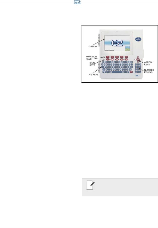
2 Hardware Overview
This section gives an overview of the E2, the hardware, and how it communicates across the I/O and Echelon Networks to control an entire system.
2.1E2 Hardware
The E2 controller is programmed to monitor and command all aspects of a refrigeration or building environmental control system. The E2 uses both an RS485 I/O Network and a LonWorks Network to gather data from input devices, communicate with other E2s, and activate or deactivate loads.
In general, an E2 control network will consist of the following components:
1.E2 - The “brain” of the control network, which performs all necessary computations and sends commands to the output devices that control the system.
2.Input Boards - Transfer readings to the E2.
3.Output Boards - Banks of relays, digital pulse outputs, or analog outputs, which the E2 may use to control loads.
4.Smart Boards - Boards such as case controllers (for refrigeration) or rooftop controllers (for building control) that perform control functions for an individual case or rooftop unit, and send the data to the E2 for logging and alarm purposes.
5.Modem - For remote communication via phone, if necessary.
6.Network Wiring - Wiring that connects the E2 to other E2s, and all the input, output, and smart boards.
7.Sensors and Loads - The “eyes” and “hands” of the control network. Sensors “see” what needs to be controlled on the network, and Loads are what can be controlled, or more specifically, be turned on and off, such as compressors, condensers, lights, and fans.
Figure 2-1 - E2 Front Panel
Dimensions |
Standard Mount: |
|
9.06” W x 12.06” H x 3.75” D |
|
|
|
Recessed Mount: |
|
9.06” W x 10.56” H x 2.0” D |
|
|
|
Base: |
|
10.56” W x 10.56” H x 3.75” D |
|
|
Operating |
-40°F to 149°F (-40°C to 65°C) |
Temp |
|
Storage Temp |
-40°F to 158°F (-40°C to 70°C) |
|
|
Operating |
5% - 95% RH non-condensing at |
Humidity |
90°F |
|
|
Storage |
5% - 100% RH |
Humidity |
|
|
|
Power |
24 VAC ±20%, 50/60 Hz, Class 2 |
|
|
VA Load |
50 |
|
|
Table 2-1 - E2 Specifications
NOTE: Contact Emerson Emerson Retail Solutions Customer Service at 770-425-2724 for E2 controller part numbers and model de-
scriptions.
E2 Hardware |
Hardware Overview • 2-1 |

|
|
|
|
|
|
|
|
2.1.1 E2 Main Processor Board |
|
2.1.3 E2 Keypad |
|
(CPU) |
|
|
|
|
|
|
|
|
|
|
|
Figure 2-2 - E2 CPU
The E2 CPU or main processor board (Figure 2-2) contains the CPU, Ethernet port, and memory used for logging. The coin battery for the E2 is located on this board and protects log and alarm data during power loss. The main processor board connects to the PIB via a ribbon cable. The RXand CX-100 versions support monochrome display only. For optimum viewing, backlight and contrast adjusts are available for customizing the monochrome display depending on the user’s needs.
2.1.2 E2 Processor Interface Board (PIB)
Figure 2-3 - E2 PIB
The E2 Processor Interface Board (PIB) interfaces the power and most all communications with the main processor board, and contains all field wiring connections. The PIB allows you to connect an external keyboard, accessory cards, and an external computer. All RS485 connectors are located on the PIB.
Figure 2-4 - E2 Keyboard
The E2 has a QWERTY style keyboard layout with two rows of function keys. The first row ( - ) is comprised of screen-specific function keys, and the second row has designated icon keys. The five icon keys are Help , Alarms , Home , Menu , and Back .
2.1.4LEDs
The PIB, main processor board, and keyboard (located behind the main board) LEDs can be used to determine the status of normal operating parameters for the unit.
PIB LEDs |
Status |
|
|
Green (14) |
ON: Power is being applied to the |
|
PIB |
Yellow (RX1) |
ON: Communication is being re- |
|
ceived on RS485 Port 1A |
Yellow (RX2) |
ON: Communication is being re- |
|
ceived on RS485 Port 1B |
Red (TX) |
ON: Communication is being sent on |
|
RS485 Port 1A and 1B |
Table 2-2 - PIB LED’s Status
2-2 • E2 RX/BX/CX I&O Manual |
026-1614 Rev 4 5-JAN-2013 |
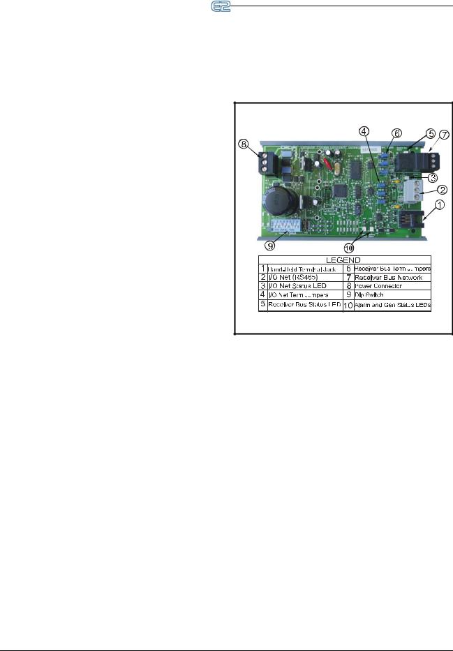
|
|
|
|
|
|
|
|
|
|
|
|
|
|
|
Main Board |
Status |
|
|
|
(CPU) LEDs |
|
|
|
|
|
|
|
|
|
Green |
1 blink every two seconds (1 second |
|
|
|
(D1 General |
ON, 1 second OFF): Main board is |
|
|
|
Status LED for |
operating normally. |
|
|
|
E2 and Blank |
Solid ON: E2 is booting up. |
|
|
|
Face E2) |
Faster blinks per second: Indicates an |
|
|
|
|
|
|
|
|
|
error condition with the hardware or |
|
|
|
|
firmware. |
|
|
|
Green |
ON: E2 is booting up. |
|
|
|
(D18 Boot Sta- |
|
|
|
|
tus LED) |
|
|
|
|
Table 2-3 - Main Board (CPU) LED’s Status |
|
|
|
|
|
|
|
|
|
Keyboard |
Status |
|
|
|
LED |
|
|
|
|
|
|
|
|
|
Green (D5 |
1 blink every two seconds (1 second |
|
|
|
General Status |
ON, 1 second OFF): Status is nor- |
|
|
|
LED) |
mal. |
|
|
|
|
4 blinks per second: A flash and/or |
|
|
|
|
crystal problem has been detected. |
|
|
|
|
Board should be replaced. |
|
|
|
Table 2-4 - Keyboard LED’s Status
2.2 I/O Network Boards
and Peripherals
2.2.1The Gateway Board
Figure 2-5 - Gateway Board
The Gateway board is an RS485 to RS485 converter. One side of the Gateway is always connected to the Emerson Retail Solutions I/O Network. The other side of the Gateway is the receiver bus (RS485). The receiver bus is connected to one or more RS485 devices depending on which type of Gateway is being used. The Gateway interfaces devices to the Einstein/E2 and legacy Emerson Retail Solutions controller (REFLECS) by simulating 16AI and 8RO boards using Emerson Retail Solutions standard I/O board protocol. The Gateway can also convert third-party controller protocols to Emerson Retail Solutions protocol for custom cells created in the Einstein/ E2 to interface with third-party controllers (Danfoss, Woodley, etc.).
The Gateway performs one of two basic functions:
1.It allows control of and/or status of a device using I/O board simulation
2.Converts a third-party protocol to Emerson Retail Solutions I/O Net protocol and interfaces to a
I/O Network Boards and Peripherals |
Hardware Overview • 2-3 |
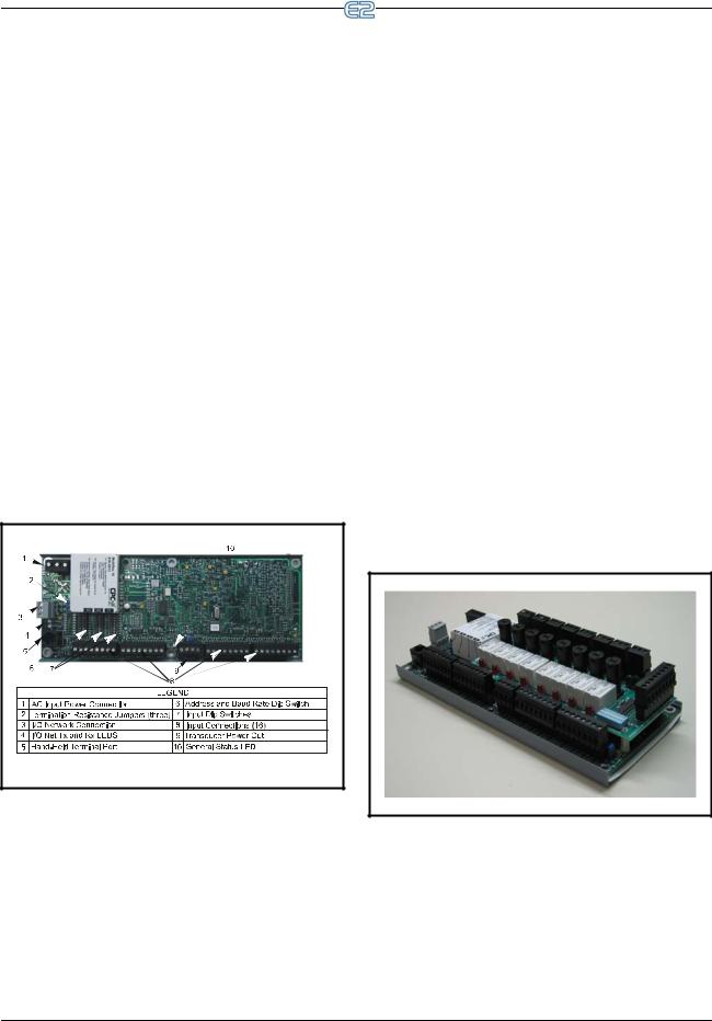
custom cell in Einstein/E2
P/N |
Gateway Model |
|
|
810-3500 |
RF Gateway |
|
|
810-3700 |
IRLDS II Gateway |
|
|
810-3760 |
RLDS Gateway |
|
|
810-3710 |
Danfoss MicroCool Gateway |
|
|
810-3711 |
Woodley Case Controller Gateway |
|
|
810-3712 |
Woodley Pack Controller Gateway |
|
|
810-3720 |
Cutler Hammer Breaker Gateway |
|
|
810-3721 |
Square D Breaker Gateway |
|
|
Table 2-5 - Gateway Board Models |
|
2.2.2MultiFlex Boards
The MultiFlex line of control system boards provides a wide variety of input, output, and smart control solutions, all of which are based on a single universal hardware platform. The board design uses flash-uploadable firmware and plug-in expansion boards to configure the base platform board and apply it for use as an input board, relay output board, analog output board, or a combination I/O board.
2.2.2.1MultiFlex 16 Input Board
Figure 2-6 - MultiFlex 16 Input Board |
The MultiFlex 16 input board offers sixteen combination analog/digital input points for use by Emerson Retail Solutions E2, Einstein, and REFLECS control systems.
The MultiFlex 16 may be used in retrofits with no additional hardware or software setup or upgrades.
The MultiFlex 16 is designed to be 100% compatible with the previous generation of Emerson Retail Solutions
input boards (the 16AI), communicates with the site controller via an RS485 connection to a REFLECS COM A&D Network or an E2 I/O Network. Dip switches on the board set the network ID (board number) and baud rate.
The board also provides both +5VDC and +12VDC output voltage points for use in powering transducers or other input devices that require power.
The MultiFlex 16 has a Hand-held Terminal interface
Section 2.2.4, Hand-held Terminal (P/N 814-3110) that may be used by technicians to view the input voltage and engineering unit values for each input point without need of a voltmeter or front panel controller display.
Table 2-6 shows the part number of the MultiFlex 16.
P/N |
Model Name |
Description |
|
|
|
810-3013 |
MultiFlex 16 |
16 analog/digital in- |
|
|
puts, no outputs |
Table 2-6 - MultiFlex 16 Input Board Model
The MultiFlex 16 is designed with several features that make it easy to install, wire, and configure. These main user interface features are shown in Figure 2-6.
2.2.2.2 MultiFlex Combination Input/ Output Boards
Figure 2-7 - MultiFlex Combination Input/Output Board (Side
View)
2-4 • E2 RX/BX/CX I&O Manual |
026-1614 Rev 4 5-JAN-2013 |
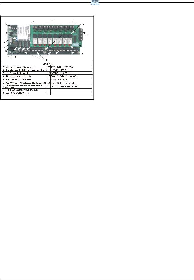
Figure 2-8 - MultiFlex Combination Input/Output Board (Top View)
There are several models of the MultiFlex board that combine the functionalities of input boards, relay output boards, digital output boards, and analog output boards.
The MultiFlex combination input/output boards are designed to be replacements for the 8IO Combination Input/Output Board, but the MultiFlex board provides several new hardware options and software features.
The MultiFlex combination I/O boards consist of up to 16 combination digital/analog inputs, and a combination of relay outputs, digital outputs, and analog outputs.
All boards feature both +5VDC and +12VDC output voltage points for use in powering transducers or other input devices that require power.
On the RS485 Network, the MultiFlex combination input/output boards present themselves to Einstein, E2, or REFLECS site controllers as 16AI Analog Input Boards, 8RO Relay Output Boards, 8DO Digital Output Boards, and/or 4AO Analog Output Boards, depending on what type of inputs or outputs are equipped. Dip switches are used to assign network ID numbers to each board type.
The MultiFlex combination input/output boards also support a Hand-held Terminal interface, Section 2.2.4,
Hand-held Terminal (P/N 814-3110) which allows technicians to view input values, check relay and analog output states, and override output points with fixed digital or analog values. For more information on MultiFlex I/O boards, refer to the MultiFlex I/O Board Installation and Operation Manual (P/N 026-1704).
Table 2-7 shows the available models of MultiFlex combination input/output boards with description and part numbers.
P/N |
Model |
Description |
|
Name |
|||
|
|
||
810-3063 |
MultiFlex |
8 analog/digital inputs, 8 re- |
|
|
88AO |
lay outputs, 4 analog out- |
|
|
|
puts |
|
810-3064 |
MultiFlex |
8 analog/digital inputs, 8 re- |
|
|
88 |
lay outputs |
|
|
|
|
|
810-3065 |
MultiFlex |
16 analog/digital inputs, 8 |
|
|
168AO |
relay outputs, 4 analog out- |
|
|
|
puts |
|
810-3066 |
MultiFlex |
16 analog/digital inputs, 8 |
|
|
168 |
relay outputs. |
|
810-3067 |
MultiFlex |
16 analog/digital inputs, 8 |
|
|
168DO |
relay outputs, 4 digital out- |
|
|
|
puts |
|
810-3072 |
MultiFlex |
16 analog/digital inputs, 16 |
|
|
1616L |
low-voltage (24VAC rated) |
|
|
|
relay outputs |
|
810-3073 |
MultiFlex |
16 analog/digital inputs, 16 |
|
|
1616LAO |
low-voltage (24VAC rated) |
|
|
|
relay outputs, and 4 analog |
|
|
|
outputs. |
|
810-3077 |
MultiFlex |
16 analog/digital inputs, 16 |
|
|
1616LDO |
low-voltage (24VAC rated) |
|
|
|
relay outputs, and 4 pulse- |
|
|
|
width modulating digital |
|
|
|
outputs |
Table 2-7 - MultiFlex Combination Input/Output Board Models
I/O Network Boards and Peripherals |
Hardware Overview • 2-5 |
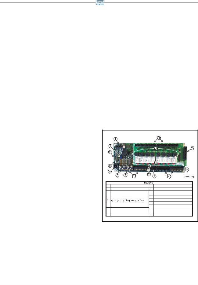
2.2.2.3MultiFlex CUB
The MultiFlex Condensing Unit Board (CUB) is a “smart” input/output board designed to control single condensing units. A single condensing unit is a self-contained compressor and condenser bearing unit which controls refrigeration in a single case line-up or walk-in cooler.
The MultiFlex CUB uses the same general hardware configuration as a MultiFlex 168AO. It is equipped with a processor and extra memory to allow it to control compressors, condensers, refrigeration, and defrost for a single condensing unit using on-board I/O and control algorithms.
The MultiFlex CUB has its own installation and operation manual, (P/N 026-1705).
2.2.2.4MultiFlex RTU (BX and CX Only)
Similar in design to the MultiFlex combination input/ output boards, the MultiFlex RTU board is designed specifically for operating package rooftop HVAC units as part of an E2 BX or REFLECS BCU building control system. The MultiFlex RTU is designed to be a replacement for the previous generation ARTC, and is 100% compatible with all legacy E2 BX and BCU systems.
The MultiFlex RTU board has 16 analog inputs, 8 relay outputs and 4 analog outputs. Most of these I/O points are reserved for sensors and input devices required to read environmental data (such as space and supply air temperature) and control all output devices that control the environment (such as heat/cool stages and dampers). Both auxiliary inputs can be configured for a variety of sensor types including any type of linear sensor. For linear sensors, the auxiliary inputs can be configured as Satellites. By doing this, the minimum and maximum voltage and minimum and maximum Engineering Unit parameters are user configurable for these inputs. The RTU relay outputs are rated for line voltage (240VAC).
The RTU board controls the rooftop unit directly with its built-in heating, cooling, and humidity control algorithms. It may operate in stand-alone mode, or it may interface with an E2 BX or BCU to control the store environment in zones and pass along logging and alarm information.
The MultiFlex RTU has its own installation and operation manual, (P/N 026-1706).
2.2.2.5 MultiFlex Rooftop Control Board (RCB) (BX and CX Only)
The MultiFlex Rooftop Control Board (RCB) (P/N 810-3062) is a rooftop HVAC control board for use
either as a stand-alone controller or in zone control applications using a Emerson Retail Solutions E2 BX building
control system. The MultiFlex RCB is capable of controlling heat and cool stages, fans, humidification and dehumidification devices, economizers using on-board I/O and control algorithms, as well as monitor and interact with other building control systems and peripherals (such as smoke alarms and CO2 sensors).
The RCB is an improved version of the MultiFlex RTU. The RCB has sixteen fully configurable analog and digital input points, whereas the RTU has only eight inputs, two of which are configurable. The RCB has four analog outputs for use in controlling variable speed fans, economizers or modulating heating and/or cooling valves, whereas the RTU has only two analog outputs for use only with VS fans and economizers. The RCB also features a more sophisticated HHT interface and updated algorithms for controlling heating, cooling, dehumidification, and air quality.
The MultiFlex RCB-P (pulse control board P/N 8103076) uses an alternate control strategy that incorporates logic for controlling heating and cooling functions.
The MultiFlex RCB has its own installation and operation manual, (P/N 026-1707).
1 |
Input Power (24VAC) |
10 |
Hand-Held Terminal Jack |
2 |
RS485 I/O Network |
11 |
Relay Output Connector |
3 |
RCB Inputs 1-8 |
12 |
Relay Output Fuses |
4 |
RCB Inputs 9-16 |
|
(2A Rated, 250V Slow-blow |
5 |
Network ID Dip Switches (S3, S4) |
13 |
Relay Status LEDs |
|
|
14 |
Output Fail-Safe Switches |
7 |
Board Status LEDs |
15 |
Analog Outputs |
|
(Code A, Code B, General Status) |
16 |
Network Status LEDs |
8 |
DC Power Outputs |
|
|
|
(3 at +5VDC, 1 at +12VDC) |
|
|
9 |
RS485 Termination Jumpers |
|
|
Figure 2-9 - MultiFlex RCB |
|
|
|
2.2.2.6MultiFlex PAK Board
The PAK is a distributed pack (rack) controller that controls compressors and condenser fans. The PAK can control up to 8 compressor groups containing up to 16 compressors. The compressor control strategy is Fixed Steps with setpoint/deadband using ON and OFF delays. Up to 20 Fixed Steps can be configured.
2-6 • E2 RX/BX/CX I&O Manual |
026-1614 Rev 4 5-JAN-2013 |
Loading...