

Page 1

RGB ELEKTRONIKA AGACIAK CIACIEK
SPÓŁKA JAWNA
Jana Dlugosza 2-6 Street
51-162 Wrocław
Poland
biuro@rgbelektronika.pl
+48 71 325 15 05
www.rgbautomatyka.pl
www.rgbelektronika.pl
DATASHEET
www.rgbautomatyka.pl
www.rgbelektronika.pl
OTHER SYMBOLS:
LX-400
LX400, LX 400, LX-400
EMERSON
Page 2
YOUR
PARTNER IN
MAINTENANCE
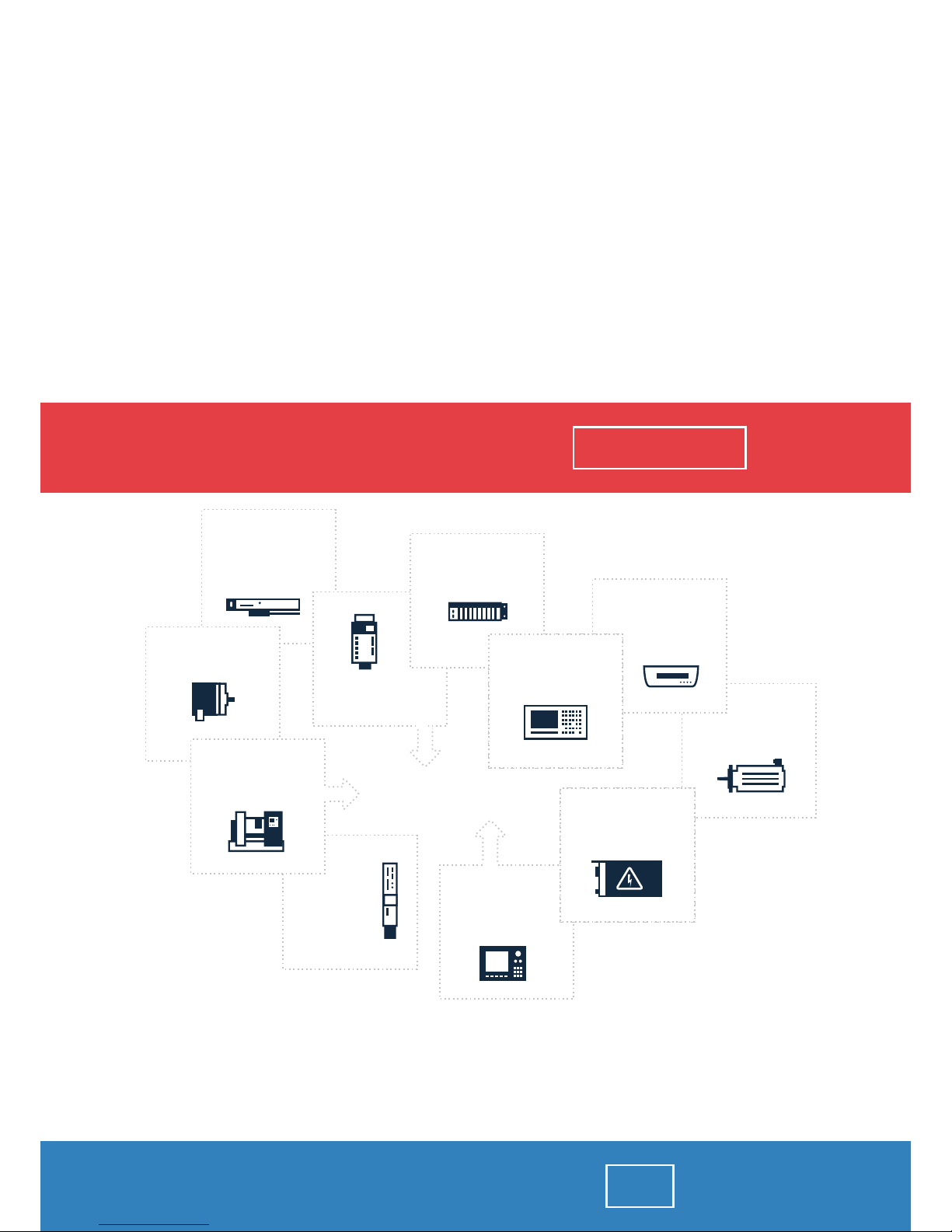
At our premises in Wrocław, we have a fully equipped servicing facility. Here we perform all the repair
works and test each later sold unit. Our trained employees, equipped with a wide variety of tools and
having several testing stands at their disposal, are a guarantee of the highest quality service.
OUR SERVICES
ENCODERS
SERVO
DRIVERS
LINEAR
ENCODERS
SERVO AMPLIFIERS
CNC
MACHINES
MOTORS
POWER
SUPPLIERS
OPERATOR
PANELS
CNC
CONTROLS
INDUSTRIAL
COMPUTERS
PLC
SYSTEMS
Repair this product with RGB ELEKTRONIKA
ORDER A DIAGNOSIS
∠
Buy this product at RGB AUTOMATYKA
BUY
∠
Page 3
User’s Guide
for the
LX
Brushless Servo Drives
Amplifier Models
LX-400, LX-700, LX-1100
Motor Models
DX-208, DX-316, DX-340
DX-455, DX-490, DX-4120
Artisan Scientific - Quality Instrumentation ... Guaranteed | (888) 88-SOURCE | www.artisan-scientific.com
Page 4

Artisan Scientific - Quality Instrumentation ... Guaranteed | (888) 88-SOURCE | www.artisan-scientific.com
Page 5
User’s Guide
for the
LX Series
Brushless Analog Servo Drives
LX400, LX-700, LX-1100
Information furnished by EMERSON EMC is believed to be
accurate and reliable. However, no responsibility is assumed by
EMERSON EMC for its use. EMERSON EMC reserves the right
to change the design or operation of the equipment described
herein and any associated motion products without notice.
EMERSON EMC also assumes no responsibility for any errors
that may appear in this document. Information in document is
subject to change without notice.
Part Number 400272-00 Rev: A.2
Date: 01/13/95j
Artisan Scientific - Quality Instrumentation ... Guaranteed | (888) 88-SOURCE | www.artisan-scientific.com
Section 1 – Page 1
Page 6
1 INTRODUCTION 1
2 INSTALLATION - MECHANICAL 2
3 INSTALLATION – ELECTRICAL 3
4 CONFIGURATION 4
5 START UP / CALIBRATIONS 5
6 SPECIAL APPLICATIONS 6
7 DIAGNOSTICS 7
8 APPENDICES 8
Artisan Scientific - Quality Instrumentation ... Guaranteed | (888) 88-SOURCE | www.artisan-scientific.com
Section 1 – Page 2
Page 7
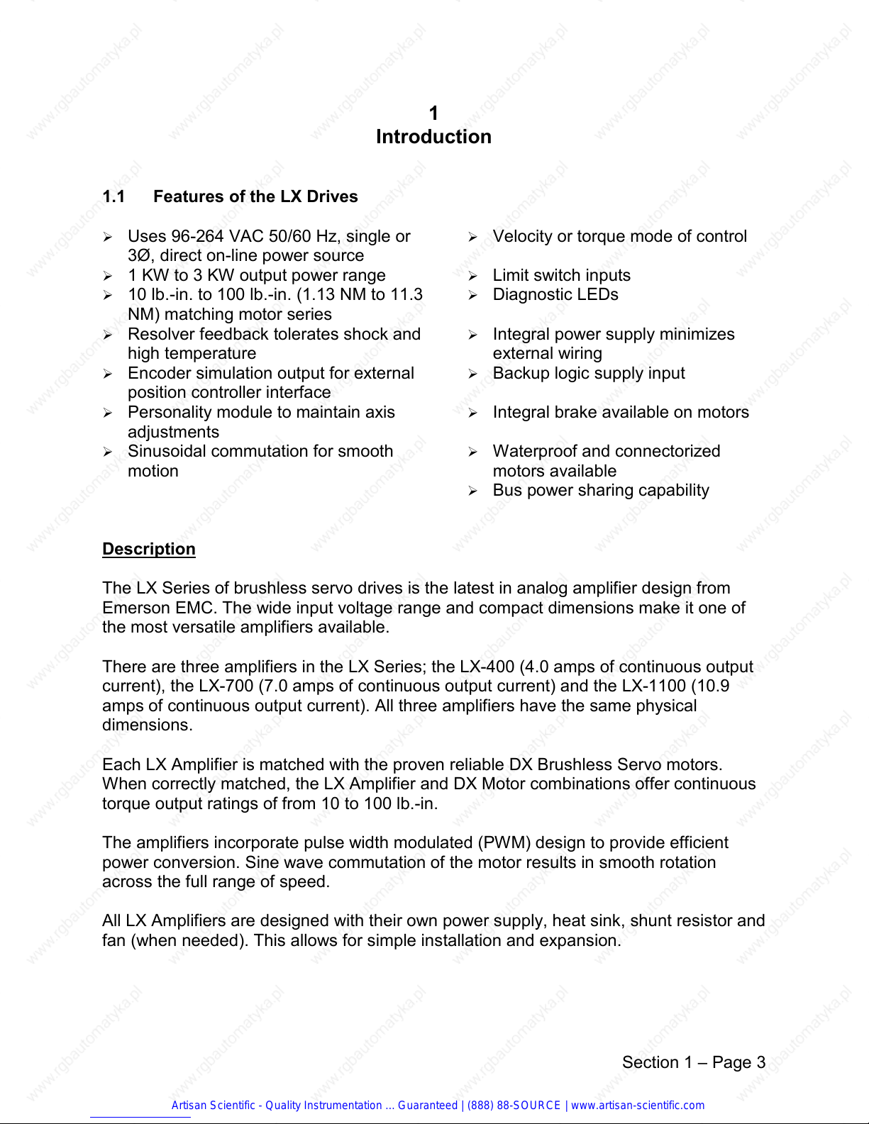
1.1 Features of the LX Drives
1
Introduction
Ø Uses 96-264 VAC 50/60 Hz, single or
Ø Velocity or torque mode of control
3Ø, direct on-line power source
Ø 1 KW to 3 KW output power range Ø Limit switch inputs
Ø 10 lb.-in. to 100 lb.-in. (1.13 NM to 11.3
Ø Diagnostic LEDs
NM) matching motor series
Ø Resolver feedback tolerates shock and
high temperature
Ø Encoder simulation output for external
Ø Integral power supply minimizes
external wiring
Ø Backup logic supply input
position controller interface
Ø Personality module to maintain axis
Ø Integral brake available on motors
adjustments
Ø Sinusoidal commutation for smooth
motion
Ø Waterproof and connectorized
motors available
Ø Bus power sharing capability
Description
The LX Series of brushless servo drives is the latest in analog amplifier design from
Emerson EMC. The wide input voltage range and compact dimensions make it one of
the most versatile amplifiers available.
There are three amplifiers in the LX Series; the LX-400 (4.0 amps of continuous output
current), the LX-700 (7.0 amps of continuous output current) and the LX-1100 (10.9
amps of continuous output current). All three amplifiers have the same physical
dimensions.
Each LX Amplifier is matched with the proven reliable DX Brushless Servo motors.
When correctly matched, the LX Amplifier and DX Motor combinations offer continuous
torque output ratings of from 10 to 100 lb.-in.
The amplifiers incorporate pulse width modulated (PWM) design to provide efficient
power conversion. Sine wave commutation of the motor results in smooth rotation
across the full range of speed.
All LX Amplifiers are designed with their own power supply, heat sink, shunt resistor and
fan (when needed). This allows for simple installation and expansion.
Section 1 – Page 3
Artisan Scientific - Quality Instrumentation ... Guaranteed | (888) 88-SOURCE | www.artisan-scientific.com
Page 8
LX Amplifiers can be easily adjusted to operate with a variety of motors and controllers.
A personality module attached to the amplifier retains all adjustments. If an amplifier
needs to be replaced, the personality module can be removed and attached to a new
amplifier, thus alleviating the re-adjustment process.
Troubleshooting is aided through the use of status LEDs located on the front panel of
the amplifiers. The LEDs continually keep the operator informed of the status of the
amplifier at all times. In addition to the LED indications, fault conditions such as resolver
fault and motor over temperature are announced as a contact signal output which can
be monitored by a host controller.
Input power voltage can range from 96 to 264 VAC 50/60 Hz without jumper or switch
selection. A 230 VAC 50/60 Hz, 3Ø supply will deliver the maximum output power.
Optimum performance from a servo system is accomplished by carefully matching the
motor and amplifier. Emerson EMC’s DX Series of servo motors has been engineered
to compliment the LX servo amplifier, providing unparalleled reliability and performance.
The DX Motors are available in a number of configurations including connectorized or
waterproof (IP65) versions. Most motors are also available with a mechanical holding
brake.
NEMA motor face dimensions are available in addition to the metric dimensions on four
motor models to greatly simplify mounting to many standard reducers.
DXE-208 NEMA 23 compatible
DXE-316 NEMA 34 compatible
DXE-455 NEMA 56C
DXE-490 NEMA 143TC
DXE-4120 NEMA 143TC
The signal and power connections are conveniently located on the drive front panel to
simplify wiring in multi-axis applications.
Artisan Scientific - Quality Instrumentation ... Guaranteed | (888) 88-SOURCE | www.artisan-scientific.com
Section 1 – Page 4
Page 9
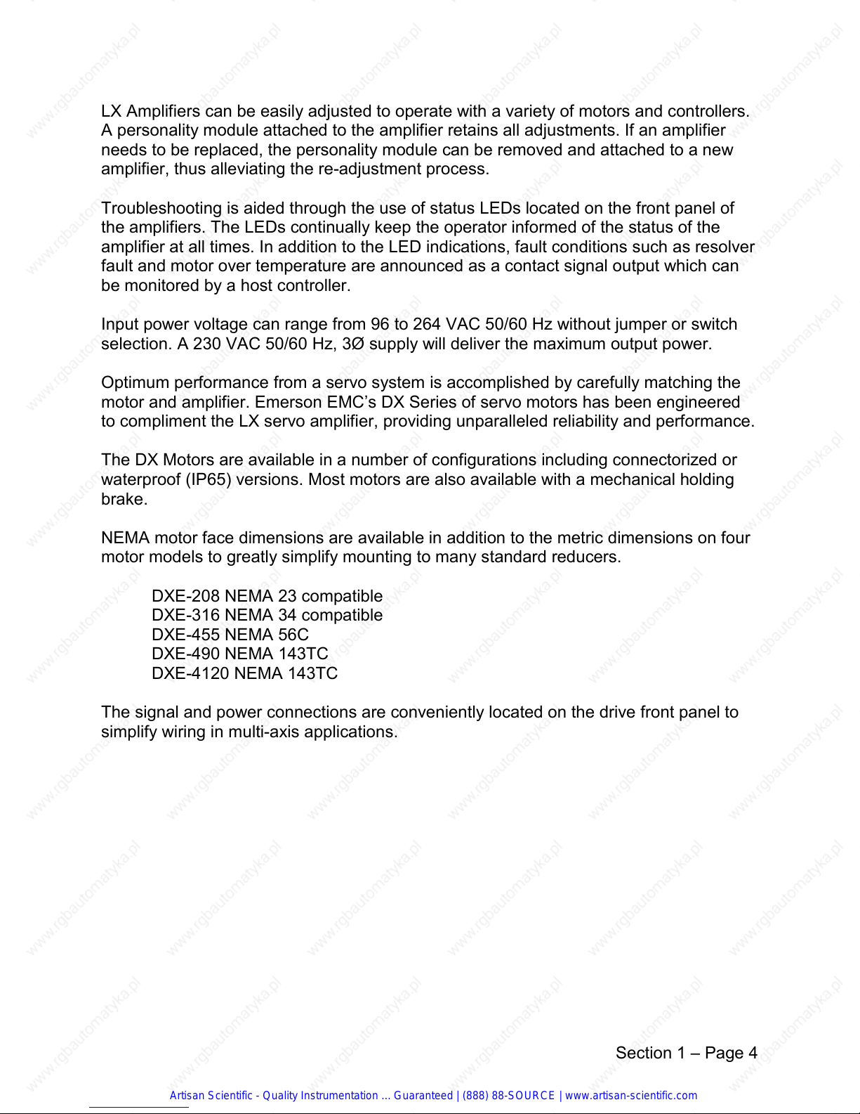
Figure 1.1 LX Drive, overall layout
Section 1 – Page 5
Artisan Scientific - Quality Instrumentation ... Guaranteed | (888) 88-SOURCE | www.artisan-scientific.com
Page 10
1.2 System Components
A complete LX package is made up of an LX amplifier, a DX motor and the appropriate
motor and resolver cables connected as shown in Figure 1.2. Cables are available from
Emerson for both the connectorized and non-connectorized motors. EMC designed
cables are recommended because they have been specially designed for the LX
amplifiers and will minimize installation problems. Table 1-A shows the available cables
and their application. For more information see Chapter 2.
Table 1-A – Motor Cabling
Motor Type Motor Model Motor Cable Resolver Cable
Waterproof Motors DXM/E-3xxW, 4xxW HPS-XXX (shielded)
250224-09
250036-00(non-
shielded)
Connectorized
DXM/E-3xxC, -455C ECM-XXX LCF-XXX
Motors
DXM/E-490C, -4120 ECL-XXX LCF-XXX
DXM/E-208 LCS-XXX
All cabling is PVC, rated for 105° C.
(XXX) is length in feet, consult an Emerson EMC application engineer for cabling
requirements over 100 ft.
Figure 1.2 Typical LX component configuration
Artisan Scientific - Quality Instrumentation ... Guaranteed | (888) 88-SOURCE | www.artisan-scientific.com
Section 1 – Page 6
Page 11
1.2.1 User Adjustments and Options
The amplifiers each have a personality module that is used to set up the drive for the
application as required. The drive features which are customized by the user on the
personality board include:
Continuous Current limit value
Maximum Speed Range (3000 / 6000 rpm)
Motor pole selection
Calibration adjustments
Limit Switch enable and polarity
Encoder output resolution
The Limit switch inputs and Emulates encoder outputs are standard on the LX, however
these features can be deleted when purchasing quantities of drives to further reduce
costs. See your Emerson Sales Representative for further details.
1.3 Basic Function and Operation
The amplifier is designed to operate in either a velocity command or current (torque)
mode with an analog ±10 volt command. The velocity command input is a true
differential input while the current command input is a single ended input that doubles
as the current demand output. This signal can be used as a master output in torque
helper applications as well as a test point for detecting the actual motor current required
in an application. For details about the current command mode see the “Special
Applications” section 6.
1.3.1 Feedback Signals
Speed and position feedback signals are accurately derived from the position
information coming from the resolver mounted on the motor shaft.
The derived tachometer signal is used by the amplifiers speed control circuitry and is
available as an analog signal output on the connection strip. This tachometer output
provides analog voltage proportional to the shaft speed with a range of ± 10V equal to ±
3000 / 6000 rpm.
Emulated encoder outputs with zero markers are provided on the standard LX amplifier
for use with position controllers.
1.3.2 Control Loops
The LX drive uses two high performance control loops (current and velocity) to control
the speed and torque of the motor. The “current loop” controls the current flowing into
the motor by comparing the current flowing in the motor to the current command from
the reference signal and correcting it to maintain the commanded current. The current
command can come from either an external controller or directly from the LX amplifiers
speed loop. The velocity loop controls the motor velocity by comparing the actual
Artisan Scientific - Quality Instrumentation ... Guaranteed | (888) 88-SOURCE | www.artisan-scientific.com
Section 1 – Page 7
Page 12
velocity of the motor to the velocity commanded by the drive and adjusting the current
command as needed to maintain the commanded velocity.
Velocity Loop
In the velocity loop circuit the error signal is processed by a P.I.D. (Proportional, Integral
and Derivative). The output of the P.I.D. filter is the current reference signal also
available for test on terminal 2 of the front connector. The voltage on this point is ± 10
VDC. At ± 10V the drive generates the maximum current in the designated direction.
All the adjustments shown on the block diagram in Figure 1-3. Zero offset, proportional
gain, response, accel/decel ramp gradient and full scale speed are located on the
personality board and the potentiometers are accessible from the front panel.
Current Loop and Limiting
The current error signal is generated comparing the output of the current limiting stage
with the actual current in the motor. The current error signal is computed to generate
the PWM signals driving the IGBT final stage. In the block diagram in Figure 1-3, the
IGBT devices are shown as switches.
Current Limiting
In the current loop circuit there is a current limiting circuit referred to as Ixt, which
continuously monitors the current commanded and delivered into the motor.
The Ixt limiting circuit is not operational in the current command
mode. See Chapter 6 for details on implementing current command
mode.
This limiting circuit estimates the heating of the motor by continuously monitoring the
amount of current in the motor and the length of time this current has been flowing. The
limiting value is determined by the setting of dip switches on the personality board. If the
current requested exceeds the value set by the dip switches, the Ixt control circuit will
determine how long the commanded peak current will be allowed before limiting the
delivered current to the dip switch value. This current limiting is not a fault condition but
rather an Ixt current fold back limiting and is so indicated by the High Irms LED and
High Irms output. When the drive is in the Ixt limit status, the RED led (HIGH Irms) lights
and terminal 12 becomes open circuit. Once current fold back is engaged the drive will
continue in the limited current condition until the current commanded is reduced below
the dip switch level for length of time sufficient to reset the Ixt limiting circuitry. The
amount of time allowed above the continuous level before Ixt limiting varies is
dependent on the percent of RMS current the drive has been running. Peak current
availability is also dependent on the level of current demand below and the amount of
time below the dip switch level. In addition to the current foldback limiting, the LX
amplifiers also have short circuit protection. This prevents destruction of the amplifiers
due to short circuits either from a short that is applied while in operation or from a short
circuit in effect at power ON.
Artisan Scientific - Quality Instrumentation ... Guaranteed | (888) 88-SOURCE | www.artisan-scientific.com
Section 1 – Page 8
Page 13
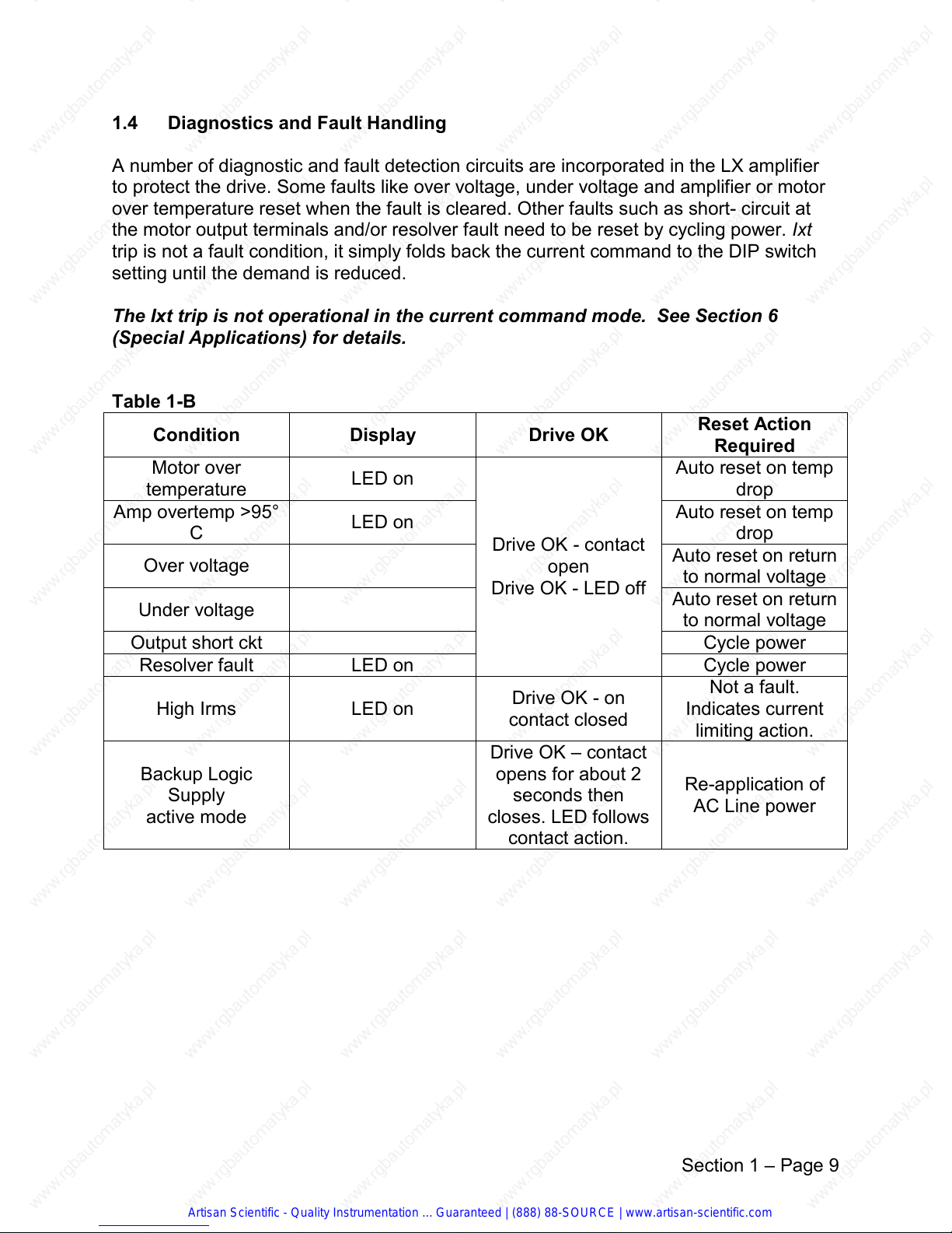
1.4 Diagnostics and Fault Handling
A number of diagnostic and fault detection circuits are incorporated in the LX amplifier
to protect the drive. Some faults like over voltage, under voltage and amplifier or motor
over temperature reset when the fault is cleared. Other faults such as short- circuit at
the motor output terminals and/or resolver fault need to be reset by cycling power. Ixt
trip is not a fault condition, it simply folds back the current command to the DIP switch
setting until the demand is reduced.
The Ixt trip is not operational in the current command mode. See Section 6
(Special Applications) for details.
Table 1-B
Condition Display Drive OK
Motor over
temperature
Amp overtemp >95°
C
LED on
LED on
Drive OK - contact
Over voltage
Drive OK - LED off
Under voltage
open
Reset Action
Required
Auto reset on temp
drop
Auto reset on temp
drop
Auto reset on return
to normal voltage
Auto reset on return
to normal voltage
Output short ckt Cycle power
Resolver fault LED on
High Irms LED on
Drive OK - on
contact closed
Cycle power
Not a fault.
Indicates current
limiting action.
Drive OK – contact
Backup Logic
Supply
active mode
opens for about 2
seconds then
closes. LED follows
Re-application of
AC Line power
contact action.
Artisan Scientific - Quality Instrumentation ... Guaranteed | (888) 88-SOURCE | www.artisan-scientific.com
Section 1 – Page 9
Page 14

1.5 Power Section
On the main board, the high current and the signal sections are optically isolated.
Looking at the block diagram (Figure 1-3) the main functions of the drive can be
identified. The power stage DC bus is supplied by the AC line input to the drive and the
internal diode bridge rectifier followed by a set of filtering capacitors. The internal SMPS
(Switching Mode Power Supply) operates off the power DC bus to generate all the
voltages necessary to supply the low power and control electronics.
To dissipate the energy generated by the motor during high gradient deceleration rates
and continuous regeneration against a load, the braking circuit shunts the excess
current generated by the motor through the internal shunt (braking) resistor. The yellow
LED lights when the shunt circuit is active. If the power capacity of the internal braking
resistor is insufficient for heavy cycles, an external braking resistor with greater power
should be added and the internal resistor disconnected. See the “Special Applications”
in Chapter 6 for more information.
Artisan Scientific - Quality Instrumentation ... Guaranteed | (888) 88-SOURCE | www.artisan-scientific.com
Section 1 – Page 10
Page 15
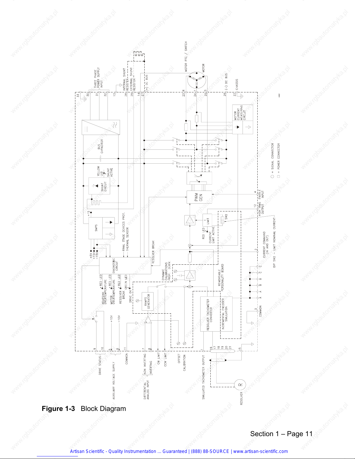
Figure 1-3 Block Diagram
Section 1 – Page 11
Artisan Scientific - Quality Instrumentation ... Guaranteed | (888) 88-SOURCE | www.artisan-scientific.com
Page 16
2
INSTALLATION -- MECHANICAL
2.1 Installation
The following installation requirements, methods and procedures are provided to assure
reliable and trouble free installation of your Emerson MC LX Drive.
The methods and procedures are outlined on the following pages and include site
requirements, safety considerations, power and fusing requirements, wire and
transformer sizing, noise suppression, and I/O wiring.
2.2 Safety Considerations
The installer/user is responsible for incorporating appropriate safety features into the
equipment to prevent injury to personnel or damage to equipment.
The installer/user has the responsibility to comply with the safety requirements of the
system. This includes installing the system with an appropriate master interlock switch
for emergency shut down and using the proper wire and transformer sizes (if necessary)
to fit the system. This section will provide you with the information to complete a trouble
free installation.
WARNING!
The user is responsible for providing emergency interlock switches that will
remove AC power from the system any time the equipment is not running, or
when the emergency stop is activated. This is to eliminate the possibility of
electrocution or unwanted movement of the motor. The safety ground
connections should only be disconnected for servicing and only after all AC
power has been removed.
2.3 Selecting an Enclosure
The LX drive is designed for the industrial environment. However, no sophisticated
electronic system can tolerate certain atmospheric contaminants such as moisture, oils,
conductive dust, chemical contaminates and metallic particles. Therefore, if the drive is
going to be subjected to this type of environment it must be mounted vertically in a
NEMA type 12 enclosure.
Proper ventilation and filtering must also be provided. If the equipment environment is
above 50° C, cooling is mandatory. The amount of cooling depends on the size of the
enclosure, the thermal transfer of the enclosure to the ambient air and the amount of
power being dissipated inside the enclosure. Your enclosure supplier can assist you in
properly selecting an enclosure for your application.
Artisan Scientific - Quality Instrumentation ... Guaranteed | (888) 88-SOURCE | www.artisan-scientific.com
Section 2 – Page 1
Page 17
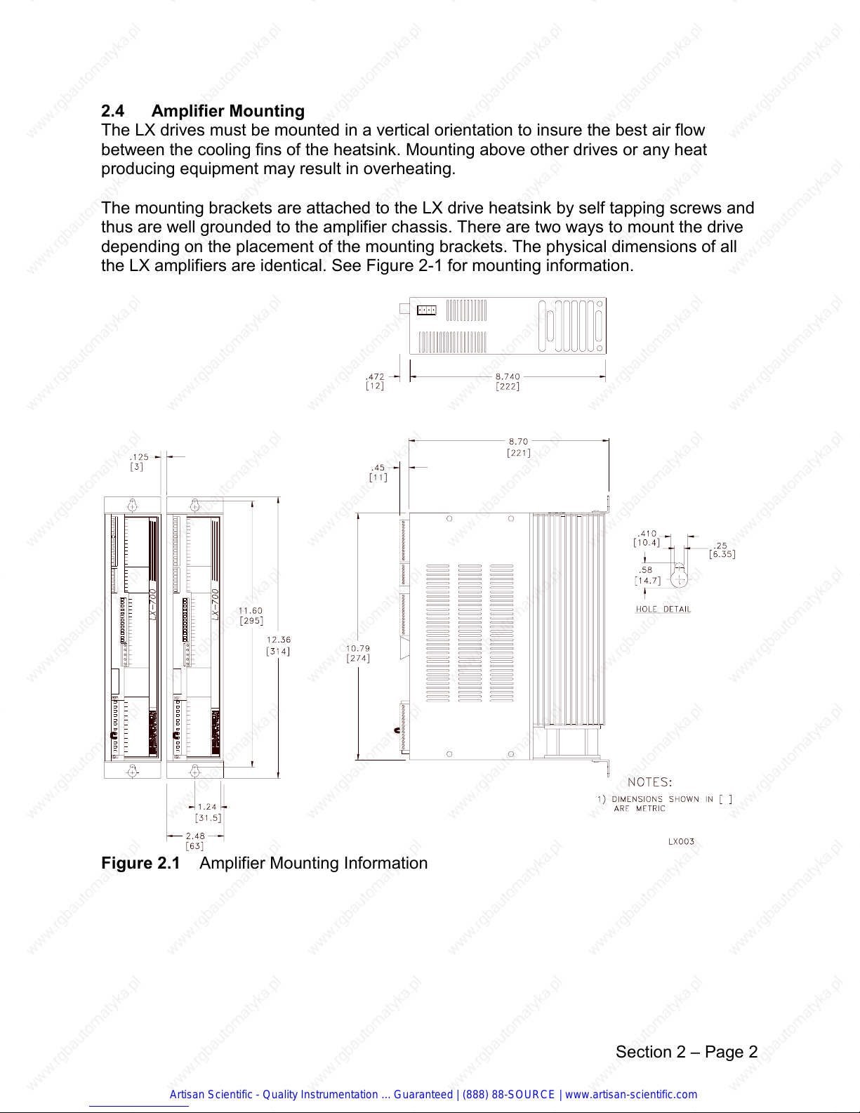
2.4 Amplifier Mounting
The LX drives must be mounted in a vertical orientation to insure the best air flow
between the cooling fins of the heatsink. Mounting above other drives or any heat
producing equipment may result in overheating.
The mounting brackets are attached to the LX drive heatsink by self tapping screws and
thus are well grounded to the amplifier chassis. There are two ways to mount the drive
depending on the placement of the mounting brackets. The physical dimensions of all
the LX amplifiers are identical. See Figure 2-1 for mounting information.
Figure 2.1 Amplifier Mounting Information
Artisan Scientific - Quality Instrumentation ... Guaranteed | (888) 88-SOURCE | www.artisan-scientific.com
Section 2 – Page 2
Page 18
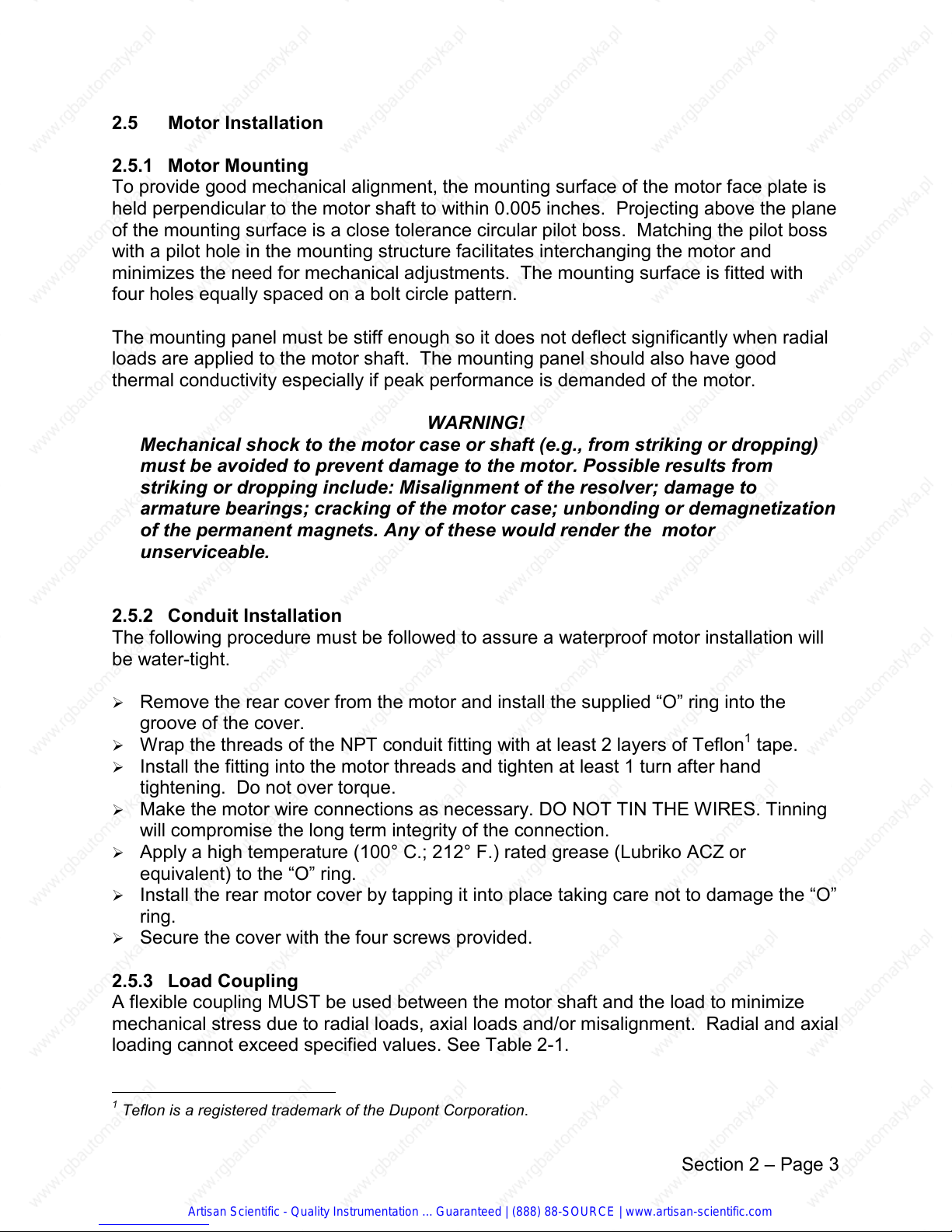
2.5 Motor Installation
2.5.1 Motor Mounting
To provide good mechanical alignment, the mounting surface of the motor face plate is
held perpendicular to the motor shaft to within 0.005 inches. Projecting above the plane
of the mounting surface is a close tolerance circular pilot boss. Matching the pilot boss
with a pilot hole in the mounting structure facilitates interchanging the motor and
minimizes the need for mechanical adjustments. The mounting surface is fitted with
four holes equally spaced on a bolt circle pattern.
The mounting panel must be stiff enough so it does not deflect significantly when radial
loads are applied to the motor shaft. The mounting panel should also have good
thermal conductivity especially if peak performance is demanded of the motor.
WARNING!
Mechanical shock to the motor case or shaft (e.g., from striking or dropping)
must be avoided to prevent damage to the motor. Possible results from
striking or dropping include: Misalignment of the resolver; damage to
armature bearings; cracking of the motor case; unbonding or demagnetization
of the permanent magnets. Any of these would render the motor
unserviceable.
2.5.2 Conduit Installation
The following procedure must be followed to assure a waterproof motor installation will
be water-tight.
Ø Remove the rear cover from the motor and install the supplied “O” ring into the
groove of the cover.
Ø Wrap the threads of the NPT conduit fitting with at least 2 layers of Teflon
Ø Install the fitting into the motor threads and tighten at least 1 turn after hand
1
tape.
tightening. Do not over torque.
Ø Make the motor wire connections as necessary. DO NOT TIN THE WIRES. Tinning
will compromise the long term integrity of the connection.
Ø Apply a high temperature (100° C.; 212° F.) rated grease (Lubriko ACZ or
equivalent) to the “O” ring.
Ø Install the rear motor cover by tapping it into place taking care not to damage the “O”
ring.
Ø Secure the cover with the four screws provided.
2.5.3 Load Coupling
A flexible coupling MUST be used between the motor shaft and the load to minimize
mechanical stress due to radial loads, axial loads and/or misalignment. Radial and axial
loading cannot exceed specified values. See Table 2-1.
1
Teflon is a registered trademark of the Dupont Corporation.
Artisan Scientific - Quality Instrumentation ... Guaranteed | (888) 88-SOURCE | www.artisan-scientific.com
Section 2 – Page 3
Page 19
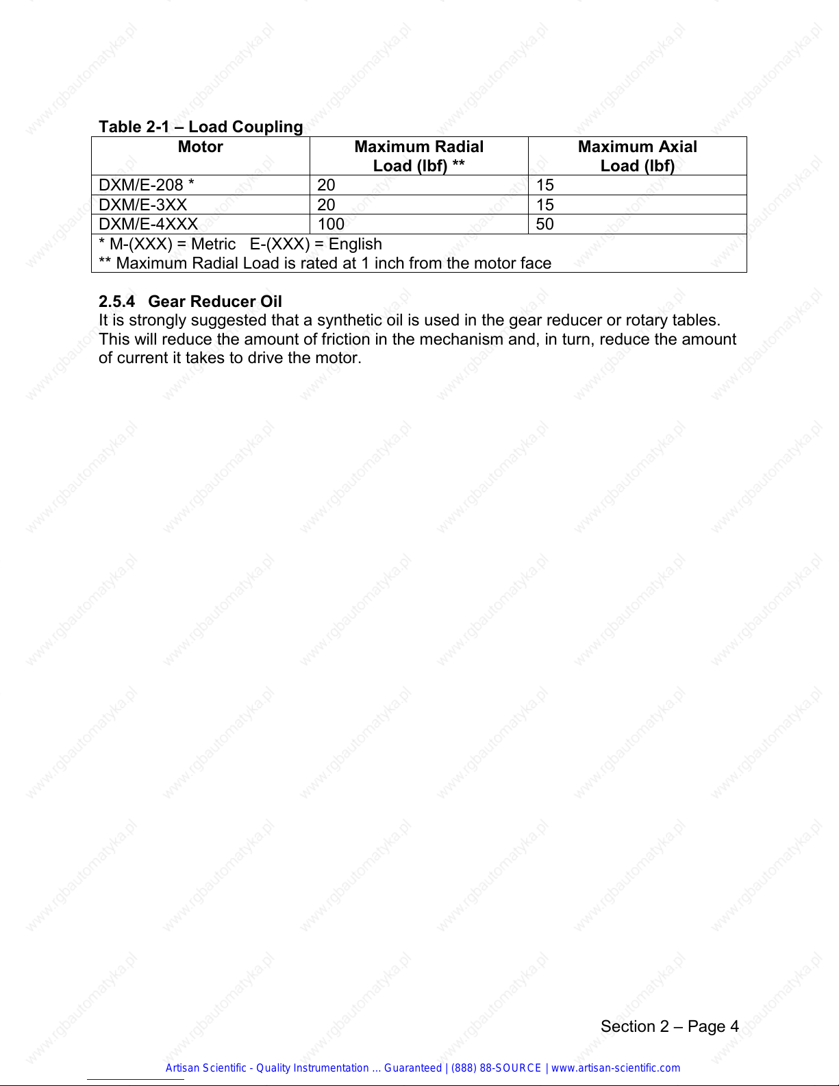
Table 2-1 – Load Coupling
Motor Maximum Radial
Load (lbf) **
Maximum Axial
Load (lbf)
DXM/E-208 * 20 15
DXM/E-3XX 20 15
DXM/E-4XXX 100 50
* M-(XXX) = Metric E-(XXX) = English
** Maximum Radial Load is rated at 1 inch from the motor face
2.5.4 Gear Reducer Oil
It is strongly suggested that a synthetic oil is used in the gear reducer or rotary tables.
This will reduce the amount of friction in the mechanism and, in turn, reduce the amount
of current it takes to drive the motor.
Artisan Scientific - Quality Instrumentation ... Guaranteed | (888) 88-SOURCE | www.artisan-scientific.com
Section 2 – Page 4
Page 20
3
INSTALLATION -- ELECTRICAL
3.1 Wiring
Wiring of any industrial equipment should be done with some consideration for future
troubleshooting and repair. It is a good idea that wiring be either color coded and/or
tagged with industrial wire tabs.
3.1.1 Interlocking
The user is responsible for emergency interlock switches. Any master interlock should
be wired to shut down AC power to all parts of the system. Your system should be
designed such that power is disconnected from the output loads any time the equipment
is not running or when the emergency stop is activated.
3.1.2 EMI/RFI Interference
If there is sensitive electronic equipment (digital computer, test equipment, etc.)
operating on the same AC power line as the Drive, additional EMI/RFI filtering may be
required to reduce the effects of conducted AC line noise.
3.1.3 Shielding Suggestions
Effects of electrical noise on the electronic equipment are greatly reduced when the
techniques outlined below are closely followed.
Ø Do not run low power control signals and high power wiring in the same raceway.
Ø If mixing wires cannot be avoided, then the low voltage control input and output
wiring must be shielded. The shield for these wires should be connected to ground
only at the source end of the signals.
Ø Do not connect both ends of a shielded cable to ground unless specified by the
manufacturer to do so. This may cause a ground loop condition which could cause
erratic equipment behavior and may be very difficult to locate.
Ø All the wires in the system must be kept as short as possible.
Artisan Scientific - Quality Instrumentation ... Guaranteed | (888) 88-SOURCE | www.artisan-scientific.com
Section 3– Page 1
Page 21
3.2 Magnetic Coil Noise
In the case of DC coils, a diode is installed across the coil in a direction that will cause
the voltage transient to be dissipated through the diode.
Figure 3.1 DC Coil Suppression
In the case of AC coils, a capacitor and resistor are installed across the coil to suppress
the unwanted transients.
Figure 3.2 AC Coil Suppression
3.3 Grounding
The GND terminal of the drive is bonded to the frame and the mounting tabs. There are
two acceptable methods for connecting the grounds of the enclosure and other
electrical equipment to the Earth ground. Figure 3.3 shows the ideal grounding method
providing a grounding point isolated from the enclosure and ground all the electrical
equipment to this one point. From there, a grounding wire with good conductivity will be
run to the enclosure cabinet ground point. The machine ground wire and earth ground
supply wire are connected to this enclosure ground point. This method provides
maximum isolation of the control and servo grounds from the machine and other
sources of ground imbalances and noise. In most cases however, a single point
enclosure ground can be used as shown in Figure 3.5.
Artisan Scientific - Quality Instrumentation ... Guaranteed | (888) 88-SOURCE | www.artisan-scientific.com
Section 3– Page 2
Page 22

Figure 3.3 Ideal grounding example, schematic
Figure 3.4 Ideal grounding example, pictorial
Artisan Scientific - Quality Instrumentation ... Guaranteed | (888) 88-SOURCE | www.artisan-scientific.com
Section 3– Page 3
Page 23
Figure 3.5 Acceptable grounding example
3.4 AC Input
The drives are designed to operate on a 50/60 Hz, three phase AC power line. The AC
voltage of this power line must be within the specified range of 96-264 VAC. If at any
time the input line voltage falls below 96 VAC the drive will drop out the Drive OK output
contact and will disable the output bridge.
3.4.1 Single Phase Power
The LX drives will deliver maximum performance when operating on three phase,
however, 96 to 264 volt, 1Ø can be used with a derating factor.
Note: Consult Emerson EMC customer service if 1Ø power supply is used.
Artisan Scientific - Quality Instrumentation ... Guaranteed | (888) 88-SOURCE | www.artisan-scientific.com
Section 3– Page 4
Page 24

Table 3-A – Power Wiring and Fusing
Model MINIMUM WIRE SIZE AWG
1
FUSE RATING AMPS
LX-400 20 5
LX-700 18 8
LX-1100 16 12
1
Recommended fuse type is a LOW PEAK delayed action type fuse such as Bus brand
type LPN fuse. A standard rated delayed action or dual element fuse such as Bus
brand FRN may be used in lieu of the Low peak type fuse when availability dictates but
the level of drive protection afforded by the LPN fuse is better. In the case of a short
circuit in the drive, there will be fewer failed drive components if a low peak fuse is used
because it will blow before the currents reach a high level.
3.4.2 Transformer Power Supply
One 3Ø transformer may be used to supply more than one drive. The secondary
winding should be set up to supply the sum of the nominal current of the motors
connected. The transformer secondary must be a delta configuration or a WYE
configuration with a full current grounded neutral connection due to the harmonics
induced when supplying power to a rectified power supply. The type of primary winding
is immaterial.
Figure 3.6 Power supply example
Artisan Scientific - Quality Instrumentation ... Guaranteed | (888) 88-SOURCE | www.artisan-scientific.com
Section 3– Page 5
Page 25
The following formula can be used for transformer sizing. For each secondary winding,
the power in VA is:
Ps - (Paz * 1.5) * 1.73 / √ (n+2)
where:
Paz = (Vm1*Cm1 + Vm2* Cm2 + ............ +
Vmn*Cmn)
Vm = motor max speed in rad/sec (RPM/9.55)
Cm = nominal motor torque in Nm(lb-in/8.85)
1.73/√(n+2) = corrective factor when using more than one
drive supplied in parallel with n= number of drives.
The overall transformer power in VA is:
Pt = Ps1 + Ps2 ............ + Psn
where:
Ps1 = power of secondary winding 1
Ps2 = power of secondary winding 2
Psn = power of secondary winding n
Artisan Scientific - Quality Instrumentation ... Guaranteed | (888) 88-SOURCE | www.artisan-scientific.com
Section 3– Page 6
Page 26
3.4.3 Transformer Fusing
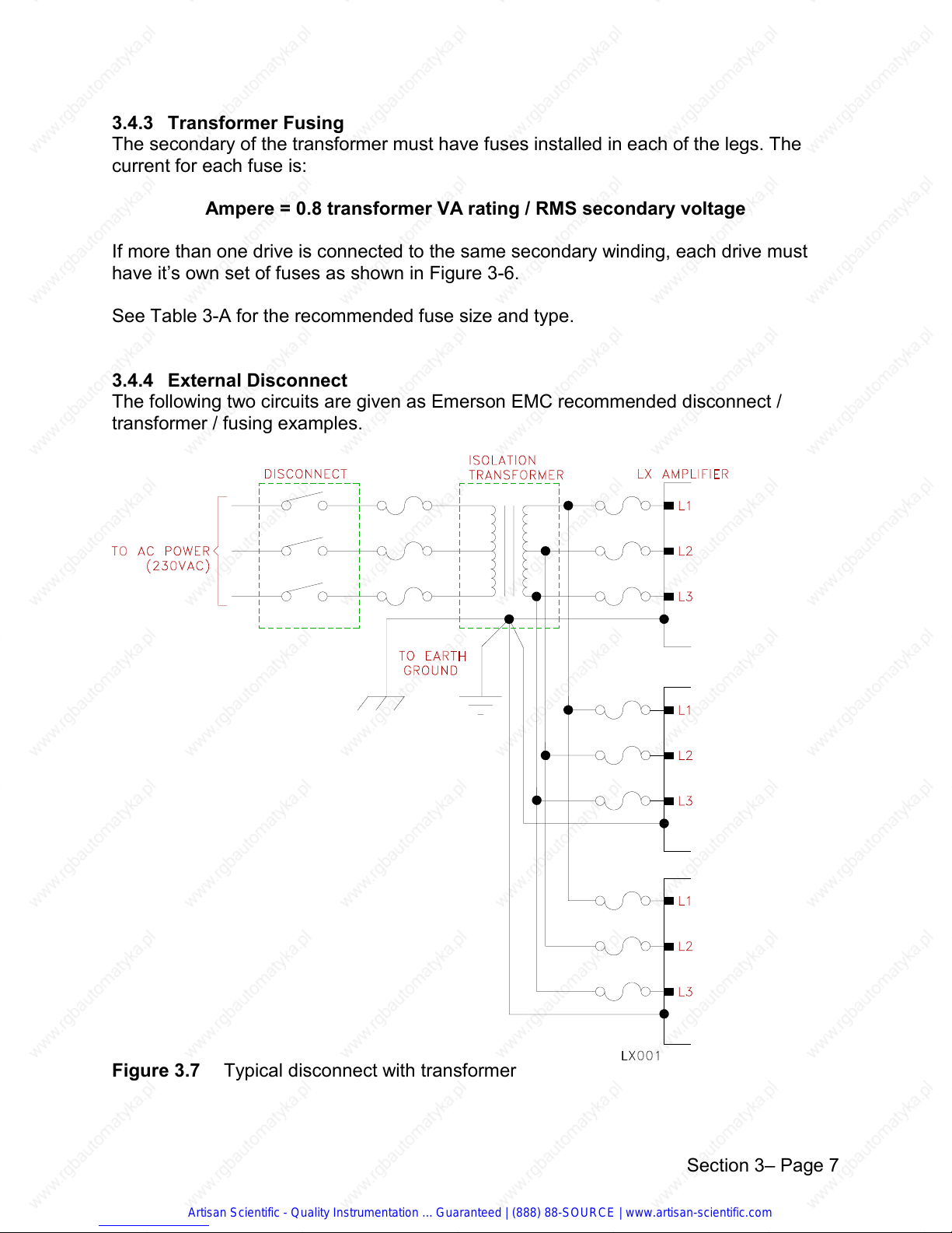
The secondary of the transformer must have fuses installed in each of the legs. The
current for each fuse is:
Ampere = 0.8 transformer VA rating / RMS secondary voltage
If more than one drive is connected to the same secondary winding, each drive must
have it’s own set of fuses as shown in Figure 3-6.
See Table 3-A for the recommended fuse size and type.
3.4.4 External Disconnect
The following two circuits are given as Emerson EMC recommended disconnect /
transformer / fusing examples.
Figure 3.7 Typical disconnect with transformer
Artisan Scientific - Quality Instrumentation ... Guaranteed | (888) 88-SOURCE | www.artisan-scientific.com
Section 3– Page 7
Page 27

Figure 3.8 Typical disconnect without transformer
Section 3– Page 8
Artisan Scientific - Quality Instrumentation ... Guaranteed | (888) 88-SOURCE | www.artisan-scientific.com
Page 28

3.5 Motor Connections
DX motors are available in two different styles for most models; waterproof designated
by a W in the motor model number, and connectorized, designated by a C in the motor
model number. The waterproof type has been designed to meet IP65 waterproofing
standards. Cable entries are made through American National Standard Tapered Pipe
Threads (NPT) conduit holes. The connectorized type of motors come equipped with
one or two MS style multi-pin connectors. See Table 3-B for motor connector options.
Table 3-B – Motor Connector Options
DX MOTOR
MODEL
DX-208 YES (ONE) N/A
DX-316 YES (TWO) YES
DX-340 YES (TWO) YES
DX-455 YES (TWO) YES
DX-490 YES (TWO) YES
DX-4120 YES (TWO) YES
WITH MS STYLE
CONNECTORS
WITH NPT
HOLES
Note: Motors equipped with MS style connectors meet IP65 waterproofing
standards. However, the mating cables and connectors do not. If waterproofing
is required, motors with NPT conduit holes should be ordered.
3.5.1 Motor Thermal Protection
In each of the motors there is at least one level of thermal protection. Every motor
model has three 150° C thermal switches mounted directly within the motor windings.
The contacts are connected in series and are available via the motor connections for
controller sensing of motor temperature. The Waterproof motors also include a second
thermal switch which is electrically in series with the three winding sensors and is
mounted in the area of the user wiring terminal strips. This second thermal switch is set
to a lower temperature (80° C) to protect the lower temperature type PVC insulated
wiring that may be used for the motor connections. This lower temperature thermal
switch may be shunted out of the circuit by a jumper on the connection board when the
higher temperature connection wiring is used. All motor wiring supplied by Emerson
EMC is rated for at least 105° C., so the low temperature switch can be jumpered out.
The contacts remain closed as long as the temperature stays within operating range.
When the temperature exceeds the specification, the contacts will open. These
contacts are generally connected to the servo amplifier which shuts the amplifier off to
protect the motor from damage. The thermal switch contact ratings are 30VDC, 500
milliamps.
Artisan Scientific - Quality Instrumentation ... Guaranteed | (888) 88-SOURCE | www.artisan-scientific.com
Section 3– Page 9
Page 29
3.5.2 Waterproof Motor Connections
The waterproof motors are provided with NPT (National Pipe Tapered Threads) for easy
connection to waterproof conduit fittings. The motor power wiring can be either a cable
assembly or discrete wires. Shielded motor power cables are highly recommended for
best system performance and for minimum EMI radiation from the high frequency
switching of the amplifier. Emerson EMC has shielded power cable available in bulk
under part number HPS-XXX (XXX is the length in feet). If a shielded motor power cable
is used, the shield should be connected to ground at both ends of the cable. If discrete
motor power wires are used, the power wires should be twisted or braided together but
not twisted with the ground wire. All wiring must be done with industrial grade insulated
stranded wire capable of withstanding the environmental conditions of the application.
See Table 3-C for recommended motor power and ground wire gauge sizes.
3.5.3 Resolver Wiring
The resolver cable must be comprised of twisted and shielded pair with an overall
braided shield. The resolver cable conductors should be 18 to 24 gauge. The use of
larger gauge wire will prematurely fatigue the terminals and make installation difficult.
Emerson EMC has resolver cabling available in bulk for ease of installation (PN
250224-09). The resolver shield should be connected only at the controller (excitation)
end of the cable.
Table 3-C – Power wire recommendations
Motor Minimum Wire Size Recommended Wire Type
DX-208 20 AWG 300V, 105° C
DX-316 20 AWG 300V, 105° C
DX-340 18 AWG 300V, 105° C
DX-455 18 AWG 300V, 105° C
DX-490 16 AWG 300V, 105° C
DX-4120 16 AWG 300V, 105° C
Artisan Scientific - Quality Instrumentation ... Guaranteed | (888) 88-SOURCE | www.artisan-scientific.com
Section 3– Page 10
Page 30

Figure 3.9 DXM-3XXW motor wiring
Section 3– Page 11
Artisan Scientific - Quality Instrumentation ... Guaranteed | (888) 88-SOURCE | www.artisan-scientific.com
Page 31

Figure 3.10 DXM-4XX(X)W motor wiring
Section 3– Page 12
Artisan Scientific - Quality Instrumentation ... Guaranteed | (888) 88-SOURCE | www.artisan-scientific.com
Page 32

3.5.4 Connectorized Motor Wiring
Connectorized motors are equipped with two military style connectors for easy
connection and disconnect. This is especially useful for equipment that is disassembled
an reassembled many times. All the motor models except for the DX- 208 motor have
two connectors. One makes the motor power and ground connections and the other
makes the resolver and thermal switch connections. The connectors are different to
eliminate the possibility of incorrect connections. The LCF-XXX feedback cable makes
the resolver / thermal switch connection. The ECM- XXX and ECS-XXX cables make
the motor power, ground and brake connections (if required). The DX-208 motor is very
small and so is supplied with one integrated connector. The LCS-XXX cable includes
all the wiring for the DX-208 motor. The DX-208 motor is not available with a brake so
no brake wiring is included in the cable. The following figures show the wiring diagrams
for the ECM-XXX, ECL-XXX, LCS-XXX and LCF-XXX cables.
Table 3-D – Motor Cabling
Motor Type Motor Model Motor Cable Resolver Cable
Waterproof Motors DXM/E-3xxW, 4xxW HPS-XXX (shielded)
250224-09
250036-00(non-
shielded)
Connectorized
Motors
DXM/E-3xxC, -455C ECM-XXX LCF-XXX
DXM/E-490C, -4120 ECL-XXX LCF-XXX
DXM/E-208 LCS-XXX
All cabling is PVC, rated for 105° C.
(XXX) is length in feet, consult an Emerson EMC application engineer for cabling
requirements over 100 ft.
Cable Notes:
1. Applications that require LCS or LCF cables longer than 100 ft. should be
discussed with Emerson EMC’s Applications department.
2. As a general rule, the minimum cable bend radius is ten times the cable outer
diameter.
3. Motors with MS style connectors should be mounted with the connectors pointing
downward. This provides added protection against dust and water damage.
Artisan Scientific - Quality Instrumentation ... Guaranteed | (888) 88-SOURCE | www.artisan-scientific.com
Section 3– Page 13
Page 33

Figure 3.11 LCF-XXX Cable Wiring Diagram
Figure 3.12 ECM/ECL-XXX Cable Wiring Diagram
Figure 3.13 LCS-XXX Cable Wiring Diagram
Artisan Scientific - Quality Instrumentation ... Guaranteed | (888) 88-SOURCE | www.artisan-scientific.com
Section 3– Page 14
Page 34

3.6 Brake Motors
Brake motors are intended for applications where there is a load on the motor that must
be immovable with the power off. This is usually the case with vertical loads whether or
not they are counterbalanced. The motor brake will apply braking force with no power
applied to the brake connections and will disengage when the correct voltage is applied
to the motor brake terminals. See Figures 3-14, 3-15, 3-16 for connections to brake
motors of either waterproof or connectorized type.
Figure 3.14 Connectorized Motor Brake Connection
Section 3– Page 15
Artisan Scientific - Quality Instrumentation ... Guaranteed | (888) 88-SOURCE | www.artisan-scientific.com
Page 35

Figure 3.15 DXM-3XXW Motor Brake Connection
Figure 3.16 DXM-4XX(X)W Motor Brake Connection
Artisan Scientific - Quality Instrumentation ... Guaranteed | (888) 88-SOURCE | www.artisan-scientific.com
Section 3– Page 16
Page 36
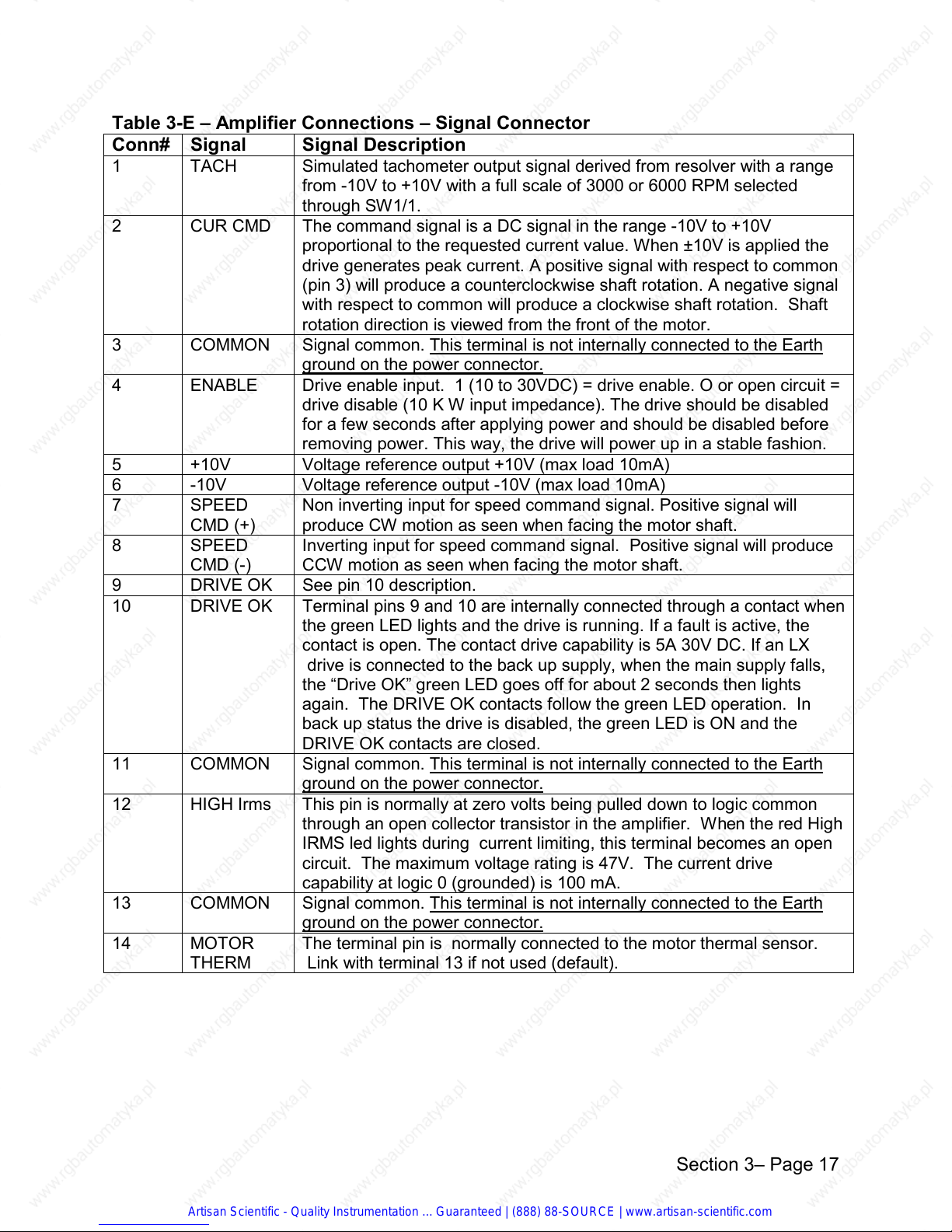
Table 3-E – Amplifier Connections – Signal Connector
Conn# Signal Signal Description
1 TACH Simulated tachometer output signal derived from resolver with a range
from -10V to +10V with a full scale of 3000 or 6000 RPM selected
through SW1/1.
2 CUR CMD The command signal is a DC signal in the range -10V to +10V
proportional to the requested current value. When ±10V is applied the
drive generates peak current. A positive signal with respect to common
(pin 3) will produce a counterclockwise shaft rotation. A negative signal
with respect to common will produce a clockwise shaft rotation. Shaft
rotation direction is viewed from the front of the motor.
3 COMMON Signal common. This terminal is not internally connected to the Earth
ground on the power connector.
4 ENABLE Drive enable input. 1 (10 to 30VDC) = drive enable. O or open circuit =
drive disable (10 K W input impedance). The drive should be disabled
for a few seconds after applying power and should be disabled before
removing power. This way, the drive will power up in a stable fashion.
5 +10V Voltage reference output +10V (max load 10mA)
6 -10V Voltage reference output -10V (max load 10mA)
7 SPEED
CMD (+)
8 SPEED
CMD (-)
9 DRIVE OK See pin 10 description.
10 DRIVE OK Terminal pins 9 and 10 are internally connected through a contact when
11 COMMON Signal common. This terminal is not internally connected to the Earth
12 HIGH Irms This pin is normally at zero volts being pulled down to logic common
13 COMMON Signal common. This terminal is not internally connected to the Earth
14 MOTOR
THERM
Non inverting input for speed command signal. Positive signal will
produce CW motion as seen when facing the motor shaft.
Inverting input for speed command signal. Positive signal will produce
CCW motion as seen when facing the motor shaft.
the green LED lights and the drive is running. If a fault is active, the
contact is open. The contact drive capability is 5A 30V DC. If an LX
drive is connected to the back up supply, when the main supply falls,
the “Drive OK” green LED goes off for about 2 seconds then lights
again. The DRIVE OK contacts follow the green LED operation. In
back up status the drive is disabled, the green LED is ON and the
DRIVE OK contacts are closed.
ground on the power connector.
through an open collector transistor in the amplifier. When the red High
IRMS led lights during current limiting, this terminal becomes an open
circuit. The maximum voltage rating is 47V. The current drive
capability at logic 0 (grounded) is 100 mA.
ground on the power connector.
The terminal pin is normally connected to the motor thermal sensor.
Link with terminal 13 if not used (default).
Artisan Scientific - Quality Instrumentation ... Guaranteed | (888) 88-SOURCE | www.artisan-scientific.com
Section 3– Page 17
Page 37

Table 3-F – Resolver Connector
Conn # Signal Signal Description
15 SHIELD Resolver cable shield. Do not connect anything else to this terminal.
It is electrically connected to logic common but has a dedicated
trace on the circuit board to minimize noise interference and
maximize shielding.
16 COS RET Cosine low signal coming from the resolver.
17 COS + Cosine high signal coming from the resolver.
18 SINE RET Sine low signal coming from the resolver.
19 SINE + Sine high signal coming from the resolver.
20 EXCIT RET Resolver excitation low signal.
21 EXCIT + Resolver excitation high signal.
Table 3-G – Personality Board Connector
Conn # Signal Signal Description
34 COMMON Logic common. This terminal is not internally connected to the Earth
ground on the power connector.
35 DR. OUT CW / CCW direction signal +15v = CW, 0v = CCW
36 PULSE OUT 2048 PPR 0v to +15V
37 A’
38 A
39 B’
40 B
41 Z’ Zero marker channel - 1 / rev 1
42 Z Zero marker channel - 1 / rev 1
43 CCW L.S. CCW limit switch input 10 to 30 volt. See DIP Switches for N.O. or
44 COMMON Common for N.O. CW limit switch. This terminal is not internally
45 CW L.S. CW limit switch input
46 COMMON Common for N.O. CCW limit switch. This terminal is not internally
1 The phase shift between channel A and B is 90° and the Z pulse is phased with the A pulse. Max
driving capability is 20 mA and each output can drive up to 10 line receiver devices with a maximum total
cable length of up to 5000 feet (1200 meters). If the encoder signal receiver is not terminated for RS422
signals, a termination resistor must be installed across each complementary signal pair to net 220W to
330W total resistance. These resistors must be installed at the point furthest from the signal source. The
termination resistance would be installed between the signal and common (ov).
Encoder Simulation Channels 128,
256, 512, 1024 lines/rev 1
1
1
5 volt, 20 milliamps
RS422 output drivers
N.C. polarity.
connected to the Earth ground on the power connector.
10 to 30 volt. See DIP Switches for N.O. or N.O. polarity.
connected to the Earth ground on the power connector.
Artisan Scientific - Quality Instrumentation ... Guaranteed | (888) 88-SOURCE | www.artisan-scientific.com
Section 3– Page 18
Page 38

Table 3-H – Power Connector
Conn # Signal Signal Description
22 MOTOR GND Chassis ground motor side. Connected internally to the Earth ground
terminal.
23 MOTOR
PHASE R
24 MOTOR
PHASE T
25 MOTOR
PHASE S
26 -DC BUS High power negative DC voltage.
27 + DC BUS High power positive DC voltage.
28 INT SHUNT This terminal pin is linked with terminal pin #27 to enable the internal
29 EXT SHUNT This terminal is used to drive an external brake resistor instead of
30 AC LINE 1 Phase 1 of the AC line.
31 AC LINE 2 Phase 2 of the AC line.
32 AC LINE 3 Phase 3 of the AC line.
33 EARTH GND Chassis ground power supply side. This is not connected to the logic
Motor power phase R.
Motor power phase T.
Motor power phase S.
brake resistor (default). If an external shunt is required, disconnect
this internal shunt resistor by removing the link between terminals 27
and 28. See the “Special Applications” section.
the internal one. The external brake resistor will be connected
between this terminal pin and pin#27. If an external shunt is
required, disconnect this internal shunt resistor by removing the link
between terminals 27 and 28. See Chapter 6.
side common. It is connected to the amplifier frame.
Artisan Scientific - Quality Instrumentation ... Guaranteed | (888) 88-SOURCE | www.artisan-scientific.com
Section 3– Page 19
Page 39

4
CONFIGURATION
4.1 Configuration Options
Drive configurations choices are made via the DIP switches mounted on a removable
personality board. Note that the OFF positions are all towards the connector on the
front of the personality board. The DIP switches control the following functions:
Ø SW1/1 Full scale speed selection 3000 RPM / 6000 RPM
Ø SW2 Nominal current limiting
Ø SW3 Motor poles selection
Ø SW1/2
Ø SW4
Ø SW5
1
Limit switch enable
1
Simulated encoder resolution selection
1
Limit switch polarity
NOTE: The personality boards for different size LX Amplifiers are not identical.
* A select resistor soldered into a header on the personality board is installed at the
factory which sets the gain windows for the range of motors normally used on that
amplifier.
Table 4-A – Standard Personality Board R22 Values
AMPLIFIERS MOTORS R22 RESISTOR VALUE
LX-400
LX-700
LX-1100
1
These functions can be deleted on special ordered; reduced cost drives.
2
Standard R22 value in the LX-700 is 82KΩ. A 47KΩ resistor and instructions for installation are included
with each LX-700 amplifier in the case of a DX-340 motor application.
DX-208
DX-316
DX-340
DX-455
DX-490
DX-4120
10 K Ω
47 K Ω2
82 K Ω
82 K Ω
2
Artisan Scientific - Quality Instrumentation ... Guaranteed | (888) 88-SOURCE | www.artisan-scientific.com
Section 4– Page 1
Page 40

4.2 Standard Motor Configurations
The LX amplifiers can be easily configured for DX motors supplied by Emerson EMC by
using the settings in the following table.
Table 4-B – Settings for DX Motors OFF=0 ON=1
(Tabel 4-B – Rev. 01/13/95j)
MOTOR
CURRENT
AMPS
2/1 2/2 2/3 2/4
LX AMP MOTOR
R22
ΩΩΩΩ
SW 3/1,2 SW 2/1-/4
# POLES
3/1 3/2
400
700
1100
DX-208 10K 4 1 0 2.16 0 0 0 0
DX-316 10K 6 0 1 2.97 0 1 1 0
DX-340 47K 6 0 1 6.14 1 0 1 0
DX-455 82K 6 0 1 7.32 1 1 1 1
DX-490 82K 6 0 1 10.99 1 1 1 1
DX-4120 82K 6 0 1 10.99 1 1 1 1
Figure 4.1 Personality Board Dip Switch Locations
Artisan Scientific - Quality Instrumentation ... Guaranteed | (888) 88-SOURCE | www.artisan-scientific.com
Section 4– Page 2
Page 41

4.3 Function Selections
This section covers the various optional functions and their selection.
4.3.1 Limit Switch Enable
OFF = function DISABLED (default) (0)
ON = function ENABLED (1)
SW1/2 enables the limit switch stop function. This function is normally used on limited
travel linear slide axes for over travel limit protection. When the CW limit is activated
the velocity command in that direction is clamped immediately to zero speed and will
not allow any more motion in that direction. The motor will be commanded to
decelerate at full amplifier capacity without any deceleration ramps even if a ramp has
been set into the accel/decel potentiometer. Motion in the opposite direction of the
activated switch will not be impeded i.e., CCW motion is not impeded with the CW limit
activated and vice versa. The position is not locked and the motor may drift + or -
depending on the Offset adjustment. The motor is not disabled but has full torque
capability and is holding zero speed. If the holding limit switch is released while a
speed command is applied, the motor will accelerate to the commanded speed at full
torque with no ramping even if a ramp has been set into the Acc/Dec potentiometer.
4.3.2 Limit Switch Polarity
With the limit switch function enabled, the activating logic is determined by DIP switches
SW5/1 and /2 allowing a choice between normally-open or normally-closed limit
switches.
SW5/1
SW5/2
ON = N.O limit switch application.
CCW rotation is disabled with a 0V (amplifier common) signal on
terminal #43 (CCW LIM. SW.). CCW rotation is enabled with terminal
#43 open.
OFF = N.C. limit switch application
CCW rotation is disabled with terminal #43 open (CCW LIM. SW.).
CCW rotation is enabled with a +1 to +30 volt signal applied.
ON = N.O. limit switch application.
CW rotation is disabled with an 0V (amplifier common) signal on
terminal #45 (CW LIM. SW.). CW rotation is enabled with terminal
#45 open.
OFF = N.C. limit switch application.
CW rotation is disabled with terminal #45 open (CW LIM. SW.).
CW rotation is enabled with a +1 to +30 volt signal applied.
Artisan Scientific - Quality Instrumentation ... Guaranteed | (888) 88-SOURCE | www.artisan-scientific.com
Section 4– Page 3
Page 42

4.3.3 Simulated Encoder Resolution
SW4 sets the simulated encoder resolution according to the following table. The default
position is 512 lines per revolution.
Table 4-C – Encoder Step/Revolution OFF = 0 ON = 1
SW4/1 SW4/2 ENCODER STEP/REVOLUTION
0 0 1024
0 1 512
1 0 256
1 1 128
4.4 Configuration Tables
This section covers the adjustments that are necessary when using a motor not covered
under the DX motor setup chart in Section 4.2.
4.4.1 Full Scale Speed
SW1/1 sets the full scale speed to match the control loop to the motor rated maximum
speed.
ON = 3000 RPM (default)
OFF = 6000 RPM
Artisan Scientific - Quality Instrumentation ... Guaranteed | (888) 88-SOURCE | www.artisan-scientific.com
Section 4– Page 4
Page 43

4.4.2 Motor Poles Selection
Switch SW3 sets the number of motor poles. The default setting is for a 6 pole motor.
Table 4-D – Motor Poles Selection OFF = 0 ON = 1
(Table 4-D – Rev. 01/13/95j)
SW3/1 SW3/2 MOTOR POLES
00 8
0 1 6
10 4
1 1 2
4.4.3 Continuous Current Adjustment
When continuous current of the motor is less than the continuous current of the drive, it
is possible to reduce the drive continuous current using the four SW2 switches with the
following logic.
Identify the required current level in Table 16 related to the LX drive model you are
using. Set the relevant SW2/ 1, 2, 3, 4 ON or OFF configuration.
Table 4-E – Nominal Current Adjustment OFF = 0 ON = 1
(Table 4-E – Rev. 01/13/95j)
SW2/1 SW2/2 SW2/3 SW2/4
0 0 0 0 2.16 3.78 5.67
0 0 0 1 2.30 4.02 6.02
0 0 1 0 2.43 4.25 6.38
0 0 1 1 2.57 4.49 6.73
0 1 0 0 2.70 4.73 7.09
0 1 0 1 2.84 4.96 7.44
0 1 1 0 2.97 5.20 7.80
0 1 1 1 3.11 5.43 8.15
1 0 0 0 3.24 5.67 8.51
1 0 0 1 3.38 5.91 8.86
1 0 1 0 3.51 6.14 9.21
1 0 1 1 3.65 6.38 9.57
1 1 0 0 3.78 6.62 9.92
1 1 0 1 3.92 6.85 10.28
1 1 1 0 4.05 7.09 10.63
1 1 1 1 4.19 7.32 10.99
LX-400
AMPS RMS
LX-700
AMPS RMS
LX-1100
AMPS RMS
Artisan Scientific - Quality Instrumentation ... Guaranteed | (888) 88-SOURCE | www.artisan-scientific.com
Section 4– Page 5
Page 44

5
START UP / CALIBRATION
This chapter will cover the steps necessary to correctly adjust an LX drive. In some
cases the most accurate adjustment requires some test equipment such as an
oscilloscope, tachometer or a voltmeter. The type of test equipment required is
dependent on the type of controller that is employed and the level of calibration
accuracy required for the application.
5.1 Drive Calibrations
Ø ZERO OFFSET Allows adjusting for input voltage offsets in the speed command
signal at zero speed (± 130 mV) to eliminate drift.
Ø CAL SPEED Adjusts the full scale speed command sensitivity. At fully CCW
the max speed will be achieved at 13 VDC command. At fully
CW the max speed will be achieved at 7 VDC command. The
speed range is set by dip switch SW1/1 - 3000/6000 RPM.
Ø RESPONSE Adjusts the derivative action. Turn CW to reduce the overshoot
and increase the PID filter derivative action. Too high an
adjustment will result in a high frequency oscillation on the
motor shaft and the possibility of overheating the motor. Too
high a setting will increase settling time to speed changes. Too
low a setting will result in slow response to load changes and
overshoot during quick speed changes.
Ø ACC/DEC Sets the motor acceleration/deceleration gradient. The range of
adjustment allows ramping to max. speed in 0-1 sec. with a ± 10
volt signal applied. Normal servo application requires full CCW
adjustment (zero ramping time).
Ø GAIN Proportional velocity gain control. Turn CW to increase the PID
filter proportional action. Too high an adjustment will cause a
medium frequency vibration on the motor shaft and possibility of
overheating a motor.
NOTE: THE PERSONALITY BOARDS FOR THE DIFFERENT
SIZE LX AMPLIFIERS ARE NOT ALL IDENTICAL
1
A select resistor soldered into a header on the personality board is installed at the
1
factory which sets the gain windows for the range of motors normally used on that
amplifier.
Section 5– Page 1
Artisan Scientific - Quality Instrumentation ... Guaranteed | (888) 88-SOURCE | www.artisan-scientific.com
Page 45

Table 5-A Personality Board R22 Selections
AMPLIFIERS NITIRS
LX-400
LX-700
LX-1100
DX-208
DX-316
DX-340
DX-455
DX-490
DX-4120
R22
RESISTOR VALUE
10 K Ω
47 K Ω**
82 K Ω
82 K Ω
**Standard R22 value in the LX-700 is 82 K Ω. The amplifier is shipped with a 47 K
Ω
resistor and instructions for installation in the case of a DX-340 motor application.
5.1.1 Zero Offset Adjust
The zero offset is factory set. The following instructions allow you to recalibrate the
offset when the LX is connected to a controller.
Open loop mode
The following instructions have to be executed with the position control in open loop or
the controller could interfere with the setting. If the controller cannot be set up in an
open loop configuration follow the instructions as described in Closed loop mode.
Ø Set up the controller to operate in open position loop mode. This will allow the motor
to rotate if there is an offset in the command signal.
Ø Adjust the command output signal offset before connecting to the LX drive.
Ø Connect the nulled command signal to terminals 7 and 8.
Ø Check that the limit switches are not engaged.
Ø Enable the drive and adjust the ZERO OFFSET potentiometer to stop the motor.
Ø Restore the original operation mode of the controller.
Closed loop mode
The easiest method of setting the Offset with a closed position loop is to monitor the
position controller analog command output with a voltmeter and adjust the Offset until
the voltage reads Zero ± 5 millivolts. If the position loop following error is visible on the
controller screen. With no command adjust the Offset until the following error is
minimized.
Artisan Scientific - Quality Instrumentation ... Guaranteed | (888) 88-SOURCE | www.artisan-scientific.com
Section 5– Page 2
Page 46

5.1.2. Cal. Speed Adjustment
This adjusts the command voltage input levels so they match the controllers output
levels. In other words, if the controller puts out 8.5 volts for a 3000 rpm command, the
drive must be adjusted to deliver 3000 rpm with an 8.5 volt command. The adjustment
range is from 75% to 140% of the DIP switch (SW1/1 setting) 3000 / 6000 rpm. The
adjustment procedure for the Cal. Speed is as follows:
Perform the Offset adjustment
If the position controller can be set up in an open position loop mode do so now
and follow step 1 through 5 to complete the calibration.
If the position controller cannot be set up in an open loop mode follow steps a.
through f.
Cal. Speed adjustment in open loop mode.
1. Apply 10% of the max command to pins 7 and 8.
2. Verify correct speed.
If the controller allows viewing the actual motor speed then monitor it and
adjust the Cal. Speed pot until the correct speed is observed ±5%. If the
controller doesn’t allow viewing the motor speed then use a tacho-meter on
the motor shaft or use the drive’s tach output signal. See Table 3-E.
3. Apply 25% of the max command and verify the speed per the above.
4. Continue increasing the command signal level in 25% increments and
verifying / adjusting Cal Speed until 100% command signal is achieved.
5. Follow the above procedure in the opposite motor direction to verify there is
no signal offset. Check for velocity offset. A difference of up to 5% between
CW & CCW is acceptable. Any more than 5% difference may indicate a
resolver phasing shift or a tachometer problem. The system will run but not at
optimum performance.
Cal. Speed Adjustment with closed position loop controller.
a. Adjust the position controller loop gain to a value below normal. This will
allow more accurate adjustment of the Cal. Speed setting.
b. Apply 10% of the max command to pins 7 and 8.
c. Verify correct speed.
If the controller allows viewing the following error, then monitor the following
error and adjust the Cal. Speed port until the correct amount of error is
observed. If the controller is designed with feed forward command, this
error should be near zero.
Artisan Scientific - Quality Instrumentation ... Guaranteed | (888) 88-SOURCE | www.artisan-scientific.com
Section 5– Page 3
Page 47

d. Apply 25% of the max command and verify the speed per the above.
e. Continue increasing the command signal level in 25% increments and
verifying / adjusting Cal Speed until 100% speed command is achieved .
f. Follow the above procedure in the opposite motor direction to check for
velocity offset.
5.1.3 Dynamic Calibration with Oscilloscope
The LX drives leave the factory with a default calibration. To most accurately adjust this
setting for your load you will need a low frequency function generator with an output
level between -3.5V and 3.5V and a dual trace storage oscilloscope. Remove the
controller signal cable from terminals 7 and 8. Connect the function generator
output to terminals 7 and 8 and set it per the following:
Ø Square wave
Ø Amplitude ± 2V (approximately 600 to 1200 rpm)
Ø Frequency 0.2 Hz (2.5 seconds each direction)
Ø The oscilloscope power cord must be grounded to the exact same point that the
amplifiers are grounded or a very inaccurate signal may be displayed
Ø Connect oscilloscope Channel A to terminal 1 (simulated tach signal)
Ø Connect oscilloscope Channel B to terminal 2 (current demand)
Ø Oscilloscope probes have to be grounded on terminal 11 of LX
Ø Connect the oscilloscope external trigger input to the function generator output
Ø Set oscilloscope for 1mV / div and for 20 mS / div scan time
WARNING! To avoid over travel interference on an axis with limited travel,
the stroke can be limited by either increasing the frequency of
the function generator or decreasing the amplitude. The
minimum signal amplitude that will allow a good calibration is
100mV pk to pk.
Refer to the following trace drawings to make the correct adjustments.
Artisan Scientific - Quality Instrumentation ... Guaranteed | (888) 88-SOURCE | www.artisan-scientific.com
Section 5– Page 4
Page 48

Start with the Gain adjustment and the Response pot fully CCW. The trace will probably
look like Figure 5.1. Turn the Gain CW until most of the instability is gone and the
Tach trace looks like Figure 5.2. Now turn the Response CW until the trace looks like
Figure 5.3. If the Response is turned too far CW the trace will look similar to Figure
5.4. This completes the oscilloscope calibration procedure.
Figure 5.1 Gain set too low. Figure 5.2 Gain set correctly,
Response not set.
Figure 5.3 Ideal gain setting. Figure 5.4 Response adjusted too high.
Artisan Scientific - Quality Instrumentation ... Guaranteed | (888) 88-SOURCE | www.artisan-scientific.com
Section 5– Page 5
Page 49

5.1.4 Dynamic Calibration without Oscilloscope
An acceptable calibration can normally be obtained by setting the calibration
potentiometers in the following fashion.
CAUTION!
THE FOLLOWING ADJUSTMENT PROCESS WILL CAUSE HIGH
FREQUENCY MOTOR INSTABILITY AND OSCILLATION FOR A SHORT
PERIOD OF TIME. VERIFY THAT THE LOAD WON’T BE DAMAGED BY THIS
MOTION.
Set the Acc/Dec pot to fully CCW. This completely eliminates the ramping.
Set the Response and Gain Pots to fully CCW.
Apply power to the amplifier.
Monitor the motor shaft rotation. Adjust the Offset pot until the motor shaft stops
rotating.
CAREFULLY!
Adjust the gain potentiometer CW until the motor just starts to buzz then quickly turn it
CCW until it stops buzzing, then turn it CCW (1) more turn.
CAREFULLY!
Adjust the response potentiometer CW until the motor just starts to buzz then quickly
turn it CCW until it stops buzzing, then turn it CCW (2) more turns.
Artisan Scientific - Quality Instrumentation ... Guaranteed | (888) 88-SOURCE | www.artisan-scientific.com
Section 5– Page 6
Page 50

6
SPECIAL APPLICATIONS
6.1 External Shunt Resistor
LX drives leave the factory with the internal shunt resistor enabled through an externally
wired jumper between terminal pins 27 and 28. If the power rating of the internal shunt
resistor is insufficient for heavy cycles an external shunt resistor with greater power
capacity should be added.
The internal shunt resistor capacity on all LX drives is 150 watts.
Figure 6.1 Internal shunt connection Figure 6.2 External shunt connection
(default).
To use an external shunt resistor:
1. Remove jumper between terminals 27 and 28.
2. Connect the external shunt resistor between terminals 27 and 29.
WARNING:
To avoid damaging the shunt driving circuit when using an external shunt
resistor:
Ø Remove the Internal Shunt jumper from the connection strip
Ø Do not use a resistor value less than 33
ΩΩΩΩ
Artisan Scientific - Quality Instrumentation ... Guaranteed | (888) 88-SOURCE | www.artisan-scientific.com
Section 6– Page 1
Page 51

6.2 Current Command Mode
LX drives can be operated in torque mode or current command mode using terminal pin
2 (CUR CMD) as an input for the current command signal. The command signal range
is ±10V. Terminal pin 2 is a bi-directional terminal with an input impedance of 20 kΩ .
Output impedance of the device driving the CUR CMD input must be 50W or less
(standard operating amp output). It serves as both an input for the current command
when operating in current command mode and an output for the current demand signal
generated by the speed loop when operating in velocity command mode.
When operating in current command, the Ixt limit circuit is not operational but the motor
current is still monitored. The High Irms output will go open circuit when the Ixt limit has
been reached and the High Irms LED will illuminate. The system controller must monitor
the High Irms output and reduce the current command when the voltage at that point is
high (not grounded to logic common)
Note: When operating an LX drive in torque mode, terminal pins 7 and 8 must
remain unconnected.
WARNING: NO AUTOMATIC CURRENT LIMITATION IS PERFORMED IN
CURRENT COMMAND MODE. It is the responsibility of the system
designer to implement current limitation by monitoring the high Irms
output.
6.2.1 Torque Helper Application
Torque helper applications can be easily implemented by interconnecting the drives to
share the same torque command from a master drive. To implement this, connect the
terminal pin 2 of the Lead drive (running in velocity mode) to the terminal pin 2 of the
Helper drive(s) (no connections to pins 7 & 8). This way the same current command is
being used by all the drives. Terminal pin 2 is a bi-directional terminal with an input
impedance of 20 kΩ.
Artisan Scientific - Quality Instrumentation ... Guaranteed | (888) 88-SOURCE | www.artisan-scientific.com
Section 6– Page 2
Page 52

6.3 Back Up Logic Supply
The connector on the top side of the drive provides a connection for an external multi
voltage power supply to maintain the encoder logic signals while the main power
is removed.
Note: If an LX drive is connected to the back up supply, when the main supply
falls below 96 VAC, the “Drive OK” green LED goes off for about 2
seconds then lights again. The drive status relays follows the green LED
operation. In back up status, the drive disabled, the green LED is ON and
the drive status relay contact is closed.
Figure 6.3 LX back up logic supply connection
Artisan Scientific - Quality Instrumentation ... Guaranteed | (888) 88-SOURCE | www.artisan-scientific.com
Section 6– Page 3
Page 53

7
DIAGNOSTICS
7.1 Diagnostics and Fault Handling
A number of diagnostic and fault detection circuits are incorporated in the LX amplifier
to protect the drive. Some faults like over “voltage”, “under voltage” and “amplifier or
motor over temperature” reset when the fault is cleared. Other faults such as “short-
circuit at the motor output terminals and/or resolver fault” need to be reset by cycling
power. Ixt trip is not a fault condition, it simply folds back the current command to the
DIP switch setting until the demand is reduced.
The lxt trip is not operational in the current command mode. See Section 6
(Special applications) for details.
Table 7-A
CONDITION DISPLAY DRIVE OK RESET ACTION REQUIRED
Motor Over temperature LED on Auto reset on Temp drop
Amp Overtemp >95°C
Over voltage
Under voltage Drive OK LED off
Output short Ckt Cycle power
Resolver Fault LED on Cycle power
High Irms LED on
Backup Logic Supply
active mode
LED on Auto reset on Temp drop
Drive OK contact open
Drive OK on, contact
closed
Drive OK contact opens
for about 2 seconds then
closes. LED follows
contact action.
Auto reset on return to normal
voltage
Auto reset on return to normal
voltage
Not a fault. Indicates current
limiting action.
Re-application of AC Line
power
Artisan Scientific - Quality Instrumentation ... Guaranteed | (888) 88-SOURCE | www.artisan-scientific.com
Section 7 – Page 1
Page 54

A
SPECIFICATIONS
A.1 LX Amplifier Mechanical Diagram
Artisan Scientific - Quality Instrumentation ... Guaranteed | (888) 88-SOURCE | www.artisan-scientific.com
Page 55

B. Amplifier Electrical Specifications
B.1 Amplifier Overview
UNITS LX-400 LX-700 LX-1100
Input power KVA 1.5 2.5 3.75
Input current Amps 4.5 7.5 11.2
Continuous output current Amps 4.0 7.0 10.9
Maximum output current Amps 8.0 14.0 22.0
Input voltage
Single of 3∅ 96 to 264 VAC, 47/63 Hz
Supply voltage
96V to 264VAC nominal RMS voltage direct on the main line or through a line
transformer.
Output current specification tolerance
± 10% of I max
Max voltage output of the amplifier between phases R,S,T
Supply voltage -10 VAC rms
Internal braking resistor capacity
33 Ω 150 Ω
External shunt resistor drive capacity
33 Ω 3300 watts
Analog command input
± 10V (10 kΩ input impedance)
Error amplifier temperature drift
1.3 uV/°C
Working temperature
-10 °C to +50 °C
Artisan Scientific - Quality Instrumentation ... Guaranteed | (888) 88-SOURCE | www.artisan-scientific.com
Page 56

B.2 User Adjustments
All adjustments are on the personality board
Ø Offset null
Ø Full scale speed
Ø Response
Ø Acc/Dec
Ø Gain
B.3 Diagnostic Annunciation
Ø N.O. relay contact output for drive O.K. monitoring
Ø Green LED for drive O.K. monitoring
Ø Red LED for resolver fault monitoring
Ø Red LED for heatsink over temperature
Ø Red LED for motor over temperature
Ø Red LED illuminates when Ixt current limiting is active
Ø Yellow LED illuminates when shunt circuit activates
B.4 Functions Enabled via Dip Switches
Ø Nominal current limiting
Ø Motor poles selection
Ø Speed scale selection
1
Ø
Limit switch enabling and polarity 1
1
Ø
Simulated encoder resolution
B.5 Protection and Diagnostics
Ø Resolver fault
Ø Current limiting to protect motor
Ø Drive O.K indication (LED and contact)
Ø Output short circuit Phase to phase or Grnd)
Ø Over temperature 95 °C on the heatsink
2
Ø
Under voltage 2 135 Vdc on the DC bus
Ø Over voltage 416 Vdc on the DC bus
The shunt circuit is automatically disabled when the input line power is lost while the DC
bus voltage not zero.
B.6 Personality Board Options
The standard LX amplifier contains the personality board with all options which include
the encoder and pulse / direction outputs along with the limit switch inputs. A reduced
cost version of the LX is available in quantity purchases which does not include these
connections or features.
1
These are available as ‘delete options’ at a reduced cost.
2
When under voltage is tripped, the optional external logic supply is automatically invoked. See
Chapter 6.
Artisan Scientific - Quality Instrumentation ... Guaranteed | (888) 88-SOURCE | www.artisan-scientific.com
Page 57

Artisan Scientific - Quality Instrumentation ... Guaranteed | (888) 88-SOURCE | www.artisan-scientific.com
Page 58

C. Combined Motor / Amplifier Characteristics
AMP
MODEL
LX-400 DXM/E-208 10 32 .60 .00010 5000 4.0
LX-700 DXM/E-340 40 115 1.50 .0014 3000 14.6
LX-1100 DXM/E-490 80 160 3.00 .0051 3000 37.0
MOTOR
MODEL
CONT.
TORQUE
lb–in
(Nm)
PEAK
TORQUE
lb- in
(Nm)
POWER
HP (kW)
INERTIA
lb-in-sec
(gm2)
2
MAX
SPEED
RPM
MOTOR
WT.
Lb
(kg)
(1.13) (3.62) (.45) (.0113) (1.81)
DXM/E-316 18 42 .76 .00052 4000 8.3
(2.00) (4.7) (.57) (.059) (3.8)
(4.5) (13.0) (1.10) (.158) (6.6)
DXM/E-455 60 125 2.14 .0026 3000 19.8
(6.80) (14.1) (1.60) (.294) (9.0)
(9.0) (18.1) (2.20) (.577) (16.8)
DXM/E-4120 100 200 2.90 .0074 3000 38.0
(11.3) (22.6) (2.10) (.837) (17.3)
Artisan Scientific - Quality Instrumentation ... Guaranteed | (888) 88-SOURCE | www.artisan-scientific.com
Page 59
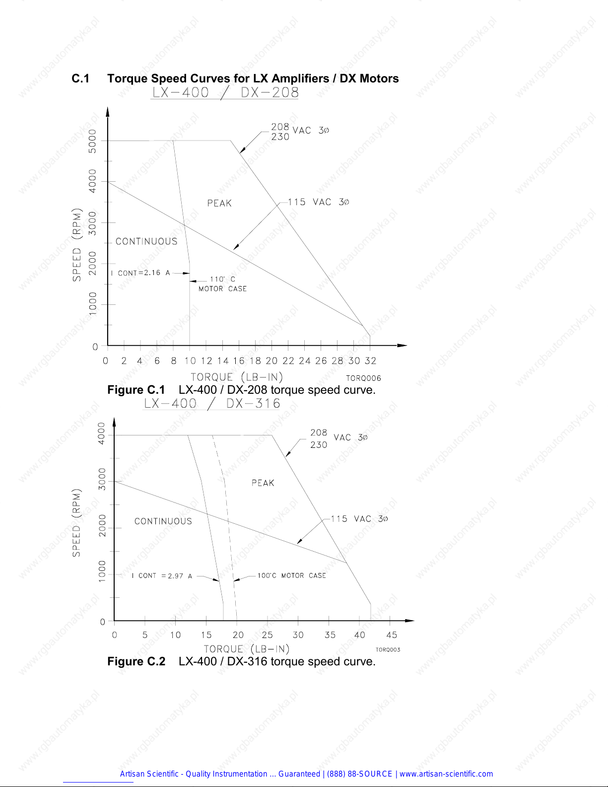
C.1 Torque Speed Curves for LX Amplifiers / DX Motors
Figure C.1 LX-400 / DX-208 torque speed curve.
Figure C.2 LX-400 / DX-316 torque speed curve.
Artisan Scientific - Quality Instrumentation ... Guaranteed | (888) 88-SOURCE | www.artisan-scientific.com
Page 60

Figure C.3 LX-700 / DX-340 torque speed curve.
Figure C.4 LX-700 / DX-455 torque speed curve.
Artisan Scientific - Quality Instrumentation ... Guaranteed | (888) 88-SOURCE | www.artisan-scientific.com
Page 61

Figure C.5 LX-1100 / DX-490 torque speed curve.
Figure C.6 LX-1100 / DX-4120 torque speed curve.
Artisan Scientific - Quality Instrumentation ... Guaranteed | (888) 88-SOURCE | www.artisan-scientific.com
Page 62
D. DX Motor Specifications and Diagrams
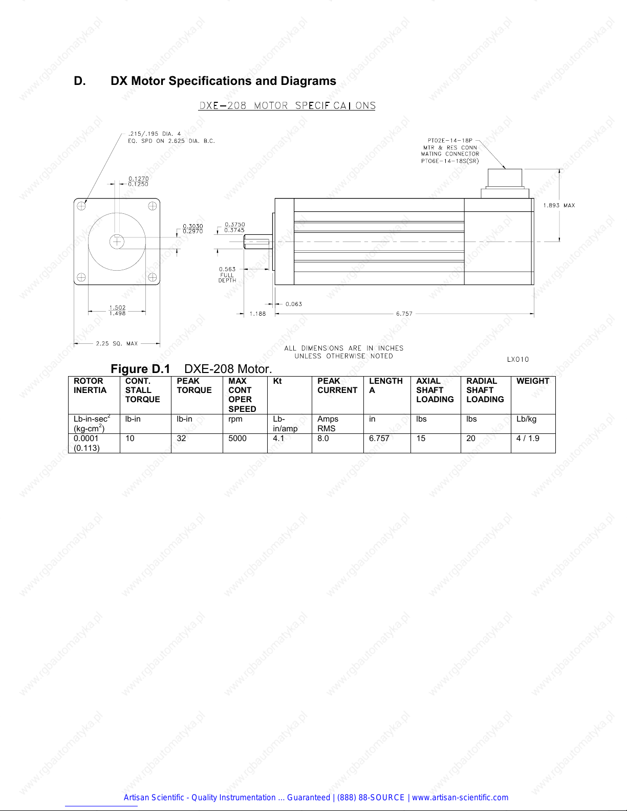
Figure D.1 DXE-208 Motor.
ROTOR
INERTIA
Lb-in-sec
(kg-cm2)
0.0001
(0.113)
CONT.
STALL
TORQUE
2
lb-in lb-in rpm Lb-
10 32 5000 4.1 8.0 6.757 15 20 4 / 1.9
PEAK
TORQUE
MAX
CONT
OPER
SPEED
Kt PEAK
in/amp
CURRENT
Amps
RMS
LENGTHAAXIAL
SHAFT
LOADING
in lbs lbs Lb/kg
RADIAL
SHAFT
LOADING
WEIGHT
Artisan Scientific - Quality Instrumentation ... Guaranteed | (888) 88-SOURCE | www.artisan-scientific.com
Page 63
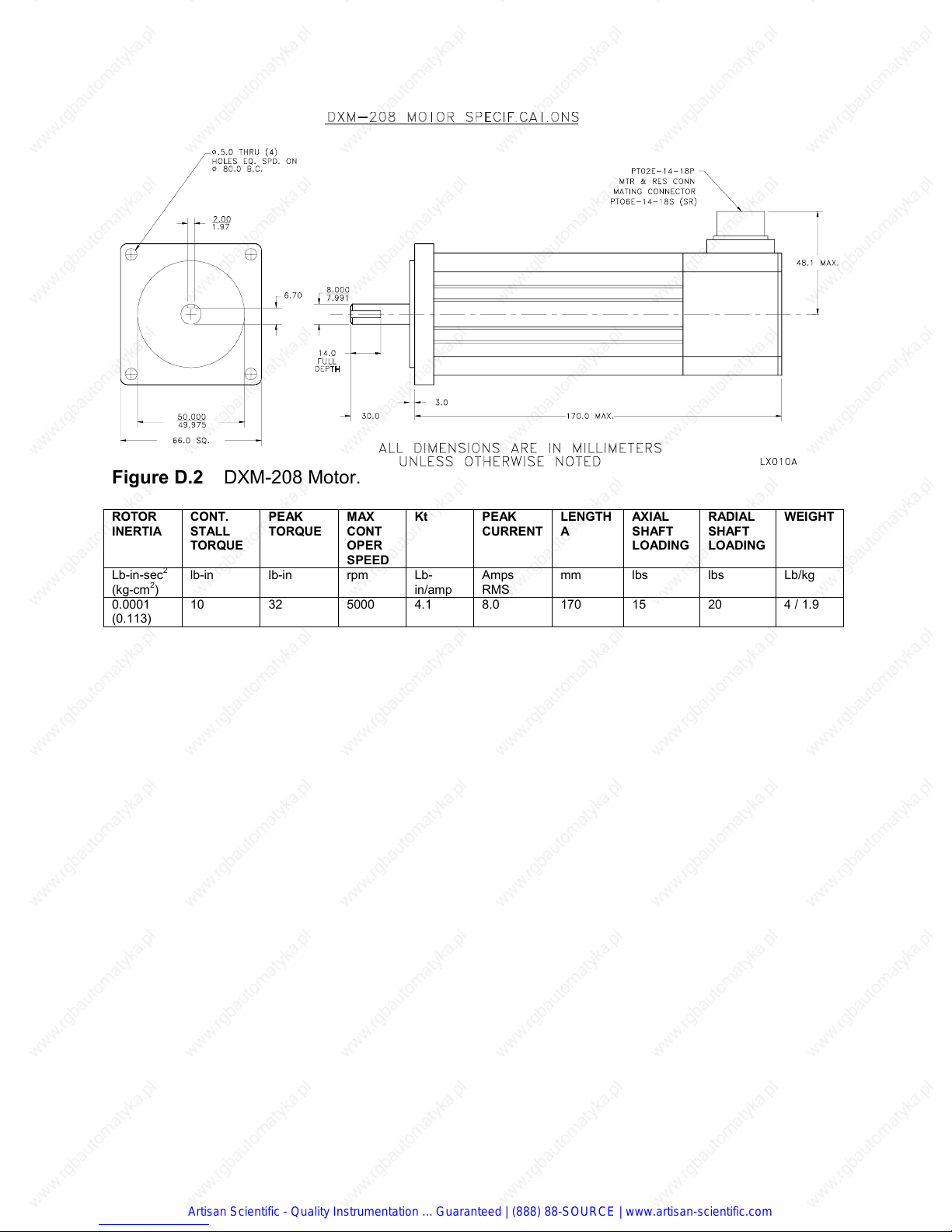
Figure D.2 DXM-208 Motor.
ROTOR
INERTIA
Lb-in-sec
(kg-cm2)
0.0001
(0.113)
CONT.
STALL
TORQUE
2
lb-in lb-in rpm Lb-
10 32 5000 4.1 8.0 170 15 20 4 / 1.9
PEAK
TORQUE
MAX
CONT
OPER
SPEED
Kt PEAK
in/amp
CURRENT
Amps
RMS
LENGTHAAXIAL
SHAFT
LOADING
mm lbs lbs Lb/kg
RADIAL
SHAFT
LOADING
WEIGHT
Artisan Scientific - Quality Instrumentation ... Guaranteed | (888) 88-SOURCE | www.artisan-scientific.com
Page 64
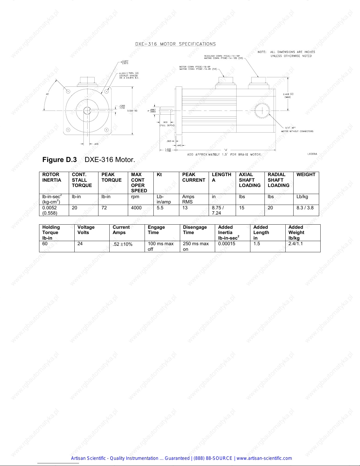
Figure D.3 DXE-316 Motor.
ROTOR
INERTIA
CONT.
STALL
TORQUE
2
lb-in-sec
lb-in lb-in rpm Lb-
(kg-cm2)
0.0052
20 72 4000 5.5 13 8.75 /
(0.558)
Holding
Torque
Voltage
Volts
lb-in
60 24
PEAK
TORQUE
Current
Amps
.52 ±10%
MAX
CONT
OPER
SPEED
Kt PEAK
in/amp
Engage
Time
100 ms max
off
CURRENT
Amps
LENGTHAAXIAL
SHAFT
LOADING
in lbs lbs Lb/kg
RADIAL
SHAFT
LOADING
WEIGHT
RMS
15 20 8.3 / 3.8
7.24
Disengage
Time
Added
Inertia
lb-in-sec
Added
Length
2
in
Added
Weight
lb/kg
250 ms maxon0.00015 1.5 2.4/1.1
Artisan Scientific - Quality Instrumentation ... Guaranteed | (888) 88-SOURCE | www.artisan-scientific.com
Page 65

Figure D.4 DXM-316/340 Motor.
ROTOR
INERTIA
CONT.
STALL
TORQUE
2
lb-in-sec
lb-in lb-in rpm Lb-
(kg-cm2)
0.0052
20 72 4000 5.5 13 223/184 15 20 8.3/3.8
(0.558)
0.0014
50 180 3000 8.3 21.7 301/260 15 20 14.6/6.7
(1.31)
Holding
Torque
Voltage
Volts
lb-in
60 24
PEAK
TORQUE
Current
Amps
.52 ±10%
MAX
CONT
OPER
SPEED
Kt PEAK
in/amp
DXM-316
DXM-340
Engage
Time
100 ms max
off
CURRENT
Amps
RMS
Disengage
Time
LENGTHAAXIAL
SHAFT
LOADING
Mm
NPT/CONN
lbs lbs Lb/kg
Added
Inertia
lb-in-sec
2
Added
Length
mm
RADIAL
SHAFT
LOADING
WEIGHT
Added
Weight
lb/kg
250 ms maxon0.00015 38 2.4/1.1
Artisan Scientific - Quality Instrumentation ... Guaranteed | (888) 88-SOURCE | www.artisan-scientific.com
Page 66

Figure D.5 DXE-455 Motor.
ROTOR
INERTIA
CONT.
STALL
TORQUE
2
lb-in-sec
lb-in lb-in rpm Lb-
(kg-cm2)
0.0026
70 245 3000 8.8 27.8 10.3/8.6 50 100 19.8/9.0
(2.94)
Holding
Torque
Voltage
Volts
lb-in
240 24
PEAK
TORQUE
Current
Amps
.88 ±10%
MAX
CONT
OPER
SPEED
Kt PEAK
in/amp
Engage
Time
100 ms max
off
CURRENT
Amps
RMS
Disengage
Time
LENGTHAAXIAL
SHAFT
LOADING
In
NPT/CONN
lbs lbs Lb/kg
Added
Inertia
lb-in-sec
2
Added
Length
in
RADIAL
SHAFT
LOADING
WEIGHT
Added
Weight
lb/kg
250 ms maxon0.0009 2 5.8/2.6
Artisan Scientific - Quality Instrumentation ... Guaranteed | (888) 88-SOURCE | www.artisan-scientific.com
Page 67

Figure D.6 DXM-455 Motor.
ROTOR
INERTIA
CONT.
STALL
TORQUE
2
lb-in-sec
lb-in lb-in rpm Lb-
(kg-cm2)
0.0026
70 245 3000 8.8 27.8 262/216 50 100 19.8/9.0
(2.94)
Holding
Torque
Voltage
Volts
lb-in
240 24
PEAK
TORQUE
Current
Amps
.88 ±10%
MAX
CONT
OPER
SPEED
Kt PEAK
in/amp
Engage
Time
100 ms max
off
CURRENT
Amps
RMS
Disengage
Time
LENGTHAAXIAL
SHAFT
LOADING
mm
NPT/CONN
lbs lbs Lb/kg
Added
Inertia
lb-in-sec
2
Added
Length
mm
RADIAL
SHAFT
LOADING
WEIGHT
Added
Weight
lb/kg
250 ms maxon0.0009 52 5.8/2.6
Artisan Scientific - Quality Instrumentation ... Guaranteed | (888) 88-SOURCE | www.artisan-scientific.com
Page 68

Figure D.7 DXE-490 / 4120 Motor.
ROTOR
INERTIA
CONT.
STALL
TORQUE
lb-in-sec
2
lb-in lb-in rpm Lb-
(kg-m2)
0.0051
90 315 3000 8.6 36.6 12.8/11.1 50 100 27.5/
(0.00058)
0.0074
120 420 3000 10.5 40.0 15.3/13.6 50 100 38/17.2
(0.00084)
Holding
Torque
Voltage
Volts
lb-in
240 24
PEAK
TORQUE
Current
Amps
.88 ±10%
MAX
CONT
OPER
SPEED
Kt PEAK
in/amp
DXE-490
DXE-4120
Engage
Time
100 ms max
off
CURRENT
Amps
RMS
LENGTHAAXIAL
SHAFT
LOADING
In
NPT/CONN
lbs lbs Lb/kg
RADIAL
SHAFT
LOADING
WEIGHT
11.6
Disengage
Time
Added
Inertia
lb-in-sec
Added
Length
2
in
Added
Weight
lb/kg
250 ms maxon0.0009 2 5.8/2.6
Artisan Scientific - Quality Instrumentation ... Guaranteed | (888) 88-SOURCE | www.artisan-scientific.com
Page 69

Figure D.8 DXM-490 / 4120 Motor.
ROTOR
INERTIA
CONT.
STALL
TORQUE
2
lb-in-sec
lb-in lb-in rpm Lb-
(kg-m2)
0.0051
90 315 3000 8.6 36.6 12.8/11.1 50 100 27.5/
(0.00058)
0.0074
120 420 3000 10.5 40.0 15.3/13.6 50 100 38/17.2
(0.00084)
Holding
Torque
Voltage
Volts
lb-in
240 24
PEAK
TORQUE
Current
Amps
.88 ±10%
MAX
CONT
OPER
SPEED
Kt PEAK
in/amp
DXM-490
DXM-4120
Engage
Time
100 ms max
off
CURRENT
Amps
RMS
LENGTHAAXIAL
SHAFT
LOADING
In
NPT/CONN
lbs lbs Lb/kg
RADIAL
SHAFT
LOADING
WEIGHT
11.6
Disengage
Time
Added
Inertia
lb-in-sec
Added
Length
2
mm
Added
Weight
lb/kg
250 ms maxon0.0009 50 5.8/2.6
Artisan Scientific - Quality Instrumentation ... Guaranteed | (888) 88-SOURCE | www.artisan-scientific.com
Page 70

EMERSON EMC
Subsid.: Emerson Electric Co.
1365 Park Road
Chanhassen, Minnesota 55317-8995
Sales (612) 474-1116 1-800-FX-SERVO
Service (612) 474-8833 (24 hr) FAX: (612) 474-8711
Artisan Scientific - Quality Instrumentation ... Guaranteed | (888) 88-SOURCE | www.artisan-scientific.com
 Loading...