

Page 1
DVS205
Technical Specifications
April 2011
DVS205 Dual-Variable Sensor
The DVS205 Dual-Variable Sensor (DVS205)
provides static pressure and differential pressure
inputs to a FloBoss™ 103, FloBoss 107E, or FloBoss
500-Series Flow Manager. The DVS205
communicates via a serial format with the FloBoss.
Variables
Functionally, the DVS205 is a digital transmitter that
measures two flow-related variables simultaneously:
differential pressure and static pressure. These
variables are continuously available to the FloBoss
unit that polls the DVS205.
Transducer and Electronics
The DVS205 contains a transducer and an
electronics circuit. The transducer uses capacitancecell technology to sense differential pressure and
piezoresistive technology to sense the static
(absolute or gauge) pressure.
The transducer electronics convert the pressure
variables directly into a digital format, allowing
accurate correction and compensation. A
microprocessor linearizes and corrects the raw
pressure signals (from the sensor) using
characterization data stored in non-volatile memory.
The electronics also allow the DVS205 to
communicate with a FloBoss using a Serial
Peripheral Interface (SPI).
Accuracy
Two versions of the DVS205 are available:
205P with reference accuracy of 0.075% of the
full span.
205E with reference accuracy of 0.10% of the
full span.
Mounting
The DVS205 is factory installed on a FloBoss™ 103,
FloBoss 107E, or FloBoss 500-Series Flow Manager
to comply with agency requirements. Attached to the
bottom of the sensor body is a Coplanar™ flange.
This flange allows the DVS205 to mount on an
integral orifice assembly or manifold valve.
Remote Automation Solutions
Website: www.EmersonProcess.com/Remote
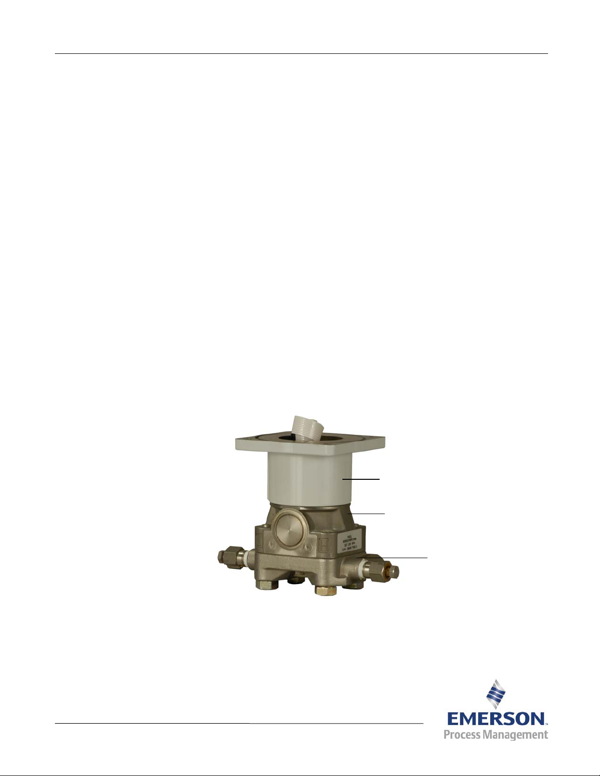
Coupling
Sensor Body
Coplanar
Flange
W8826-A
DVS205 Dual-Variable Sensor
D301569X012
Page 2

DVS205
Technical Specifications
Page 2
DVS205 Multi-Variable Sensor
Differential Pressure Input
Range1 0 to 62.2 kPa (0 to 250" H2O)
0 to 248.8 kPa (0 to 1000" H2O)
Reference Accuracy 205E
Turndowns from 1:1
Stability
Ambient Temperature Effect
per 50°F (28°C)
Spans from 30:1
Static Pressure Effects Zero error
Span error
Over-Pressure Limit 3,626 psi (250 bar) applied on either or both sides without damage to the sensor
Burst Pressure Limit 10,065 psi (694 bar)
205P
±0.125% of URL for five years, with up to ±50°F (28°C) ambient temperature changes
and up to 1000 psi (68,9 bar) line pressure
Spans from 1:1 to
30:1
to 100:1
Turndowns from 1:1
to 10:1 of URL
Turndowns from 10:1
to 100:1 of URL
to 10:1 of URL
Turndowns from 10:1
to 100:1 of URL
±(0.025% URL + 0.125% of span)
±(0.035% URL + 0.175% of span)
±0.05% of URL per 1000 psi (68,9 bar)
±0.20% of DP Reading per 1000 psi (68,9 bar)
±0.10% of span
Not allowed
±0.075% of span
±[0.025 + 0.005(URL/Span)]% of span
Static Pressure Input
Range Either Absolute or Gauge:
0 to 5516 kPa (0 to 800 psia/psig)
0 to 25,000 kPa (0 to 3626 psia/psig)
Reference Accuracy 205E
Turndowns from 1:1
Stability
Ambient Temperature Effect
per 50°F (28°C)
Spans from 30:1
Over-Pressure Limit Same as URL
205P
±0.125% of URL for five years, with up to ±50°F (28°C) ambient temperature changes
Spans from 1:1 to
30:1
to 100:1
Turndowns from 1:1
to 10:1 of URL
Turndowns from 10:1
to 100:1 of URL
to 10:1 of URL
Turndowns from 10:1
to 100:1 of URL
±(0.05% URL + 0.125% of span)
±(0.06% URL + 0.175% of span)
±0.10% of span
Not allowed
±0.075% of span
±[0.03 + 0.0075(URL/Span)]% of span
1. Consult factory for special ranges and materials which may be availa ble. For example, 0 to 6.22 kPa (0 to 25" H2O) at
±0.10% reference accuracy.
Page 3

DVS205
Technical Specifications Page 3
Power
Input at 0 to 75°C (32 to
167°F)
Input at –40 to 0°C (–40 to
32°F)
Physical
Dimensions 120 mm H by 163 mm W by 89 mm D (4.7 in. H by 6.4 in. W by 3.5 in. D)
Weight 2.2 kg (4.9 lb)
Vibration Effect Sensor outputs shall not shift more than +0.1% of upper range limit per g from 5 to 2000
Construction Standard Transducer is all stainless steel construction with silicone fill fluid,
Optional Transducer includes Hastelloy C-276 wetted parts (construction is
Mounting Factory-installed on enclosure of FB103, FB107E, and FB503 units. See respective
Connections Process 1/4-18 NPT on 2-1/8 inch centers (on coplanar flange)
8 to 30 Vdc, 10 mW average
8.5 to 30 Vdc, 10 mW average
Hz in any axis when tested per IEC 770, Section 6.2.14.
316L diaphragms and glass-filled PTFE o-rings.
Coupling is A360 Aluminum with urethane coating.
NACE compliant per MR0103 and ISO15156/MR0175), inert fill fluid.
Coupling is available316 stainless steel.
technical specifications for unit mounting options.
Environmental
Same as the FloBoss unit in which it is installed.
Process Seals per ANSI/ISA
12.27.01
Standard
Meets requirements for a Single Seal device as defined by ANSI/ISA 12.27.01.
Installation must adhere to the following process temperature limits:
Process
Temperature (at
transmitter
isolator flange)
Silicone Fill
Sensor
Inert Fill Sensor –18 to 85°C (0 to 185°F)
Note: Process temperatures above 85°C (185°F) require you to
lower the product’s maximum ambient temperature rating by
a 1.5:1 ratio. To determine the adjusted maximum
temperature rating, perform the following calculation:
Adjusted max T
T
– 85°C (185°F)) * 1.5]
amb
Example:
Adjusted Max T
–40 to 100°C (–40 to 212°F)
= Product Max T
amb
= 75°C – [(95°C – 85°C) * 1.5] = 60°C.
amb
– [(Actual Process
amb
Approvals
Same as the FloBoss unit in which it is installed.
Page 4

DVS205
Technical Specifications
Page 4
Bristol, Inc., Bristol Canada, BBI SA de CV and Emerson Process Management Ltd, Remote Automation Solutions division (UK), are wholly owned subsidiaries of
Emerson Electric Co. doing business as Remote Automation Solutions (“RAS”), a division of Emerson Process Management. FloBoss, ROCLINK, Bristol, Bristol
Babcock, ControlWave, TeleFlow and Helicoid are trademarks of RAS. AMS, PlantWeb and the PlantWeb logo are marks of Emerson Electric Co. The Emerson
logo is a trademark and service mark of the Emerson Electric Co. All other marks are property of their respective owners.
The contents of this publication are presented for informational purposes only. While every effort has been made to ensure informational accuracy, they are not to
be construed as warranties or guarantees, express or implied, regarding the products or services described herein or their use or applicability. RAS reserves the
right to modify or improve the designs or specifications of such products at any time without notice. All sales are governed by RAS’ terms and conditions which
are available upon request. RAS does not assume responsibility for the selection, use or maintenance of any product. Responsibility for proper selection, use and
maintenance of any RAS product remains solely with the purchaser and end-user.
Emerson Process Management
Remote Automation Solutions
Marshalltown, IA 50158 U.S.A.
Houston, TX 77041 U.S.A
Pickering, North Yorkshire UK Y018 7JA
© 2008-2011 Remote Automation Solutions, division of Emerson Process Management. All rights reserved.
 Loading...