

Emerson Carrera CF784BS00, Carrera CF784GES00, Carrera CF784ORB00, Carrera CF784SW00 Owner's Manual
READ AND SAVE THESE INSTRUCTIONS
CARRERA
™
60” Ceiling Fan Owner's Manual
Model Numbers
CF784BS00 -
Brushed Steel
CF784GES00 - Golden Espresso
CF784ORB00 - Oil Rubbed Bronze
CF784SW00 - Satin White
Net Weight: 28.4 Lbs.
Questions, problems, missing parts: Before returning to the store call
Part No. F40BP75010001 Form No. BP7501-1
Revision: 150827 U.L. Model No.: CF784
Emerson Electric Customer Service
8 a.m. - 6 p.m., Eastern, Monday-Friday
1-800-654-3545
www.emersonfans.com
• Español - página 25
• Français - page 49
Table of Contents
Section Page
Safety Instructions . . . . . . . . . . . . . . . . . . . . . . . . . . . . . . . . . . . . . . . . . . .2
1. Unpacking Instructions . . . . . . . . . . . . . . . . . . . . . . . . . . . . . . . . . . . .3-4
2. Electrical Requirements . . . . . . . . . . . . . . . . . . . . . . . . . . . . . . . . . . . .4
3. Ceiling Fan Assembly . . . . . . . . . . . . . . . . . . . . . . . . . . . . . . . . . . .5-11
4. How to Hang Your Ceiling Fan . . . . . . . . . . . . . . . . . . . . . . . . . . . . .12
5. How to Wire Your Ceiling Fan . . . . . . . . . . . . . . . . . . . . . . . . . . . .13-15
6. Using Your Ceiling Fan . . . . . . . . . . . . . . . . . . . . . . . . . . . . . . . . . . . . .16
7. Maintenance . . . . . . . . . . . . . . . . . . . . . . . . . . . . . . . . . . . . . . . . . . . .17
READ AND SAVE THESE INSTRUCTIONS
Safety Instructions
WARNING
TO REDUCE THE RISK OF FIRE, ELECTRICAL SHOCK,
OR INJURY TO PERSONS, OBSERVE THE FOLLOWING:
a. Use this uni t only i n a m anner int ended by th e
manufacturer. If you have questions, contact the
manufacturer.
b. Before servicing or cleaning unit, switch power off at
service panel and lock service panel disconnecting
means to prevent power from being switched on
accidentally. When the service disconnecting means
cannot be locked, securely fasten a warning device,
such as a tag, to the service panel.
1. Read your owner’s manual carefully and keep it for future
reference.
2. Be careful of the fan and blades when cleaning, painting,
or working near the fan. Always turn off the power to the
ceiling fan before servicing.
3. Do not put anything into the fan blades while they are
turning.
4. Do not operate reversing switch until fan blades have
come to a complete stop.
Additional Safety Instructions for Installation
1. To avoid possible shock, be sure electricity is turned off
at the fuse box before wiring, and do not operate fan
without blades.
2. All wiring must be in accordance with the National
El ectr ical Code “ANS I/NF PA 70- 2014” and Loca l
Electrical Codes. Use the National Electrical Code if
Local Codes do not exist. The ceiling fan must be
grounded as a precaution against possible electrical
sh ock. Electri cal ins talla tion should be mad e or
approved by a licensed electrician.
!
Section Page
8. Accessories . . . . . . . . . . . . . . . . . . . . . . . . . . . . . . . . . . . . . . . . . . . . .17
9. Energy Efficient Use of Ceiling Fans . . . . . . . . . . . . . . . . . . . . . . . . .17
10. Repair Parts . . . . . . . . . . . . . . . . . . . . . . . . . . . . . . . . . . . . . . . . .18-19
11. Trouble Shooting . . . . . . . . . . . . . . . . . . . . . . . . . . . . . . . . . . . . . . . .20
Ceiling Fan Limited Warranty . . . . . . . . . . . . . . . . . . . . . . . . . . . . . . . . .23
Spanish . . . . . . . . . . . . . . . . . . . . . . . . . . . . . . . . . . . . . . . . . . . . . . . . . .25
French . . . . . . . . . . . . . . . . . . . . . . . . . . . . . . . . . . . . . . . . . . . . . . . . . . .49
3. The outlet box and joist must be securely mounted and
capable of reliably supporting at least 50 pounds. Use
only U.L. outlet boxes listed as “Acceptable for Fan
Support of 22.7 kg. (50 lbs .) or less”, and use the
mounting screws provided with the outlet box. Most
outlet boxes commonly used for support of light fixtures
are not acceptable for fan support and may need to be
replaced. Consult a qualified electrician if in doubt.
4. The downrod fur nis hed with the fan provides the
minimum recommended floor to fan blade clearance for
an 8 foot ceiling.
5. The fan must be mounted with the fan blades at least
7 feet from the floor to prevent accidental contact with
the fan blades.
6. Follow the recommended instructions for the proper
method of wiring your ceiling fan. If you do not know
enough about electrical wiring, have your fan installed by
a licensed electrician.
WARNING: To reduce the risk of electrical shock, this fan
must be installed with an isolating wall control/switch.
NOTE: This fan is suitable for use with solid-state speed
controls.
WARNING: To avoid fire, shock or injury, do not use an
Emerson or any other brand of control not specifically
approved for this fan.
WARNING: This product is designed to use only those
parts supplied with this product and/or any accessories
designated specifically for use this product by Emerson
Electric Co. Substitution of parts or accessories not
designated for use with this product by Emerson could
result in personal injury or property damage.
WARNING: To reduce the risk of personal injury, do not
bend the blade flange when installing the blade flanges,
balancing the blades or cleaning the fan. Do not insert
foreign objects in between rotating fan blades.
NOTE: All setscrews must be checked and re-tightened
where necessary before installation.
SERIAL NUMBER: DATE CODE:
The serial number of this fan can be found on the nameplate on top of the fan housing. The date code can be
found on the carton and on top of the fan housing, stamped in ink on a white label. You should record this data
above and keep it in a safe place for future use.
U.L. Model No.: CF784
2
A
B
E
F
G
C
D
H
I
1. Unpacking Instructions
7
9
8
5
4
3
2
1
6
12
10
11
WARNING
Do not install or use fan if any part is damaged or
missing. Call Toll-Free for replacement parts:
!
1-800-654-3545
WARNING
This product is designed to use only those parts supplied
with this product and/or any accessories designated
specifically for use with this product by Emerson Electric
Co. Substitution of parts or accessories not designated
for use with this product by Emerson Electric Co. could
result in personal injury or property damage.
!
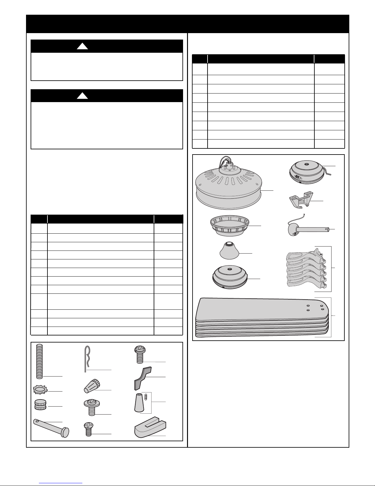
1.1
Check to see that you have received the following parts:
NOTE: If you are uncertain of part description, refer to
exploded view illustration below.
HARDWARE BAG CONTENTS
Part Description Quantity
1 Threaded Studs, #8-32 x 1-1/4” 2
2 Lockwashers, External Tooth #8 2
3 Knurled Knobs, #8-32 2
4 Clevis Pin 1
5 Hairpin Clip 1
6 Wire Connectors 4
7 #10-24 x 10mm Washer Head Blade Screws 21
8 #8-32 x 12mm Flat Head Screw (spare) 1
9 1/4-20 x 14mm Pan Head Screw
with Lockwasher (spare) 1
10 Flange Gasket (spare) 1
11 Die-Cast Pendant and Coupler (1 set) 1
12 Blade Balance Kit 1
PACKAGE CONTENTS
art Description Quantity
P
A Fan Motor Assembly 1
B Ceiling Cover 1
C Motor Coupler Cover 1
D Switch Housing 1
E Switch Housing Assembly 1
F Hanger Bracket 1
G Hanger Ball / 4.5” Downrod Assembly 1
H Fan Blade Flanges 5
I Fan Blades 5
NOTE: Place the parts from the loose parts bags in a
sm all containe r to keep them f rom being l ost.
If any parts are miss ing, call 1-800-654 -3545
for replacement parts before proceeding.
1.2
Remove the fan motor assembly from the protective
plastic bag. Place the fan assembly into the lower
styrofoam with the bottom of the motor facing up.
The upper styrofoam serves as a holder for the fan during
the first stages of assembly.
Please contact 1-800-654-3545 for further assistance
3
emersonfans.com
U.L. Model No.: CF784
1. Unpacking Instructions (Continued)
This Manual Is Designed to Make it as Easy as Possible for You to Assemble,
Install, Operate and Maintain Your Ceiling Fan
Tools Needed for Assembly
One Phillips head screwdriver One stepladder
One wire stripper
Materials
Wiring outlet box and box connectors must be of type
required by the local code. The minimum wire would be a
3-conductor (2-wire with ground) of following size:
Installed Wire Length Wire Size A.W.G.
Up to 50 ft. 14
50-100 ft. 12
2. Electrical Requirements
IMPORTANT: Your ceiling fan will not function
properly, and may be damaged, if used with any wall
dimmer switch or control other than an Emerson
Electric Fan/Light Remote Control.
Your new ceiling fan will require a grounded electrical
supply line of 120 volts AC, 60 Hz, 15 amp circuit.
WARNING
efore assembling your ceiling fan, refer to section on
B
proper method of wiring your fan (page 9). If you feel you
do not have enough wiring knowledge or experience,
have your fan installed by a licensed electrician.
The outlet box must be securely anchored and capable of
withstanding a load of at least 50 pounds.
If your fan is to replace an existing ceiling light fixture, turn
electricity off at the main fuse box at this time and remove
the existing light fixture.
WARNING
!
!
WARNING
To reduce the risk of fire, electric shock, or personal
injury, mount fan to outlet box marked “Acceptable for
Fan Support of 22.7 kg. (50 lbs.) or less”, and use screws
supplied with outlet box. Most outlet boxes commonly
used for support of light fixtures are not acceptable for
fan support and may need to be replaced. Consult a
qualified electrician if in doubt.
WARNING
Turning off wall switch is not sufficient. To avoid possible
electrical shock, be sure electricity is turned off at the
main fuse box before wiring. All wiring must be in
accordance with National and Local codes and the ceiling
fan must be properly grounded as a precaution against
possible electrical shock.
U.L. Model No.: CF784
!
!
To avoid fire or shock, follow all wiring instructions
carefully.
An y elec trica l work not desc ribed in thes e
instructions should be done or approved by a licensed
electrician.
Pl ease ca ll Emer son tec hnical support at
1- 800-654-3545 if you have any questi ons abo ut
installation and operation of this ceiling fan.
4

3. Ceiling Fan Assembly
M
OTOR HUB
N
O
T
E
!
R
e
m
o
v
e
R
u
b
b
e
r
P
a
c
k
i
n
g
M
o
u
n
t
s
A
n
d
D
i
s
c
a
r
d
B
e
f
o
r
e
I
n
s
t
a
l
l
a
t
i
o
n
.
N
O
T
A
!
Q
u
i
t
a
r
L
o
s
S
o
p
o
r
t
e
s
D
e
G
o
m
a
P
a
r
a
E
m
b
a
l
a
J
e
Y
T
i
r
a
r
L
o
s
A
n
t
e
s
D
e
L
a
I
n
s
t
a
l
a
c
i
o
n
.
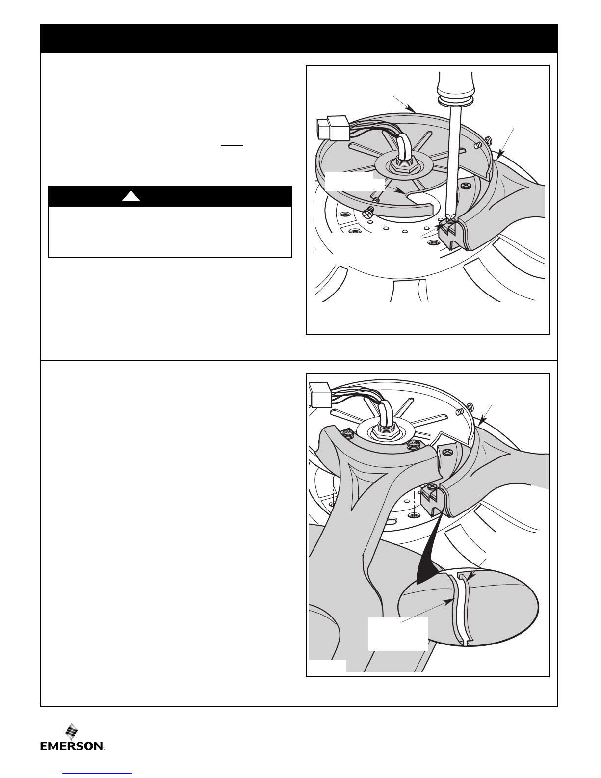
REMOVE SHIPPING
RETAINER
BY REMOVING
5 SCREWS
FLANGE
GASKET
BLADE
FLANGE
BLADE
FLANGE
#10-24 x 10mm WASHER
HEAD BLADE SCREW
(4 per blade/flange)
FAN BLADE
3.1
otate the motor hub to align the hub notch area over
R
each of the five screws which is holding the shipping
retainer to the motor assembly.
One by one unscrew each screw and discard screws and
shipping retainer (Figure 1).
3.2
Verify that the flange gaskets are preinstalled onto the end
of each of the blade flanges (Figure 2).
Figure 1
A spare flange gasket is supplied in the loose parts bag if
required.
3.3
Mount blade flanges to fan blades using four #10-24 x
10mm washer head blade screws (Figure 3).
Figure 2
Figure 3
emersonfans.com
Please contact 1-800-654-3545 for further assistance
5
U.L. Model No.: CF784
3. Ceiling Fan Assembly
MOTOR HUB
BLADE/FLANGE
ASSEMBLY
1/4-20 x 14mm CAPTIVE
PAN HEAD SCREW
(2 per blade/flange assembly)
M
OTOR HUB
N
OTCHED AREA
BLADE/FLANGE
ASSEMBLY
FLANGE
INTERLOCKING
FEATURE
FLANGE
INTERLOCKING
FEATURE
3.4
OTE: Take care not to scratch fan housing when
N
installing blades.
oosely attach one blade/flange assembly to the motor
L
hub by securing the two 1/4-20 x 14mm captive pan head
screws. Make sure the screw s ar e NOT
(Figure 4).
Repeat this procedure for other four blade assemblies.
tightened
WARNING
To reduce the risk of personal injury, do not bend the
bl ade fl ange w hen in stalling th e blad e flan ges,
balancing the blades or cleaning the fan. Do not insert
foreign objects in between rotating fan blades.
!
3.5
NOTE: Each blade/flange assembly must have the
fl ange g asket in place b etween each of the
assemblies.
The blade flanges have an interlocking feature that must
be fully engaged before tightening the screw.
Make sure all the flanges are properly engaged and then
tighten the flange screws (Figure 5).
Figure 4
If one of the flanges does not seat properly on the motor
hub, loosen the adjacent flange screws, re-engage and
reseat the flanges, then tighten the screws again.
U.L. Model No.: CF784
Figure 5
6
SWITCH
HOUSING
#8-32 x 12mm FLAT
HEAD SCREWS (3)
3. Ceiling Fan Assembly
SWITCH HOUSING
ASSEMBLY
CONNECTOR
M
OTOR
C
ONNECTOR
PULL CHAIN SWITCH
SWITCH HOUSING
ASSEMBLY
SWITCH HOUSING
ADAPTER
SWITCH
HOUSING
ASSEMBLY
REINSTALL THE #8-32 x 12mm
FLAT HEAD SCREWS (3)
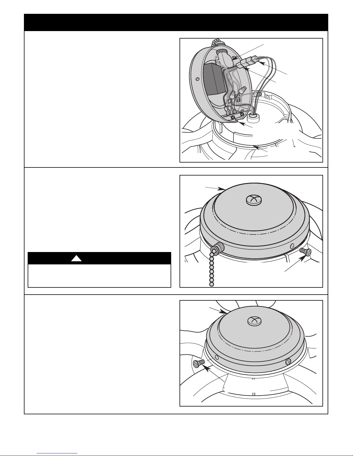
Installation of Switch Housing
Assembly for Manual Control
3.6
Remove and retain the three #8-32 x 12mm flat head
screws from the switch housing plate.
Engage the connector of the switch housing assembly with
the motor connector (Figure 6).
The two connectors are keyed and color-coded and must
be mated correctly (color-to-color) before they can be
engaged.
Make sure the connector latch closes properly.
Installation of Switch Housing
Assembly for Manual Control
Figure 6
3.7
Carefully tuck all wires and connectors under the switch
housing assembly.
Secure the switch housing assembly by reinstalling the
three #8-32 x 12mm flat head screws (previously removed)
(Figure 7).
Proceed to Ceiling Fan Assembly, Step 3.9.
WARNING
To avoid possible fire or shock, do not pinch wires
between the switch housing assembly and the switch
housing plate.
!
Installation of Switch Housing for
Accessory Control
If Emerson Accessory RF Control is to be used, install
the accessory control switch housing.
3.8
Remove and retain the three #8-32 x 12mm flat head
screws from the switch housing plate.
Position the switch housing on the switch housing adapter
and align the holes in the switch housing with the holes in
the adapter.
Secure the switch housing by reinstalling the three
#8-32 x 12mm flat head screws (previously removed)
(Figure 8).
Proceed to Ceiling Fan Assembly, Step 3.9.
Figure 7
Figure 8
Please contact 1-800-654-3545 for further assistance
7
emersonfans.com
U.L. Model No.: CF784
3. Ceiling Fan Assembly (continued)
STYROFOAM
PARTIALLY ASSEMBLED
CEILING FAN
SETSCREW (LOOSENED)
HANGER BALL
4.5" DOWNROD
PIN
GREEN GROUND WIRE
THREE 80" MOTOR LEADS (UNTWISTED)
4.5" DOWNROD
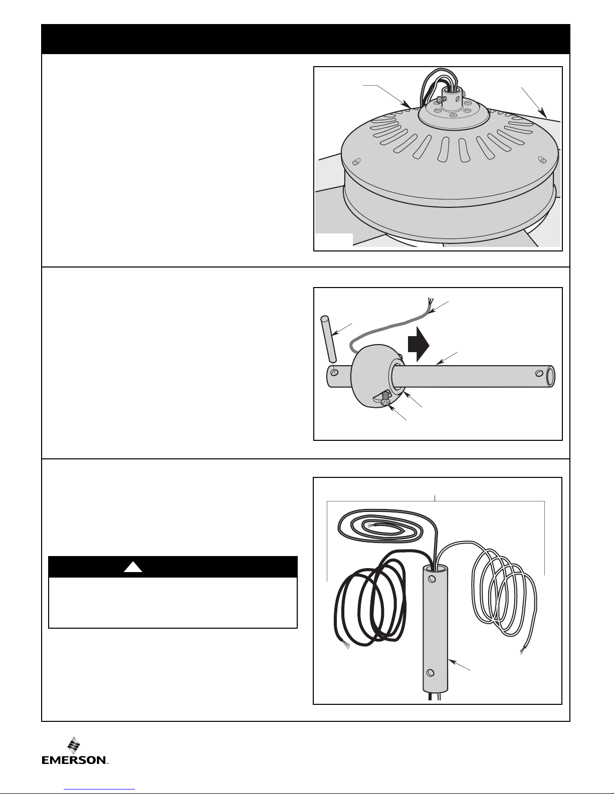
3.9
Turn the partially assembled ceiling fan right side up in
preparation for final assembly.
Carefully place the partially assembled ceiling fan on the
tyrofoam being careful not to bend the ceiling fan blades
s
(Figure 9).
3.10
Remove the hanger ball from the 4.5” downrod by
loosening the setscrew in the hanger ball until the ball falls
freely down the downrod (Figure 10).
Remove the pin from the downrod, then remove the
hanger ball.
Retain the pin and hanger ball for reinstallation in
Step 3.15.
NOTE: Do not loosen the screw holding the green
ground wire.
Figure 9
Figure 10
3.11
Separate, untwist and unkink the three 80” motor leads.
Route the 80” black and white motor leads through the
4.5” downrod (Figure 11).
WARNING
It is critical that the clevis pin in the motor coupling is
properly installed and the setscrews securely tightened.
Failure to verify that the pin and setscrews are properly
installed could result in the fan falling.
U.L. Model No.: CF784
!
Figure 11
8
 Loading...