

Page 1

READ AND SAVE THESE INSTRUCTIONS
BUILDER Series
52” Ceiling Fan Owner's Manual
Model Numbers
CF700BS09
CF700ORB09 - Oil Rubbed Bronze
CF700WW09 - Appliance White
Net Weight: 14.4 Lbs.
Questions, problems, missing parts: Before returning to the store call
Emerson Electric Customer Service
8 a.m. - 6 p.m., Eastern, Monday-Friday
- Brushed Steel
Part No. F40BP73120004 Form No. BP7312-4
Revision: 150226 U.L. Model No.: 52-ANT
1-800-654-3545
www.emersonfans.com
• Español - página 25
• Français - page 49
Page 2
Table of Contents
Section Page
Safety Instructions . . . . . . . . . . . . . . . . . . . . . . . . . . . .2
1. Unpacking Instructions . . . . . . . . . . . . . . . . . . . . .3-4
. Electrical Requirements . . . . . . . . . . . . . . . . . . . . .4
2
3. Ceiling Fan Assembly . . . . . . . . . . . . . . . . . . . .5-10
4. How to Hang Your Ceiling Fan . . . . . . . . . . . .11-12
5. How to Wire Your Ceiling Fan . . . . . . . . . . . . .13-15
6. Using Your Ceiling Fan . . . . . . . . . . . . . . . . . . . . .16
7. Maintenance . . . . . . . . . . . . . . . . . . . . . . . . . . . . . .17
READ AND SAVE THESE INSTRUCTIONS
Safety Instructions
WARNING
TO REDUCE THE RISK OF FIRE, ELECTRICAL SHOCK,
OR IN JURY TO P ERSO NS, OB SERV E T H E
FOLLOWING:
a. Use this unit on ly in a manner intended by the
manufacturer. If you have questions, contact the
manufacturer.
b. Before servicing or cleaning unit, switch power off
at servi c e pan el and l ock s ervi c e pan el
disconnecting means to prevent power from being
swi tche d on a ccid enta lly. When the s ervi ce
disconnecting means cannot be locked, securely
fa sten a war ning d evice, su ch as a tag, to the
service panel.
1. Read your owner’s manual carefully and keep it for
future reference.
2. Be careful with the fan and blades when cleaning,
painting, or working near the fan. Always turn off the
power to the ceiling fan before servicing.
3. Do not put anything into the fan blades while they are
turning.
4. Do not operate reversing switch until fan blades have
come to a complete stop.
Additional Safety Instructions for
Installation
1. To avoid possible shock, be sure electricity is turned
off at the fuse box before wiring, and do not operate
fan without blades.
2. All wiring must be in accordance with the National
El ectrical Cod e “ANSI /NFPA 7 0-201 4” and Lo cal
Electrical Codes. Use the National Electrical Code if
Local Codes do not exist. The ceiling fan must be
grounded as a precaution against possible electrical
sh ock. El ectri cal install ation sho uld be made or
approved by a licensed electrician.
!
Section Page
8. Accessories . . . . . . . . . . . . . . . . . . . . . . . . . . . . . .17
9. Repair Parts . . . . . . . . . . . . . . . . . . . . . . . . . . .18-19
0. Trouble Shooting . . . . . . . . . . . . . . . . . . . . . . . .20
1
11. Energy Efficient Use of Ceiling Fans . . . . . . . . .21
Ceiling Fan Limited Warranty . . . . . . . . . . . . . . . . . .23
Spanish . . . . . . . . . . . . . . . . . . . . . . . . . . . . . . . . . . .25
French . . . . . . . . . . . . . . . . . . . . . . . . . . . . . . . . . . . .49
3. The outlet box and joist must be securely mounted
and capable of reliably supporting at least 50 pounds.
Use only U.L. outlet boxes listed as “Acceptable for
Fan Support of 22.7 kg. (50 lbs.) or less”, and use the
mou ntin g scre w s pro v ide d w ith th e o utle t box.
Most outlet boxes commonly used for support of light
fixtures are not acceptable for fan support and may
need to be replaced. Consult a qualified electrician if
in doubt.
4. The dow nro d fur nish ed wi th the fan pr oves t he
minimum recommended floor to fan blade clearance
for an 8 foot ceiling.
5. The fan must be mounted with the fan blades at least
7 feet from the floor to prevent accidental contact with
the fan blades.
6. Follow the recommended instructions for the proper
method of wiring your ceiling fan. If you do not know
enough about electrical wiring, have your fan installed
by a licensed electrician.
WARNING: To reduce the risk of electrical shock, this
fan must b e install ed with an isolating wall control/
switch.
WARNING: To avoid fire, shock or injury, do not use an
Emerson or any other brand of control not specifically
approved for this fan.
WARNING: This product is designed to use only those
parts supplied with this product and/or any accessories
designated specifically for use this product by Emerson
Electric Co. Substitution of parts or accessories not
designated for use with this product by Emerson could
result in personal injury or property damage.
WARNING: To reduce the risk of personal injury, do not
bend the blade flange when installing the blade flanges,
balancing the blades or cleaning the fan. Do not insert
foreign objects in between rotating fan blades.
NOTE: All setscrews must be checked and re-tightened
where necessary before installation.
DATE CODE:
The date code of this fan may be found on the box, stamped in ink on a white label. You should
record this data above and keep it in a safe place for future use.
U.L. Model No.: 52-ANT
2
Page 3
E
D
G
F
C
B
A
1. Unpacking Instructions
4
10
9
8
1
23
5
7
6
WARNING
Do not install or use fan if any part is damaged or
missing. Call Toll-Free for replacement parts:
!
1-800-654-3545
WARNING
This prod uc t is designed to us e only those parts
supplied with this product and/or any accessories
designated specifically for use with this product by
Eme rson E lec t ric C o. Su bsti tuti o n of p arts or
accessories not designated for use with this product
by Emerson Electric Co. could result in personal injury
or property damage.
!
1.1
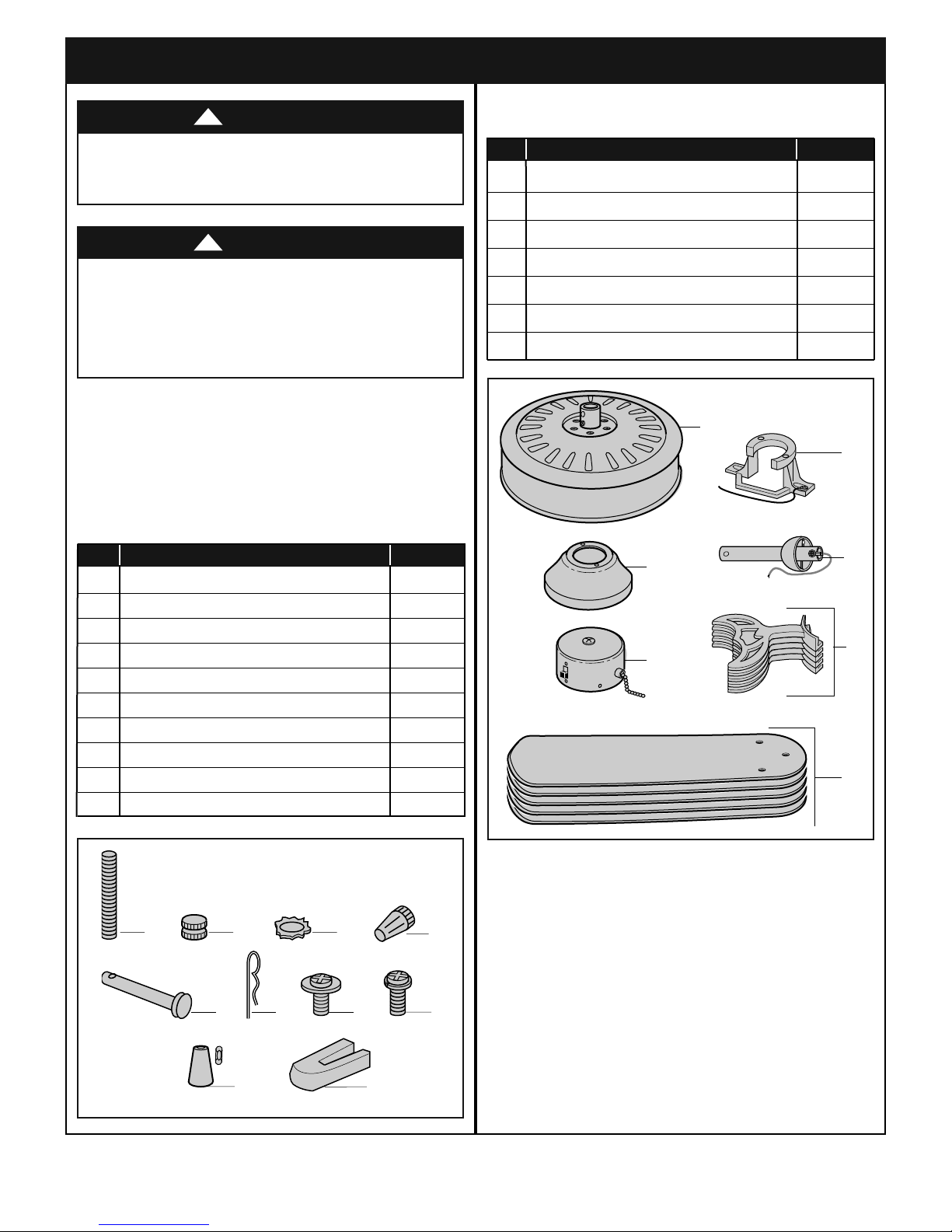
Check to see that you have received the following parts:
NOTE: If you are uncertain of part description, refer
to exploded view illustration below.
HARDWARE BAG CONTENTS
Part Description Quantity
1 Threaded Studs, #8-32 x 1-1/4” 2
2 Knurled Knobs, #8-32 2
3 Lockwashers, External Tooth #8 2
4 Wire Connectors 3
5 Clevis Pin 1
6 Hairpin Clip 1
7 M5 x 6mm Washer Head Screws 16
8 M6 x 12mm Flange Screw with Lockwasher 11
9 Wood Ball Pendant & Coupling 1
10 Blade Balance Kit 1
PACKAGE CONTENTS
Part Description Quantity
A Fan Motor Assembly 1
B Ceiling Cover 1
C Switch Housing Assembly 1
D Hanger Bracket 1
E Hanger Ball/4.5” Downrod Assembly 1
F Fan Blade Flanges 5
G Fan Blades 5
NOTE: Place the parts from the loose parts bags in
a small container to keep them from being lost.
If any parts are mis sing, cal l 1- 8 00-65 4 -3545
for replacement parts before proceeding.
1.2
Remo v e the fan as sembly from t he pro t ectiv e
plastic bag. Place the fan assembly into the upper
styrofoam with the top of the motor facing up.
The upper styrofoam serves as a holder for the fan
during the first stages of assembly.
emersonfans.com
Please contact 1-800-654-3545 for further assistance
3
U.L. Model No.: 52-ANT
Page 4
1. Unpacking Instructions (Continued)
This Manual Is Designed to Make it as Easy as Possible for You to Assemble,
Install, Operate and Maintain Your Ceiling Fan
Tools Needed for Assembly
One Phillips head screwdriver One stepladder
One Standard screwdriver One wire stripper
Materials
Wiring outlet box and box connectors must be of type
required by the local code. The minimum wire would be
a 3-conductor (2-wire with ground) of following size:
Installed Wire Length Wire Size A.W.G.
Up to 50 ft. 14
50-100 ft. 12
2. Electrical Requirements
WARNING
Before assembling your ceiling fan, refer to section on
proper method of wiring your fan (page 12). If you feel
you do no t hav e eno ugh w irin g kno wled ge or
experience, have your fan installed by a licensed
electrician.
!
Controls Sold Separately
SW46 Wall Control and SW90 Wall Control (both sold
separately) may be used with this 52” Builder Series
Ceiling Fan. Controls are recommended for indoor use
only. This 52” Builder Series Ceiling Fan is light fixture
adaptable (sold separately).
Your new ceiling fan will require a grounded electrical
supply line of 120 volts AC, 60 Hz, 15 amp circuit.
WARNING
To reduce the risk of fire, electric shock, or personal
injury, mount fan to outlet box marked “Acceptable for
Fan Support of 22.7 kg. (50 lbs.) or less”, and use
screws supplied with outlet box. Most outlet boxes
commonly used for support of light fixtures are not
acc epta ble for f an sup port a nd may n eed to be
replaced. Consult a qualified electrician if in doubt.
WARNING
Turning off wall switch is not sufficient. To avoid
possible electrical shock, be sure electricity is turned
off at the main fuse box before wiring. All wiring must
be in accordance with National and Local codes and
the c eil ing fa n must b e pro perl y gro unde d as a
precaution against possible electrical shock.
!
!
The outlet box must be securely anchored and capable
of withstanding a load of at least 50 pounds.
If your fan is to replace an existing ceiling light fixture,
turn electricity off at the main fuse box at this time and
remove the existing light fixture.
WARNING
To avoid fire or shock, follow all wiring instructions
carefully.
Any e lect rica l work n ot de s cri b ed in the s e
instructions should be done or approved by a licensed
electrician.
Plea s e c all Emer s on techni c al suppo r t a t
1-800-654-3545 if you have a ny questions about
installation and operation of this ceiling fan.
!
U.L. Model No.: 52-ANT
4
Page 5
CEILING
COVER
42" MOTOR
LEADS
3. Ceiling Fan Assembly
HANGER BALL/
4.5" DOWNROD
ASSEMBLY
42" MOTOR
LEADS
3.1
Disconnect electrical power to the branch circuit at the
circuit breaker or fuse box before attempting to install
he ceiling fan mounting plate on the outlet box.
t
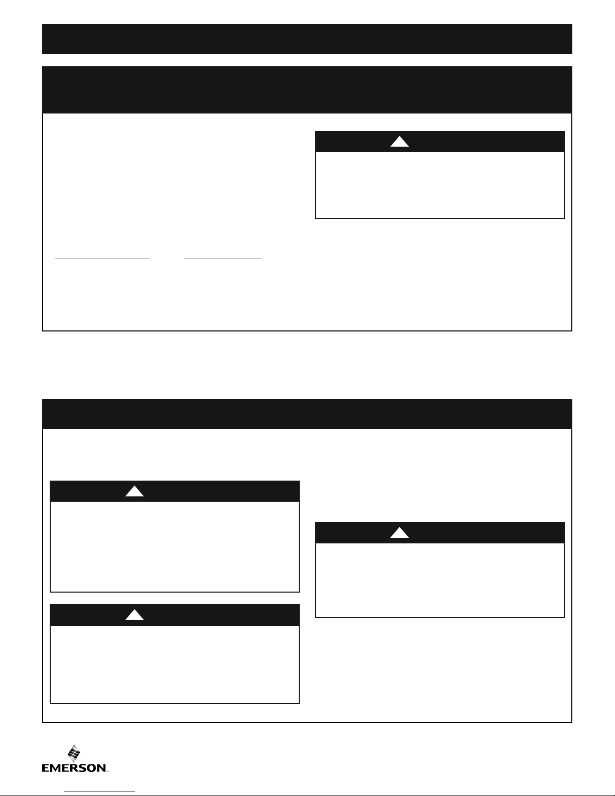
3.2
Pass the three 42" motor leads through the opening in
the ceiling cover.
Be sure the cover is oriented correctly (Figure 1).
Turning off wall switch is not sufficient. To avoid
ossible electrical shock, be sure electricity is turned
p
off at the main fuse box before wiring. All wiring must
be in accordance with National and Local codes and
the c eil ing fa n must b e pro perl y gro unde d as a
precaution against possible electrical shock.
!
WARNING
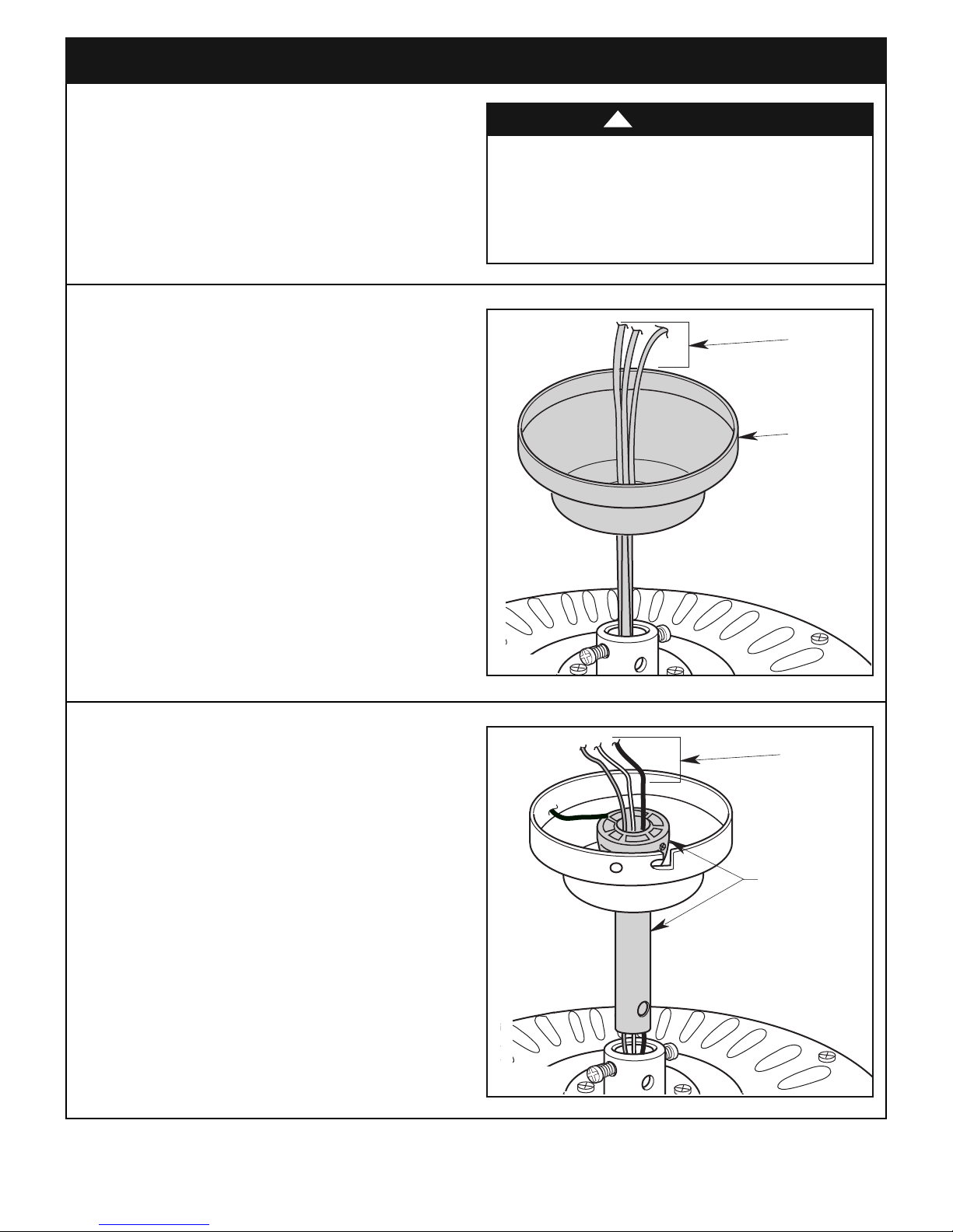
3.3
Separate, untwist and unkink the three 42" motor
leads.
Rout e the 42" mo t or leads th rough th e hanger
ball/downrod assembly (Figure 2).
Figure 1
Figure 2
emersonfans.com
Please contact 1-800-654-3545 for further assistance
5
U.L. Model No.: 52-ANT
Page 6
D
OWNROD
CLEVIS
PIN
HAIRPIN
CLIP
MOTOR
COUPLING
HAIRPIN
C
LIP
C
LEVIS
PIN
LOOSEN
SETSCREWS (2)
3. Ceiling Fan Assembly (Continued)
RETIGHTEN
SETSCREW
MOTOR COUPLING
RETIGHTEN
SETSCREW
DOWNROD
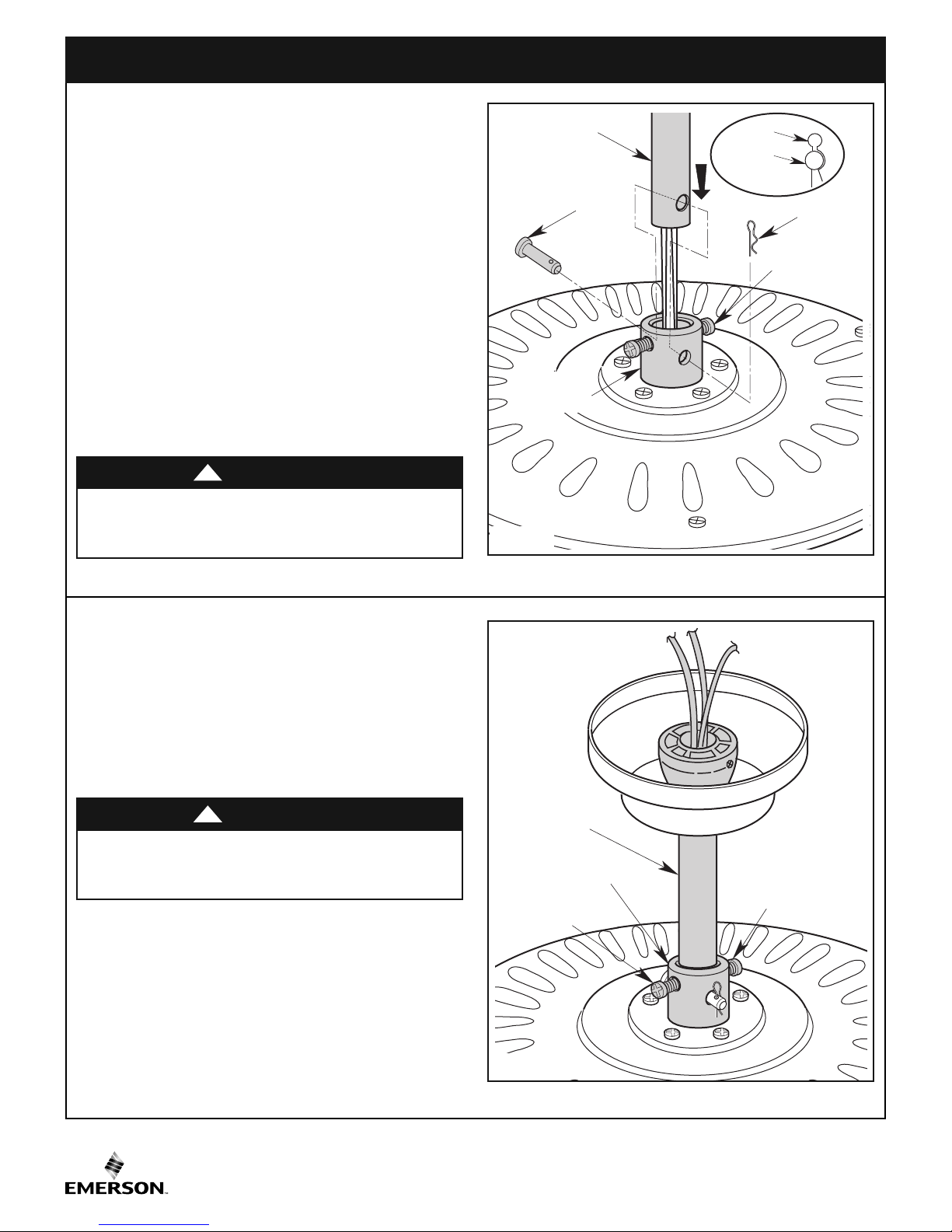
3.4
Loosen the two setscrews in the motor coupling.
Place the hanger ball/4.5” downrod assembly into the
motor coupling, aligning the clevis pin holes in the
downrod with the holes in the motor coupling (Figure 3).
The clevis pin must go through the holes in the motor
coupling and the holes in the downrod.
Be sure to push the straight leg of the hairpin clip
through the hole near the end of the clevis pin until the
curved portion of the hairpin clip snaps around the
clevis pin.
The hairpin clip must be properly installed to prevent
the clevis pin from working loose.
Pull on the hanger ball to make sure the clevis pin is
properly installed.
WARNING
It is critical that the clevis pin in the motor coupling is
properly installed. Failure to verify that the pin is
properly installed could result in the fan falling.
!
3.5
While pulling up on the hanger ball, retighten the two
setscrews (previously loosened) in the motor coupling
to secure the hanger ball/4.5” downrod assembly into
place (Figure 4).
NOTE: The setscrews must be properly installed as
described above, or fan wobble could result.
WARNING
It is critical that the setscrews are securely tightened.
Fa ilure t o verif y th at th e se tsc rews ar e prope rly
installed could result in the fan falling.
!
Figure 3
U.L. Model No.: 52-ANT
Figure 4
6
Page 7

STYROFOAM
PARTIALLY ASSEMBLED
CEILING FAN
SPACER ATTACHMENT SCREW
SHIPPING SPACER
3. Ceiling Fan Assembly (Continued)
HANGER BALL/
DOWNROD
ASSEMBLY
6 to 9
INCHES
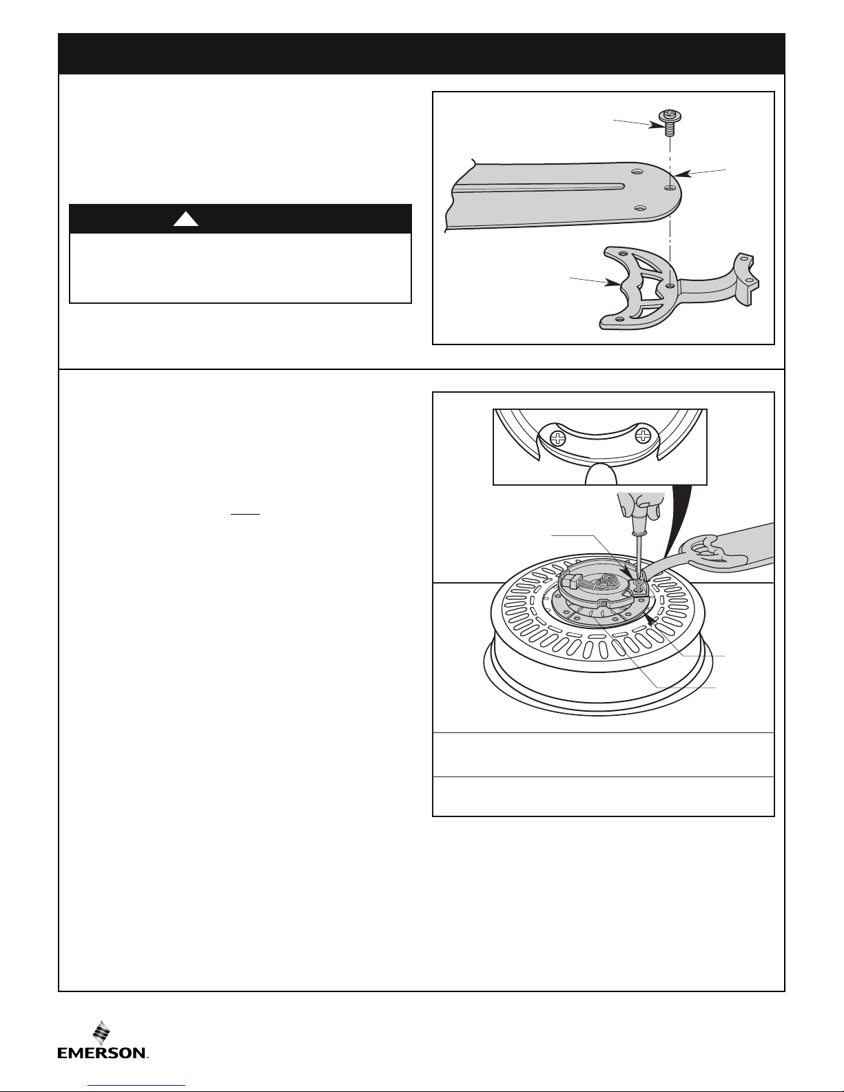
3.6
The fan comes with blue, black and white leads that are
42” long.
Measure up approximately 6 to 9-inches above top of
hanger ball/4.5” downrod assembly (Figure 5).
Cut off excess leads and strip back insulation 1/2-inch
from end of leads.
3.7
Carefully turn the partially assembled ceiling fan over
and place it on the styrofoam for final preparation
(Figure 6).
Figure 5
3.8
Remo v e the sh i pping s p acers a n d the spa c er
attachment screws from the motor before installation of
blade assemblies (Figure 7).
Discard the spacers and spacer screws.
7
Figure 6
Figure 7
emersonfans.com
Please contact 1-800-654-3545 for further assistance
U.L. Model No.: 52-ANT
Page 8
3. Ceiling Fan Assembly (Continued)
M6 x 12mm FLANGE SCREWS
WITH LOCKWASHERS
(2 per blade assembly)
MOTOR
HUB
SWITCH
HOUSING
PLATE
FAN
BLADE
B
LADE FLANGE
M5 x 6mm WASHER HEAD
BLADE SCREW (3)
3.9
Mount the blade flange to the fan blade using three
M5 x 6mm washer head screws (supplied) (Figure 8).
Repeat this procedure for other four fan blades and
blade flanges.
WARNING
To reduce the risk of personal injury, do not bend the
bla de fla n ge when ins tall ing the b lade f l ange s,
alancing the blades or cleaning the fan. Do not insert
b
foreign objects in between rotating fan blades
!
3.10
Rotate the motor hub until the flange screw hole is next
to the cutout in the switch housing plate.
Attach one blade assembly to the motor hub using two
M6 x 12mm flange screws with lockwashers in flange.
Make sure the screws are NOT tightened. (Figure 9).
Repe a t this pr ocedu r e for th e other fo ur blad e
assemblies.
NOTE: The blade flanges have an int erlocki ng
feat u re tha t m ust be f u lly eng a ged be f ore
tightening the screws. Make sure all the flanges are
pr ope rly engaged and then tighten the flange
screws. If one of the flanges does not seat properly
on th e mot or hub, loosen t he adjacent flange
screws, re-engage and reseat the flanges, then
tighten the screws again.
Figure 8
U.L. Model No.: 52-ANT
Figure 9
8
Page 9

3. Ceiling Fan Assembly (Continued)
SWITCH HOUSING
MOUNTING SCREWS (3)
SWITCH HOUSING
MOUNTING PLATE
SWITCH HOUSING
ASSEMBLY
SWITCH HOUSING
CONNECTOR
MOTOR CONNECTOR
3.11
Remove the three switch housing mounting screws
(Figure 10) from the switch housing plate.
Retain the screws for future use in Step 3.13.
NOTE: If you are using an Emerson light fixture
with your fan. Remove the screw plug from the
bottom of the switch housing cover and install the
light in accor dan ce with the li ght k it Owner's
Manual. Make light kit electrical connections to blue
and white leads marked “For Light” in the switch
housing. Follow light kit instructions for wiring and
installation . Then rein sta ll swi tch ho using as
outlined above.
3.12
Engage the connector of the switch housing assembly
with the motor connector (Figure 11).
Figure 10
The two connectors are keyed and color-coded and
must be mated correctly (color-to-color) before they can
be engaged.
Make sure the connector latch closes properly.
Figure 11
emersonfans.com
Please contact 1-800-654-3545 for further assistance
9
U.L. Model No.: 52-ANT
Page 10

3. Ceiling Fan Assembly (Continued)
SWITCH
HOUSING
ASSEMBLY
MOUNTING
SCREWS (3)
3.13
osition the switch housing assembly on the switch
P
housing plate and align the holes in the switch housing
assembly with the holes in the plate.
Secure the switch housing assembly by reinstalling
the t hree m ount ing screws (p revious ly rem oved )
(Figure 12).
NO TE: Do not pin ch wires betwee n the switch
housing assembly and the switch housing plate.
You have now completed the assembly of your new
ceiling fan. You can now proceed with hanging and
wiring your fan.
Figure 12
U.L. Model No.: 52-ANT
10
Page 11

TWO SCREWS
SUPPLIED WITH
OUTLET BOX
HANGER BRACKET
ANTI-ROTATION TAB
OUTLET BOX
FLOOR
AT LEAST
7
'
CEILING
4. How to Hang Your Ceiling Fan
WARNING
The fan must be hung with at least 7' of clearance from
floor to blades (Figure 12).
WARNING
The outlet box and joist must be securely mounted and
capable of supporting at least 50 lbs. Use only a U.L.
outlet box listed as “Acceptable for Fan Support of
22.7 kg. (50 lbs.) or less”.
!
!
Figure 13
WARNING
To reduce the risk of fire, electric shock, or personal
injury, mount fan to outlet box marked “Acceptable for
Fan Support of 22.7 kg. (50 lbs.) or less”, and use
screws supplied with outlet box. Most outlet boxes
commonly used for support of light fixtures are not
acc epta ble for f an sup port a nd may n eed to be
replaced. Consult a qualified electrician if in doubt.
!
4.1
Securely attach the hanger bracket to the outlet box
using the two screws supplied with the outlet box.
(Figure 14).
WARNING
Hanger bracket must seat firmly against outlet box. If
the outlet box is recessed, remove wall board until
bracket contacts box. If bracket and/or outlet box are
not securely attached, the fan could wobble or fall.
!
11
Figure 14
emersonfans.com
Please contact 1-800-654-3545 for further assistance
U.L. Model No.: 52-ANT
Page 12

4. How to Hang Your Ceiling Fan (Continued)
OUTLET
BOX
HANGER
BRACKET
HANGER BALL/
DOWNROD
ASSEMBLY
NOTE: SUPPLY WIRES AND FAN WIRES OMITTED FOR CLARITY.
HANGER BRACKET
HANGER BALL
HANGER BALL
GROOVE
ANTI-ROTATION
TAB
4.2
aref u lly lif t the fan and se a t the han g er ball/
C
downrod assembly on the hanger bracket that was just
attached to the outlet box (Figure 15). Be sure the
groove in the ball is engaged with the anti-rotation tab
on the hanger bracket (Figure 15).
WARNING
Failure to seat tab in groove could cause damage to
electrical wires and possible shock or fire hazard.
WARNING
To avoid possible fire or shock, do not pinch wires
be twe en the h ang er ball/downrod a sse mbl y and
hanger bracket.
!
!
Figure 15
U.L. Model No.: 52-ANT
12
Page 13

LISTED WIRE
CONNECTOR
SUPPLY WHITE
(NEUTRAL)
FAN MOTOR
WHITE WIRE
5. How to Wire Your Ceiling Fan
GROUND
CONDUCTOR SUPPLY
L
ISTED WIRE
CONNECTOR
GREEN WIRE
(GROUND) FROM
HANGER BRACKET
GREEN WIRE
(GROUND) FROM
HANGER BALL
If you feel that you do not have enough electrical
wiring knowledge or experience, have your fan
installed by a licensed electrician.
WARNING
To avoid possible electrical shock, be sure electricity
is turned off at the main fuse box before wiring.
NOTE: If you are not sure if the outlet box is grounded,
ontact a licensed electrician for advice, as it must be
c
grounded for safe operation.
!
5.1
Connect the green grounding lead from the hanger ball
and the green grounding lead from the hanger bracket
to the grounding conductor of supply (this may be a
bare wire or wir e with gree n colored insu lat ion ).
Securely connect wires with wire connectors (supplied)
(Figure 16).
WARNING
This prod uc t is designed to us e only those parts
supplied with this product and/or any accessories
designated specifically for use with this product by
Eme rson E lec t ric C o. Su bsti tuti o n of p arts or
accessories not designated for use with this product
by Emerson Electric Co. could result in personal injury
or property damage.
!
Figure 16
5.2
Securely connect the fan motor white wire to the supply
white (neutral) wire using wire connector (supplied)
(Figure 17).
13
Figure 17
emersonfans.com
Please contact 1-800-654-3545 for further assistance
U.L. Model No.: 52-ANT
Page 14

5. How to Wire Your Ceiling Fan (Continued)
F
AN MOTOR
BLACK WIRE
SUPPLY
BLACK
(HOT)
FAN MOTOR
BLUE WIRE
LISTED WIRE
CONNECTOR
BLACK &
BLUE WIRES
WHITE WIRES
GREEN
WIRES
5.3
Securely connect the fan motor black wire and blue
wire s to t h e supp l y blac k (hot) wire u s ing w i re
connector (supplied) (Figure 18).
5.4
After connections have been made, turn leads upward
and carefully push leads into the outlet box, with the
white and green leads on one side of the outlet box and
position the black and blue leads on the other side of
the outlet box (Figure 19).
Figure 18
WARNING
Check to see that all connections are tight, including
ground, and that no bare wire is visible at the wire
con nec t ors , exce pt for t he grou nd wir e. Do no t
operate fan until blades are in place. Noise and fan
damage could result.
!
Figure 19
U.L. Model No.: 52-ANT
14
Page 15

5. How to Wire Your Ceiling Fan (Continued)
THREADED
STUDS (2)
5.5
Screw the two threaded studs (su pplied) into t he
tapped holes in the hanger bracket (Figure 20).
5.6
Lift the ceiling cover up to the threaded studs and turn
until studs protrude through the holes in the ceiling
cover (Figure 21).
Figure 20
CEILING COVER
5.7
Secure the ceiling cover in place by sliding lockwashers
over the threaded studs and installing the two knurled
knobs (supplied). (Figure 21).
Tighten the knurled knobs securely until the ceiling
cover fits snugly against the ceiling and the hole in the
ceiling cover is clear of the downrod.
WARNING
To avoid possible fire or shock, make sure that the
electrical wires are completely inside the outlet box and
not pinched between the ceiling cover and the ceiling.
!
THREADED STUDS (2)
LOCKWASHERS (2)
KNURLED KNOBS (2)
Figure 21
15
emersonfans.com
Please contact 1-800-654-3545 for further assistance
U.L. Model No.: 52-ANT
Page 16

6. Using Your Ceiling Fan
REVERSING
SWITCH
SWITCH
HOUSING
ASSEMBLY
3-SPEED SWITCH
PULL CHAIN
WOODEN PENDANT
CHAIN COUPLER
6.1
Restore electrical power to the outlet box by turning the
electricity on at the main fuse box.
Check the operation of the fan by gently pulling on the
pull chain switch.
All fans are shipped from the factory with the reversing
switch positioned to the “left” circulate air downward.
If airflow is desired in opposite direction, turn your fan
OFF and wait for the blades to stop turning, then slide
the reversing switch to the “right” position, and turn fan
on again (Figure 22).
The fan blades will turn in the opposite direction and
reverse the airflow.
Reverse Switch Information
Season Rotation Direction Switch Position
Summer Counter-Clockwise Left
Winter Clockwise Right
6.2
Cut the 3-speed switch pull chain to a desired length
(optional). Connect the wood pendant (supplied) to the
3-speed swi tch pu ll chain by sliding the wo oden
pend a nt (smal l h o le f irst) ont o t h e p ull chain
(Figure 23). Attach the chain coupler to the end of the
chain and allow the wooden pendant to fall down over
the coupling.
Your fan mode l is equi p ped with a 4-p o sitio n ,
3-speed pull chain switch (Figure 23). The operating
sequence is as follows:
Figure 22
WARNING
To reduce the risk of fire or electrical shock, do not
use this fan with any solid-state speed control device.
!
Three-Speed
1st Pull—HIGH
2nd Pull—Medium
3rd Pull—Low
4th Pull—OFF
U.L. Model No.: 52-ANT
Figure 23
16
Page 17

7. Maintenance
IMPORTANT CARE INSTRUCTIONS
for your Ceiling Fan
Periodic cleaning of your new ceiling fan is the only
maintenance that is needed.
When cleaning, use only a soft brush or lint free cloth to
avoid scratching the finish.
Abrasive cleaning agents are not required and should
be avoided to prevent damage to finish.
8. Accessories
Ceiling Fan Light Kits (see store or catalog).
Ceiling Fan/Light Controls (see store or catalog).
Downrod Extension Kits (see store or catalog).
WARNING
The use of any other control not specifically approved
for this fan could result in fire, shock and personal
injury.
!
Do no t use w ater wh en cleaning your ceilin g fan.
It could damage the motor or the blades and create the
ossibility of an electrical shock.
p
WARNING
This prod uc t is designed to us e only those parts
supplied with this product and/or any accessories
designated specifically for use with this product by
Eme rson E lec t ric C o. Su bsti tuti o n of p arts or
accessories not designated for use with this product
by Emerson Electric Co. could result in personal injury
or property damage.
!
WARNING
!
17
emersonfans.com
Please contact 1-800-654-3545 for further assistance
U.L. Model No.: 52-ANT
Page 18

9. Repair Parts
1
9
3
4
13
11
10
7
8
14
2
PARTS BAG
12
13
14
11
10
9
17
17
15
16
5
6
16
15
18
U.L. Model No.: 52-ANT
18
Page 19

9. Repair Parts Listing
odel Numbers
Key
No. Description CF700BS09 CF700ORB09 CF700WW09
* Hanger Ball Assembly, Consisting of: 760750-24 760750-48 760750-3
1 Hanger Bracket (1) — — —
2 Hanger Ball (1) — — —
3 4.5” Downrod (1) — — —
4 Ceiling Cover (1) 763103-BS 763103-ORB 763103-WW
5 Fan Blade Flanges (5) 763102-BS 763102-ORB 763102-WW
6 Fan Blades (5) 764623-DC/MH 764623-DC/MO 764623-WW/BO
7 Wiring Harness (1) 762569-3 762569-2 762569-4
8 Housing Switch Cup (1) 763098-BS 763098-ORB 763098-WW
* Parts Bag Containing: 763097-4 763097 763097-3
9 Threaded Studs, #8-32 x 1-1/4” (2) — — —
10 Knurled Knobs, #8-32 (2) — — —
11 Lockwashers, #8 External Tooth (2) — — —
12 Wire Connectors (3) — — —
13 Clevis Pin (1) — — —
14 Hairpin Clip (1) — — —
15 M6 x 12mm Flange Screw with Lockwasher (11) — — —
16 M5 x 6mm Washer Head Screws (16) — — —
17 Wood Ball Pendant & Coupling (1 set) — — —
18 Balancing Kit (1) — — —
M
— Owner's Manual BP7312-4 BP7312-4 BP7312-4
Before discarding packaging material, be certain all parts have been removed.
HOW TO ORDER REPAIR PARTS
WHEN ORDERING REPAIR PARTS, ALWAYS GIVE THE FOLLOWING INFORMATION:
• PART NUMBER
• NAME OF ITEM
• PART DESCRIPTION
• MODEL NUMBER
The model number of your Fan will be found on a label attached to the top housing.
For repair parts, phone 1-800-654-3545.
emersonfans.com
Please contact 1-800-654-3545 for further assistance
19
U.L. Model No.: 52-ANT
Page 20

10. Trouble Shooting
WARNING: FOR YOUR OWN SAFETY TURN OFF POWER AT FUSE BOX OR CIRCUIT BREAKER BEFORE
!
TROUBLE SHOOTING YOUR FAN.
TROUBLE PROBABLE CAUSE SUGGESTED REMEDY
1. Fan will not start. 1. Reversing switch in neutral position. 1. Make sure reversing switch position is all the
way to one side.
2. Fuse or circuit breaker blown. 2. Check main and branch circuit fuses or circuit
breakers.
3. Loose power line connections to the fan, 3. Check line wire connections to fan and switch
or loose switch wire connections in wire connections in switch housing.
the switch housing.
2. Fan sounds 1. Blades not attached to fan. 1. Attach blades to fan before operating.
noisy. 2. Screws securing fan blade flanges to 2. Check to make sure the screws which attach
motor are loose. the fan blade flanges to the motor are tight.
3. Wire connectors inside switch housing 3. Check to make sure wire connectors in switch
rattling. housing are not rattling against each other or
against the interior wall of the switch housing.
4. Screws holding flanges to blades are loose. 4. Tighten screws securely.
3. Fan wobbles 1. Setscrews in motor coupling is loose. 1. Tighten the setscrews securely in the motor
or shakes coupling.
excessively. 2. Setscrew in hanger ball/downrod 2. Tighten the setscrew in the hanger ball/downrod
assembly is loose. assembly.
3. Screws securing fan blade flanges to 3. Check to be sure screws which attach the fan
motor are loose. blade flanges to the motor are tight.
4. Fan blade flanges not seated properly. 4. Check to be sure the fan blade flanges seat firmly
and uniformly to the surface of the motor. If flanges
are seated incorrectly, loosen the flange screws
and retighten according to the procedure in the
section on to "Ceiling Fan Assembly".
5. Hanger bracket and/or ceiling outlet box 5. Tighten the hanger bracket screws to the outlet
is not securely fastened. box, and/or secure outlet box.
6. Fan blades out of balance. 6. Interchanging an adjacent (side-by-side) blade
pair can redistribute the weight and result in
smoother operation.
U.L. Model No.: 52-ANT
20
Page 21

11. Energy Efficient Use of Ceiling Fans
Ce iling f an performance and ene rgy savings rely
he avi ly on the proper installation and use of the
ceiling fan. Here are a few tips to ensure quality and
product performance.
Ch oosing the Approp riate Mounting Locat ion.
Ceiling fans should be installed, or mounted, in the
middle of the room and at least 7 feet above the floor
and 18 inches from the walls. If ceiling height allows,
install the fan 8 - 9 feet above the floor for optimal
airflow. Consult your Emerson Retailer for optional
mounting accessories.
sing the Ceiling Fan Year Round. In the summer,
U
use the ceiling fan in the counter-clockwise direction.
The airflow produced by the ceiling fan creates a windchill effect, making you "feel" cooler. Select a fan speed
that provides a comfortable breeze, lower speeds
onsume less energy. In the winter, reverse the motor
c
and oper a te the ceili ng f an at l ow speed in the
clockwise direction. This produces a gentle updraft,
which forces warm air near the ceiling down into the
occupied space. Remember to adjust your thermostat
when using your ceiling fan - additional energy and
dollar savings could be realized with this simple step!
Turn Off When Not in the Room. Ceiling fans cool
people, not rooms. If the room is unoccupied, turn off
the ceiling fan to save energy.
21
emersonfans.com
Please contact 1-800-654-3545 for further assistance
U.L. Model No.: 52-ANT
Page 22

Notes
U.L. Model No.: 52-ANT
22
Page 23

Emerson Air Comfort Ceiling Fan Limited Warranty
What The Limited Warranty Covers:
This limited warranty is offered by Air Comfort Products division of Emerson Electric Co. ("Emerson" "we" or "us") located at the address stated below to the original
retail purchaser ("you" or "your") of an Emerson Air Comfort Ceiling Fan product ("Emerson Ceiling Fan") and covers the motor and the other components and
accessories of the Emerson Ceiling Fan against all defects in workmanship and materials.
What The Period Of Coverage Is:
This limited warranty will cover the Emerson Ceiling Fan motor for the expected lifetime of your Emerson Ceiling Fan (when operated in accordance with your Owner's
Manual or other instructions provided by Emerson to you with the Emerson Ceiling Fan). All other components and accessories of the Emerson Ceiling Fan are covered
by this limited warranty for a period of one (1) year from its date of original retail purchase. ANY IMPLIED WARRANTY, INCLUDING WITHOUT LIMITATION, ANY
IMPLIED WARRANTY OF MERCHANTABILITY OR FITNESS FOR A PARTICULAR PURPOSE THAT IS AVAILABLE TO YOU UNDER THE LAWS OF YOUR STATE OR
PROVINCE SHALL COVER THE MOTOR FOR THE EXPECTED LIFETIME OF THE MOTOR (SUBJECT TO PROPER USE), AND FOR ONE YEAR WITH RESPECT TO
COMPONENTS AND ACCESSORIES.
No Other Express or Implied Warranty Applies:
THE LIMITED WARRANTIES PROVIDED ABOVE ARE THE SOLE AND EXCLUSIVE WARRANTIES PROVIDED BY EMERSON TO YOU FOR YOUR EMERSON CEILING
FAN, AND ARE IN LIEU OF ALL OTHER WARRANTIES, WRITTEN OR ORAL, EXPRESS OR IMPLIED, WHETHER ARISING BY OPERATION OF LAW OR OTHERWISE,
WHETHER OR NOT THE PURPOSE HAS BEEN DISCLOSED AND WHETHER OR NOT THE EMERSON CEILING FAN HAS BEEN SPECIFICALLY DESIGNED OR
MANUFACTURED FOR YOUR USE OR PURPOSE. EMERSON HEREBY DISCLAIMS ANY AND ALL IMPLIED WARRANTIES, INCLUDING WITHOUT LIMITATION,
IMPLIED WARRANTIES OF MERCHANTABILITY OR FITNESS FOR A PARTICULAR PURPOSE FOR COMPONENTS AND ACCESSORIES AS OF THE EXPIRATION OF
THE ONE YEAR WARRANTY PERIOD FOR SUCH COMPONENTS AND ACCESSORIES. IMPLIED WARRANTIES OF MERCHANTABILITY OR FITNESS FOR A
PARTICULAR PURPOSE FOR THE MOTOR PORTION OF THE EMERSON CEILING FAN ARE LIKEWISE DISCLAIMED BY EMERSON AT SUCH TIME THAT THE
EXPECTED LIFETIME OF THE EMERSON CEILING FAN UNDER NORMAL USAGE HAS BEEN REACHED. EXCLUSIONS OR LIMITATIONS OF IMPLIED WARRANTIES
MAY VARY FROM STATE TO STATE AND PROVINCE TO PROVINCE SO THE ABOVE LIMITATIONS MAY NOT APPLY TO YOU.
What We Will Do To Correct Problems:
If during the one (1) year warranty period the motor or any component or accessory of your Emerson Ceiling Fan is defective in materials or workmanship, or if during
the expected lifetime of the Emerson Ceiling Fan (when used in accordance with the User Manual or other instructions) the motor is defective in materials or
workmanship, you must contact Emerson during the applicable warranty period. If the defect is covered by warranty, Emerson will repair or replace the defective
motor, component or other accessory at no charge to you. If repair of the motor, component or accessory is not practical or possible within a reasonable time and no
replacement Emerson Ceiling Fan can be provided, Emerson will refund to you the actual purchase price of your Emerson Ceiling Fan. We will ship the repaired or the
replacement Emerson Ceiling Fan to you at no charge, but you are responsible for all costs of removal and reinstallation of your Emerson Ceiling Fan.
How You Can Receive Warranty Service:
You must be the original retail purchaser and have proof of your purchase of the Emerson Ceiling Fan to obtain your remedy under this limited warranty. You can
return your Emerson Ceiling Fan to your place of purchase, or you can call Emerson Customer Service at 1-800-237-6511 to obtain a return authorization and service
identification tag. In order for us to confirm that your Emerson Ceiling Fan is still under warranty, please retain your receipt or other proof of purchase and have that
information readily available when returning your Emerson Ceiling Fan to your place of purchase, or upon calling Emerson Customer Service. If you call Emerson
Customer Service, prior to your call please be prepared to provide all model numbers shown on your Emerson Ceiling Fan. Once we have processed your return
authorization request, we will provide you with a postage paid return label which should be affixed to the Emerson Ceiling Fan package you ship to the address listed at
the end of this limited warranty. The return label will be sent to the mailing address you provide to us by phone.
What Is Not Covered:
This limited warranty does not extend to and expressly excludes:
• The glass globes and light bulbs of your Emerson Ceiling Fan,
• Loss or damage to the motor or any component or accessory caused by normal wear and tear, rather than due to defects in materials or workmanship,
• Loss or damage resulting from conditions beyond our reasonable control, including without limitation, repairs not made at our factory or authorized service center,
use of parts or accessories not provided to you as part of this warranty by our factory or authorized service center, mishandling, unreasonable use, misuse, abuse,
modifications or other damage caused by you or a third party to your Emerson Ceiling Fan while not in our possession,
• Loss or damage resulting from improper installation, or other failure to comply with instructions in your Owner's Manual.
This limited warranty is deemed null and void upon the occurrence of either of the following events:
• You cease to own the Emerson Ceiling Fan product, or
• The Emerson Ceiling Fan is moved from its original point of installation.
This limited warranty is only valid within the 50 United States, the District of Columbia, and Canada. No other written or oral warranties apply, and no employee, agent,
dealer or other person is authorized to give any warranties on behalf of Air Comfort Products or Emerson Electric Co.
Limitation of Liability
REPAIR, REPLACEMENT OR A REFUND ARE THE EXCLUSIVE REMEDIES AVAILABLE TO YOU UNDER THIS LIMITED WARRANTY. TO THE EXTENT PERMITTED BY
LAW, IN NO EVENT SHALL EMERSON OR ANY EMERSON AUTHORIZED DEALER BE LIABLE FOR ANY INCIDENTAL, SPECIAL, INDIRECT, OR CONSEQUENTIAL
DAMAGES, INCLUDING ANY ECONOMIC LOSS, WHETHER RESULTING FROM NONPERFORMANCE, USE, MISUSE OR INABILITY TO USE THE EMERSON CEILING
FAN OR FOR THE NEGLIGENCE OF EMERSON OR AN EMERSON AUTHORIZED DEALER. EMERSON SHALL NOT BE LIABLE FOR DAMAGES CAUSED BY DELAY IN
PERFORMANCE AND IN NO EVENT, REGARDLESS OF THE FORM OF THE CLAIM OR CAUSE OF ACTION (WHETHER BASED IN CONTRACT, INFRINGEMENT,
NEGLIGENCE, STRICT LIABILITY, OTHER TORT OR OTHERWISE), SHALL EMERSON'S OR ANY EMERSON AUTHORIZED AGENT'S LIABILITY TO YOU OR ANY
INDIVIDUAL USING THE EMERSON CEILING FAN EXCEED THE PRICE PAID BY THE ORIGINAL OWNER FOR THE EMERSON CEILING FAN. The term "consequential
damages" shall include, but not be limited to, loss of anticipated profits, business interruption, loss of use or revenue, cost of capital or loss or damage to property or
equipment.
How State and Provincial Law Relates To The Warranty:
Some states and provinces do not allow the exclusion or limitation of incidental or consequential damages so the above exclusion or limitation may not apply to you.
This limited warranty gives you specific legal rights, and you may also have other rights which vary from state to state or province to province.
23
emersonfans.com
Please contact 1-800-654-3545 for further assistance
U.L. Model No.: 52-ANT
Page 24

Air Comfort Products
DIVISION OF EMERSON ELECTRIC CO.
8100 W. Florissant • St. Louis, MO63136
Questions, problems, missing parts: Before returning to the store call
Emerson Electric Customer Service
8 a.m. - 6 p.m., Eastern, Monday-Friday
1-800-654-3545
www.emersonfans.com
Retain this manual for future use.
Part No. F40BP73120004 Form No. BP7312-4
Revision: 150226 U.L. Model No.: 52-ANT
Printed in China
02/15
 Loading...