

Page 1
Type 75A Water Pressure Regulator
Bulletin 71.1:75A
August 2009
W2248
EXTERIOR
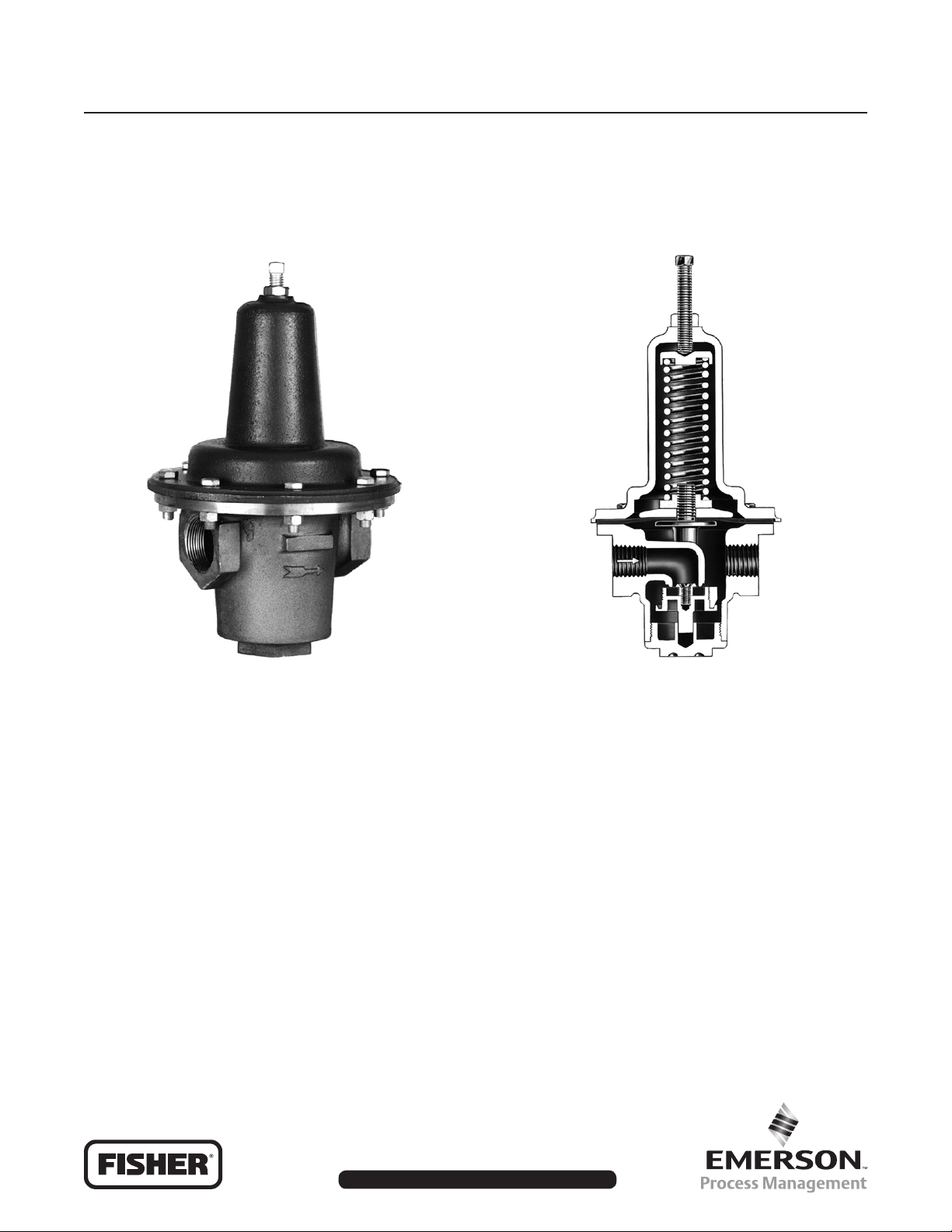
Figure 1. Type 75A Regulator
Introduction
The Type 75A regulator is designed to reduce
domestic or industrial water pressure, thus protecting
plumbing xtures and meters from high-pressure
surges. The Type 75A is self-contained, requiring no
external control line for operation.
Downstream pressure is directly registered under
the diaphragm. As the downstream pressure
increases, the diaphragm force overcomes the spring
W0057
SECTIONAL VIEW
FOR NPS 1/2, 3/4, 1, AND 1-1/2
(DN 15, 20, 25, AND 40) BODIES
compression, causes the valve disk to rise, and
reduces ow through the regulator.
If the downstream pressure decreases, the spring force
pushes the valve yoke and disk down to open the body
port. This permits increased ow and increases outlet
pressure to the desired level. The spring for each
regulator allows operation over an outlet pressure range
of 20 to 80 psig (1,4 to 5,5 bar). The outlet pressure
setting is easily changed by turning the adjusting screw.
D100116X012
www.emersonprocess.com/regulators
Page 2
Bulletin 71.1:75A
Specications
Body Size
NPS 1/2, 3/4, 1, and 1-1/2 (DN 15, 20, 25, and 40)
with integral cast seats
NPS 2 and 2-1/2 (DN 50 and 65) with
threaded-in seats
Maximum Inlet Pressure
(1)
200 psig (13,8 bar)
Outlet Pressure Ranges
20 to 80 psig (1,4 to 5,5 bar)
Maximum Allowable Outlet Pressure
(1)
10% above spring setting, or 5 psig (0,34 bar)
Minimum Operating Differential
5 psi (0,34 bar)
Maximum Operating Temperature
-20° to 150°F (-29° to 66°C)
Construction Materials
Body: Bronze
Spring Case: Cast iron
Threaded-in Orice (NPS 2 and 2-1/2
(DN 50 and 65) units only): Bronze
Valve Disk and Holder: Nitrile (NBR) and bronze
Diaphragm: Nitrile (NBR)
(1)
(1)
above setting, whichever is greater
1. The pressure/temperature limits in this bulletin or any applicable standard limitation should not be exceeded.
Table 1. Capacity Chart for Type 75A Regulator
CAPACITIES IN GPM (l/min) OF WATER
BODY SIZE, NPS (DN)
5 (0,34) 7 (0,48)
1/2 (15)
3/4 (20)
1 (25)
1-1/2 (40)
2 (50)
2-1/2 (65)
1. The 7 psig (0,48 bar) offset pressure and the related capacities are considered the upper limits of ows consistent with good piping practices and maximum uid velocities of
10 feet per second (3,05 m/s).
8 (30,3)
16 (60,6)
25 (94,6)
50 (189)
75 (284)
115 (435)
10 (37,9)
20 (75,7)
33 (125)
65 (246)
95 (360)
140 (530)
Droop, PSIG (bar)
(1)
10 (0,69) 15 (1,0)
14 (53,0)
28 (106)
45 (170)
85 (322)
125 (473)
185 (700)
19 (71,9)
40 (151)
60 (227)
115 (435)
175 (662)
260 (984)
WIDE-OPEN CV FOR
RELIEF SIZING
4.3
8.4
13.5
28.0
39.0
64.0
2
Page 3
Bulletin 71.1:75A
(+ 0,34)
+ 5
(0)
0
(- 0,34)
- 5
(-0,48)
- 7
(-0,69)
- 10
TO 320
(-1,0)
- 15
OFFSET, PSIG (bar)
(-1,4)
- 20
0 20 40 60 80 100 120 140 160 180 200 220 240 260
(0) (75,7) (151) (227) (303) (379) (454) (530) (606) (681) (757) (833) (908) (984)
NPS 1/2
(DN 15)
NPS 3/4
(DN 20)
NPS 1
(DN 25)
NPS 1-1/2
(DN 40)
NPS 2
(DN 50)
AT -20
NPS 2-1/2
(DN 65)
WATER FLOW, GPM (l/m)
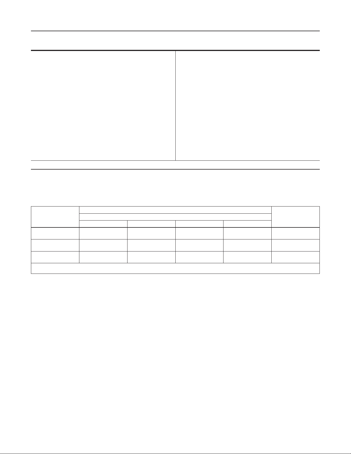
Figure 2. Type 75A Sizing Curves
Overpressure Protection
As is the case with most regulators, Type 75A has
maximum inlet pressure ratings which exceed the
outlet pressure ratings. Overpressuring any regulating
equipment may be hazardous. If actual inlet pressure
can exceed the outlet pressure ratings, some type of
overpressure protection is needed.
Sizing Information
Flow capacity and the maximum permissible offset
pressure that the system can tolerate determine the
correct regulator size for your application. Consult the
Type 75A Sizing Curves (Figure 2) and the Capacity
Chart (Table 1) to size the regulator. Several choices
may provide the required ow rate.
For example, if desired water ow is 30 GPM
(114 l/m), the rst intersecting curve (Figure 2) is
that of the NPS 3/4 (DN 20) regulator. At that point,
offset is 11 psi (0,76 bar), which is outside the limits of
good piping practice. Moving upward again, the next
intersecting curve is that of the NPS 1 (DN 25) regulator.
Here, offset is 6 psi (0,41 bar). This rating is permissible
and the NPS 1 (DN 25) regulator is acceptable.
Ordering Information
In order to prevent delays in order processing, please
specify type numbers and regulator size clearly.
3
Page 4

Bulletin 71.1:75A
B
A
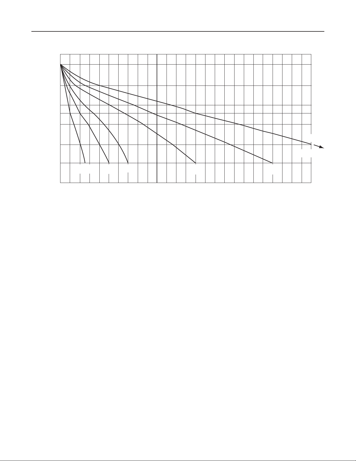
Figure 3. Dimensions
BODY SIZE,
NPS (DN)
1/2 (15)
3/4 (20)
1 (25)
1-1/2 (40)
2 (50)
2-1/2 (65)
E
D
C
A B C D E
9.75 (248)
11.25 (286)
12.25 (311)
13.62 (346)
18.62 (473)
19.12 (486)
DIMENSIONS, INCHES (mm)
7.12 (181)
8.38 (213)
9.12 (232)
9.88 (251)
13.88 (353)
14.12 (359)
4.31 (109)
5.44 (138)
6.62 (168)
8.19 (208)
9.38 (238)
9.38 (238)
3.75 (95)
4.25 (108)
4.75 (121)
5.88 (149)
6.38 (162)
7.75 (197)
1.88 (48)
2.12 (54)
2.38 (60)
2.94 (75)
3.19 (81)
3.88 (99)
Industrial Regulators
Emerson Process Management
Regulator Technologies, Inc.
USA - Headquarters
McKinney, Texas 75069-1872 USA
Tel: 1-800-558-5853
Outside U.S. 1-972-548-3574
Asia-Pacic
Shanghai, China 201206
Tel: +86 21 2892 9000
Europe
Bologna, Italy 40013
Tel: +39 051 4190611
Middle East and Africa
Dubai, United Arab Emirates
Natural Gas Technologies
Emerson Process Management
Regulator Technologies, Inc.
USA - Headquarters
McKinney, Texas 75069-1872 USA
Tel: 1-800-558-5853
Outside U.S. 1-972-548-3574
Asia-Pacic
Singapore, Singapore 128461
Tel: +65 6777 8211
Europe
Bologna, Italy 40013
Tel: +39 051 4190611
Gallardon, France 28320
Tel: +33 (0)2 37 33 47 00
TESCOM
Emerson Process Management
Tescom Corporation
USA - Headquarters
Elk River, Minnesota 55330-2445 USA
Tel: 1-763-241-3238
Europe
Selmsdorf, Germany 23923
Tel: +49 (0) 38823 31 0
Tel: +971 4811 8100
For further information visit www.emersonprocess.com/regulators
The Emerson logo is a trademark and service mark of Emerson Electric Co. All other marks are the property of their prospective owners. Fisher is a mark owned by Fisher Controls, Inc., a
business of Emerson Process Management.
The contents of this publication are presented for informational purposes only, and while every effort has been made to ensure their accuracy, they are not to be construed as warranties or
guarantees, express or implied, regarding the products or services described herein or their use or applicability. We reserve the right to modify or improve the designs or specications of such
products at any time without notice.
Emerson Process Management does not assume responsibility for the selection, use or maintenance of any product. Responsibility for proper selection, use and maintenance of any Emerson
Process Management product remains solely with the purchaser.
©Emerson Process Management Regulator Technologies, Inc., 1990; 2009 All Rights Reserved
 Loading...