

Page 1
Bulletin 71.1:67C
67C Series Instrument Supply Regulators
✰✰
✰ Designed for Digital Instrumentation
✰✰
✰✰
✰
Optional Smart Bleed™ Construction
✰✰
✰✰
✰ Optional Stainless Steel Construction
✰✰
✰✰
✰ Compact and Light Weight
✰✰
✰✰
✰ No Air Loss
✰✰
✰✰
✰ Easy Maintenance
✰✰
✰✰
✰ Optional Integral Filter
✰✰
W7412
March 2004
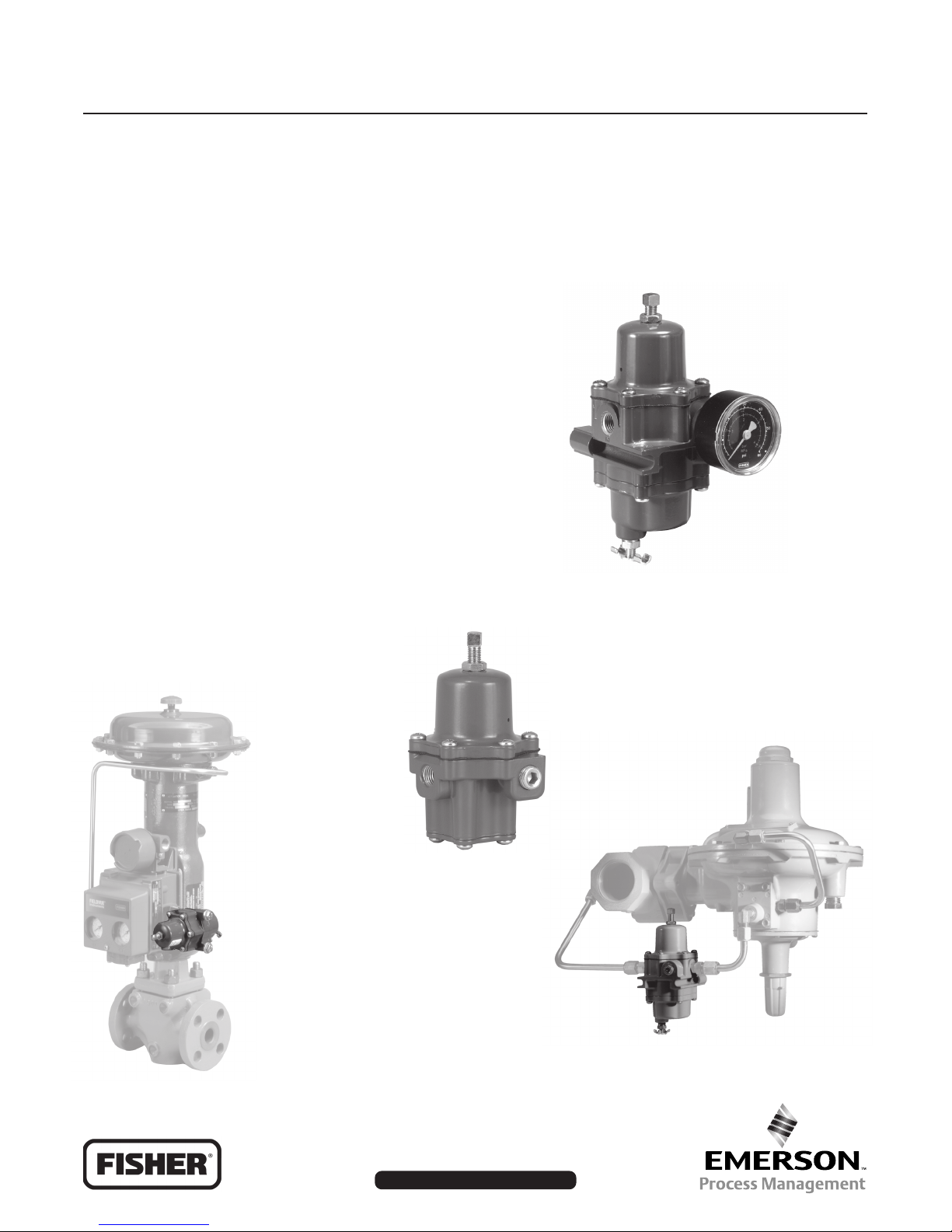
A 67CF Series filter
regulator shown with
optional pressure gauge
✰✰
✰ Optional Internal Relief Valve
✰✰
✰✰
✰ Rugged Construction
✰✰
W8438
A 67CF Series regulator used
as a supply regulator for
digital instrumentation
A 67C Series instrument
supply regulator
A 67CF Series regulator used as
a pilot supply regulator for the
Type 299H pressure regulator
W7426
W7423_1
D102656X012
www.FISHERregulators.com
Page 2

Bulletin 71.1:67C
Introduction
The 67C Series regulators are typically used to provide constantly controlled, reduced pressures to pneumatic and
electropneumatic controllers and other instruments. These direct-operated regulators are suitable for most air or
gas applications. Other applications include providing reduced pressures to air chucks, air jets, and spray guns.
Features
• Compact—The 67C Series regulators are engineered for outstanding performance in a compact,
light-weight package.
• Panel Mounting—Panel mount construction
includes spring case with 1/4-inch NPT vent,
handwheel adjusting screw, and mounting nut.
• Instrument Supply Regulator—The Types 67CF,
67CFR, 67CFS, and 67CFSR provide a clean air
supply to a variety of pneumatic and electro-pneumatic
instrumentation.
• Digital Instrument Supply Regulator—Designed
for the accuracy, repeatability, and hysteresis demands of digital instrumentation.
• Pilot Supply Regulator—Improves the accuracy
of two-path control regulators by reducing inlet sensitivity caused by fluctuating inlet pressures.
• Pressure Loading Regulator—Provides accuracy
and improved performance in dirty steam service by
eliminating the need for a pilot regulator (see figure 3).
• Sour Gas Service Capability—NACE MR0175 and
MR0103 compliant construction available.
• Optional Stainless Steel Construction—The
Types 67CS, 67CSR, 67CFS and 67CFSR provide high
resistance to corrosion especially beneficial in offshore
applications.
• Full Usable Capacity—Fisher regulators are
laboratory tested. 100 percent of the published
capacities can be used with confidence.
• Internal Relief—The Types 67CR, 67CSR, 67CFR,
and 67CFSR have an internal relief valve with a soft
seat for reliable shutoff with no discernible leakage.
These regulators are recommended for conserving
plant air.
• Smart Bleed™—Opens to exhaust downstream
pressure when inlet pressure drops below outlet
pressure. Recommended for deadend service.
• Integral Filter—The Types 67CF, 67CFR, 67CFS,
and 67CFSR have an integral filter ensuring clean
downstream air supply.
• Ease of Maintenance—No special tools are
required to perform maintenance, and all maintenance
can be performed with the regulator in the line. Filter
elements are easily replaced. The one-piece valve
plug cartridge allows easy inspection and replacement.
• Rugged Construction—The 67C Series regulators
are engineered for longer service life with minimal
maintenance requirements.
• Second Outlet—Body side outlet for pressure
gauge or other uses.
• Powder Paint Coating—Types 67C, 67CR, 67CF,
and 67CFR are powder paint coated, offering impact,
abrasion, and corrosion resistance. Stainless steel
regulators (Types 67CS, 67CSR, 67CFS and 67CFSR)
are not painted.
• Corrosion Resistant Fasteners—Bolting and
adjusting screw are double zinc-chromated for enhanced corrosion resistance. Optional stainless steel
bolting and adjusting screw are also available.
Table 1. Outlet Pressure Ranges and Control Spring Data
epyT
,RC76,C76
RFC76,FC76
,RSC76,SC76
RSFC76,SFC76
2
)rab(GISP
02ot0
53ot0
06ot0
521ot0
53ot0
0
6ot0
521ot0
02ot0
53ot0
06ot0
521ot0
051ot0
)4,1ot0(
)4,2ot0(
)1,4ot0(
)6,8ot0(
)4,2ot0(
)1,4ot0(
)6,8ot0(
)4,1ot0(
)4,2ot0(
)1,4ot0(
)6
,8ot0(
,SEGNARERUSSERPTELTUO
roloClairetaMrebmuNtraP)mm(hcnI,retemaiDeriW
epirtsneerg
revlis
epirtseulb
epirtsder
epirtsrevlis
eulb
der
neerg
epirtsrevlis
eulb
)3,01ot0(
der
kcalb
iWcisuM
er
lenocnI
lenocnI
ATADGNIRPSLORTNOC
210T90870EG
2100T95041T
2100T85041T
2100T06041T
2100T31141T
2100T41141T
2100T51141T
210X9271C01
2100T31141T
2100T41141T
2100T51141T
210X03
71C01
531.0
)34,3(
651.0
)69,3(
071.0
)23,4(
702.0
)62,5(
651.0
)69,3(
271.0
)73,4(
702.0
)62,5(
531.0
)34,3(
651.0
)69,3(
271.0
)73,4(
702.0
)62,5(
052.0
)53,6(
Page 3

Specifications
Bulletin 71.1:67C
Body Size, Inlet and Outlets Connection Style
1/4-inch NPT
Construction Materials
See Table 2
Maximum Inlet Pressure (Body Rating)
(1)
All except 67CS and 67CSR: 250 psig (17,2 bar)
Type 67CS and 67CSR: 400 psig (27,6 bar)
Outlet Pressure Ranges
See Table 1
Maximum Emergency Outlet Pressure
(1)
50 psi (3,4 bar) over outlet pressure setting
Capacities
See Table 3 and Capacity Information section
Wide-Open Flow Coefficients
Main Valve:
Internal Relief Valve:
Cg:
11.7;
Cv:
Cg:
0.36;
1.45;
C1:
Cv:
32.2;
0.045;
C1:
IEC Sizing Cooefficients
Main Valve:
XT:
0.66;
FL:
0.89;
FD:
0.50
Accuracy
Inlet Sensitivity: Less than 0.2 psig (0,014 bar)
change in outlet pressure for every 25 psig
(1,72 bar) change in inlet pressure
Repeatability: 0.1 psig (0,0069 bar)
(2)
Air Consumption: testing repeatedly shows
no discernible leakage
Type 67CR, 67CSR, 67CFR, and 67CFSR Internal
Relief Performance
Low capacity for minor seat leakage only; other
overpressure protection must be provided if inlet
pressure can exceed the maximum pressure rating
of downstream equipment or exceeds maximum
outlet pressure rating of the regulator.
Approximate Unit Weight
Types 67C, 67CR, 67CF, and 67CFR:
1 pound (0,5 kg)
Types 67CS and 67CSR:
2.5 pounds (1,2 kg)
Types 67CFS and 67CFSR:
4 pounds (1,8 kg)
32.8
Smart Bleed™ Check Valve Setpoint
6 psi (0,4 bar) differential
Pressure Registration
Internal
Drain Valve and Spring Case Vent Location
Aligned with inlet standard, other positions optional
Regulator Temperature Capabilities
With Nitrile (NBR)
Standard Bolting:
Stainless Steel Bolting:
-20 to 180°F (-29 to 82°C)
-40 to 180°F (-40 to 82°C)
With Fluoroelastomer (FKM):
0 to 300°F (-18 to 149°C)
With Silicone (VMQ)
(3)
Diaphragm and Low
Temperature bolting: -60 to 180°F (-51 to 82°C)
With Gauges: -20 to 180°F (-29 to 82°C)
Type 67CF, 67CFR, 67CFS, and 67CFSR Filter
Capabilities
Free Area: 12 times pipe area
Micron Rating:
Glass Fiber Element:
Stainless Steel Element:
Cellulose Element:
5 microns
40 microns
40 microns
Options
All Types
• Handwheel adjusting screw
• Inlet screen
• NACE MR0175
(4)
or NACE MR0103 construction
• Panel mount (includes spring case with 1/4-inch
vent, handwheel, and panel mounting nut)
• Closing cap (available on spring case with
1/4-inch NPT vent)
• Fluoroelastomer (FKM) elastomers for high
temperatures and/or corrosive chemicals
• Silicone (VMQ) elastomers for cold temperatures
• Fixed Bleed Restriction
• Triple scale outlet pressure gauge (brass or
stainless steel)
• Stainless steel stem on the valve plug
• Tire valve or pipe plug in second outlet
Type 67CFR only
• Smart Bleed™ internal check valve
Types 67CF and 67CFR only
• Stainless steel drain valve
1. The pressure/temperature limits in this bulletin and any applicable standard or code limitation should not be exceeded.
2. Repeatability is the measure of the regulator's ability to return to setpoint consistently when traveling from steady state to transient to steady state.
3. Silicone is not compatible with hydrocarbon gas.
4. Product complies with the material requirements of NACE MR0175. Environmental limits may apply.
3
Page 4
Bulletin 71.1:67C
TYPE 67CR OR 67CSR
TYPE 67C OR 67CS
INLET PRESSURE
OUTLET PRESSURE
ATMOSPHERIC PRESSURE
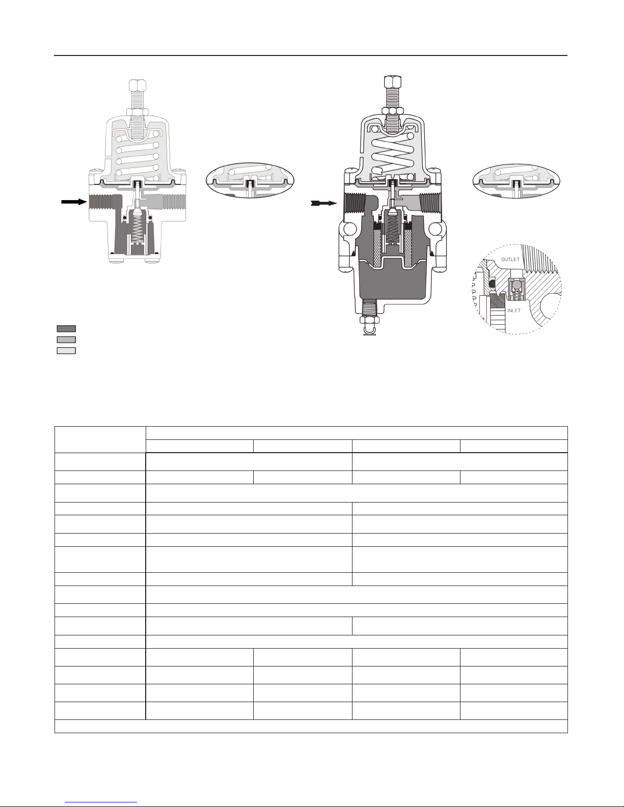
Figure 2. 67C Series Operational Schematics
Table 2. 67C Series Construction Materials
LAIRETAM
dnaydoB
esaCgnirpS
etalPmottoB
evlaVdnatsoPrehsuP
egdirtraC
taeSgnirpSreppU
,taeSgnirpSrewoL
etalPmgarhpaiD
gnirpSlortnoC
gulPevlaV
gnirpSevlaV
mgarhpaiD
sgniR-Odna
steksaGdnataeStfoS
gnitsujdA,gnitloB
tunkcoL,wercS
leehwdnaH
reniateRretliF
tnemelEretliF
aVniarD
evl
llewpirD
RC76dnaC76RFC76dnaFC76RSC76dnaSC76RSFC76dnaSFC76
tssselniatS
atS lenocnI
niZ leetssselniatS613
---leetSdetalP---
---
---
---
TYPE 67CF OR 67CFS
W7433
TYPE 67CFR OR 67CFSR
SMART BLEED™ OPTION
TYPE 67CFR ONLY
EPYT
)083yollA/58BMTSA(munimulA l
leetssselniatS613---leetSsselniatS613---
rretseyloP
nise
leetSdetalp-cniZ leetssselniatS613
cnoisrevnocetamorhC leetssselniatS613
iNhtiwmetsssarB
munimuladetao
)ECAN(lenocnIroleetSdetalP lenocnI
,gulpelirt
)ECAN(lenocnIroleetssselni
leetssselniatSroleetsdetalp-c
8BMTSA(
.)RSFC76,RFC76,RSC76,RC76(feilerlanretnihtiwelbaliavaylnomgarhpaidenociliS.1
ro,gulpremotsaleoroulFroelirtiNhtiwmetsmunimulA
gulpremotsaleoroulFroelirtiNhtiwmetslee
)1(
enociliSro,remotsaleoroulF,elirtiN
remotsaleoroulFroelirtiN
leehwdnahniserhtiwwercsleetsdetalp-cniZ
,esolulleC
rossarB
munimulA
leetssselniatSro,rebifssalG
leetssselniatS
)083yollA/5
---
---
---leetssselniatSM3FC/M8FC
eetssselniatSM3FC/M8FC
htiwmetsleetssselniatS613
gulpremotsaleoroulFroelirtiN
613
eetssselniatS
l
rorebifssalG
leetssselniatS613
roleetSsselniatS613
leetssselniatS8-81
4
Page 5

Bulletin 71.1:67C
Principle of Operation (figure 2)
Downstream pressure is registered internally on the
lower side of the diaphragm. When the downstream
pressure is at or above the set pressure, the valve plug
is held against the orifice and there is no flow through
the regulator. When demand increases, downstream
pressure drops slightly allowing the spring to extend,
moving the stem down and the valve plug away from
the orifice. This allows flow through the regulator.
Internal Relief (Types 67CR, 67CSR,
67CFR, and 67CFSR)
If for some reason, outside of normal operating
conditions, the downstream pressure exceeds the set
point of the regulator, the force created by the
downstream pressure will lift the diaphragm until the
diaphragm is lifted off the relief seat. This allows flow
through the token relief. The relief valve on the
Type 67CR, 67CSR, 67CFR, or 67CFSR is an elastomer
plug that prevents leakage of air from the downstream
to atmosphere during normal operation, thereby
conserving plant air.
Smart Bleed™ Airset
In some cases, it is desired to exhaust downstream
pressure if inlet pressure is lost or drops below the
setpoint of the regulator. For example, if the regulator is
installed on equipment that at times has no flow
demand but is expected to backflow on loss of inlet
pressure. The Type 67CFR can be ordered with the
Smart Bleed™ option which includes an internal check
valve for this application. During operation, if inlet
pressure is lost, or decreases below the setpoint of the
regulator, the downstream pressure will back flow
upstream through the regulator and check valve. This
option eliminates the need for a fixed bleed downstream
of the regulator, thereby conserving plant air.
Overpressure Protection
The 67C Series regulators have maximum outlet
pressure ratings that are lower than their maximum
inlet pressure ratings. A pressure relieving or pressure
limiting device is needed if inlet pressure can exceed
the maximum outlet pressure rating. Refer to the
Capacity Information section and the Wide-Open
Coefficients for Relief Valve Sizing in the Specifications on page 3 to determine the required relief valve
capacity.
leakage only. Other overpressure protection must be
provided if the maximum inlet pressure can exceed the
maximum pressure rating of the downstream equipment
or exceeds maximum outlet pressure rating of the
Type 67CR, 67CSR, 67CFR, or 67CFSR regulator.
Capacity Information
Table 3 shows the air regulating capacities of the
67C Series regulators at selected inlet pressures and
outlet pressure settings. Flows are shown in scfh
(at 60°F and 14.7 psia) and in m³/h(n) (at 0°C and
1,01325 bar) of air.
Note
The 67C Series regulators may be sized
for 100% flow using capacities as shown
in table 3. It is not necessary to reduce
published capacities.
To determine the equivalent capacities for other gases,
multiply the table capacity by the following appropriate
conversion factor: 1.29 for 0.6 specific gravity natural
gas, 0.810 for propane, 0.707 for butane, or 1.018 for
nitrogen. For gases of other specific gravities, divide
the table capacities by the square root of the appropriate specific gravity. To find wide-open flow capacities
for relief sizing at any inlet pressure, perform one of
the following procedures. Then, if necessary, convert
using the factors provided above.
For critical pressure drops (absolute outlet pressure
equal to or less than one-half of absolute inlet pressure), use the following formula:
Q = (P1)(Cg)
For pressure drops lower than critical (absolute
outlet pressure greater than one-half of absolute inlet
pressure), use the following formula:
520
Q
where,
Q = gas flow rate, scfh
P1= absolute inlet pressure, psia (P1 gauge + 14.7)
Cg= gas sizing coefficient
G = specific gravity of the gas
T = absolute temperature of gas at inlet, °Rankine
= flow coefficient (Cg ÷ Cv)
C
1
∆P = pressure drop across the regulator, psi
CPSIN
g1=
GT
⎛
3417
⎜
⎜
⎝
11C
⎞
∆
P
⎟
DEG
⎟
P
⎠
Type 67CR, 67CSR, 67CFR, and 67CFSR regulators
have a low capacity internal relief valve for minor seat
Then, if capacity is desired in normal cubic meters per
hour (at 0°C and 1,01325 bar), multiply scfh by 0.0268.
5
Page 6

Bulletin 71.1:67C
Table 3. Capacities
GISPrab()
ot0(53ot0
041T
ERUSSERPTELTUO=
TRAPGNIRPS,EGNAR
,ROLOCDNAREBMUN
)4,2
)revliS(2100T95041T
2100T31141T
)epirtSrevliS(
)1,4ot0(06ot0
2100T85041T
)epirtseulB(
)eulB(2100T41141T
)6,8ot0(521ot0
2100T06
)epirtsdeR(
)deR(2100T51141T
)1(
)6,8ot0(051ot0
)kcalB(210X0371C01
TELTUO
,ERUSSERP
(GISPrab)
51)0,1(
02)4,1(
53)4,2(
53)4,2(
06)1,4(
08)5,5(
521)6,8(
08)5,5(
531)3,9(
051)3,01(
,ERUSSERPTELNI
(GISPrab)
05
)4,3(
57
)2,5(
001
)9,6(
051
)3,01(
052
)2,71
(
004
05
001
051
052
004
05
001
051
052
004
05
001
051
052
004
001
051
052
004
001
051
052
004
051
052
004
052
004
052
004
052
004
ylnoRSFC76dnaSFC76,RSC76,SC76sepyTrofelbaliavA.1
mixamahtiw)rab2,71(gisp052evobaserusserptelnI.2
)2(
)6,72(
)4,3(
57
)2,5(
)9,6(
)3,01(
)2,71(
)2(
)6,72(
)4,3(
57
)2,5(
)9,6(
)3,01(
)2,71(
)2(
)6,72(
)4,3(
57
)2,5(
)9,6(
)3,01(
)2,71(
)2(
)6,72(
57
)2,5(
)9,6(
)3,01(
)2,71(
)2(
)6,72(
)9,6(
)3,01(
)2,71(
)2(
)6,72(
)3,01(
)2,71(
)2(
)6,72(
)2,71(
)2(
)6,72(
)2,71(
)2(
)6,72(
)2,71(
)2(
)6,72(
poorD%01poorD%02poorD%01poorD%02
052
)07,6(
043
)11,9(
034
)5,11(
086
)2,81(
0031
)8,43(
093
)5,01(
013
)13,8(
024
)3,11(
026
)6,61(
069
)7,52(
0551
)5,14(
0021
)2,23(
093
)5,01(
095
)8,51(
077
)6,02(
0021
)2,23(
0022
)9,85(
0582
)4,67(
013
)13,8(
044
)8,11(
065
)0,51(
087
)9,02(
0541
)9,83(
077
)6,02(
025
)9,31(
057
)1,02(
0011
)5,92(
0502
)9,45(
0023
)8,58(
005
)4,31(
057
)1,02(
0021
)2,23(
019
)4,42(
009
)1,42(
0651
)8,14(
0022
)0,95(
055
)7,41(
004
)7,01(
079
)0,62(
048
)5,22(
0011
)5,92(
049
)2,52(
NISEITICAPACm
RSC76dna,SC76,RC76,C76sepyT RSFC76dna,SFC76,RFC76,FC76sepyT
034
)5,11(
016
)3,61(
008
)4,12(
0021
)2,23(
0091
)
9,05(
0581
)0,05(
064
)3,21(
007
)8,81(
049
)2,52(
0541
)9,83(
)6,75(
0512
)7,37(
0572
094
)1,31(
058
)8,22(
0511
)8,03(
4(
0571
)9,6
)3,27(
0072
)5,29(
0543
044
)8,11(
076
)0,81(
009
)1,42(
0531
)2,63(
0,95(
0022
)
)0,76(
0052
027
)3,91(
0501
)1,82(
0071
)6,54(
0582
)4,67(
0034
)511(
008
)4,12(
0021
)2,23(
0502
)9,45(
0073
)2,99(
0521
)5,33(
0542
)6,56(
0534
)711(
0021
)2,23(
0011
)5,92(
0081
)2,84(
0532
)0,36(
0581
)6,94(
0052
)0,76(
.RSC76dnaSC76sepyTnoelbaliavaylno)rab6,72(gisp004fomu
))n(h/RIAFO
052
)07,6(
003
)40,8(
033
)48,8(
004
)7,01(
054
)1,21(
--
--
053
)83,9(
035
)2,41(
057
)1,02(
0041
)5,73(
0552
)3,86(
--
--
093
)5,01(
046
)1,71(
048
)5,22(
0541
)9,83(
0542
)6,56(
--
--
033
)48,8(
005
)4,31(
007
)8,81(
0501
)1,82(
0002
)6,35(
--
--
025
)9,31(
07
7
)6,02(
0011
)5,92(
0542
)6,56(
--
--
035
)2,41(
087
)9,02(
0521
)
5,33(
--
--
009
)1,42(
0561
)2,44(
--
--
055
)7,41(
--
--
0011
)5,92(
--
--
0011
)5,92(
--
--
034
)5,11(
096
)5,81(
0001
)8,62(
0061
)9,
24(
0081
)2,84(
--
--
005
)4,31(
028
)0,22(
0011
)5,92(
0061
)9,24(
0072
)3,27(
--
--
005
)4,31(
028
)0,22(
0011
)5,9
2(
0561
)2,44(
0072
)3,27(
--
--
074
)6,21(
037
)6,91(
0001
)8,62(
0551
)
5,14(
0062
)7,96(
--
--
027
)3,91(
0001
)8,62(
0061
)9,24(
0572
)7,37(
--
--
087
)9,02(
0021
)2,23(
0022
)9,85(
--
--
0511
)8,03(
6(
0542
)6,5
--
--
0021
)2,23(
--
--
0081
)2,84(
--
--
0581
)6,94(
--
--
3
(HFCS
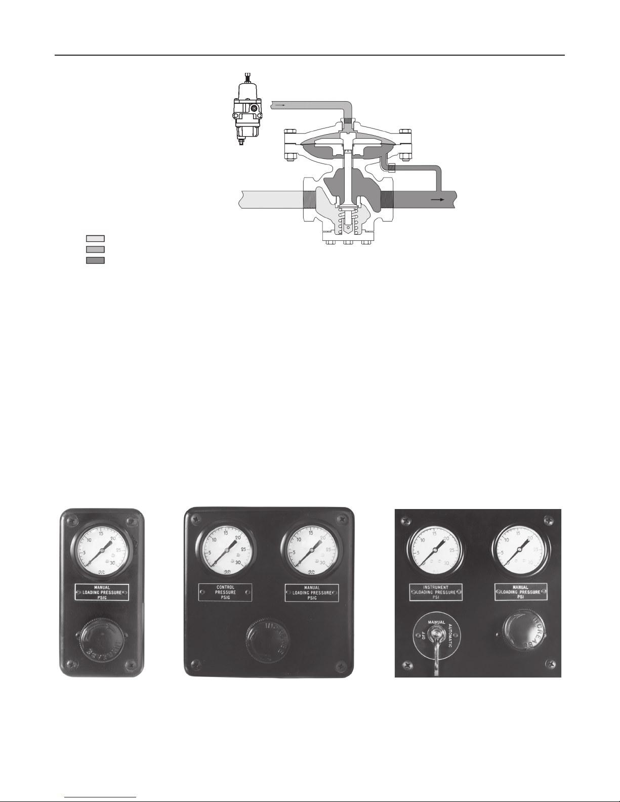
670 Series Panel-Mounted Loading
Regulators (figure 4)
The 670 Series panel-mounted loading regulators are
compact, rugged units used primarily for manually
loading pressure-balanced gas regulators and providing
manual control for diaphragm actuator control valves.
Applications include remote control of gas pressure to
burners in refineries, power plants, and various
process furnaces.
Three basic panels are available within the product
line, each having one 67C Series pressure regulator
6
connected to one or two gauges and a changeover
valve. A single gauge typically shows loading
pressure to the control valve. For more information
see bulletin 62.3:670.
Ordering Information
When ordering, complete the Ordering Guide on page
12. Refer to the Specifications on page 3. Review the
description to the right of each specification and the
information in each referenced table or figure. Specify
your choice whenever a selection is offered.
Page 7
67C SERIES
FILTER REGULATOR
UPSTREAM PRESSURE
LOADING PRESSURE
DOWNSTREAM PRESSURE
A 67C SERIES PRESSURE LOADING REGULATOR USED WITH THE TYPE 92P STEAM REGULATOR ELIMINATES THE NEED FOR A
PILOT REGULATOR. THIS PROVIDES HIGH ACCURACY AND IMPROVED PERFORMANCE IN DIRTY STEAM SERVICE.
W7434
TYPE 92P
STEAM REGULATOR
Figure 3. 67C Series Regulator Used to Pressure Load a 92P Steam Regulator
Bulletin 71.1:67C
1-GAUGE PANEL 2-GAUGE PANEL 2-GAUGE PANEL WITH
Figure 4. 670 Series Typical Panel Layouts
CHANGEOVER VALVE
7
Page 8
Bulletin 71.1:67C
A
MAX
B
4.56
(116)
2.92
(74)
1.46
(37)
STANDARD DIMENSIONS
FOR GAUGE OPTION
2.92
(74)
4.56
(116)
1.46
(37)
SIDE OUTLET
1/4-INCH NPT
OPTIONAL GAUGE
INLET CONNECTION
1/4-INCH NPT
INCHES
(mm)
2.56
(65)
0.50
(13)
STANDARD DIMENSIONS
2.56
(65)
1.43
(36)
OUTLET
CONNECTIONS
1/4-INCH NPT
CLOSING CAP
2.37
(60)
PANEL
MAX
0.12 TO 0.25
(3,0 TO 6,5)
A
MAX
D
C
SIDE OUTLET TAPPED
1/4-INCH NPT
DIMENSIONS FOR PANEL MOUNT OPTION WITH
HAND WHEEL AND 1/4-INCH SPRING CASE VENT
EPYT
SNOISNEMIDDRADNATS
ABAACD
RC76,C76)98(05.3)8
3(15.1)711(06.4)911(96.4)72(80.1)95(33.2
RSC76,SC76)501(31.4)14(26.1)521(39.4)721(00.5)92(41.1)76(56.2
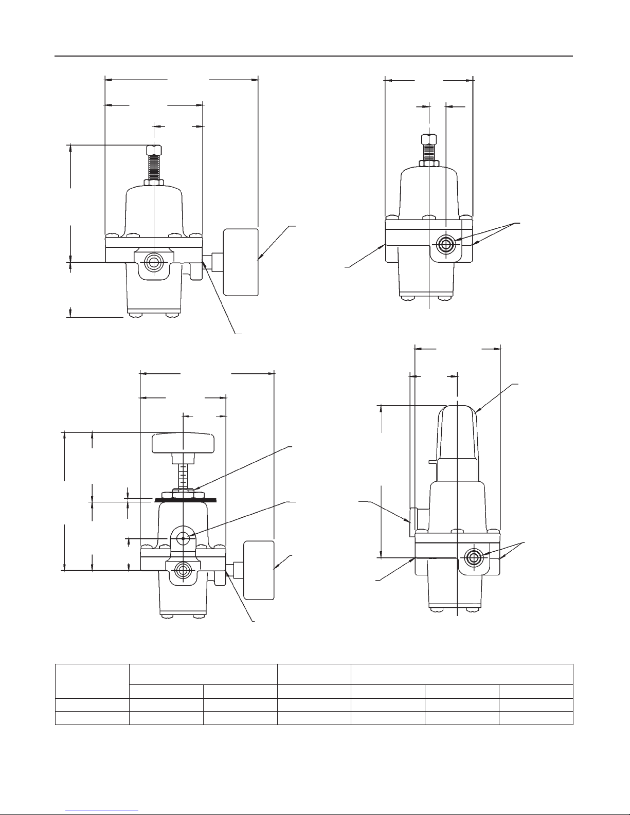
Figure 5. Types 67C, 67CR, 67CS, and 67CSR Dimensions
0.72-INCH (1,8 mm)
SPRING CASE
PANEL BOSS
1/4-INCH NPT VENT
OPTIONAL GAUGE
INLET CONNECTION
1/4-INCH NPT
HTIWNOISNEMID
PACGNISOLC
A
DIMENSIONS WITH CLOSING CAP
AND 1/4-INCH SPRING CASE VENT
OUTLET
CONNECTIONS
1/4-INCH NPT
SNOISNEMIDLEEHWDNAHHTIWNOITPOTNUOMLENAP
8
Page 9
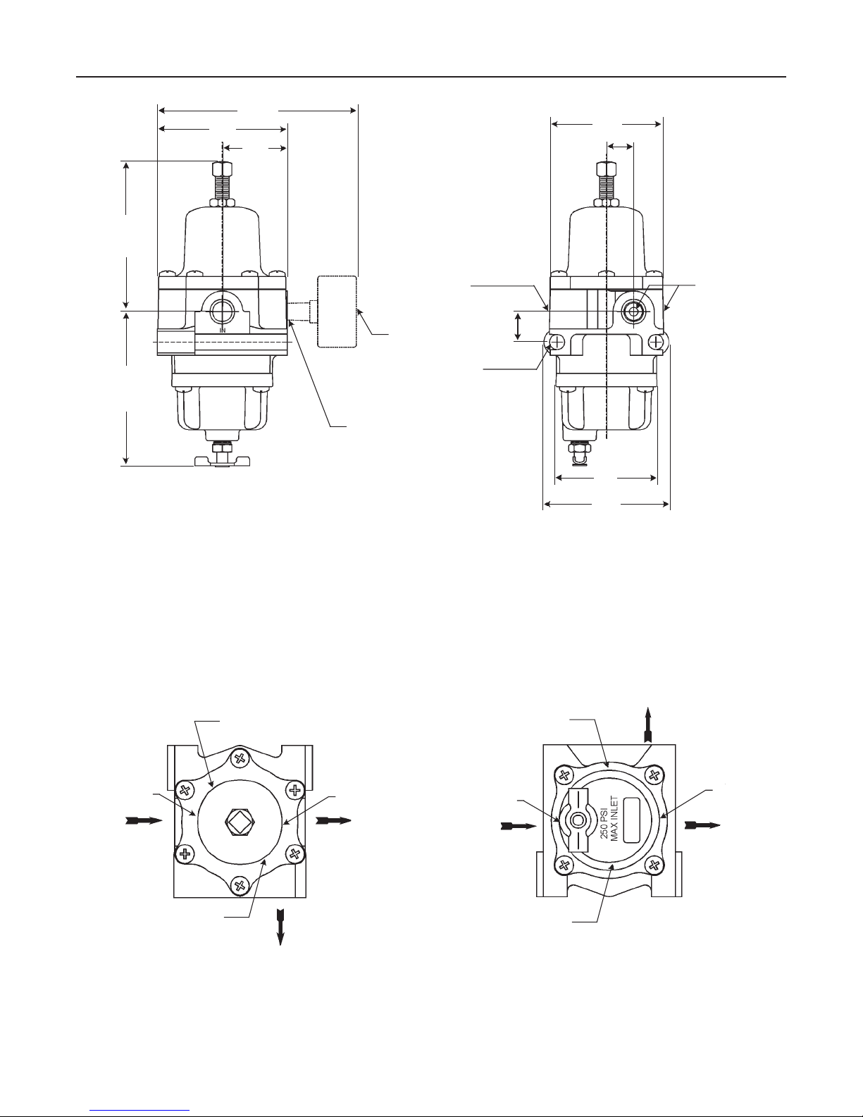
3.50
(89)
3.00
(76)
4.56
(116)
1.48
(38)
Bulletin 71.1:67C
2.56
(65)
0.62
(16)
3.50
(89)
B2699_A
DIMENSIONS
FOR GAUGE OPTION
Figure 6. Types 67CF and 67CFR Dimensions
INLET CONNECTION
1/4-INCH NPT
OPTIONAL GAUGE
SIDE OUTLET
1/4-INCH NPT
MOUNTING HOLES
FOR 5/16-INCH
DIAMETER BOLTS
INCHES
(mm)
0.69
(18)
B2699_B
2.25
(57)
2.87
(73)
STANDARD DIMENSIONS
OUTLET
CONNECTIONS
1/4-INCH NPT
VENT POSITION 2
VENT POSITION 1
(STANDARD)
INLET
VENT POSITION 4
B2699_C
GAUGE
VENT POSITIONS
Figure 7. 67C Series Vent and Drain Valve Positions
VENT POSITION 3
OUTLET
DRAIN VALVE
POSITION 1
(STANDARD)
B2699_D
DRAIN VALVE
POSITION 4
INLET OUTLET
DRAIN VALVE
POSITION 2
GAUGE
DRAIN VALVE POSITIONS
DRAIN VALVE
POSITION 3
9
Page 10
Bulletin 71.1:67C
4.56
(116)
3.00
(76)
4.78
(121)
MAX
3.50
(89)
B2700_A
2.37
(60)
MAX
2.41
(61)
PANEL
0.12 TO 0.25
(3,0 TO 6,5)
1.14
(29)
1.48
(38)
DIMENSIONS FOR PANEL MOUNT OPTION
WITH HAND WHEEL AND 1/4-INCH SPRING CASE VENT
0.72-INCH (1,8 mm)
SPRING CASE
PANEL BOSS
1/4-INCH NPT VENT
INLET CONNECTION
1/4-INCH NPT
OPTIONAL GAUGE
MOUNTING HOLES
FOR 5/16-INCH
DIAMETER BOLTS
SIDE OUTLET TAPPED
1/4-INCH NPT
INCHES
(mm)
2.56
(65)
1.43
(36)
4.69
(119)
0.69
(18)
2.25
(57)
2.87
B2700_B
(73)
DIMENSIONS FOR CLOSING CAP OPTION
WITH 1/4-INCH SPRING CASE VENT
CLOSING CAP
OUTLET
CONNECTIONS
1/4-INCH NPT
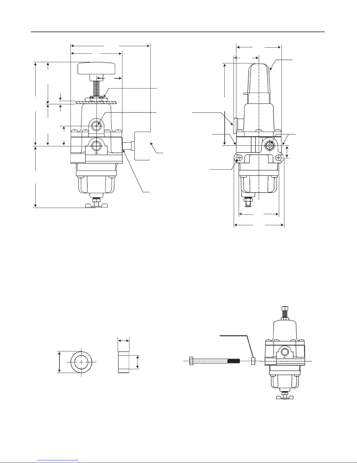
Figure 8. Types 67CF and 67CFR Dimensions (continued)
0.18
(4,57)
0.50
OD
(12.7)
B2697_B
SPACER OUTER DIAMETER SPACER WIDTH AND
INNER DIAMETER
0.32
(8.12)
ID
Figure 9. Spacer Dimensions and Installation Schematic
SPACER
(FOR INSTALLING A 67CF SERIES
REGULATOR IN AN EXISTING
INSTALLATION IF THE MOUNTING
BOLTS ARE TOO LONG)
B2697_A
10
Page 11
Bulletin 71.1:67C
4.93
(125)
4.00
(102)
1.14
(29)
3.00
(76)
4.56
(116)
1.48
(38)
OPTIONAL
GAUGE
1/4-INCH NPT
INLET CONNECTION
VENT 1/4 NPT
INCHES
(mm)
1/4-INCH NPT INLET
CONNECTION
MOUNTING HOLES
FOR 5/16-INCH
DIAMETER BOLTS
0.69
(18)
1.43
(36)
2.56
(65)
2.25
(57)
2.87
(73)
0.62
(16)
CLOSING
CAP
1/4-INCH NPT
OUTLET
CONNECTIONS
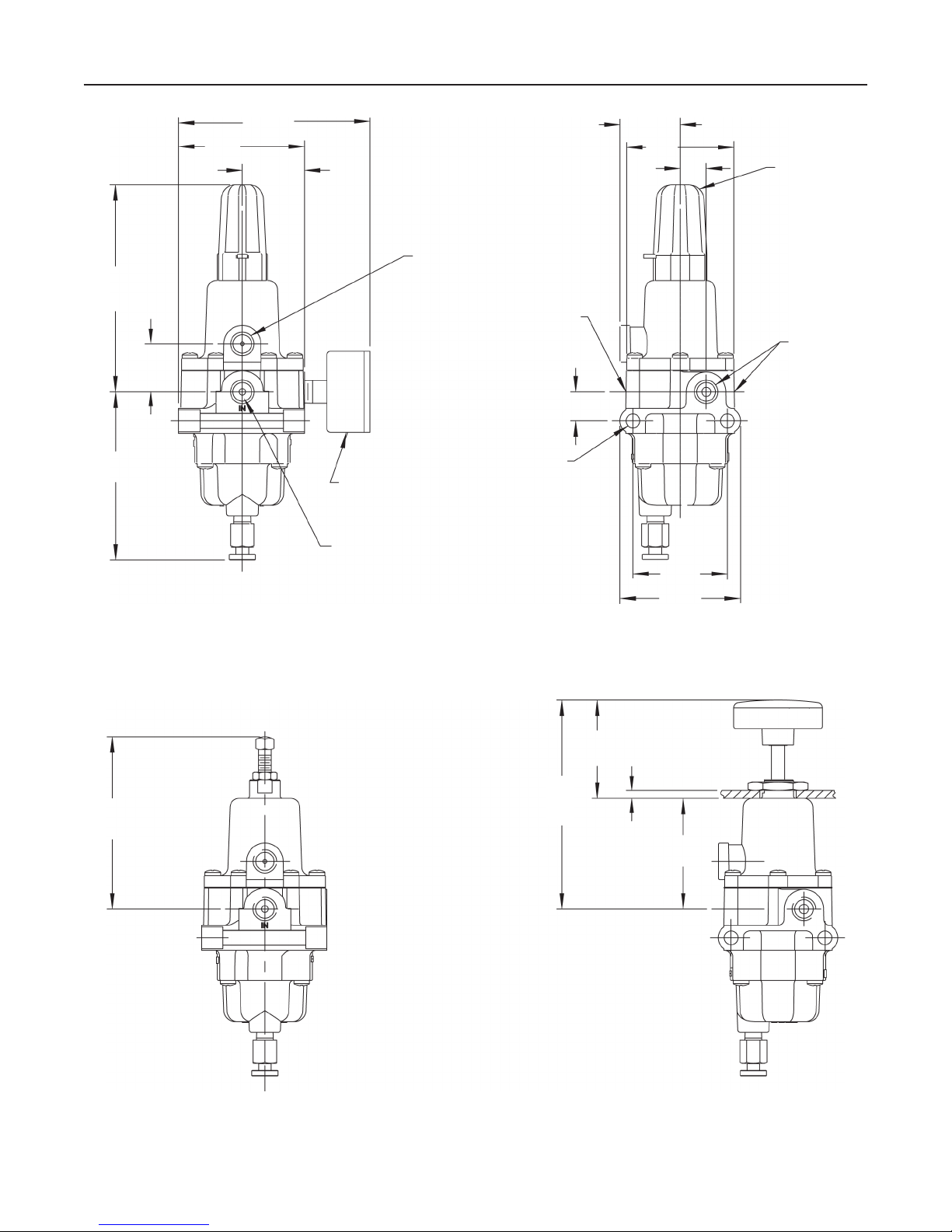
STANDARD DIMENSIONS (INCLUDING CLOSING CAP) STANDARD DIMENSIONS (INCLUDING CLOSING CAP)
2.37
(60)
MAX
5.00
4.13
(105)
MAXIMUM
INCHES
(mm)
(127)
MAXIMUM
PANEL
0.12-0.25
(3-6,5)
2.65
(67)
DIMENSIONS WITHOUT CLOSING CAP
Figure 10. Types 67CFS and 67CFSR Dimensions
DIMENSIONS FOR PANEL MOUNT OPTION WITH HANDWHEEL
11
Page 12

Bulletin 71.1:67C
Ordering Guide
Type (Select One)
Type 67C (aluminum without internal relief)***
Type 67CR (aluminum with internal relief)***
Type 67CS (stainless steel without internal relief)***
Type 67CSR (stainless steel with internal relief)***
Type 67CF (aluminum with filter and without internal relief)***
Type 67CFR (aluminum with filter and internal relief)***
Type 67CFS (stainless steel with filter and without
internal relief)***
Type 67CFSR (stainless steel with filter and internal relief)***
Quantity (Specify)
Spring Case Style (Select One)
Drilled hole vent (67C, 67CR, 67CF, 67CFR standard)***
1/4-inch NPT vent (67CS, 67CSR, 67CFS, 67CFSR standard)***
Single hole panel mount***
Adjusting Screw (Select One)
Square head (67C, 67CR, 67CF, 67CFR standard)***
Square head with closing cap (67CS, 67CSR, 67CFS,
67CFSR standard)***
Handwheel***
Outlet Pressure Range (Select One)
0 to 20 psig (0 to 1,4 bar)***
0 to 35 psig (0 to 2,4 bar)***
0 to 60 psig (0 to 4,1 bar)***
0 to 125 psig (0 to 8,6 bar)***
0 to 150 psig (0 to 10,3 bar) (67CS, 67CSR, 67CFS, 67CFSR
only)***
Diaphragm, O-Rings, and Valve Plug (Select One)
Nitrile (NBR) (standard)***
Fluoroelastomer (FKM)**
Silicone (VMQ) diaphragm, O-rings, and nitrile valve plug*
Filter Material (Select One)
Cellulose (40 microns)(67CF, 67CFR standard)***
Glass (5 microns)***
Stainless steel (40 microns)(67CFS, 67CFSR standard)***
Drain Valve (Select One)
Brass (67CF, 67CFR standard)***
Stainless steel (67CFS, 67CFSR standard)***
Drain Valve Location (Select One)
Position 1 - Aligned with inlet (standard)***
Position 2
Position 3
Position 4
ediuGredrOkciuQsrotalugeRrehsiF
***tnempihSrofelbaliavAylidaeR-dradnatS
**tnempihSrofemiTlanoitiddAwollA-
*
epS.straPdekcotS-noNmorfdetcurtsnoC,redrOlaic
stsegnolehthtiw
dradnatS-noN
tlusnoC.ytilibaliavArofevitatneserpeRselaSreh
siFruoY
.noitcurtsnocdetseuqerehtrofemitgnippih
tnenopmocehtybdenimretedsideredrogniebtcudorpehtfoytilibaliavA
Spring Case Vent Location (Select One)
Position 1 - Aligned with inlet (standard)***
Position 2
Position 3
Position 4
Fixed Bleed for Type 67CR, 67CSR, 67CFR, or 67CFSR (Optional)
Yes**
Smart Bleed™ Internal Check Valve Airset (Optional - 67CFR only)
Yes**
Second Outlet (Select One)
Open (67C, 67CR, 67CF, 67CFR standard)***
Plugged with pipe plug (67CS, 67CSR, 67CFS, 67CFSR
standard)***
Tire Valve***
Pressure Gauge (see below)
Triple Scale Pressure Gauge (Optional)
Brass Gauge or Stainless Steel Gauge
0 to 30 psig/0 to 0.2 MPa/0 to 2 bar***
0 to 60 psig/0 to 0.4 MPa/0 to 4 bar***
0 to 160 psig/0 to 1.1 MPa/0 to 11 bar***
NACE MR0175 Construction (Optional)
(1)
Yes (not available with gauge)**
1. Product complies with the material requirements of NACE MR0175.
Environmental limits may apply.
NACE MR0103 Construction (Optional)
Yes (not available with gauge)**
Replacement Parts Kit (Optional)
Yes, send one replacement parts kit to match this order.
Specification Worksheet
Application (Please designate units):
Specific Use
Line Size
Gas Type and Specific Gravity
Gas Temperature
Does the Application Require Overpressure Protection?
No Yes, if so, which is preferred:
Relief Valve Monitor Regulator Shutoff Device
Is overpressure protection equipment selection assistance
desired?
Pressure (Please designate units):
Maximum Inlet Pressure (P
Minimum Inlet Pressure (P
Downstream Pressure Setting(s) (P2)
Maximum Flow (Q
max
)
Performance Required:
Accuracy Requirements?
Need for Extremely Fast Response?
Other Requirements:
1max
1min
)
)
Fisher is a mark owned by Fisher Controls International, Inc., a business of Emerson Process Management. The Emerson logo is a trademark and service mark of Emerson Electric Co. All other marks are the
property of their respective owners.
The contents of this publication are presented for informational purposes only, and while every effort has been made to ensure their accuracy, they are not to be construed as warranties or guarantees, express
or implied, regarding the products or services described herein or their use or applicability. We reserve the right to modify or improve the designs or specifications of such products at any time without notice.
Fisher does not assume responsibility for the selection, use or maintenance of any product. Responsibility for proper selection, use and maintenance of any Fisher product remains solely with the purchaser.
For information, contact Fisher:
Marshalltown, Iowa 50158 USA
McKinney, Texas 75070 USA
28320 Gallardon, France
40013 Castel Maggiore (BO), Italy
Sao Paulo 05424 Brazil
Singapore 128461
©Fis her C ontrols Inte rnati onal, Inc., 2001, 2004; All Rights Reser ved
www.FISHERregulators.com
 Loading...