

Page 1
Model 6081-P
Wireless pH/ORP Transmitter
Instruction Manual
PN 51-6081P/rev.A
November 2008
Page 2

ESSENTIAL INSTRUCTIONS
READ THIS PAGE BEFORE PROCEEDING!
Rosemount Analytical designs, manufactures, and tests its products to meet many national and international
standards. Because these instruments are sophisticated technical products, you must properly install, use, and
maintain them to ensure they continue to operate within their normal specifications. The following instructions
must be adhered to and integrated into your safety program when installing, using, and maintaining Rosemount
Analytical products. Failure to follow the proper instructions may cause any one of the following situations to
occur: Loss of life; personal injury; property damage; damage to this instrument; and warranty invalidation.
• Read all instructions prior to installing, operating, and servicing the product. If this Instruction Manual is not the
correct manual, telephone 1-800-654-7768 and the requested manual will be provided. Save this Instruction
Manual for future reference.
• If you do not understand any of the instructions, contact your Rosemount representative for clarification.
• Follow all warnings, cautions, and instructions marked on and supplied with the product.
• Inform and educate your personnel in the proper installation, operation, and maintenance of the product.
• Install your equipment as specified in the Installation Instructions of the appropriate Instruction Manual and per
applicable local and national codes. Connect all products to the proper electrical and pressure sources.
• To ensure proper performance, use qualified personnel to install, operate, update, program, and maintain the
product.
• When replacement parts are required, ensure that qualified people use replacement parts specified by
Rosemount. Unauthorized parts and procedures can affect the product’s performance and place the safe
operation of your process at risk. Look alike substitutions may result in fire, electrical hazards, or improper
operation.
• Ensure that all equipment doors are closed and protective covers are in place, except when maintenance is
being performed by qualified persons, to prevent electrical shock and personal injury.
NOTICE
The Rosemount Model 6081 and all other wireless devices should be installed only after
the 1420 Wireless Gateway has been installed and is functioning properly. Wireless
devices should also be powered up in order of proximity from the 1420 Wireless
Gateway, beginning with the closest. This will result in a simpler and faster network
installation.
NOTICE
Shipping considerations for wireless products (Power Modules):
The unit was shipped to you without the power module installed. Please remove the
power modules from the unit prior to shipping.
Primary lithium power modules are regulated in transportation by the U. S. Department
of Transportation, and are also covered by IATA (International Air Transport Association),
ICAO (International Civil Aviation Organization), and ARD (European Ground
Transportation of Dangerous Goods). It is the responsibility of the shipper to ensure compliance with these or any other local requirements. Please consult current regulations
and requirements before shipping.
The power module with the wireless unit contains two “C” size primary lithium/thionyl chloride power sources.
Each power module contains approximately 5 grams in each pack. Under normal conditions, the power module
materials are self-contained and are not reactive as long as the power modules and the pack integrity are maintained. Care should be taken to prevent thermal, electrical or mechanical damage. Contacts should be protected
to prevent premature discharge.
Power module hazards remain when cells are discharged.
Power modules should be stored in a clean and dry area. For maximum power module life, storage temperature
should not exceed 30° C.
B
Page 3

About This Document
This manual contains instructions for installation and operation of the Model 6081-P Wireless pH/ORP
Transmitter. The following list provides notes concerning all revisions of this document.
Rev. Level Date Notes
A 11/08 This is the initial release of the product manual. The manual has been
reformatted to reflect the Emerson documentation style and updated to
reflect any changes in the product offering. This manual contains
information on the HART Smart Model 6081-P.
CAUTION
If a Model 375 Universal Hart® Communicator is
used with these transmitters, the software within the
Model 375 may require modification. If a software
modification is required, please contact your local
Emerson Process Management Service Group or
National Response Center at 1-800-654-7768.
C
Page 4

QUICK START GUIDE
FOR MODEL 6081 WIRELESS pH TRANSMITTER
D
1. Refer to Section 2.0 Installation for installation instructions.
2 . Wire the pH or ORP sensor to the transmitter. Refer to the sensor instruction sheet for details.
3. Once the connections are secure and verified, install the Power Module to power to the transmitter.
4. When the transmitter is powered up for the first time, Quick Start screens appear. Using Quick Start is easy.
a. A blinking field shows the position of the cursor.
b. Use the ◄ or ► key to move the cursor left or right. Use the▲ or ▼ key to move the cursor up or
down or to increase or decrease the value of a digit. Use the ▲ or ▼ key to move the decimal point.
c. Press ENTER to store a setting. Press EXIT to leave without storing changes. Pressing EXIT also
returns the display to the previous screen.
5. Choose a local language.
6. Choose measurement: pH, ORP, or Redox.
7. Choose preamplifier location. Select Xmtr to use the integral preamplifier in the transmitter.
8. Choose Off or On for displayed diagnostics.
9. Select measurement update rate. Select ENTER to choose an update rate of 1 minute or enter a
value from 1 second to 10 minutes.
10. Choose temperature units: °C or °F
11. Choose Yes to Setup the Wireless Network or No if the Network ID and the Join Key have already been
entered.
12. Enter the 5-digit Wireless Network ID. This ID number must match the Network ID of the Model 1420
Wireless Gateway.
13. Enter the 8-digit Network Join Key number 1 of 4 to match the Model 1420 Wireless Gateway. See the
Note below for clarification.
14. Enter Network Join Key numbers 2, 3, and 4 to match the Model 1420 Wireless Gateway.
15. The transmitter will exit Quick Start and display the live measurement screen.
16. To change the Network ID or Join Key, HART address, or measurement-related settings from the default
values, and to set security codes, press MENU. Select Program and follow the prompts. Refer to the
appropriate menu tree.
17. To return the transmitter to default settings, choose Reset Analyzer in the Program menu.
Note regarding Wireless Device Configuration
In order to communicate with the 1420 Wireless Gateway, and ultimately the Information System, the transmitter
must be configured to communicate with the wireless network. This step is the wireless equivalent of connecting
wires from a transmitter to the information system.
Using a Field Communicator or AMS, enter the Network ID and Join Key so that they match the Network ID and
Join Key of the gateway and other devices in the network. The Network Join Key consists of four (4) blocks,
each with an eight digit code. The code of each block must match its corresponding block in the 1420 in order
for the 6081 to join the network.
If the Network ID and Join Key are not identical, the transmitter will not communicate with the network. The
Network ID and Join Key may be obtained from the 1420 Wireless Gateway on the
Setup>Network>Settings page on the web server.
The final device network configuration piece is the Update Rate. This by default is one (1) minute. This may be
changed at commissioning, or at any time via AMS or the 1420 Wireless Gateway’s web server. The Update
Rate should be between 1 second and 10 minutes.
When device configuration is completed, remove the power module and replace the rear cover of the transmitter
until the time of actual live installation in the process. Tighten the cover to the proper tension for safety
approvals.
Page 5
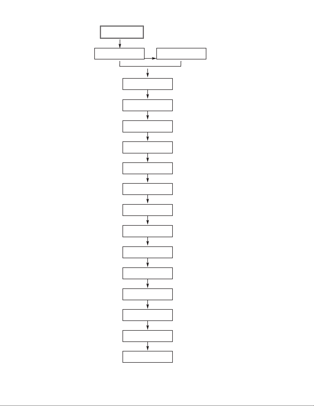
E
Quick Start
Menu
English Francais
Espanol >>
Deutsch Italiano
Portuguese >>
Measure? pH
Redox ORP
Use Preamp in?
Xmtr Sensor
Diagnostics?
On Off
Measure update
rate: 1min
Temperature in?
°C °F
Setup Wireless
Network? Yes No
Wireless Network
HART PollAddress
Network ID:
00000
Network Join Key
1 of 4: 00000000
Network Join Key
2 of 4: 00000000
Network Join Key
3 of 4: 00000000
Network Join Key
4 of 4: 00000000
Wireless Network
HART PollAddress
HART Polling
Address: 00
Page 6
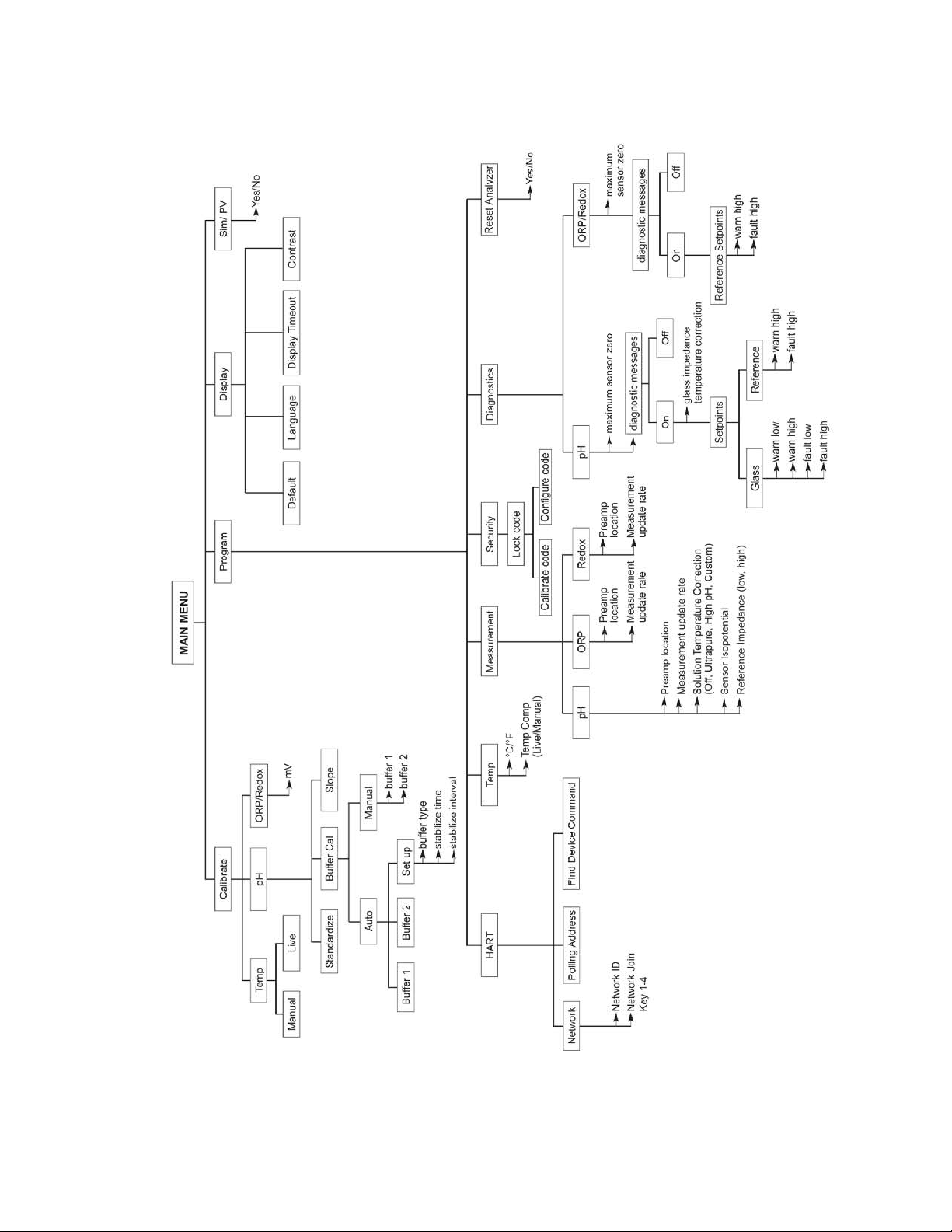
F
FIGURE 1-1. MENU TREE FOR MODEL 6081 pH Wireless TRANSMITTER
Page 7

MODEL 6081-P pH/ORP TABLE OF CONTENTS
MODEL 6081-P pH/ORP
WIRELESS TRANSMITTER
TABLE OF CONTENTS
Section Title Page
1.0 DESCRIPTION AND SPECIFICATIONS ................................................................ 1
1.1 Features and Applications........................................................................................ 1
1.2 Specifications – General ......................................................................................... 1
1.3 Specifications – Wireless ......................................................................................... 2
1.4 Specifications – Functional ...................................................................................... 2
1.5 Product Certifications............................................................................................... 3
1.6 HART Communications............................................................................................ 3
1.7 Asset Management Solutions ................................................................................. 4
2.0 INSTALLATION ...................................................................................................... 5
2.1 Considerations ......................................................................................................... 5
2.2 Unpacking and Inspection........................................................................................ 5
2.3 Pre-Installation set up .............................................................................................. 6
2.4 Mechanical Installation............................................................................................. 6
2.5 Ground the Transmitter............................................................................................ 6
2.6 Power Module Installation........................................................................................ 10
3.0 WIRING ................................................................................................................... 13
3.1 General Information ................................................................................................. 13
3.2 Sensor Wiring ......................................................................................................... 13
4.0 INTRINSICALLY SAFE INSTALLATION ................................................................ 15
5.0 COMMISSIONING .................................................................................................. 17
5.1 Network Communications ........................................................................................ 17
5.2 Device Network Configuration ................................................................................. 17
5.3 Verify Operation ....................................................................................................... 18
6.0 DISPLAY AND OPERATION ................................................................................. 19
6.1 Display ..................................................................................................................... 19
6.2 Keypad..................................................................................................................... 20
6.3 Menu – pH ............................................................................................................... 20
6.4 Information Screen Messages ................................................................................ 20
6.5 Security ....................................................................................................................21
7.0 OPERATION WITH MODEL 375 ............................................................................ 23
7.1 Note on Model 375 HART Communicator................................................................ 23
7.2 Connecting the HART Communicator...................................................................... 23
7.3 Operation ................................................................................................................. 24
Continued on the following page
i
Page 8

MODEL 6081-P pH/ORP TABLE OF CONTENTS
TABLE OF CONTENTS CONT’D
ii
8.0 PROGRAMMING THE TRANSMITTER.................................................................. 25
8.1 General .................................................................................................................... 25
8.2 Changing Start-up Settings...................................................................................... 25
8.3 Choosing and Configuring the Analytical Measurement .......................................... 26
8.4 Choosing Temperature Units and Manual or Auto Temperature Compensation...... 28
8.5 Setting a Security Code ........................................................................................... 29
8.6 Making HART-Related Settings ............................................................................... 30
8.7 Resetting Factory Calibration and Factory Default Settings .................................... 30
8.8 Selecting a Default Screen and Screen Contrast .................................................... 31
8.9 Choosing a Display Timeout .................................................................................... 32
9.0 CALIBRATION OF TEMPERATURE ...................................................................... 33
9.1 Introduction .............................................................................................................. 33
9.2 Calibration –Temperature......................................................................................... 33
10.0 CALIBRATION – pH AND ORP ............................................................................. 35
10.1 Introduction .............................................................................................................. 35
10.2 Procedure – Auto Buffer Calibration ........................................................................ 37
10.3 Procedure – Manual Two-Point Buffer Calibration .................................................. 39
10.4 Procedure – Standardization.................................................................................... 40
10.5 Procedure – Entering a Known Slope Value ............................................................ 41
10.6 ORP Calibration ....................................................................................................... 42
11.0 MAINTENANCE ...................................................................................................... 43
11.1 Overview .................................................................................................................. 43
11.2 Transmitter Maintenance ......................................................................................... 43
11.3 pH Sensor Maintenance .......................................................................................... 44
11.4 ORP Sensor Maintenance ....................................................................................... 46
11.5 Calibration................................................................................................................ 46
11.6 Power Module Replacement.................................................................................... 47
12.0 RETURN OF MATERIAL......................................................................................... 49
Page 9

iii
MODEL 6081-P pH/ORP TABLE OF CONTENTS
LIST OF FIGURES
Number Title Page
2-1 Wall Mounting Insatallation Model 6081................................................................... 8
2-2 Pipe Mounting Insatallation Model 6081 .................................................................. 9
2-3 Removing Rear Cover.............................................................................................. 10
2-4 Power Module Warning Label .................................................................................. 10
2-5 Installing the Power Module ..................................................................................... 10
2-6 Securing the rear cover ............................................................................................ 11
3-1 Model 6081 Sensor Wiring & Connection Points ..................................................... 13
6-1 Displays During Normal Operation........................................................................... 19
6-2 6081 Keypad ............................................................................................................ 20
7-1 Model 6081 Sensor Wiring & Connection Points ..................................................... 23
10-1 Calibration Slope and Offset .................................................................................... 36
11-1 Checking the Potential of the Reference Electrode.................................................. 45
Page 10

MODEL 6081-P pH/ORP TABLE OF CONTENT
iv
This page left blank intentionally
Page 11
MODEL 6081-P pH/ORP SECTION 1.0
DESCRIPTION AND SPECIFICATIONS
SECTION 1.0
DESCRIPTION AND SPECIFICATIONS
1
• HIGH ACCURACY AND RELIABILITY for monitoring
applications
• SELF-ORGANIZING NETWORK for high data
reliability and network stability
• INDUSTRY LEADING WIRELESS SECURITY
• COMPATIBLE WITH 1420 WIRELESS GATEWAY
and Emerson Process Management
WirelessHARTTMnetworks
• EASY TO READ two-line display with easy to use
menus
• WirelessHART 7 Digital Communications
• SMART Sensor Enabled
• CONTINUOUS DIAGNOSTICS monitor sensor
performance and health
1.1 FEATURES AND APPLICATIONS
The Model 6081-P transmitter is ideal for monitoring
applications, especially in hard-to-reach or costprohibitive locations. Model 6081-P measures pH and
ORP and is compatible with most Rosemount
Analytical pH and ORP sensors. The transmitter has a
rugged, cast aluminum weatherproof and corrosionresistant enclosure (NEMA 4X). The transmitter includes
a two-line 16-character display with simple and intuitive
menu screens. Plain language prompts in six (6)
local languages guide the user through the programming and calibration procedures. Model 6081 is
compatible with non-preamp pH and ORP sensors and
SMART pH sensors from Rosemount Analytical.
Installation and start-up of the Model 6081-P wireless
transmitter is simple. Just power the Model 6081-P
and assign it to a wireless network with a Model 1420
Gateway. The unit will auto-locate the most efficient
path to the host and will begin transmitting measurement
data immediately via 2.4 GHz wireless communications.
The Self-Organizing Network ensures exceptional data
reliability and network stability. All of Emerson Process
Management’s wireless devices employ Encryption,
Authentication, Verification, Anti-Jamming and Key
Management to ensure data transmission and security.
Rosemount Analytical devices include intelligent power
management to reduce power consumption and
extend power module life while delivering highly
reliable measurements with rich HART data and diagnostic information. HART digital communication allows
access to AMS (Asset Management Solutions) for live
process variables, useful diagnostics and
troubleshooting information.
1.2 SPECIFICATIONS - GENERAL
Enclosure: Cast aluminum. NEMA 4X.
Dimensions: 6.55” x 5.40” x 5.15” (166mm x 137mm
x 131mm).
Conduit Openings: 3/4” FNPT
Ambient Temperature: 32 to 122°F (0 to 50°C)
Storage Temperature: -4 to 158°F (-20 to 70°C)
Relative Humidity: 0 to 95% (non-condensing)
Weight/Shipping Weight: 7 lbs/8 lbs (3.2/3.6 kg)
RFI/EMI: EN-61326
Digital Communications: HART 7 WirelessHART
Page 12

MODEL 6081-P pH/ORP SECTION 1.0
DESCRIPTION AND SPECIFICATIONS
2
1.3 SPECIFICATIONS - WIRELESS
Output: WirelessHART V7
Transmit Rate: User selectable, 1/sec. to 1/60 min
(via 1420 Wireless Gateway or AMS)
Measurement update rate: 1/sec. to 1/10 min
Antenna: PBT/PC integrated omni-directional antenna
Radio Frequency: 2.4 GHz DSSS
Transmission distance - line of sight: about 600 ft
(ideal RF conditions and power module condition)
Power: Lithium thionyl chloride long life power module
1.4 FUNCTIONAL SPECIFICATIONS
pH Range: 0 to 14
ORP Range: -1400 to +1400mV
Compatible with Rosemount Analytical SMART pH sensors
Calibrations/standardization: The automatic buffer
recognition uses stored buffer values and their
temperature curves for the most common buffer
standards available worldwide. The transmitter also
performs a stabilization check on the sensor in
each buffer.
A manual two-point calibration is made by immersing
the sensor in two different buffer solutions and
entering the pH values. The microprocessor automatically calculates the slope which is used for
self-diagnostics. An error message will be displayed
if the pH sensor is faulty. This slope can be read on
the display and/or manually adjusted if desired.
An on-line one-point process standardization is
accomplished by entering the pH or ORP value of a
grab sample.
The following calibration methods are supported:
- Two point calibration with Low and High buffer (pH
only)
- Two point calibration with Automatic Buffer
recognition (pH only)
- Single point standardization
- Single point Temperature Adjustment
- Automatic calibration upon live connection to RAI
SMART pH sensors and upload of stored cal data
to transmitter
Automatic Temperature Compensation: External 3-wire
Pt100 RTD or Pt1000 RTD located in the sensor,
compensates the pH reading for temperature
fluctuations. Compensation covers the range -10
to 150°C (14 to 302°F). Manual temperature
compensation is also selectable.
Accuracy: ±1 mV @ 25°C ± 0.01 pH
Repeatability: ±1 mV @ 25°C ± 0.01 pH
Information and Status: Information screens display
faults and warnings, radio transmission status, network ID number, Power Module voltage, transmitter model, and software version.
Diagnostics: The internal diagnostics can detect:
RTD Failure
Glass Low Failure
Glass High Failure
Broken Glass Fault
Reference High Failure
CPU Error
High Temperature Warning
Low Temperature Warning
Glass Impedance High Warning
Glass Impedance Low Warning
Reference Impedance High Warning
EEPROM Warning
Sense Line Open Warning
Factory Cal Warning
Keyboard Warning
Once a fault or warning is detected, the display will
show a message describing the problem.
Temperature Range: -10 to 150°C (PT100 and
PT1000)
Display: 2-line, 16 character display supports display
of pH and mV units. Display shows temperature.
Approvals:
RFI/EMI: EN-61326
Note regarding ESD: “Change due to disturbance caused by electrostatic discharge will be less than 0.2 pH.”
Page 13

3
MODEL 6081-P pH/ORP SECTION 1.0
DESCRIPTION AND SPECIFICATIONS
1.5 Product Certifications
Telecommunication Compliance
All wireless devices require certification to ensure that
they adhere to regulations regarding the use of the RF
spectrum. Nearly every country requires this type of
product certification. Emerson is working with governmental agencies around the world to supply fully
compliant products and remove the risk of violating
country directives or laws governing wireless device
usage.
FCC and IC
This device complies with Part 15 of the FCC Rules.
Operation is subject to the following conditions: This
device may not cause harmful interference, this device
must accept any interference received, including interference that may cause undesired operation.
This device must be installed to ensure a minimum
antenna separation distance of 20 cm from all persons.
1.6 HART COMMUNICATIONS
1.6.1 OVERVIEW OF HART COMMUNICATION
HART (highway addressable remote transducer) V.7 supports a wireless digital communication system.
The HART protocol, originally developed by Fisher-Rosemount, is now overseen by the independent HART
Communication Foundation. The Foundation ensures that all HART devices can communicate with one another.
For more information about HART communications, call the HART Communication Foundation at (512) 794-0369.
The internet address is http://www.hartcomm.org.
1.6.2 HART INTERFACE DEVICES
HART communicators allow the user to view measurement data (pH, ORP and temperature), program the transmitter, and download information from the transmitter for transfer to a computer for analysis. Downloaded information
can also be sent to another HART transmitter. Either a hand-held communicator, such as the Rosemount Model 375,
or a computer can be used. HART interface devices operate fromthe HART taps inside the rear enclosure.
If your communicator does not recognize the Model 6081 pH/ORP transmitter, the device description library may
need updating. Call the manufacturer of your HART communication device for updates.
Page 14

MODEL 6081-P pH/ORP SECTION 1.0
DESCRIPTION AND SPECIFICATIONS
1.7 ASSET MANAGEMENT SOLUTIONS
Asset Management Solutions (AMS) is software that helps plant personnel better monitor the performance of analytical instruments, pressure and temperature transmitters, and control valves. Continuous monitoring means
maintenance personnel can anticipate equipment failures and plan preventative measures before costly breakdown maintenance is required.
AMS uses remote monitoring. The operator, sitting at a computer, can view measurement data, change program
settings, read diagnostic and warning messages, and retrieve historical data from any HART-compatible device,
including the Model 6081-P transmitter. Although AMS allows access to the basic functions of any HART compatible device, Rosemount Analytical has developed additional software for that allows access to all features of the
Model 6081-P transmitter.
AMS can play a central role in plant quality assurance and quality control. Using AMS Audit Trail, plant operators
can track calibration frequency and results as well as warnings and diagnostic messages. The information is
available to Audit Trail whether calibrations were done using the infrared remote controller, the Model 375 HART
communicator, or AMS software.
AMS operates in Windows 95. AMS communicates through a HART-compatible modem with any HART
transmitters, including those from other manufacturers. AMS is also compatible with FOUNDATION™
Fieldbus, which allows future upgrades to Fieldbus instruments.
Rosemount Analytical AMS windows provide access to all transmitter measurement and configuration variables.
The user can read raw data, final data, and program settings and can reconfigure the transmitter from anywhere
in the plant.
4
Page 15

MODEL 6081-P pH/ORP SECTION 2.0
INSTALLATION
SECTION 2.0
INSTALLATION
2.1 Considerations
2.2 Unpacking and Inspection
2.3 Pre-Installation Set Up
2.4 Mechanical Installation
2.5 Ground the Transmitter
2.6 Power Module Installation
2.1 CONSIDERATIONS
The transmitter can be commissioned before or after installation. It may be useful to commission it on the bench, before
installation, to ensure proper operation and to become familiar with its functionality. When applicable, make sure the instruments are installed in accordance with intrinsically safe or non-incendive field wiring practices. The device will be powered
whenever the power module is installed. To avoid depleting the power module, make sure it is removed when the device
is not in use.
Power module
The Model 6081 is battery powered. The power module with the wireless unit contains 2 “C” size primary
lithium/thionyl chloride batteries. Each power module contains approximately .5 grams of lithium. Under normal
conditions, the power module materials are self-contained and are not reactive as long as the power module
integrity is maintained. Care should be taken to prevent thermal, electrical or mechanical damage. Contacts
should be protected to prevent premature discharge. Use caution when handling the power module. The power
module may be damaged if dropped from heights in excess of 20 feet.
Sensor
Make sensor connections through the cable entry in the enclosure. Be sure to provide adequate clearance
for cover removal.
Environmental
Verify that the operating atmosphere of the transmitter is consistent with the appropriate hazardous locations
certifications.
2.2 UNPACKING AND INSPECTION
Inspect the shipping container. If it is damaged, contact the shipper immediately for instructions. Save the box. If
there is no apparent damage, remove the transmitter. Be sure all items shown on the packing list are present. If
items are missing, immediately notify Rosemount Analytical.
Save the shipping container and packaging. They can be reused if it is later necessary to return the transmitter to the
factory.
5
Page 16

6
2.3 PRE-INSTALLATION SETUP
2.3.1 Temperature Element
The Model 6081-P pH/ORP transmitter is compatible with sensors having Pt 100 and Pt 1000. Sensors from other
manufacturers may have a Pt 1000 RTD. For Rosemount Analytical sensors, the type of temperature element in
the sensor is printed on the tag attached to the sensor cable. For the majority of sensors manufactured by
Rosemount Analytical, the RTD IN lead is red and the RTD RTN lead is white. The Model 328A sensor has no
RTD. The Model 320HP system has a readily identifiable separate temperature element. Resistance at room
temperature for common RTDs is given in the table.
If the resistance is... the temperature element is a
about 110 ohms Pt 100 RTD
about 1100 ohms Pt 1000 RTD
2.3.2 Reference Electrode Impedance
The standard silver-silver chloride reference electrode used in most industrial and laboratory pH electrodes is low
impedance. EVERY pH and ORP sensor manufactured by Rosemount Analytical has a low impedance reference.
Certain specialized applications require a high impedance reference electrode. The transmitter must be
re-programmed to recognize the high impedance reference.
2.3.3 Preamplifier Location
pH sensors produce a high impedance voltage signal that must be preamplified before use. The signal can be
preamplified before it reaches the transmitter or it can be preamplified in the transmitter. To work properly, the
transmitter must know where preamplification occurs. Although ORP sensors produce a low impedance signal, the
voltage from an ORP sensor is amplified the same way as a pH signal.
If the sensor is wired to the transmitter through a junction box, the preamplifier is ALWAYS in either the junction
box or the sensor. Junction boxes can be attached to the sensor or installed some distance away. If the junction
box is not attached to the sensor, it is called a remote junction box. In most junction boxes used with the Model
6081-P pH/ORP, a flat, black plastic box attached to the same circuit board as the terminal strips houses the preamplifier. The preamplifier housing in the 381+ sensor is crescent shaped.
If the sensor is wired directly to the transmitter, the preamplifier can be in the sensor or in the transmitter. If the
sensor cable has a GREEN wire, the preamplifier is in the sensor. If there is no green wire, the sensor cable will
contain a coaxial cable. A coaxial cable is an insulated wire surrounded by a braided metal shield. Depending on
the sensor model, the coaxial cable terminates in either a BNC connector or in a separate ORANGE wire and
CLEAR shield.
2.4 Mechanical Installation
When choosing an installation location and position, take into account the need for access to the transmitter. For
best performance, the antenna should be vertical with some space between objects in a parallel metal plane such
as a pipe or metal framework, as the pipes or framework may adversely affect the performance of the antenna.
2.5 Ground the Transmitter
The electronics enclosure should be grounded in accordance with local and national installation codes. This can
be accomplished via the process connection, via the internal case grounding terminal, or via the external grounding terminal.
mV and RTD Inputs
Each process installation has different requirements for grounding. Use the grounding options recommended by
the facility for the specific sensor type, or begin with grounding Option 1 (the most common).
MODEL 6081-P pH/ORP SECTION 2.0
INSTALLATION
Page 17

7
WARNING
Failure to follow these installation guidelines could result in death or serious injury.
• Make sure only qualified personnel perform the installation.
Explosions could result in death or serious injury.
• Before connecting a 375 Field Communicator in an explosive atmosphere, make
sure the instruments are installed in accordance with intrinsically safe or
non-incendive field wiring practices.
• Verify that the operating atmosphere of the transmitter is consistent with the
appropriate hazardous locations certifications.
Process leaks could result in death or serious injury.
Electrical shock could cause death or serious injury.
• Use extreme caution when making contact with the leads and terminals.
This device complies with Part 15 of the FCC Rules. Operation is subject to the following
conditions: This device may not cause harmful interference, this device must accept any
interference received, including interference that may cause undesired operation.
This device must be installed to ensure a minimum antenna separation distance of 20 cm
from all persons.
MODEL 6081-P pH/ORP SECTION 2.0
INSTALLATION
NOTE:
Always use facility recommended wiring practices.
Page 18
8
MODEL 6081-P pH/ORP SECTION 2.0
INSTALLATION
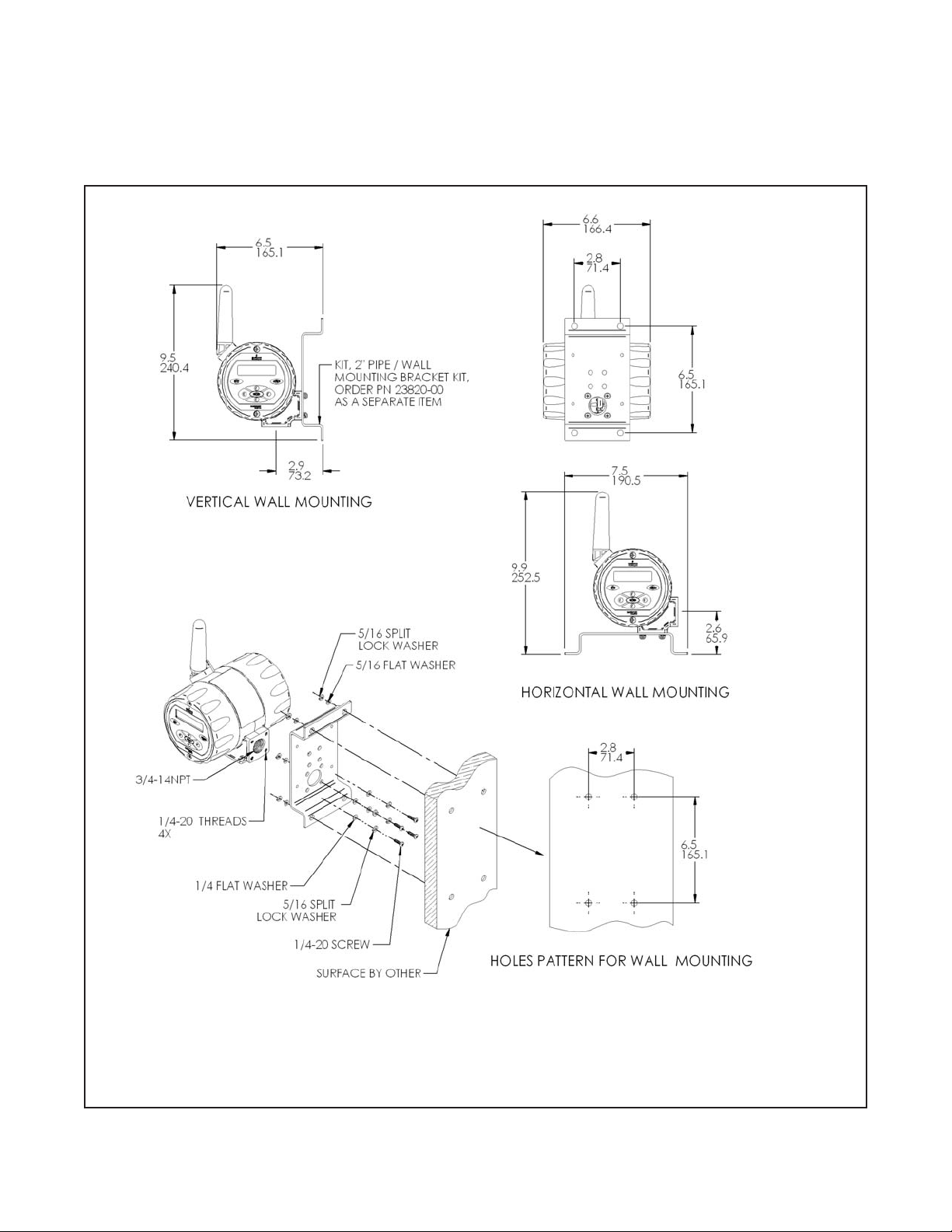
2.4.2 Mounting on a Flat Surface.
Figure 2-1. Wall Mounting Installation Model 6081. Use Pipe/Wall Mounting Bracket Kit, PN 23820-00
Note: PN 23820-00 mounting bracket kit includes mounting hardware for pipe mounting only. Wall mounting
hardware to be provided by customer. Only use suitable fasteners and hardware to securely fasten the bracket
and transmitter to the wall surface.
Page 19
9
MODEL 6081-P pH/ORP SECTION 2.0
INSTALLATION
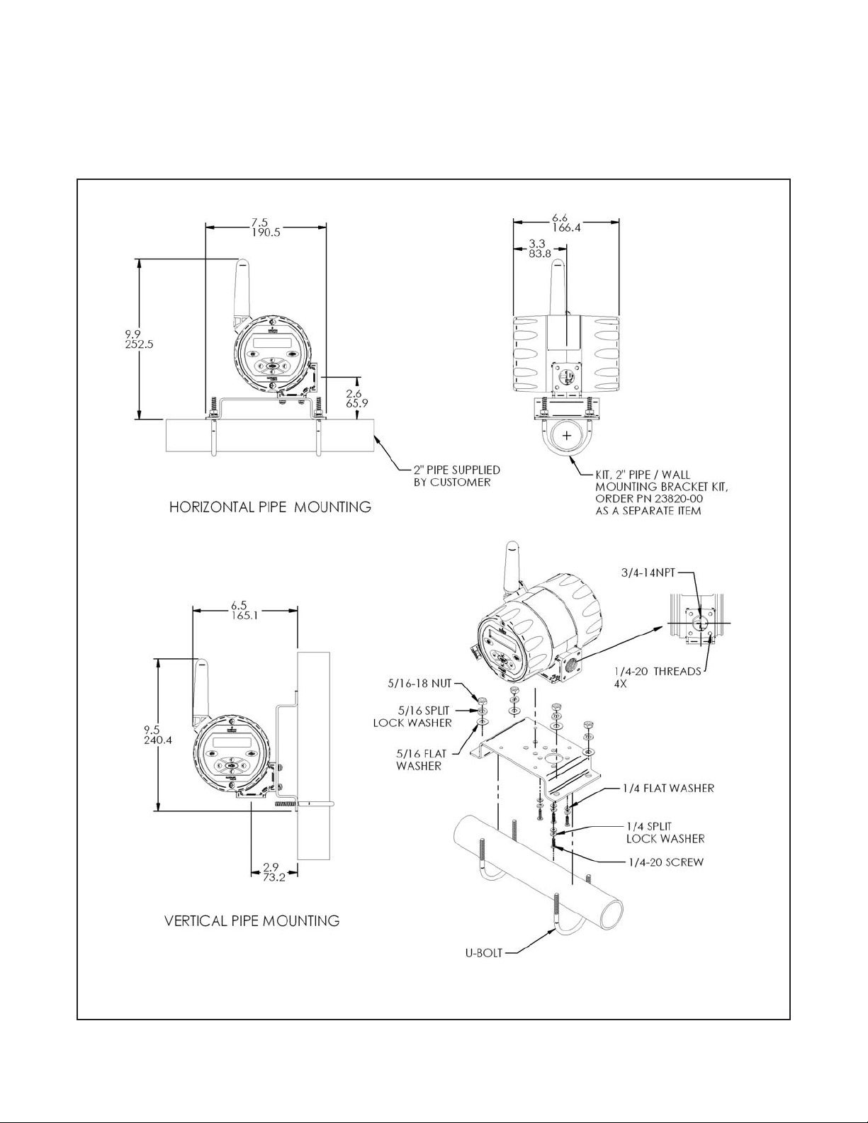
2.4.3 Pipe Mounting.
The pipe mounting kit (PN 23820-00/01) accommodates 1-1/2 to 2 in. pipe.
Figure 2-2. Pipe Mounting Installation Model 6081. Use Pipe/Wall Mounting Bracket Kit, PN 23820-00
Page 20
10
2.6 POWER MODULE INSTALLATION
The section describes the procedure for installation of the power module (part number 00753-9220-0001). The
power module should stored in a safe place with a controlled environment until the Model 6081 is ready for live
operation. For first time installation of the power module, follow these steps:
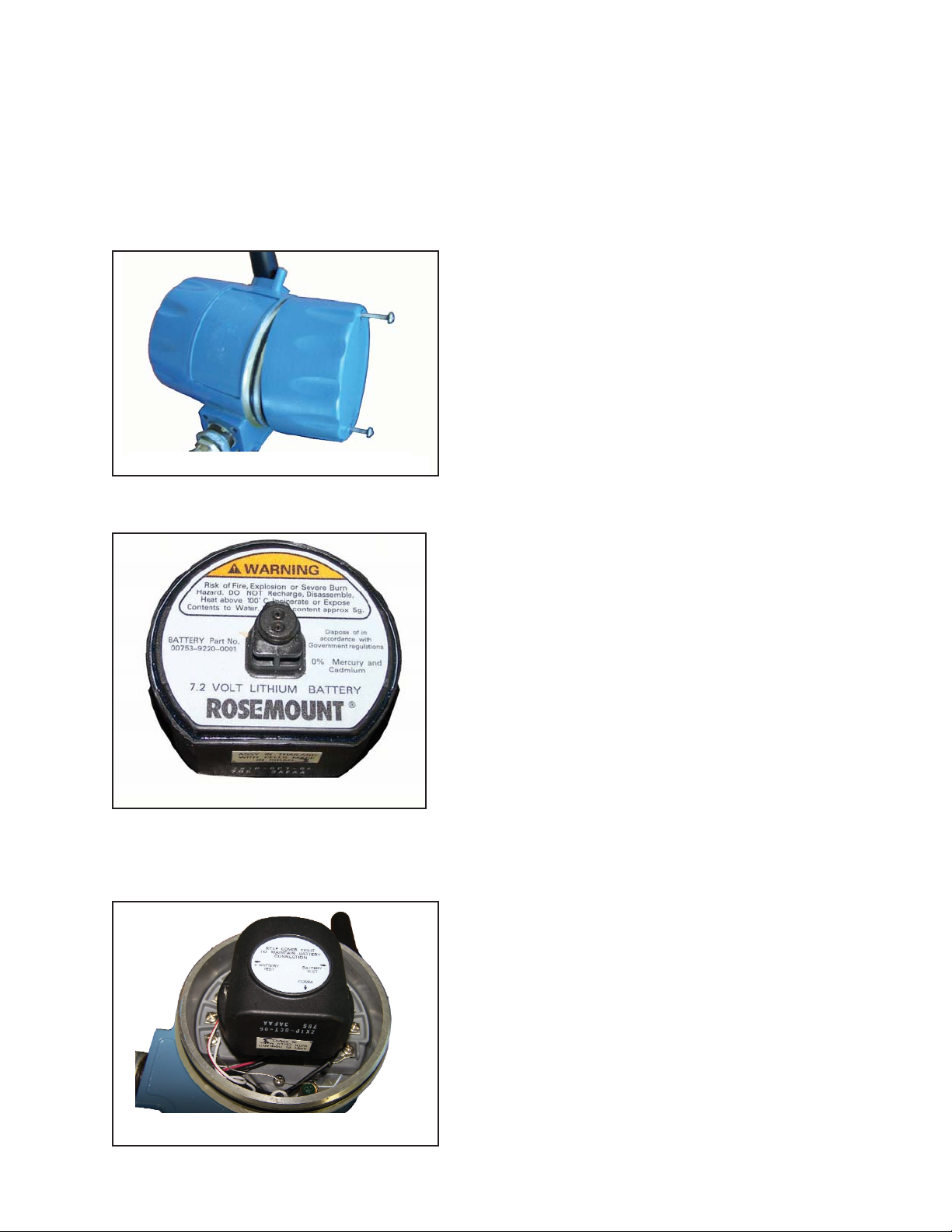
1. Unscrew the two long machine screws to remove the rear cover of the Model 6081. Separate the
rear cover from the central housing by manually prying the sections apart. Do not use screwdrivers or
tools to separate these housing parts. The parts are sealed with an o-ring.
2. Before installation, note the safety warning, disposal instructions and part information on the connectionside label of the power module.
3. With the Model 6081 front display section facing away from you, align the power module pack with the
curved surface of the pack facing towards you and the small protruding connector facing away from you.
Make sure to align the power module and its keyed connector with the connection receptacle in the middle
of the instrument’s terminal block area.
MODEL 6081-P pH/ORP SECTION 2.0
INSTALLATION
Figure 2-4. Power Module Warning Label
Figure 2-5. Installing the Power Module
Figure 2-3. Removing rear cover
Page 21
4. With gentle pressure, insert the keyed connector on the power module into the receptacle (labeled
Power Module Connection on the drawing). The power module seats in the connection receptacle with
an o-ring.
5. Confirm that the power module is fully inserted in the receptacle and properly aligned with the surrounding
terminal block.
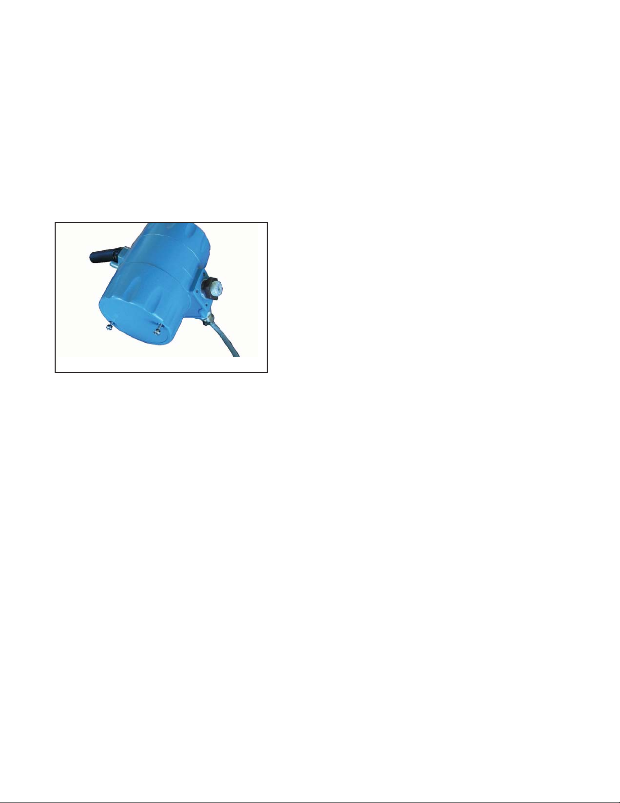
6. Replace the rear cover of the Model 6081 with the two screws to secure it to the central housing.
Tighten screws and verify operation. Correct installation the rear cover will ensure that the power modules
properly secured to power the transmitter.
To remove the power module, reverse the installation steps.
Note: A damaged or degraded o-ring may compromise the NEMA 4X/IP66 rating of the unit even when the rear
cover is correctly installed. Please take care to protect the o-ring when removing and replacing the rear cover of
the transmitter.
11
MODEL 6081-P pH/ORP SECTION 2.0
INSTALLATION
Figure 2-6 .Securing the rear cover
Page 22

12
This page left blank intentionally
MODEL 6081-P pH/ORP SECTION 2.0
INSTALLATION
Page 23
MODEL 6081-P pH/ORP SECTION 3.0
WIRING
SECTION 3.0
SENSOR WIRING
3.1 GENERAL INFORMATION
pH and ORP sensors without preamps manufactured by Rosemount Analytical can be wired directly to the Model
6081-P wireless transmitter.
3.2 SENSOR WIRING
To assist in sensor wiring, please refer to the one of the following resources:
1. Sensor Instruction Sheet – provided with each shipped sensor. Detailed wiring drawings show terminal
block connections for each sensor lead.
2. Online wiring program available at http://www.emersonprocess.com/raihome/liquid/products/wiring/Xmt
displays wiring schematics for all compatible pH sensors.
3. CD-ROM included in every shipped instrument unit contains Rosemount Analytical’s wiring program.
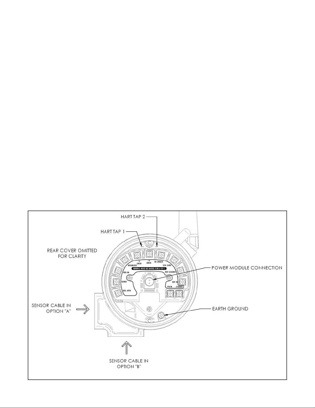
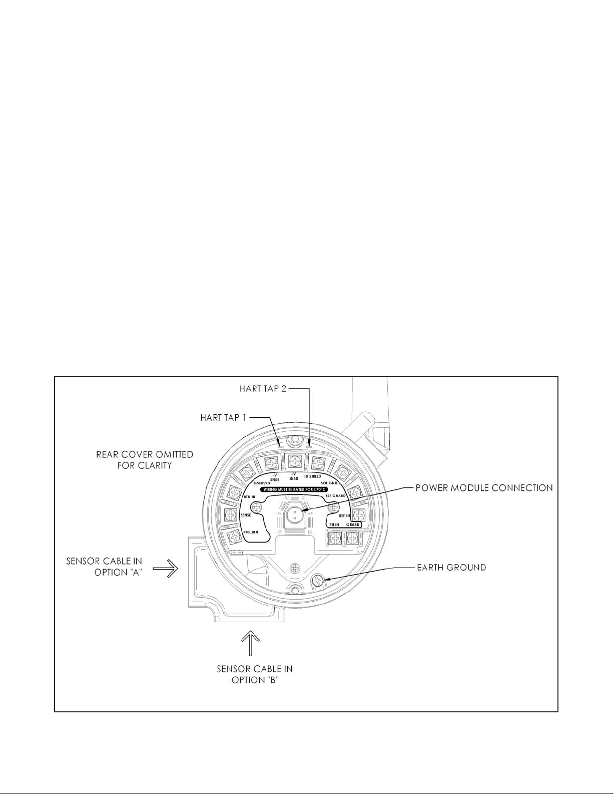
Note: all sensor wiring must be rated for ≥70 ºC.
The following drawing identifies each terminal block lead position for pH sensors.
3.1 General Information
3.2 Sensor Wiring
Figure 3-1. Model 6081 Sensor Wiring & Connection Points
13
Page 24

14
MODEL 6081-P pH/ORP SECTION 3.0
WIRING
This page left blank intentionally
Page 25

15
MODEL 6081-P pH/ORP SECTION 4.0
INTRINSICALLY SAFE & EXPLOSION PROOF
15
SECTION 4.0
INTRINSICALLY SAFE INSTALLATION
This page left blank intentionally
Page 26

16
MODEL 6081-P pH/ORP SECTION 4.0
INTRINSICALLY SAFE & EXPLOSION PROOF
This page left blank intentionally
Page 27

17
MODEL 6081-P pH/ORP SECTION 5.0
COMMISSIONING
SECTION 5.0
COMMISSIONING
5.1 Network Communications
5.2 Device Network Configuration
5.3 Verify Operation
5.1 NETWORK COMMUNICATIONS
The Model 6081 will receive any HART communications from a handheld Field Communicator, or AMS. When
using a Field Communicator, any configuration changes must be sent to the transmitter by using the Send key
(F2). AMS configuration changes are implemented when the Apply button is clicked.
AMS Wireless and Direct Connections. AMS is capable of connecting to devices either directly, using a HART
modem, or wirelessly via the 1420. When configuring on the bench using a HART modem, double click the
device icon (or right click and select Configure/Setup), then choose the Configure/Setup tab. Configure the
device settings using the Direct Connection menu. When configuring wirelessly via the 1420, double click the
device icon (or right click and select Configure/Setup), then choose the Configure/Setup tab. Configure the
device settings using the Wireless Connection menu.
The Model 6081 and all other wireless devices should be installed only after the 1420 Wireless Gateway has
been installed and is functioning properly. Wireless devices should also be powered up in order of proximity
from the 1420 Wireless Gateway, beginning with the closest device to the 1420. This will result in a simpler and
faster network installation.
5.2 DEVICE NETWORK CONFIGURATION
In order to communicate with the 1420 Wireless Gateway, and ultimately the Information System, the transmitter
must be configured to communicate with the wireless network. This step is the wireless equivalent of connecting
wires from a transmitter to the information system. Using a Field Communicator or AMS, enter the Network ID
and Join Key so that they match the Network ID and Join Key of the gateway and other devices in the network.
If the Network ID and Join Key are not identical, the transmitter will not communicate with the network. The
Network ID and Join Key may be obtained from the 1420 Wireless Gateway on the Setup>Network>Settings
page on the web server. The final device network configuration piece is the Update Rate. This by default is
1 minute. This may be changed at commissioning, or at any time via AMS or the 1420 Wireless Gateway’s web
server. The Update Rate should be between 1 second and 10 minutes. For networks of up to 100 wireless
devices, fastest Update Rate is 60 seconds. For networks of 50 or fewer devices, the fastest Update Rate is 15
seconds.
When device configuration is completed, remove the power module and replace the power module cover.
Tighten the cover to the proper tension for safety approvals. To access the Network Settings using a 375 Field
Communicator, enter the following Fast Key Sequence: 1, 3, 3.
Page 28

18
MODEL 6081-P pH/ORP SECTION 5.0
OPERATION WITH REMOTE CONTROLLER
5.3 VERIFY OPERATION
Operation can be verified in three locations, at the device via the Local Display, using the 375 Field Communicator,
or at the Gateway via the 1420 Wireless Gateway’s integrated web server.
Local Display: During normal operation, the LCD will display the PV value at the wireless transmit rate up to as
fast as 1 second intervals. Refer to LCD Screen. Access the information screens by pressing the down key to display the TAG, Device ID, Network ID, Network Join Status and Device Status screens. For Device Status screens.
375 Field Communicator: To verify device operation using a HART Field Communicator, a 6081 DD is required.
1420 Wireless Gateway: To verify device operation using the 1420 Wireless Gateway’s integrated web server,
navigate to the Explorer>Status page. This page will show whether the device has joined the network and if it is
communicating properly. If the Model 6081 was configured with the Network ID and Join Key and sufficient time
for network polling has passed, the transmitter will be connected to the network. To verify connectivity, open the
1420 Wireless Gateway’s integral web interface and navigate to the Explorer>Status page.
This page will display the transmitter’s tag, PV, SV, TV, QV, Last Update, Update Rate, Power Module Voltage, and
Status. A green status indicator means that the device is working properly. A red indicator means that there is a
problem with either the device or its communication path. For more detail on a specific device, click on the tag
name.
Troubleshooting
The most common cause of incorrect operation is the Network ID and Join Key. The Network ID and Join Key in
the device must match that of the 1420 Wireless Gateway. The Network ID and Join Key may be obtained from
the 1420 Wireless Gateway on the Setup>Network>Settings page on the web server.
18
Remove power module: After the sensor and network have been configured, remove the power module and
replace the transmitter cover. The power module should be inserted only when the device is ready to be commissioned.
Page 29

19
MODEL 6081-P pH/ORP SECTION 6.0
DISPLAY AND OPERATION
SECTION 6.0
DISPLAY AND OPERATION
6.1. DISPLAY
The Model 6081 has a two-line
display. Generally, the user can program the transmitter to show one of
three displays. If the transmitter has
been configured to measure ORP or
Redox, similar displays are available. Figure 6-1 shows the displays
available for pH.
The transmitter has information
screens that supplement the data in
the main display. Press to view
the information screens. The first
information screen shows the type
of measurement being made (pH,
ORP, Redox). The last information
screen is the software version
number.
During calibration and programming, key presses cause different
displays to appear. The displays are
self-explanatory and guide the user
step-by-step through the procedure.
FIGURE 6-1. Displays During Normal Operation
Screen A shows the pH reading, the temperature, and the output current generated by the transmitter. Screen B shows the same information as Screen A
except the output current has been substituted with the raw sensor voltage.
Screen C is most useful while troubleshooting sensor problems.
6.1 Display
6.2 Keypad
6.3 Menus - pH
6.4 Information Screen Messages
6.5 Security
Screen A
Screen B
Screen C
Temperature
Temperature
Temperature
Output current
Input current
Glass
Impedance
Reference
Impedance
pH
pH
pH
Page 30

20
6.3 MENUS - pH
The Model 6081 pH transmitter has four menus: CALIBRATE, PROGRAM, SIM PV, and DISPLAY. Under the
Calibrate and Program menus are several sub-menus. For example, under CALIBRATE, the sub-menus are
Temperature and pH or ORP/Redox. Under each sub-menu are prompts. Under PROGRAM, the sub-menus for
6081 are, Temp, Measurement, Security, HART, Diagnostics, and Reset Analyzer. The DISPLAY menu allows
the user to configure the main display information fields and to adjust the LCD display contrast.
6.4 INFORMATION SCREEN MESSAGES
Whenever a warning or fault limit has been exceeded, the transmitter displays diagnostic messages to aid in troubleshooting. “Fault” or “Warn” appears in the main display to alert the user of an adverse condition. The display
alternates between the regular display and the Fault or Warning message. If more than one warning or fault message has been generated, the messages appear alternately.
MODEL 6081-P pH/ORP SECTION 6.0
DISPLAY AND OPERATION
FIGURE 6-2. 6081 Keypad
Four arrow keys move the cursor around the screen. A blinking word or numeral show the position of the cursor. The arrow keys are also used to change the
value of a numeral. Pressing ENTER stores numbers and settings and moves
the display to the next screen. Pressing EXIT returns to the previous screen
without storing changes. Pressing MENU followed by EXIT causes the main
display to appear.
6.2 KEYPAD
Figure 6-2 shows the 6081 keypad.
Pressing EXIT ends action on the current
screen without storing changes. The display
returns to the previous screen.
If the cursor is on a number, pressing ENTER
stores the number. If the cursor is on a submenu or an item in a menu, pressing ENTER
selects it. The display changes to the next
screen
Pressing an arrow key moves the cursor
in the direction indicated. If the cursor is
on a numeral, pressing ◄ or ► moves
the cursor left or right across the number. Pressing ▼ or ▲ decreases or
increases the value of the selected digit.
Pressing MENU causes the Menu
screen to appear, or the live screen to
appear if the display has timed out.
EXIT
MENU
ENTER
Page 31

21
MODEL 6081-P pH/ORP SECTION 6.0
DISPLAY AND OPERATION
6.5 SECURITY
6.6.1 How the Security Code Works
Use security codes to prevent accidental or unwanted changes to program settings, displays, and calibration. Two
three-digit security codes can be used to do the following…
a. Allow a user to view the default display and information screens only.
b. Allow a user access to the calibration and hold menus only.
c. Allow a user access to all the menus.
1. If a security code has been programmed, pressing MENU causes the security screen to appear.
2. Enter the three-digit security code.
a. If a security code has been assigned to configure only, entering it will unlock all the menus.
b. If separate security codes have been assigned to calibrate and configure, entering the calibrate code will
allow the user access to only the calibrate and hold menus; entering the configuration code will allow the
user access to all menus.
3. If the entered code is correct, the main menu screen appears. If the code is incorrect, the Invalid Code screen
appears. The Enter Security Code screen reappears after two seconds.
Refer to section 8.5 to program the security codes.
Page 32

22
MODEL 6081-P pH/ORP SECTION 6.0
DISPLAY AND OPERATION
This page left blank intentionally
22
Page 33
23
MODEL 6081-P pH/ORP SECTION 7.0
OPERATION WITH MODEL 375
7.1 Note on Model 375 HART Communicator
7.2 Connecting the HART Communicator
7.3 Operation
SECTION 7.0
OPERATION WITH MODEL 375
7.1 Note on Model 375 HART Communicator
The Model 375 HART Communicator is a product of Emerson Process Management, Rosemount Inc. This section
contains selected information on using the Model 375 with the Rosemount Analytical Model 6081 Transmitter. For
complete information on the Model 375 Communicator, see the Model 375 instruction manual. For technical support on the Model 375 Communicator, call Rosemount Inc. at (800) 999-9307 within the United States. Support is
available worldwide on the internet at http://rosemount.com.
7.2 Connecting the HART Communicator
Figure 7-1. shows how the Model 275 or 375 Communicator connects to the output lines from the Model 6081
Transmitter.
Figure 7-1. Model 6081 Sensor Wiring & Connection Points
Page 34

24
7.3 Operation
7.3.1 Off-line and On-line Operation
The Model 375 Communicator features off-line and on-line communications. On-line means the communicator is
connected to the transmitter in the usual fashion. While the communicator is on line, the operator can view measurement data, change program settings, and read diagnostic messages. Off-line means the communicator is not
connected to the transmitter. When the communicator is off line, the operator can still program settings into the
communicator. Later, after the communicator has been connected to a transmitter, the operator can transfer the
programmed settings to the transmitter. Off-line operation permits settings common to several transmitters to be
easily stored in all of them.
7.3.2 Making HART related settings from the keypad
1. Press MENU. The main menu screen appears. Choose Program.
2. Choose >>.
3. Choose HART.
4. To display the device ID, choose DevID. To change the polling address, choose PollAddrs. To make burst
mode settings, choose Burst. To change the preamble count, choose Preamble.
MODEL 6081-P pH/ORP SECTION 7.0
OPERATION WITH MODEL 375
Page 35

25
MODEL 6081-P pH/ORP SECTION 8.0
PROGRAMMING THE TRANSMITTER
SECTION 8.0
PROGRAMMING THE TRANSMITTER
8.1 General
8.2 Changing Start-up Settings
8.3 Choosing and Configuring the Analytical Measurement
8.4 Choosing Temperature Units and Manual or Auto Temperature Compensation
8.5 Setting a Security Code
8.6 Making HART-Related Settings
8.7 Resetting Factory Calibration and Factory Default Settings
8.8 Selecting a Default Screen and Screen Contrast
8.9 Choosing a Display Timeout
8.1 GENERAL
This section describes how to program the transmitter using the keypad.
1. Select the measurement to be made (pH, ORP, or Redox).
2. Choose temperature units and automatic or manual temperature mode.
3. Set a security code.
4. Make certain settings relating to HART communication.
5. Resetting factory default settings.
6. Selecting a default display screen and adjusting screen contrast.
8.2 CHANGING START-UP SETTINGS
When the Model 6081 is powered up for the first time, startup screens appear. The screens prompt the user
to enter the measurement being made, to identify the sensor being used, to select automatic or manual pH
correction and to select temperature units. If incorrect settings were entered at startup, enter the correct settings now. To change the measurement, refer to Section 8.4.
Page 36

26
MODEL 6081-P pH/ORP SECTION 8.0
PROGRAMMING THE TRANSMITTER
8.3 CHOOSING AND CONFIGURING THE ANALYTICAL MEASUREMENT
8.3.1 Purpose
This section describes how to do the following:
1. Configure the transmitter to measure pH, ORP, or Redox.
2. Determine the location of the preamp.
3. If pH was selected, there are additional selections and settings to make:
a. choose a solution temperature correction curve or set a temperature coefficient constant
b. choose sensor isopotential
c. set reference impedance low or high
8.3.2 Definitions
1. MEASUREMENT. The transmitter can be configured to measure pH, ORP or Redox (opposite sign of ORP).
2. pH SETTINGS. If pH is selected, there are additional settings to make.
a. PREAMPLIFIER. The raw pH signal is a high impedance voltage. A voltage follower or preamplifier, locat-
ed either in the sensor or transmitter, converts the high impedance signal into a low impedance one.
Normally, high impedance signals should be sent no further than about 15 feet.
b. REFERENCE OFFSET. Ideally, a pH sensor in pH 7 buffer should have a voltage of 0 mV. The difference
between the measured voltage in pH 7 buffer and the ideal value is the reference offset. Typically, the reference offset is less than 60 mV.
c. DIAGNOSTICS. The 6081 continuously monitors the pH sensor for faults. If it detects a fault, the trans-
mitter displays a fault message.
d. GLASS IMPEDANCE. The transmitter monitors the condition of the pH-sensitive glass membrane in the
sensor by continuously measuring the impedance across the membrane. Typical impedance is between
100 and 500 MΩ. Low impedance (<10 MΩ) implies the glass bulb has cracked and the sensor must be
replaced. An extremely high impedance (>1000 MΩ) implirs the sensor is aging and may soon need
replacement. High impedance might also mean that the glass membrane is no longer immersed in the
process liquid.
3. INPUT FILTER. The raw sensor current can be filtered to reduce noise. Filtering also increases the response
time. The filter is the time required for the input to reach 63% of its final reading following a step change.
Page 37

27
MODEL 6081-P pH/ORP SECTION 8.0
PROGRAMMING THE TRANSMITTER
8.3.3 Procedure to configure: Measurement.
To choose a menu item, move the cursor to the item and press ENTER.
To store a number or setting, press ENTER.
1. Press MENU. The main menu screen appears. Choose Program.
2. Choose Measurement.
3. Choose pH, Redox, or ORP.
If you chose pH, do steps 5 through 9.
If you chose ORP or Redox, do step 10.
4. Enter the correct preamplifier location. The default setting is within the transmitter.
5. For measure sampling rate, select 1 second to 10 minutes by scrolling through choices. Press ENTER.
6. Choose Soln Temp Corr or Sensor Isoptntl.
7. For Soln Temp Corr, choose Off, UltraPure, HighpH, or Custom. For Custom, enter the desired temperature coefficient.
8. For Sensor Isoptntl, enter the desired sensor isopotential pH. Do not change the sensor isopotential pH
unless the sensor is known to have an isopotential pH different from 7.00.
9. Choose Low or High Reference Impedance to match the installed sensor’s reference impedance signal. The
default setting is Low Impedance to match standard pH sensors. Press EXIT twice to return to the Program
menu.
10. If Redox or ORP was selected, there are no further settings to make. Press EXIT to return to the Program
menu.
11. To return to the main display, press MENU followed by EXIT.
Page 38

28
MODEL 6081-P pH/ORP SECTION 8.0
PROGRAMMING THE TRANSMITTER
8.4 CHOOSING TEMPERATURE UNITS AND MANUAL OR AUTOMATIC TEMPERATURE
COMPENSATION
8.4.1 Purpose
This section describes how to do the following:
1. Choose temperature display units (°C or °F).
2. Choose automatic or manual temperature compensation.
3. Enter a temperature for manual temperature compensation
8.4.2 Definitions
1. AUTOMATIC TEMPERATURE COMPENSATION. The analyzer uses a temperature-dependent factor to convert measured cell voltage to pH. In automatic temperature compensation, the analyzer measures the temperature and automatically calculates the correct conversion factor. For maximum accuracy, use automatic
temperature compensation.
2. MANUAL TEMPERATURE COMPENSATION. In manual temperature compensation, the analyzer converts
measured voltage to pH using the temperature entered by the user. It does not use the actual process temperature. Do NOT use manual temperature compensation unless the process temperature varies no more than
about ±2°C or the pH is between 6 and 8. Manual temperature compensation is useful if the sensor temperature element has failed and a replacement sensor is not available. If manual temperature correction is selected,
the display will not show the measured temperature. It will show the manually entered value.
8.4.3 Procedure: Temperature.
1. Press MENU. The main menu screen appears. Choose Program.
2. Choose Temp.
3. Choose °C/F to change temperature units. Choose Live/Manual to turn on (Live) or turn off (Manual) automatic temperature compensation.
a. If °C/F is chosen, select °C or °F in the next screen.
b. If Live/Manual is chosen, select Live or Manual in the next screen.
c. If Manual is chosen, enter the temperature in the next screen. The temperature entered in this step will
be used in all subsequent measurements, no matter what the process temperature is.
To choose a menu item, move the cursor to the item and press ENTER.
To store a number or setting, press ENTER.
Page 39

29
MODEL 6081-P pH/ORP SECTION 8.0
PROGRAMMING THE TRANSMITTER
8.5.2 Procedure: Setting a security code.
1. Press MENU. The menu screen appears. Choose Program.
2. Choose >>.
3. Choose Security.
4. Choose Calib or Config.
a. If you chose Calib, enter a three-digit security code.
b. If you chose Config, enter a three-digit security code.
5. To return to the main display, press MENU the EXIT.
8.5 SETTING A SECURITY CODE
8.5.1 Purpose
This section describes how to set a security code. There are three levels of security:
a. A user can view the default display and information screens only.
b. A user has access to the calibration menus only.
c. A user has access to all menus.
The security code is a three-digit number. The table shows what happens when security codes are assigned to
Calib (calibration) and Config (configure). In the table XXX and YYY are the assigned security codes.
Code assignments
Calib Config What happens
000 XXX User enters XXX and has access to all menus.
XXX YYY User enters XXX and has access to calibration menus only. User enters YYY and has access to
all menus.
XXX 000 User needs no security code to have access to all menus.
000 000 User needs no security code to have access to all menus.
Page 40

30
MODEL 6081-P pH/ORP SECTION 8.0
PROGRAMMING THE TRANSMITTER
8.6 MAKING HART RELATED SETTINGS
For more information refer to Sec. 1.0
8.7 RESETTING FACTORY CALIBRATION AND FACTORY DEFAULT SETTINGS
8.7.1 Purpose
This section describes how to install factory calibration and default values. The process also clears all fault
messages and returns the display to the first quick start screen.
8.7.2 Procedure: Installing default settings.
1. Press MENU. The menu screen appears. Choose Program.
2. Choose >>.
3. Choose >>.
4. Choose ResetTransmitter.
5. Choose Yes or No. Choosing Yes clears previous settings and calibrations and returns the transmitter to the
first quick start screen.
Page 41

31
MODEL 6081-P pH/ORP SECTION 8.0
PROGRAMMING THE TRANSMITTER
8.8 SELECTING A DEFAULT SCREEN AND SCREEN CONTRAST
8.8.1 Purpose
This section describes how to do the following:
1. Set a default screen. The default screen is the screen shown during normal operation. The 6081 allows the
user to choose from a number of screens. Which screens are available depends on the measurement the
transmitter is making.
2. Change the screen contrast.
8.8.2 Procedure: Choosing a display screen.
1. Press MENU. The menu screen appears. Choose Display.
2. Choose Default Display.
3. Press until the desired screen appears. Press ENTER.
4. The display returns to the screen in step 2. Press MENU then EXIT to return to the main display.
8.8.3 Procedure: Changing screen contrast.
1. Press MENU. The menu screen appears. Choose Display.
2. Choose Display Contrast.
3. To increase the contrast, select darker. Press ENTER. Each key press increases the contrast. To reduce the
contrast, select lighter, Press ENTER. Each key press decreases the contrast.
4. To return to the main display, press MENU then EXIT.
NOTE:
Screen contrast can also be adjusted from the main display. Press MENU
and at the same time to increase contrast. Press MENU and at the
same time to decrease contrast. Repeatedly pressing the arrow key increases
or reduces the contrast.
Page 42

32
This page left blank intentionally
MODEL 6081-P pH/ORP SECTION 8.0
PROGRAMMING THE TRANSMITTER
32
8.9 CHOOSING A DISPLAY TIMEOUT
8.9.1 Purpose
The local transmitter screen will timeout to preserve power module life. The transmitter will continue to receive
measurement inputs and continue to transmit to the wireless network as programmed.
8.9.2 Procedure: Programming the display timeout
1. Press MENU to activate the live display.
2. Press MENU again. The menu screen appears. Choose Display.
3. Choose >>.
4. Select Display Timeout. Press ENTER.
5. Using the up and down keys, enter a value from 01 sec. to 999 sec. Press ENTER.
6. To return to the main display, press MENU then EXIT.
Page 43

33
MODEL 6081-P pH/ORP SECTION 9.0
CALIBRATION – TEMPERTURE
SECTION 9.0
CALIBRATION — TEMPERATURE
9.1 INTRODUCTION
The Calibrate Menu allows the user to calibrate the pH, ORP (or redox), and temperature response of the sensor.
9.2 CALIBRATING TEMPERATURE
9.2.1 Purpose
Temperature affects the measurement of pH in three ways.
1. The analyzer uses a temperature dependent factor to convert measured cell voltage to pH. Normally, a slight
inaccuracy in the temperature reading is unimportant unless the pH reading is significantly different from 7.00.
Even then, the error is small. For example, at pH 12 and 25°C, a 1°C error produces a pH error less than ±0.02.
2. During auto calibration, the 6081 recognizes the buffer being used and calculates the actual pH of the buffer
at the measured temperature. Because the pH of most buffers changes only slightly with temperature, reasonable errors in temperature do not produce large errors in the buffer pH. For example, a 1°C error causes
at most an error of ±0.03 in the calculated buffer pH.
3. The 6081 can be programmed to calculate and display pH at a reference temperature (25°C). The maximum
change in solution pH with temperature is about ±0.04 pH/°C, so a 1°C temperature error does introduce a
small error. However, the major source of error in solution temperature compensation is using an incorrect temperature coefficient.
Temperature affects the measurement of ORP in a complicated fashion that is best determined empirically.
Without calibration the accuracy of the temperature measurement is about ±0.4°C. Calibrate the sensor/analyzer
combination if
1. ±0.4°C accuracy is not acceptable
2. the temperature measurement is suspected of being in error. Calibrate temperature by making the analyzer
reading match the temperature measured with a standard thermometer.
9.1 Introduction
9.2 Calibrating Temperature
Page 44

34
MODEL 6081-P pH/ORP SECTION 9.0
CALIBRATION – TEMPERTURE
9.2.2 Procedure
1. Remove the sensor from the process. Place it in an insulated container of water along with a calibrated thermometer. Submerge at least the bottom two inches of the sensor. Stir continuously.
2. Allow the sensor to reach thermal equilibrium. For some sensors, the time constant for a change in temperature is 5 min., so it may take as long as 30 min. for temperature equilibration.
3. If the sensor cannot be removed from the process, measure the temperature of a flowing sample taken from
a point as close to the sensor as possible. Let the sample continuously overflow an insulated container holding a calibrated thermometer.
4. Change the 6081 display to match the calibrated thermometer using the procedure below.
1. Press MENU. The menu screen appears. Choose Calibrate.
2. Choose Temp.
3. If transmitter was programmed in Section 8.4 to use the actual process temperature, go to step 7.
If the transmitter was programmed to use a temperature entered by the user, go to step 9.
4. To calibrate the temperature, change the number in the second line to match the temperature measured with
the standard thermometer. Press ENTER.
5. Press MENU then EXIT to return to the main display.
6. If the temperature value shown in the display is not correct, use the arrow keys to change it to the desired
value. The transmitter will use the temperature entered in this step in all measurements and calculations, no
matter what the true temperature is.
7. Press MENU then EXIT to return to the main display.
Page 45

35
MODEL 6081-P pH/ORP SECTION 10.0
CALIBRATION – PH
SECTION 10.0
CALIBRATION — pH AND ORP
10.1 INTRODUCTION
For pH sensors, two-point buffer calibration is standard. Both automatic calibration and manual calibration are
available. Auto calibration avoids common pitfalls and reduces errors. Its use is recommended. In auto calibration
the 6081 calculates the actual pH of the buffer from the nominal value entered by the user and does not accept
calibration data until readings are stable. In manual calibration the user enters buffer values and judges when readings are stable. The pH reading can also be standardized, that is, forced to match the reading from a referee instrument. Finally, if the user knows the electrode slope (at 25°C), he can enter it directly.
The ORP calibration is a single-point calibration against an ORP standard.
A new pH sensor must be calibrated before use. Regular recalibration is also necessary.
A pH measurement cell (pH sensor and the solution to be measured) can be pictured as a battery with an extreme-
ly high internal resistance. The voltage of the battery depends on the pH of the solution. The pH meter, which is
basically a voltmeter with a very high input impedance, measures the cell voltage and calculates pH using a conversion factor. The actual value of the voltage-to-pH conversion factor depends on the sensitivity of the pH sensing element (and the temperature). The sensing element is a thin, glass membrane at the end of the sensor. As
the glass membrane ages, the sensitivity drops. Regular recalibration corrects for the loss of sensitivity. pH calibration standards, also called buffers, are readily available.
In automatic calibration the transmitter recognizes the buffer and uses temperature-corrected pH values in the calibration. The table below lists the standard buffers the controller recognizes. The controller also recognizes several technical buffers: Merck, Ingold, and DIN 19267. Temperature-pH data stored in the controller are valid between
at least 0 and 60°C.
10.1 Introduction
10.2 Procedure – Auto Buffer Calibration
10.3 Procedure – Manual Two-Point Buffer Calibration
10.4 Procedure – Standardization
10.5 Procedure – Entering a Known Slope Value
10.6 ORP Calibration
pH at 25°C Standard(s)
(nominal pH)
1.68 NIST, DIN 19266, JSI 8802, BSI (see note 1)
3.56 NIST, BSI
3.78 NIST
4.01 NIST, DIN 19266, JSI 8802, BSI
6.86 NIST, DIN 19266, JSI 8802, BSI
7.00 (see note 2)
7.41 NIST
9.18 NIST, DIN 19266, JSI 8802, BSI
10.01 NIST, JSI 8802, BSI
12.45 NIST, DIN 19266
Note 1: NIST is National Institute of Standards,
DIN is Deutsche Institute für Normung, JSI is
Japan Standards Institute, and BSI is British
Standards Institute.
Note 2: pH 7 buffer is not a standard buffer. It is
a popular commercial buffer in the United
States.
Page 46

36
MODEL 6081-P pH/ORP SECTION 10.0
CALIBRATION – PH
FIGURE 10-1. Calibration Slope and Offset
During automatic calibration, the transmitter also measures
noise and drift and does not accept calibration data until readings are stable. Calibration data will be accepted as soon as the
pH reading is constant to within the factory-set limits of 0.02 pH
units for 10 seconds. The stability settings can be changed.
In manual calibration, the user judges when pH readings are
stable. He also has to look up the pH of the buffer at the
temperature it is being used and enter the value in the transmitter.
Once the transmitter completes the calibration, it calculates the
calibration slope and offset. The slope is reported as the slope
at 25°C. Figure 10-1 defines the terms.
The transmitter can also be standardized. Standardization is the
process of forcing the transmitter reading to match the reading
from a second pH instrument. Standardization is sometimes
called a one-point calibration.
Page 47

37
MODEL 6081-P pH/ORP SECTION 10.0
CALIBRATION – PH
10.2 PROCEDURE — AUTO BUFFER CALIBRATION
1. Obtain two buffer solutions. Ideally, the buffer values should bracket the range of pH values to be measured.
2. Remove the pH sensor from the process liquid. If the process and buffer temperatures are appreciably different, place the sensor in a container of tap water at the buffer temperature. Do not start the calibration until the
sensor has reached the buffer temperature. Thirty minutes is usually adequate.
3. Press MENU. The main menu appears. Choose Calibrate.
4. Choose pH.
5. Choose BufferCal.
6. Choose Auto.
7. To continue with the calibration, choose Buffer1.Then go to step 8. To change stability criteria, choose Setup
and go to step 19.
8. Rinse the sensor with water and place it in buffer 1. Be sure the glass bulb and the reference junction are completely submerged. Swirl the sensor.
9. The screen at left is displayed with “Wait” flashing until the reading is stable. The default stability setting is
<0.02 pH change in 10 sec. To change the stability criteria, go to step 19. When the reading is stable, the
screen in step 10 appears.
10. The top line shows the actual reading. The transmitter also identifies the buffer and displays the nominal buffer
value (buffer pH at 25°C). If the displayed value is not correct, press or to display the correct value. The
nominal value will change, for example from 7.01 to 6.86 pH. Press ENTER to store.
11. The screen at left appears momentarily.
12. The screen at left appears. Remove the sensor from Buffer 1, rinse it with water, and place it in Buffer 2. Be
sure the glass bulb and the reference junction are completely submerged. Swirl the sensor. Choose Buffer2.
13. The screen at left is displayed with “Wait” flashing until the reading is stable. When the reading is stable, the
screen in step 14 appears.
14. The top line shows the actual reading. The transmitter also identifies the buffer and displays the nominal buffer
value (buffer pH at 25°C). If the displayed value is not correct, press or to display the correct value. The
nominal value will change, for example from 9.91 to 10.02 pH. Press ENTER to store.
15. The screen at the left appears momentarily.
16. If the calibration was successful, the transmitter will display the offset and slope (at 25°). The display will return
to the screen in step 6.
17. If the slope is out of range (less than 45 mV/pH or greater than 60 mV/pH) or if the offset exceeds the value programmed in Section 8.4, an error screen appears. The display then returns to the screen in step 6.
18. To return to the main display, press MENU then EXIT.
19. Choosing Setup in step 7 causes the Buffer Stabilize screen to appear. The transmitter will not accept calibration data until the pH reading is stable. The default requirement is a pH change less than 0.02 units in 10
seconds. To change the stability criteria:
a. Enter the desired stabilization time
b. Enter the minimum amount the reading is permitted to change in the time specified in step 19a.
20. To return to the main display, press MENU then EXIT.
Page 48

38
10.3 PROCEDURE — MANUAL TWO-POINT BUFFER CALIBRATION
1. Obtain two buffer solutions. Ideally, the buffer values should bracket the range of pH values to be measured.
2. Remove the pH sensor from the process liquid. If the process and buffer temperatures are appreciably different,
place the sensor in a container of tap water at the buffer temperature. Do not start the calibration until the sensor
has reached the buffer temperature. Thirty minutes is usually adequate. Make a note of the temperature.
3. Press MENU. The main menu appears. Choose Calibrate.
4. Choose pH.
5. Choose BufferCal.
6. Choose Manual.
7. Choose Buffer1.
8. Rinse the sensor with water and place it in buffer 1. Be sure the glass bulb and reference junction are completely submerged. Swirl the sensor.
9. The reading in the top line is the live pH reading. Wait until the live reading is stable. Then, use the arrow keys
to change the reading in the second line to the match the pH value of the buffer. The pH of buffer solutions is
a function of temperature. Be sure to enter the pH of the buffer at the actual temperature of the buffer.
10. Remove the sensor from buffer 1 and rinse it with water. Place it in buffer 2. Be sure the glass bulb and the
reference junction are completely submerged. Swirl the sensor. Choose Buffer2.
11. The reading in the top line is the live pH reading. Wait until the live reading is stable. Then, use the arrow keys
to change the reading in the second line to the match the pH value of the buffer. The pH of buffer solutions is
a function of temperature. Be sure to enter the pH of the buffer at the actual temperature of the buffer.
12. The screen at left appears momentarily.
13. If the calibration was successful, the transmitter will display the offset and slope (at 25°). The display will return
to the screen in step 5.
14. If the slope is out of range (less than 45 mV/pH or greater than 60 mV/pH) or if the offset exceeds the value programmed in Section 8.4, an error screen appears. The display then returns to the screen in step 6.
15. To return to the main display, press MENU then EXIT.
MODEL 6081-P pH/ORP SECTION 10.0
CALIBRATION – PH
Page 49

39
MODEL 6081-P pH/ORP SECTION 10.0
CALIBRATION – PH
10.4 PROCEDURE — STANDARDIZATION
1. The pH measured by the transmitter can be changed to match the reading from a second or referee instrument. The process of making the two readings agree is called standardization.
2. During standardization, the difference between the two values is converted to the equivalent voltage. The voltage, called the reference offset, is added to all subsequent measured cell voltages before they are converted
to pH. If after standardization the sensor is placed in a buffer solution, the measured pH will differ from the
buffer pH by an amount equivalent to the standardization offset.
3. Install the pH sensor in the process liquid.
4. Once readings are stable, measure the pH of the liquid using a referee instrument.
5. Because the pH of the process liquid may change if the temperature changes, measure the pH of the grab
sample immediately after taking it.
6. For poorly buffered samples, it is best to determine the pH of a continuously flowing sample from a point as
close as possible to the sensor.
7. Press MENU. The main menu appears. Choose Calibrate.
8. Choose pH.
9. Choose Standardize.
10. The top line shows the present reading. Use the arrow keys to change the pH reading in the second line to
match the pH reading from the referee instrument.
11. The screen at left appears if the entered pH was greater than 14.00 or if the mV offset calculated by the transmitter during standardization exceeds the reference offset limit programmed into the transmitter. The display
then returns to step 10. Repeat the standardization. To change the reference offset from the default value (60
mV), see section 8.4.
12. If the entry was accepted the display returns to step 9.
13. To return to the main display, press MENU then EXIT.
Page 50

40
10.5 PROCEDURE — ENTERING A KNOWN SLOPE VALUE.
1. If the electrode slope is known from other measurements, it can be entered directly into the transmitter. The
slope must be entered as the slope at 25°C. To calculate the slope at 25°C from the slope at temperature t°C,
use the equation:
slope at 25°C = (slope at t°C)
Changing the slope overrides the slope determined from the previous buffer calibration.
2. Press MENU. The main menu appears. Choose Calibrate.
3. Choose pH.
4. Choose slope.
5. The screen at left appears briefly.
6. Change the slope to the desired value. Press ENTER.
7. The slope must be between 45 and 60 mV/pH. If the value entered is outside this range, the screen at left
appears.
8. If the entry was accepted, the screen at left appears.
9. To return to the main display, press MENU then EXIT.
298
t°C + 273
MODEL 6081-P pH/ORP SECTION 10.0
CALIBRATION – PH
Page 51

41
MODEL 6081-P pH/ORP SECTION 10.0
CALIBRATION – PH
10.6 ORP CALIBRATION
10.6.1 Purpose
1. For process control, it is often important to make the measured ORP agree with the ORP of a standard solution.
2. During calibration, the measured ORP is made equal to the ORP of a standard solution at a single point.
10.6.2 Preparation of ORP standard solutions
ASTM D1498-93 gives procedures for the preparation of iron (II) - iron (III) and quinhydrone ORP standards. The
iron (II) - iron (III) standard is recommended. It is fairly easy to make, is not particularly hazardous, and has a shelf
life of about one year. In contrast, quinhydrone standards contain toxic quinhydrone and have only an eight-hour
shelf life.
Iron (II) - iron (III) standard is available from Rosemount Analytical as PN R508-16OZ. The ORP of the standard
solution measured against a silver-silver chloride reference electrode is 476±20mV at 25°C. The redox potential is
-476±20mV at 25°C.
10.6.3 Procedure
1. Press MENU. The main menu screen appears. Choose Calibrate.
2. Choose ORP.
3. The top line shows the actual ORP or redox potential (Live). Once the reading is stable, change the number
in the second line to the desired value. Press ENTER.
4. The screen on the left will appear briefly.
5. The display returns to the Cal Sensor screen. Press EXIT. Choose the other sensor and repeat steps 2 through 4.
Page 52

This page left blank intentionally
42
MODEL 6081-P pH/ORP SECTION 10.0
CALIBRATION – PH
Page 53

43
MODEL 6081-P pH/ORP SECTION 11.0
MAINTENANCE
SECTION 11.0
MAINTENANCE
11.1 OVERVIEW
This section gives general procedures for routine maintenance of the 6081-P pH/ORP transmitter and pH and
ORP sensors. The transmitter needs almost no routine maintenance. Sensors require periodic inspection and
cleaning. The calibration of the transmitter-sensor combination should be checked regularly, and the loop recalibrated if necessary.
11.2 TRANSMITTER MAINTENANCE
Periodically clean the transmitter window and housing as needed with a cloth dampened with water. Do not use
abrasive cleaning solutions. The O-rings and sealing surfaces must be kept clean or moisture may enter the
electronic enclosure.
11.1 Overview
11.2 Transmitter Maintenance
11.3 pH Sensor Maintenance
11.4 ORP Sensor Maintenance
11.5 Calibration
11.6 Power Module Replacement
Page 54

44
MODEL 6081-P pH/ORP SECTION 11.0
MAINTENANCE
11.3 pH SENSOR MAINTENANCE
11.3.1 Frequency of Cleaning
The frequency at which a sensor should be inspected and cleaned can be determined only by experience. If the
process liquid coats or fouls the sensor, frequent cleaning may be necessary. If the process does not contain a
high level of suspended solids, the need for regular cleaning will be less. Often an increase in glass impedance
indicates the electrode is becoming fouled and needs cleaning. Refer to Section 12.4 for a description of the
glass impedance diagnostic.
11.3.2 Cleaning Procedures
When using acid or alkaline solvents, be careful to keep the solvent away from the liquid junction. If the cleaning solvent contacts the junction, hydrogen ions (acid solvent) or hydroxide ions (alkaline solvent) will diffuse into the junction. Because hydrogen and hydroxide ions have much greater mobility than other ions, they produce a large junction
potential. When the electrode goes back in service, the hydrogen or hydroxide ions slowly diffuse out of the junction,
causing the liquid junction potential and the pH reading to drift. It may take hours or days for the reading to stabilize.
For a discussion of the influence of ion mobility on liquid junction potentials, see Section 13.4.
Consult the sensor instruction manual for additional information.
Always recalibrate the sensor after cleaning. If the sensor was cleaned with detergent or acid, soak the sensor in pH
4 or pH 7 buffer for at least an hour before calibrating.
PROBLEM
CLEANING SUGGESTIONS
Loose scale or debris
Use a stream of water from a wash bottle to rinse away solids from the tip of the
sensor. If water does not work, gently wipe the glass bulb and liquid junction with a
soft cloth, tissue, cotton-tipped swab, or a soft bristle brush.
Oil and grease Wash the glass bulb with mild detergent solution and rinse thoroughly with water.
Hard scale (carbonate sulfate
scales and corrosion products)
If wiping the sensor tip with a tissue or cotton swab does not remove the scale,
soak the glass bulb ONLY in a solution of 5% hydrochloric acid. To prepare the
acid solution, add 15 mL of concentrated hydrochloric acid to 85 mL of water.
Keep the acid away from the liquid junction and from any stainless steel portions
of the sensor. Rinse the sensor thoroughly with deionized water. Some scales (for
example, calcium sulfate) cannot be removed easily with acid. Soaking the glass
bulb in a 2% solution of disodium EDTA may be helpful.
Page 55

45
11.3.3 Checking the Reference Electrode.
Some processes contain substances, for example, sulfides, that poison the reference electrode. Poisoning alters the
electrode potential. For example, sulfide poisoning converts the reference electrode from a silver/silver chloride electrode into a silver/silver sulfide electrode, causing a shift in potential of several hundred millivolts.
A good way to check for poisoning is to compare the voltage of the reference electrode with a silver/silver chloride
electrode that is known to be good. The reference electrode from a new sensor is the best choice. To check the suspect electrode, place both sensors in a beaker containing buffer or a solution of potassium chloride. Connect the reference leads to a voltmeter and measure the potential difference. If the suspect electrode is good, the difference
should be no more than about 20 mV. Refer to Figure 11-1. A poisoned reference electrode usually requires replacement.
A laboratory silver/silver chloride reference electrode can be used in place of the second sensor. All Rosemount
Analytical pH sensors have a silver/silver chloride reference, and most sensors use gelled saturated potassium chloride for the fill. The potentials of a good sensor reference electrode and a saturated silver/silver chloride laboratory
electrode will agree within about 20 mV.
11.3.4 Rejuvenating Reference Electrodes
Occasionally, a poisoned or plugged reference electrode can be reconditioned. Although the electrode seldom
recovers completely, the procedure might extend the life of the sensor by a few weeks.
1. Clean the sensor as thoroughly as possible.
2. Soak the sensor for several hours in a hot (NOT BOILING) 3% potassium chloride solution. Prepare the
solution by dissolving 3 g of potassium chloride in 100 mL of water.
3. Soak the sensor in pH 4 buffer at room temperature overnight.
4. Calibrate the sensor in buffers and retest it in the process liquid.
MODEL 6081-P pH/ORP SECTION 11.0
MAINTENANCE
FIGURE 11-1. Checking the Potential of the Reference Electrode.
Refer to the wiring diagram(s) for the sensors to identify the reference leads.
Page 56

46
11.4 ORP SENSOR MAINTENANCE
11.4.1 Frequency of Cleaning
The frequency at which an ORP sensor should be inspected and cleaned can be determined only by experience.
If the process liquid coats or fouls the sensor, frequent cleaning may be necessary. If the process does not
contain a high level of suspended solids, the need for regular cleaning will be less.
11.4.2 Cleaning Procedures
The platinum electrode is easily cleaned by using a tissue to rub the metal surface with a paste of baking soda
(sodium bicarbonate). A clean platinum electrode is bright and shiny.
11.4.3 Checking the Reference Electrode
ORP electrodes manufactured by Rosemount Analytical have a silver/silver chloride reference. Section 12.3.3
describes how to check the performance of the reference electrode.
11.5 CALIBRATION
11.5.1 General
Many users regard calibration as a routine part of sensor/transmitter maintenance. Procedures for calibrating pH
sensors, ORP sensors, and general information regarding the use of pH calibration buffers and ORP standards
are given in Sections 10.0 Calibration of pH and ORP Measurements.
11.5.2 Calibration Frequency
The frequency at which sensors should be calibrated can be determined only by experience. Many factors influence calibration frequency. Sensors installed in dirty or corrosive process streams usually require more frequent
calibration than sensors used in clean water. Sensors measuring extreme pH values, particularly high pH, also
require more frequent calibration than sensors measuring mid-range pH. The width of the pH or ORP control
range and the consequences of an out-of-limits condition has a major influence on calibration frequency. The narrower the control range and the greater the sensitivity of the process to control excursions, the more often the
sensor should be checked. Finally, if monitoring data are reported to regulatory agencies, the agency itself may
dictate the calibration frequency.
Use the following procedure to determine how often a pH sensor should be calibrated.
1. Calibrate the sensor. Record the date of calibration and the sensor response in buffers. That is, after calibrating, place the sensor back in the buffers and record the pH and temperature reading in each buffer. Also note
the value of the reference offset and slope.
2. Install the sensor in the process stream.
3. After the appropriate period—two weeks for a clean process, several days for a dirty or aggressive process—
remove the sensor and check its performance in buffers. Record the pH and temperature readings. The performance of the sensor in buffer after it has been in service is called the as-found condition. Keeping a good
record of as-found data is an important step in determining the calibration frequency.
4. If the as-found data are acceptable, do not recalibrate the sensor. Return it to the process. Continue checking
the calibration at the same interval.
5. If the as-found data are not acceptable, recalibrate the sensor. After calibration, check the sensor response in
each buffer and record the results. Also note the reference offset and the slope. Return the sensor to service.
Check the sensor again after a period shorter than the one originally selected. For example, if the first interval
was two weeks, repeat the check after one week.
6. After a while it will become apparent how long the sensor holds calibration. The minimum calibration frequency
can then be determined.
7. Check the calibration of the sensor at least several times during the regular calibration interval. Interim
checks verify the sensor is still in calibration and validate the process measurements made since the last
calibration or calibration check.
MODEL 6081-P pH/ORP SECTION 11.0
MAINTENANCE
Page 57

47
11.6 POWER MODULE REPLACEMENT
Expected power module (part number 00753-9220-0001) life is two years at reference conditions. This section
describes the procedure for replacement of power module (part number 00753-9220-0001). The new power module should stored in a safe place with a controlled environment until the Model 6081 is ready for live operation. For
replacement of the power module, follow these steps:
1. Unscrew the two long machine screws to remove the rear cover of the Model 6081. Separate the rear
cover from the central housing by manually prying the sections apart. Do not use screwdrivers or tools to
separate these housing parts. The parts are sealed with an o-ring.
2. Before installation, note the safety warning, disposal instructions and part information on the connectionside label of the power module.
3. With the Model 6081 front display section facing away from you, align the power module pack with the
curved surface of the pack facing towards you and the small protruding connector facing away from you.
Make sure to align the power module and its keyed connector with the connection receptacle in the middle
of the instrument’s terminal block area.
4. With gentle pressure, insert the keyed connector on the power module into the receptacle (labeled Power
Module Connection on the drawing). The power module seats in the connection receptacle with an o-ring.
5. Confirm that the power module is fully inserted in the receptacle and properly aligned with the surrounding
terminal block.
6. Replace the rear cover of the Model 6081 with the two screws to secure it to the central housing. Tighten
screws and verify operation. Correct installation the rear cover will ensure that the power module is properly
secured to power the transmitter.
7. DO NOT RETURN SHIP THE USED POWER MODULE to Rosemount Analytical. Dispose of spent power
modules as a hazardous material in accordance with government regulations.
Note: A damaged or degraded o-ring may compromise the NEMA 4X rating of the unit even when the rear cover
is correctly installed. Please take care to protect the o-ring when removing and replacing the rear cover of the
transmitter.
MODEL 6081-P pH/ORP SECTION 11.0
MAINTENANCE
Page 58

48
This page left blank intentionally
48
MODEL 6081-P pH/ORP SECTION 11.0
MAINTENANCE
11.6.1 Handling Considerations
The power module with the wireless unit contains 2 “C” size primary lithium/thionyl chloride batteries. Each power
module contains approximately 2.5 grams of lithium, for a total of 5 grams in each pack. Under normal conditions,
the power module materials are self-contained and are not reactive as long as the batteries and the power module integrity are maintained. Care should be taken to prevent thermal, electrical or mechanical damage. Contacts
should be protected to prevent premature discharge. Use caution when handling the power module. The power
module may be damaged if dropped from heights in excess of 20 feet. Power module hazards remain when cells
are discharged.
11.6.2 Environmental Considerations
As with any battery, local environmental rules and regulations should be consulted for proper management of spent
batteries. If no specific requirements exist, recycling through a qualified recycler is encouraged. Consult the materials safety data sheet for power module specific information.
11.6.3 Shipping Considerations
The unit is shipped to you without the power module installed. Unless specifically instructed to do otherwise,
remover the power module from the unit prior to shipping. Primary lithium batteries are regulated in transportation
by the U.S. Department of Transportation, and are also covered by International Air Transport Association (IATA),
International Civil Aviation Organization (ICAO), and European Ground Transportation of Dangerous Goods
(ARD). It is the responsibility of the shipper to ensure compliance with these or any other local requirements.
Please consult current regulations and requirements before shipping.
Page 59

49
MODEL 6081-P pH/ORP SECTION 12.0
RETURN OF MATERIALS
SECTION 12.0
RETURN OF MATERIAL
12.1 GENERAL.
To expedite the repair and return of instruments, proper
communication between the customer and the factory
is important. Call 1-949-757-8500 or 1-800-854-8257
for a Return Materials Authorization (RMA) number.
12.2 WARRANTY REPAIR.
The following is the procedure for returning instruments still under warranty:
1. Call Rosemount Analytical for authorization.
2. To verify warranty, supply the factory sales order
number or the original purchase order number. In
the case of individual parts or sub-assemblies, the
serial number on the unit must be supplied.
3. Carefully package the materials and enclose your
“Letter of Transmittal” (see Warranty). If possible,
pack the materials in the same manner as they
were received.
4. Send the package prepaid to:
Emerson Process Management
Liquid Division
2400 Barranca Parkway
Irvine, CA 92606
Attn: Factory Repair
RMA No. ____________
Mark the package: Returned for Repair
Model No. ____
12.3 NON-WARRANTY REPAIR.
The following is the procedure for returning for repair
instruments that are no longer under warranty:
1. Call Rosemount Analytical for authorization.
2. Supply the purchase order number, and make
sure to provide the name and telephone number
of the individual to be contacted should additional
information be needed.
NOTE
Consult the factory for additional information regarding service or repair.
NOTE: REMOVE POWER MODULE
Prior to return shipping Model 6081, remove the power module and replace the transmitter
rear cover
DO NOT RETURN SHIP THE POWER MODULE to Rosemount Analytical. Keep them for
proper disposal as a hazardous material.
Page 60

50
This page left blank intentionally
MODEL 6081-P pH/ORP SECTION 12.0
RETURN OF MATERIALS
Page 61

51
WARRANTY
Goods and part(s) (excluding consumables) manufactured by Seller are warranted to be free from defects in workmanship and material under normal use and service for a period of twelve (12) months from the date of shipment by Seller.
Consumables, pH electrodes, membranes, liquid junctions, electrolyte, O-rings, etc. are warranted to be free from defects
in workmanship and material under normal use and service for a period of ninety (90) days from date of shipment by Seller.
Goods, part(s) and consumables proven by Seller to be defective in workmanship and / or material shall be replaced or
repaired, free of charge, F.O.B. Seller's factory provided that the goods, parts(s), or consumables are returned to Seller's
designated factory, transportation charges prepaid, within the twelve (12) month period of warranty in the case of goods
and part(s), and in the case of consumables, within the ninety (90) day period of warranty. This warranty shall be in effect
for replacement or repaired goods, part(s) and consumables for the remaining portion of the period of the twelve (12)
month warranty in the case of goods and part(s) and the remaining portion of the ninety (90) day warranty in the case of
consumables. A defect in goods, part(s) and consumables of the commercial unit shall not operate to condemn such commercial unit when such goods, parts(s) or consumables are capable of being renewed, repaired or replaced.
The Seller shall not be liable to the Buyer, or to any other person, for the loss or damage, directly or indirectly, arising
from the use of the equipment or goods, from breach of any warranty or from any other cause. All other warranties,
expressed or implied are hereby excluded.
IN CONSIDERATION OF THE STATED PURCHASE PRICE OF THE GOODS, SELLER GRANTS ONLY THE ABOVE
STATED EXPRESS WARRANTY. NO OTHER WARRANTIES ARE GRANTED INCLUDING, BUT NOT LIMITED TO,
EXPRESS AND IMPLIED WARRANTIES OF MERCHANTABILITY AND FITNESS FOR A PARTICULAR PURPOSE.
RETURN OF MATERIAL
Material returned for repair, whether in or out of warranty, should be shipped prepaid to:
Emerson Process Management
Liquid Division
2400 Barranca Parkway
Irvine, CA 92606
The shipping container should be marked:
Return for Repair
Model
_______________________________
The returned material should be accompanied by a letter of transmittal which should include the following information
(make a copy of the "Return of Materials Request" found on the last page of the Manual and provide the following thereon):
1. Location type of service, and length of time of service of the device.
2. Description of the faulty operation of the device and the circumstances of the failure.
3. Name and telephone number of the person to contact if there are questions about the returned material.
4. Statement as to whether warranty or non-warranty service is requested.
5. Complete shipping instructions for return of the material.
Adherence to these procedures will expedite handling of the returned material and will prevent unnecessary additional
charges for inspection and testing to determine the problem with the device.
If the material is returned for out-of-warranty repairs, a purchase order for repairs should be enclosed.
Page 62

Credit Cards for U.S. Purchases Only.
The right people,
the right answers,
right now.
ON-LINE ORDERING NOW AVAILABLE ON OUR WEB SITE
http://www.raihome.com
Specifications subject to change without notice.
Emerson Process Management
Liquid Division
2400 Barranca Parkway
Irvine, CA 92606 USA
Tel: (949) 757-8500
Fax: (949) 474-7250
http://www.raihome.com
© Rosemount Analytical Inc. 2008
 Loading...