

Page 1
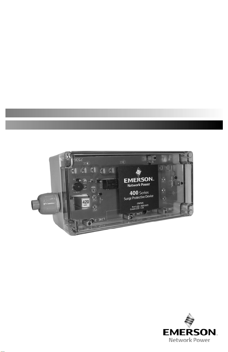
400 Series
430 & 440 Surge Protective Devices
Installation, Operation and Maintenance Manual
Installation, Operation and Maintenance Manual IO-70104 Rev 1, 1/2014
Page 2
EMERSON NETWORK POWER SURGE PROTECTIVE DEVICE
INSTALLATION, OPERATION AND MAINTENANCE MANUAL
TABLE OF CONTENTS
INSTALLATION
Environment .................................................................................................................... 2
Mounting ............................................................................................................................ 2
Wire Sizing/Routing ......................................................................................................... 2
Conduit Connection ........................................................................................................ 2
Wiring Connections .......................................................................................................................... 2
Applying Power ................................................................................................................................. 3
PRODUCT RATINGS AND LIMITATIONS
Voltage Protection Ratings .............................................................................................. 3
Circuit Ampacity Limitations ............................................................................................ 3
TROUBLESHOOTING/SERVICING/MAINTENANCE
Troubleshooting .............................................................................................................. 3
MODEL NUMBER CONFIGURATION
Model Number Configuration .......................................................................................... 3
Configuration & Voltage (Chart) ...................................................................................... 4
SPD WIRING and MOUNTING
Circuit Breaker and Wire Size .......................................................................................... 5
Parallel Wiring Diagram ................................................................................................... 5
Screw Mounting .............................................................................................................. 5
DIN Rail Mounting Kit ...................................................................................................... 5
Dimensional Information ................................................................................................. 5
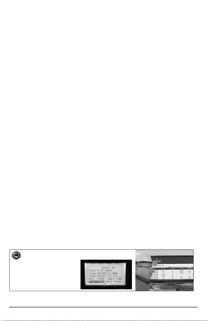
Units that include the ADVANCED TRANSIENT DETECTION SYSTEM monitoring option
See
MODEL NUMBER CONFIGURATION
on page 3 to verify the SPDs monitoring option.
Advanced Transient Detection System
Refer to manual IO-70109
for additional installation and
operation instructions.
Installation, Operation and Maintenance Manual IO-70106 Rev 3, 1/2015
1
Page 3

The Emerson Network Power 430 & 440 Surge Protective Devices are high quality, high energy
surge current diversion system designed to protect sensitive equipment from damaging
transient voltage surges resulting from load switching, lightning strikes and other sources.
The installer should perform the following steps to assure a quality installation. Please read all
instructions before starting the installation of this product. These instructions do not replace
national or local electrical codes — check applicable codes to ensure compliance.
INSTALLATION
DANGER! ONLY QUALIFIED PERSONNEL SHOULD INSTALL
OR SERVICE THIS SYSTEM. ELECTRICAL SAFETY PRE-
CAUTIONS MUST BE FOLLOWED WHEN INSTALLING OR
SERVICING THIS EQUIPMENT. TO PREVENT RISK OF ELECTRICAL SHOCK, TURN OFF AND
LOCK OUT ALL POWER SOURCES TO THE UNIT BEFORE MAKING ELECTRICAL
CONNECTIONS OR SERVICING.
DANGER! SEULEMENT LE PERSONNEL QUALIFIÉ DOIT INSTALLER OU MAINTENIR CE
SYSTÈME. DES PRÉCAUTIONS DE SÉCURITÉ EN ÉLECTRICITÉ DOIVENT ÊTRE SUIVIS LORS
DE L'INSTALLATION OU DE LA MAINTENANCE DE CET EQUIPEMENT. POUR EVITER TOUT
RISQUE DE CHOC ÉLECTRIQUE, DÉBRANCHEZ ET VEROUILLER TOUTES LES SOURCES D’
ALIMENTATION DE CET EQUIPEMENT AVANT DE LE BRANCHER OU LE MAINTENIR.
Environment — The unit is designed for operation indoors in ambient temperatures of 40ºC (-40ºF) to +85ºC (+185ºF) with a relative humidity of 0% to 95% (non-condensing). The
unit is provided in an industrial enclosure, which should not be installed in areas with excessive
dust, corrosive vapors, flammable materials or explosive atmospheres.
Mounting — Mount unit as close as possible to the service panel in close proximity to the
breaker that will feed the SPD. For best performance, unit should be positioned so that the
length of the wiring to the surge protective device (SPD) unit is minimized. Dimensional
information is shown on page 5-6.
NEMA 4X (Non-Metallic) enclosure - Remove cover on unit to gain access to the
mounting holes in case. Use #6 x 3/4” self-threading screws (provided), to mount the SPD
to wall or back plane. Replace cover on unit and torque cover screws to 10 IN-LBS, (see
drawing).
NEMA 12/4, (Metallic) enclosure – Mounting flanges accept 1/4 hardware.
Wire Sizing/Routing —To reduce the wiring impedance to surge currents, the phase, neutral
(if required), and ground conductors are recommended to be twisted together and routed in
the same raceway (conduit). Avoid any sharp bends in the conductors. All wiring must comply
with the National Electrical Code (NEC) and applicable local codes.
Conduit Connection — The SPD wires should feed through the plastic conduit piece supplied.
The conduit should be cut to match the distance from the unit to electrical panel. Use the
supplied conduit hub to connect to the electrical panel.
Wiring Connections — Before making connections to the unit, verify that the unit model
number and nameplate voltage rating are appropriate for connection to the intended power
source (See table).
1. It is recommended that a 20A circuit breaker be used for installation and connection to the
service panel.
2. Connect a white wire from the supply neutral to the neutral terminal/lug inside the SPD,
and connect a green wire from the source ground to the SPD ground terminal/lug.
3. Connect a black phase wire from each line on the service panel/circuit breaker to each
corresponding phase terminal/lug in the SPD.
4. If using remote sensing (Form C dry contact), connect wires to COM (orange), NC (blue),
and NO (yellow) respectively. Relay’s maximum switching capacity is 250VAC, 5A.
Installation, Operation and Maintenance Manual IO-70106 Rev 3, 1/2015
2
(continued)
Page 4

CAUTION – For proper and safe operation, neutral and
ground MUST be reliably connected. Failure to operate this
unit from a solidly grounded power source of the proper
2
configuration will reduce or impede operation, and may result in unit failure.
ATTENTION - Pour un fonctionnement correct et sûr, le neutre et la mise à la terre doit
être connectés de manière fiable. Défaut de faire fonctionner cet appareil à partir d'une
source d'alimentation solidement mise à la terre va réduire ou même empêcher le
fonctionnement correct et peut entraîner une défaillance de l'unité.
Applying Power — Apply power to the SPD and assure status indications are normal. Under
normal conditions, the green “OK” or “PHASE” LED(s) are illuminated and the red “REPLACE”
or “SERVICE” LED is OFF. If normal status indication does not exist, see “TROUBLESHOOTING”.
PRODUCT RATINGS AND LIMITATIONS
Voltage Protection Rating – To obtain the voltage protection ratings (VPRs), as obtained by
Underwriters Laboratories, Incorporated, in accordance with the Standard for Safety, Surge
Protective Devices (SPDs), Standard 1449 Third Edition, released 2009, marked on this product,
#12 AWG wire must be utilized to connect the 430/440 SPD to your facilities’ power grid.
Connections made with conductors other than #12 AWG may result in different VPRs.
Circuit Ampacity Limitations – This device has been investigated by Underwriters
Laboratories, Incorporated to withstand, without exposing live circuits or components on
power sources, a voltage of two times (2x) the device ratings, and fault currents of up to
200,000 AIC, as described in the Standard for Safety, Surge Protective Devices (SPDs), Standard
1449, Third Edition, released 2009.
TROUBLESHOOTING
If any of the diagnostic indicators indicates a problem (i.e. red LED ON, and/or green LED(s) OUT;
and/or alarm sounding), check all connections and voltages to the unit. If all connections are reliable,
and proper voltages are supplied to the unit, call Emerson Network Power Surge Protection, Inc at
607-721-8840.
N-G Overvoltage Indication – If all green “PHASE” LEDs are ON and red “SERVICE” LED is also ON this
indicates that the neutral to ground voltage at the connected panel may be 20 VAC or higher.
MODEL NUMBER CONFIGURATION
Model #: _ _ _ _ _ _ _ _ _ _ _ _ _
1 2 3 4 5 6 7 8 9 10 11 12 13
(1-3) Series
430 = Non-Modular, Basic
Monitoring
440 = Non-Modular;
Expanded Monitoring;
Scalable Surge Levels
(4-5) Configuration &
Voltage
See Chart on Next Page
(6-7) Surge Rating Per
Mode
05 = 50kA (430/440)
10 = 100kA (430/440)
15 = 150kA (440)
Installation, Operation and Maintenance Manual IO-70106 Rev 3, 1/2015
(8) Modes of Protection
A = All Modes of Protection
L = All modes plus Discrete L-L
(9) Connection Type
W = Wire Leads
N = Terminals/Compression
Lugs
(10) Monitoring Options
A = LED/Alarm/Relay (430/440)
L= “A” plus Surge LED (440)
C=”A” plus Surge Counter (440)
T= Advanced Transient
Detection System
See manual “IO-70109”
(11) Enclosure
J = NEMA Type 4X (plastic)
L = NEMA Type 12 (metal)
G = NEMA Type 4 (metal)
3
(12) UL 1449 Type
0 = No UL
1 = Type 1, 20kA
2 = Type 2, 20kA; UL 1283
(13) Accessories
S = Standard
X = SPD with additional
Options/Accessories
Page 5

(
)
CHART
CONFIGURATION & VOLTAGE
Installation, Operation and Maintenance Manual IO-70106 Rev 3, 1/2015
4
Page 6

SPD WIRING & MOUNTING
CIRCUIT BREAKER & WIRE SIZE
Overcurrent Protection: .......... 20A Recommended
Connection Wire
Summary Alarm Contacts ........ 250VAC, 5A Max
PARALLEL WIRING DIAGRAM
: ..................... Phase/Neutral/Ground; (12 AWG Recommended)
Designations are with AC Applied
Normally Open ............ (NO)
Normally Closed .......... (NC)
Common .................... (COM)
SCREW MOUNTING
Remove cover, and use #6 x 3/4”
self-threading screws (provided)
for mounting,
Replace cover, torque screws to
10 in/lbs.
DIMENSIONAL INFORMATION for Non-Metallic NEMA 4X Enclosure Option (“J”)
B
Model A B C D E Weight
430 7.1 [180] 5.1 [130] 2.6 [65] 6.4 [164] 4.5 [114] 2.8 lbs [1.3kg]
440 9.6 [244] 4.9 [124] 3.2 [81] 9 [229] 3.5 [90] 4.4 lbs [2.0kg]
A
D
E
1/2 NPT flexible
conduit (12”)
and connector
assembly
included.
C
4.0
[102]
2.0
[52]
Installation, Operation and Maintenance Manual IO-70106 Rev 3, 1/2015
5
Page 7

DIMENSIONAL INFORMATION for Metal Enclosure Options (NEMA 12=“L”, NEMA 4=”G”)
Models A B C D E Weight
430 8 [203] 6 [152] 3.8 [96] 8.75 [222] 4 [102] 7.0 lbs [3.2kg]
440 10 [254] 8 [203] 4.3 [109] 10.75 [273] 6 [152] 10.9 lbs [4.9kg]
D A
MOUNTING:
(x4) .31” [8mm] Diameter
¼” Hardware Recommended
C
B
E
430 SPD Only
440 SPD does not
have conduit entry
pre-drilled.
2.1
[53]
3.0
[76]
Recommended
Conduit Entry
Locations
440 SPD Only
430 SPDs have the conduit entry location pre-determined
with a ½” NPT conduit connector pre-installed for ease of
installation.
12” of ½” NPT flexible conduit and an additional conduit
connector is included with each 430 unit.
440 SPDs DO NOT have the conduit entry location predetermined. This allows for a more flexible installation. See
drawing for recommended conduit entry points.
Conduit Entry For NEMA Type 12/4 Units
Installation, Operation and Maintenance Manual IO-70106 Rev 3, 1/2015
6
Page 8

Emerson Network Power
Surge Protection
100 Emerson Parkway
Binghamton, NY 13905
800 288 6169 Phone (U.S. & Canada Only)
607 721 8840 (Outside U.S.)
607 722 8713 FAX
United States of America
Emerson Network Power
European Headquarters
Via Leonardo Da Vinci 8
Zona Industriale Tognana
35028 Piove Di Sacco (PD)
Italy
39 049 9719 111 Phone
39 049 5841 257 FAX
Emerson Network Power Asia Pacific
29/F, The Orient Square Building
F. Ortigas Jr. Road, Ortigas Center
Pasig City 1605
Philippines
+63 2 687 6615
+63 2 730 9572 FAX
Technical Support
800 288 6169 Toll-Free
607 721 8840 Phone
607 722 8713 FAX
EmersonNetworkPower.com/Surge
While every precaution has been taken to ensure accuracy and
completeness in this literature, Emerson Network Power assumes
no responsibility, and disclaims all liability for damages resulting
from use of this information or for any errors or omissions.
© 2014 Emerson Network Power. All rights reserved throughout
the world. Specifications subject to change without notice.
All names referred to are trademarks or registered trademarks
of their respective owners.
IO-70106 (Rev 3 1/15) Printed in USA
Installation, Operation and Maintenance Manual IO-70106 Rev 3, 1/2015
 Loading...